EP0803628A2 - Side visor having pinching sensing member and power window apparatus using the same - Google Patents
Side visor having pinching sensing member and power window apparatus using the same Download PDFInfo
- Publication number
- EP0803628A2 EP0803628A2 EP97106638A EP97106638A EP0803628A2 EP 0803628 A2 EP0803628 A2 EP 0803628A2 EP 97106638 A EP97106638 A EP 97106638A EP 97106638 A EP97106638 A EP 97106638A EP 0803628 A2 EP0803628 A2 EP 0803628A2
- Authority
- EP
- European Patent Office
- Prior art keywords
- window
- side visor
- window frame
- sensing
- external force
- Prior art date
- Legal status (The legal status is an assumption and is not a legal conclusion. Google has not performed a legal analysis and makes no representation as to the accuracy of the status listed.)
- Granted
Links
Images


Classifications
-
- B—PERFORMING OPERATIONS; TRANSPORTING
- B60—VEHICLES IN GENERAL
- B60J—WINDOWS, WINDSCREENS, NON-FIXED ROOFS, DOORS, OR SIMILAR DEVICES FOR VEHICLES; REMOVABLE EXTERNAL PROTECTIVE COVERINGS SPECIALLY ADAPTED FOR VEHICLES
- B60J10/00—Sealing arrangements
-
- E—FIXED CONSTRUCTIONS
- E05—LOCKS; KEYS; WINDOW OR DOOR FITTINGS; SAFES
- E05F—DEVICES FOR MOVING WINGS INTO OPEN OR CLOSED POSITION; CHECKS FOR WINGS; WING FITTINGS NOT OTHERWISE PROVIDED FOR, CONCERNED WITH THE FUNCTIONING OF THE WING
- E05F15/00—Power-operated mechanisms for wings
- E05F15/40—Safety devices, e.g. detection of obstructions or end positions
- E05F15/42—Detection using safety edges
- E05F15/44—Detection using safety edges responsive to changes in electrical conductivity
- E05F15/443—Detection using safety edges responsive to changes in electrical conductivity specially adapted for vehicle windows or roofs
-
- E—FIXED CONSTRUCTIONS
- E05—LOCKS; KEYS; WINDOW OR DOOR FITTINGS; SAFES
- E05Y—INDEXING SCHEME RELATING TO HINGES OR OTHER SUSPENSION DEVICES FOR DOORS, WINDOWS OR WINGS AND DEVICES FOR MOVING WINGS INTO OPEN OR CLOSED POSITION, CHECKS FOR WINGS AND WING FITTINGS NOT OTHERWISE PROVIDED FOR, CONCERNED WITH THE FUNCTIONING OF THE WING
- E05Y2900/00—Application of doors, windows, wings or fittings thereof
- E05Y2900/50—Application of doors, windows, wings or fittings thereof for vehicles
- E05Y2900/53—Application of doors, windows, wings or fittings thereof for vehicles characterised by the type of wing
- E05Y2900/55—Windows
-
- H—ELECTRICITY
- H01—ELECTRIC ELEMENTS
- H01H—ELECTRIC SWITCHES; RELAYS; SELECTORS; EMERGENCY PROTECTIVE DEVICES
- H01H2300/00—Orthogonal indexing scheme relating to electric switches, relays, selectors or emergency protective devices covered by H01H
- H01H2300/01—Application power window
-
- H—ELECTRICITY
- H01—ELECTRIC ELEMENTS
- H01H—ELECTRIC SWITCHES; RELAYS; SELECTORS; EMERGENCY PROTECTIVE DEVICES
- H01H3/00—Mechanisms for operating contacts
- H01H3/02—Operating parts, i.e. for operating driving mechanism by a mechanical force external to the switch
- H01H3/14—Operating parts, i.e. for operating driving mechanism by a mechanical force external to the switch adapted for operation by a part of the human body other than the hand, e.g. by foot
- H01H3/141—Cushion or mat switches
- H01H3/142—Cushion or mat switches of the elongated strip type
Definitions
- the point of action f will be positioned out of the sensible range of the sensing member 4. In this state the sensing member 4 can not sense the external force, causing the occurrence of the above-described trouble.
- a sensing member for sensing the external force is provided on a side visor body.
- this sensing member is disposed in the joining part of the side visor between a window frame and the side visor.
- an insulating holding member for holding a pair of conducting members to define a space may be made of a porous elastic material such as polyurethane polyethylene.
- an insulating holding member for holding a pair of conducting members to form a space may be produced of a porous elastic material.
- the porous elastic material be polyurethane or polyethylene.
- an elastic member 9 made of an elastic material for absorbing irregularities of these members 3 and 5 is attached by an adhesive to these members 3 and 5.
- a recess section 51 for mounting the cord switch 4 therein is formed in a part corresponding to the front portion 3b through to the upper portion 3c of the window frame 3.
- the insulating members 47 and 48 are formed of resin, and the non-adhering surfaces 47a and 48a of the insulating members 47 and 48 (in the insulating member 47, the surface facing the first and third conducting members 42 and 44; and in the insulating member 48, the surface facing the first and second conducting members 42 and 43) slidably contacts the conducting member which faces the surface.
- a reaction against the external force F acting on the side visor 5 is generated not only at the intersection between the line of action of the external force acting on the side visor 5 and the window frame 3 but in the vicinity of the intersection.
- the cord switch 4 is located in the joining part IV between the window frame 3 and the side visor 5. Therefore, if the external force F acts on a specific part of the side visor 5 for instance, there will never occur such a trouble that the external force F acts only on a specific part of the cord switch 4 corresponding thereto.
- the cord switch 4 is mounted in the joining part IV between the window frame 3 and the side visor 5, the driver or passenger will not touch the covered tube 41 when getting on or off the automobile. Therefore no consideration of the abrasion resistance of the covered tube 41 is needed.
- This design not only improves durability of the cord switch 4 but improves durability of a power window apparatus having the anti-pinching mechanism.
- the elastic member 9 interposed between the side visor 5 and the window frame 3 may be dispensed with.
- Reference numeral 404 designates a displaceable member made of resin which can be displaced with respect to the conducting members 401 and 402.
- This displaceable member 404 is provided with a through hole 405 through which the conducting members 401 and 402 are inserted.
- the holding member 403 and the displaceable member 404 are arranged alternately along the contour of the window frame 3.
- a triangular projection 404a protruding toward closing the window glass 2 is formed on the side of second conducting member 402 of the through hole 405, while a smooth flat surface is formed on the side of first conducting member 401.
- the holding member 403 is connected to the window frame 3 and the displacement member 404 is connected to the joining part IV of the side visor 5.
- the sectional form of the through hole 405 is oblong as shown in Fig. 9 so that the direction of long diameter will agree with the direction of operation (movement) of the window glass 2, and that the short diameter of the through hole 405 will nearly coincides with the diameter of the through hole 405.
- the oblong configuration of the through hole 405, two conducting members 401, and the window frame 3 constitute the displacement restricting member for restricting displacement of the displacement member 404 in a direction in which the displacement member 404 intersects the direction of movement of the window glass 2.
- both the conducting members 401 and 402 can be displaced or deformed even after the contact of the conducting member 402 with the first conducting member 401, and therefore it becomes possible to prevent the external force F from excessively increasing during the period of time lag so that it may change as indicated by a full line in Fig. 12.
- the holding member 403 is connected to the window frame 3 and the displacement member 404 is connected to the joining part IV of the side visor 5. It should be noted that the holding member 403 may be connected to the joining part IV of the side visor 5 and the displacement member 404, to the window frame 3.
- the cord switch 4 is mounted in the cover member 52 and the holding member 403 is connected to the inner wall of the cover member 52.
- the projection is not needed to be mounted in all the displacement member 404, and may be dispensed with in the region of the window frame 3 where the external force F caused by the pinching of a foreign object increases.
- a cord switch 4 is inserted in a bent section 52a of the cover member 52 as shown in Fig. 17.
- Reference numeral 52b denotes a stopper for restricting the maximum displacement of the side visor 5, and reference numeral 52c designates an adhesive tape for attaching the cover member 52 to the window frame 3.
- the cord switch 4 of the present embodiment is comprised of an insulating holding member 403 of porous elastic material such as polyurethane or polyethylene which has a U-section intersecting at right angles the longitudinal direction, a first conducting member 401 thermally secured on the inner wall bottom of the insulating holding member 403, and a second conducting member 402 thermally secured to the opening of the insulating holding member 403.
- an insulating holding member 403 of porous elastic material such as polyurethane or polyethylene which has a U-section intersecting at right angles the longitudinal direction
- a first conducting member 401 thermally secured on the inner wall bottom of the insulating holding member 403, and a second conducting member 402 thermally secured to the opening of the insulating holding member 403.
- the insulating holding member 403 and the cover member 52 may be integrally formed.
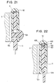
- the stopper 52b may be formed on the side of the open end section of the cover member 52 as shown in Fig. 22.
- an elastic member such as a plate spring may be used for bridging between the side visor 5 and the window frame 3, thereby enabling to prevent chattering of the side visor 5 caused by disturbance such as vehicle vibration.
- an elastic member such as a plate spring
- the first conducting member 42 is formed flat, and therefore the first conducting member 42 will not move in between the second and third conducting members 43 and 44. Consequently the external force F can be sensed exactly.
- the present embodiment has a purpose of reducing a malfunction of not only the cord switch 4 but the entire mechanism of the power window apparatus having the anti-pinching mechanism.
- the load detecting circuit comparing a detected value of a speed sensor 1a provided on the driving motor 1 as shown in Fig. 29, determines that the driving load exceeds a specific value and outputs an overload signal 1b to an AND gate 61 in the event the detected window moving speed output of the speed sensor 1a decreases below the specific value. Furthermore, both a first signal 4a generated when the first cord switch 4 senses an external force exceeding the specific value and a second signal 40a generated when the second cord switch 40 senses an external force exceeding a specific value are inputted to an OR gate 62. Together with a pinching detection signal 62a from the OR gate 62, a window closing signal 63a is inputted to an AND gate 61 from a motor driving circuit 63 for driving the driving motor 1. The window closing signal 63a is produced when the driving motor 1 is turning in a direction in which the window glass 2 is closed.
- the second cord switch 40 and the OR gate 62 are provided. However, it should be noticed that both of them may be eliminated, and the first signal 4a may be inputted from the first cord switch 4 directly to the AND gate 61. Also the second cord switch 40 may be disposed on the outside of the weatherstrip 8 to sense the external force acting on the window frame 3.
- the cord switch 4 is attached to the edge portion 5a of the side visor 5.
- the cord switch 4 has at least three conducting members (four in the present embodiment) 401, 402, 407 and 408 which are disposed in the elastically deformable insulating member 403 such as rubber to face one another with insulating space 405 thereamong.
- a cord switch (4) operable in response to a specific external force (F) is mounted in a joining part of a side visor (5) between a window frame (4) and the side visor (5).
- the cord switch (4) senses the external force acting on the side visor (5), reliably detecting a foreign object (7) pinched between a window glass (2) and the side visor (5).
Landscapes
- Engineering & Computer Science (AREA)
- Mechanical Engineering (AREA)
- Window Of Vehicle (AREA)
- Power-Operated Mechanisms For Wings (AREA)
- Push-Button Switches (AREA)
- Insulated Conductors (AREA)
- Geophysics And Detection Of Objects (AREA)
Abstract
Description
- The present invention relates to a side visor and a power window apparatus for vehicles using the same for an anti-pinching mechanism.
- A power window apparatus having an anti-pinching mechanism, disclosed in Japanese Utility Model Laid-Open No. Sho 64-53389 for instance, is provided with a sensing member, such as a pressure-sensitive tube sensor for sensing an external force, along the inside periphery of a window frame. This sensing member senses an external force applied when a foreign object is caught between a window glass and the window frame, to thereby stop a driving motor for moving the window glass up and down.
- A conventional sensing member as disclosed in Japanese Patent Laid-Open No. Hei 6-260054 for instance, has a predetermined space with band-like electrodes of conducting rubber formed face to face and with elastic members of insulating rubber arranged on both ends in the direction of width intersecting at right angles the longitudinal direction of the band-like electrodes. A specific voltage is applied between the band-like electrodes to sense the external force with the voltage thus applied between the band-like electrodes.
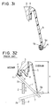
- In a vehicle mounted with a side visor for shading the peripheral edge of the window opening, the upward or downward movement of the window glass will not stop if a foreign object is caught between the window glass and the side visor as shown in Fig. 32. A foreign object 7 comes in contact with the
top end portion 2a of awindow glass 2, theedge portion 5a of aside visor 5, and aweatherstrip 8 closing a clearance between thewindow glass 2 and the window frame (vehicle body) 3. An external force F acting on the sensingmember 4 acts on the point of action f at a contact point between theweatherstrip 8 and the foreign object 7; therefore the larger the size h of the outside dimensions of theside visor 5 in a direction in which thewindow glass 2 is opened and closed, the more the point of action f moves toward the vehicle interior. - Accordingly if the size h exceeds a specific value, the point of action f will be positioned out of the sensible range of the
sensing member 4. In this state thesensing member 4 can not sense the external force, causing the occurrence of the above-described trouble. - Furthermore, because the
edge portion 5a of theside visor 5 is positioned on the closed side of thewindow glass 2 off the location of thesensing member 4, the foreign object 7 will be caught between thewindow glass 2 and theside visor 5 before it contacts thesensing member 4 particularly when the foreign object 7 comes in from above toward the vehicle interior as shown by two-dot chain line in Fig. 32, thus resulting in the aforesaid trouble. - In a vehicle not provided with the
side visor 5, on the other hand, the foreign object 7 is caught only between thewindow glass 2 and thewindow frame 3; therefore there will occur no trouble resulting from the aforesaid cause. - In view of the above-described disadvantages, it is a primary object of the present invention to provide a side visor having a pinching detection function.
- It is a secondary object of the present invention to provide a power window apparatus designed to reliably operate an anti-pinching mechanism even in a window fitted with a side visor.
- For attaining the primary object, according to the present invention, a sensing member for sensing the external force is provided on a side visor body. Preferably, this sensing member is disposed in the joining part of the side visor between a window frame and the side visor. As the sensing member, an insulating holding member for holding a pair of conducting members to define a space may be made of a porous elastic material such as polyurethane polyethylene.
- For attaining the secondary object, according to an aspect of the present invention, a closing operation stopping member is provided. This stopping member will stop movement of a window body toward closing when an external force acting on a side visor which is sensed by the sensing member exceeds a predetermined value. The sensing member thus senses the external force acting on the side visor to thereby detect a foreign object being pinched. It is, therefore, possible to prevent such a trouble that the upward movement of the window body will not be stopped in case the foreign object is pinched between the window body and the side visor.
- Preferably, the sensing member is disposed in the joining part between the side visor and the window frame. Therefore, even if the part of intersection between the sensing member and the line of action of the external force acting on the side visor is a dead zone where the external force can not be sensed, the external force can be sensed by a reaction from the vicinity of the part of intersection between the window frame and the line of action of the external force.
- The sensing member may be disposed within a cover member covering the joining part from above.
- The sensing member may be comprised of a holding member for holding a pair of conducting members, and a displacement member which makes a relative displacement with respect to the pair of conducting members. Furthermore, the displacement member may be provided with a displacement restricting member for restricting the displacement of the displacement member in a direction which intersects the direction of movement of the window body.
- Alternatively, as the sensing member, an insulating holding member for holding a pair of conducting members to form a space may be produced of a porous elastic material. At this time, it is preferable that the porous elastic material be polyurethane or polyethylene.
- According to another aspect of the present invention, movement of a window body toward closing may be stopped when an external force sensed by a sensing member exceeds a predetermined value and when a detected value of a driving load of the window body driving device detected by a load detecting member exceeds a predetermined value.
- According to a further aspect of the present invention, movement of a window body toward closing may be stopped when an external force sensed by at least one of a first sensing member for sensing an external force acting on a side visor and a second sensing member for sensing an external force acting on a window frame exceeds a predetermined value and also when a detected value of the driving load of a window body driving device detected by a load detecting member exceeds a predetermined value. Preferably, the second sensing member may be inserted in a weatherstrip.
- Other objects, features and advantages of the present invention will become more apparent from the following detailed description when read with reference to the accompanying drawings, in which:
- Fig. 1 is a side view of an automotive vehicle to which the present invention is applied;
- Fig. 2 is a schematic view showing a power window apparatus according to a first embodiment of the present invention;
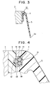
- Fig. 3 is a sectional view of a cord switch used in the first embodiment and taken along line III-III in Fig. 2;
- Fig. 4 is an enlarged view of a part IV in Fig. 3;
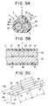
- Figs. 5A to 5C are explanatory views showing the structure of the cord switch in the first embodiment;
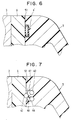
- Fig. 6 is a sectional view showing a modification of the cord switch in the first embodiment;
- Fig. 7 is a sectional view of a cord switch used in a second embodiment of the present invention;
- Fig. 8 is a sectional view of a cord switch used in a third embodiment of the present invention;
- Fig. 9 is a sectional view taken along line IX-IX in Fig. 8;
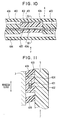
- Fig. 10 is a sectional view of the cord switch used in the third embodiment;
- Fig. 11 is a sectional view taken along line XI-XI in Fig. 10;
- Fig. 12 is a graph showing a relationship between an external force and time;
- Fig. 13 is a sectional view of a cord switch used in a fourth embodiment of the present invention;
- Fig. 14 is a sectional view taken along line XIV-XIV in Fig. 13;
- Fig. 15 is a sectional view showing a side visor attached with a cover member;
- Fig. 16A is a front view showing the side visor provided with the cord switch, and Fig. 16B is an enlarged sectional view of the cord switch mounted in the side visor;
- Fig. 17 is a sectional view of a side visor used in a sixth embodiment of the present invention;
- Fig. 18 is a sectional view of a cord switch used in the sixth embodiment;
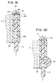
- Fig. 19 is a sectional view of the side visor used in the sixth embodiment;
- Fig. 20 is a sectional view showing a modification of the side visor used in the sixth embodiment;
- Fig. 21 is a sectional view showing another modification of the side visor used in the sixth embodiment;
- Fig. 22 is a sectional view showing a further modification of the side visor used in the sixth embodiment;
- Figs. 23A and 23B are sectional views sowing a still further modification of the side visor used in the sixth embodiment;
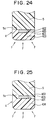
- Fig. 24 is a sectional view showing the edge portion of a side visor used in a seventh embodiment of the present invention;
- Fig. 25 is a sectional view showing the edge portion of a side visor used in an eighth embodiment of the present invention;
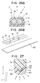
- Figs. 26A and 26B are explanatory views of a cord switch used in a ninth embodiment of the present invention;
- Fig. 27 is a sectional view showing the edge portion of a side visor used in a tenth embodiment of the present invention;
- Fig. 28 is a sectional view showing an eleventh embodiment of the present invention;
- Fig. 29 is an electric wiring diagram of a power window apparatus according to the eleventh embodiment; and
- Figs. 30A and 30B are a sectional view and an enlarged view showing a cord switch and a side visor used in a twelfth embodiment of the present invention;
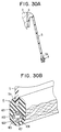
- Fig. 31 is a sectional view showing a modification of the cord switch and the side visor used in the twelfth embodiment; and
- Fig. 32 is a sectional view showing a conventional power window apparatus.
- Hereinafter preferred embodiments of the present invention will be described in more detail with reference to the accompanying drawings.
- In Figs. 1, 2 and 3,
reference numeral 1 denotes a driving motor (a window body driving member) for driving to move up and down a window glass (a window body) 2 which opens and closes awindow opening 3a, andreference numeral 3 denotes a window frame forming thewindow opening 3a. Along the exterior periphery of thewindow frame 3 a side visor (side visor body) 5 made of resin for shading the upper periphery of thewindow opening 3a is mounted. At a joining part IV (Fig. 3) of theside visor 5 between theside visor 5 and thewindow frame 3, one cord switch (sensing member) 4 for sensing the external force acting on theside visor 5 is arranged through from the front portion 3b to theupper portion 3c of thewindow frame 3. - As shown in Fig. 4, between the
window frame 3 and theside visor 5, anelastic member 9 made of an elastic material for absorbing irregularities of thesemembers members side visor 5 which is in contact with theelastic member 9, arecess section 51 for mounting thecord switch 4 therein is formed in a part corresponding to the front portion 3b through to theupper portion 3c of thewindow frame 3. - The
cord switch 4 is shown in Figs. 5A through 5C, in which in Fig. 5B shows the section along line C-O1-C in Fig. 5A.Numeral 41 designates an elastically deformable covered tube made of an insulating material such as a resin. In this coveredtube 41 are arranged three first to third elasticallydeformable conducting members 42 to 44 extending in the longitudinal direction. These conductingmembers 42 to 44 have nearly an equal circular sectional form. In the present embodiment, the wire diameter of the conductingmembers 42 to 44 is about 0.5 to 1.0 mm. These conductingmembers 42 to 44 are arranged in a triangular form (O1-O2-O3) in such a manner that one conducting member will face the other two conducting members. The conductingmembers 42 to 44 are formed of a high fatigue-limit metal such as stainless steel, phosphor bronze, etc. - On the second and
third conducting members members spaces 45 and 46 between the conductingmembers 42 to 44 are securely attached, covering a part of the circumferential side face of the conductingmembers members tube 1, and are arranged such that one insulating member will be positioned between adjacent ones of the other insulating members. - The insulating
members non-adhering surfaces members 47 and 48 (in the insulatingmember 47, the surface facing the first andthird conducting members member 48, the surface facing the first and second conductingmembers 42 and 43) slidably contacts the conducting member which faces the surface. -
Electrical wirings 42a to 44a are connected to the ends in the longitudinal direction of the conductingmembers 42 to 44, respectively. Thesewirings 42a to 44a, as shown in Fig. 1, are connected to acontrol device 6 and a specific voltage is applied between the first conductingmember 42 and the second conductingmember 43 and between the first conductingmember 42 and the third conductingmember 44. Thus, as shown for instance in Fig. 5 B, when the first conductingmember 42 deflects with the external force F being acting thereon, the first conductingmember 42 contacts the second conductingmember 43 or the third conductingmember 44, or both of the second andthird conducting members member 42 and the second conductingmember 43, or between the first conductingmember 42 and the third conductingmember 44. Thus thecontrol device 6 detects that a foreign object is pinched between thewindow frame 3 and thewindow glass 2, giving asignal 6a to the drivingmotor 1 to stop the opening and closing operation of thewindow glass 2. - In an automotive vehicle door having the side visor, a foreign object, if pinched, will contact the
side visor 5 and thewindow glass 2. That is, in the event the foreign object is pinched in the automotive door having theside visor 5, the foreign object contacts at least both of thelowermost edge portion 5a of theside visor 5 and thetop end portion 2a of the window glass 2 (Fig. 32). - Therefore, according to the present embodiment, the
cord switch 4 detects the pinching of the foreign object by sensing the external force F acting on theside visor 5, and therefore it is possible to prevent the trouble that if the foreign object is pinched between thewindow glass 2 and theside visor 5, the upward and downward movement of thewindow glass 2 will not stop. - A reaction against the external force F acting on the
side visor 5 is generated not only at the intersection between the line of action of the external force acting on theside visor 5 and thewindow frame 3 but in the vicinity of the intersection. Thecord switch 4 is located in the joining part IV between thewindow frame 3 and theside visor 5. Therefore, if the external force F acts on a specific part of theside visor 5 for instance, there will never occur such a trouble that the external force F acts only on a specific part of thecord switch 4 corresponding thereto. - Accordingly, if the conducting
members 42 to 44 are located in the dead zones which will not be deflected (the current will not flow) when the specific part of thecord switch 4 receives the external force F like the immediately upper part of the insulatingmembers members 42 to 44 in the vicinity of the insulatingmembers window frame 3, becoming ready for energizing. Therefore, it is possible to reliably sense the external force irrespective of the part of action of the external force on theside visor 5. - The foreign object, if pinched, contacts the
edge portion 5a of theside visor 5 as described above. It is, therefore, possible to dispose thecord switch 4 on theedge portion 5a of theside visor 5. However, theedge portion 5a of theside visor 5 is located in a position where theedge portion 5a easily contacts a driver or a passenger, regardless of the pinching of a foreign object, when he gets on or off the automobile. Therefore in arranging thecord switch 4 on theedge portion 5a of theside visor 5, it is necessary to take due consideration of the abrasion resistance of the coveredtube 41. - According to the present embodiment, because the
cord switch 4 is mounted in the joining part IV between thewindow frame 3 and theside visor 5, the driver or passenger will not touch the coveredtube 41 when getting on or off the automobile. Therefore no consideration of the abrasion resistance of the coveredtube 41 is needed. This design not only improves durability of thecord switch 4 but improves durability of a power window apparatus having the anti-pinching mechanism. - It is to be noticed that the
cord switch 4 used in the present embodiment is not limited to the above-described one and may be another type of cord switch 4' shown in Fig. 6. - The
elastic member 9 interposed between theside visor 5 and thewindow frame 3 may be dispensed with. - In the present embodiment, as shown in Fig. 7, the
side visor 5 is a molding of an insulating resin. The insulatingmembers cord switch 4 is molded integrally with theside visor 5 so that the coveredtube 41 in the first embodiment is not used. Thus it becomes possible to reduce the number of components, therefore enabling to decrease the manufacturing cost of the power window apparatus having the anti-pinching mechanism. - In Figs. 8 and 9,
reference numerals window frame 3 and disposed face to face across a predetermined space. These conductingmembers member 403 of resin joined to thewindow frame 3. - In the present embodiment the conducting
members members member 403, have a circular cross section, and are made of stainless steel or phosphor bronze. -
Reference numeral 404 designates a displaceable member made of resin which can be displaced with respect to the conductingmembers displaceable member 404 is provided with a throughhole 405 through which the conductingmembers member 403 and thedisplaceable member 404 are arranged alternately along the contour of thewindow frame 3. - A
triangular projection 404a protruding toward closing thewindow glass 2 is formed on the side of second conductingmember 402 of the throughhole 405, while a smooth flat surface is formed on the side of first conductingmember 401. - The holding
member 403 is connected to thewindow frame 3 and thedisplacement member 404 is connected to the joining part IV of theside visor 5. Theside visor 5, therefore, is secured on thewindow frame 3 through thedisplacement member 404, conductingmembers member 403. - The sectional form of the through
hole 405 is oblong as shown in Fig. 9 so that the direction of long diameter will agree with the direction of operation (movement) of thewindow glass 2, and that the short diameter of the throughhole 405 will nearly coincides with the diameter of the throughhole 405. The oblong configuration of the throughhole 405, two conductingmembers 401, and thewindow frame 3 constitute the displacement restricting member for restricting displacement of thedisplacement member 404 in a direction in which thedisplacement member 404 intersects the direction of movement of thewindow glass 2. -
Reference numeral 406 denotes a sealing member made of an elastic material, such as rubber, for preventing entrance of foreign substances, for example rain water, into thecord switch 4. - If the external force F acts on the
side visor 5, theside visor 5 moves toward closing (upwardly) as shown in Figs. 10 and 11, thus moving thedisplacement member 404 upwardly. At this time, the external force F concentratedly acts on the conductingmember 402 through theprojection 404a, to deflect the second conductingmember 402 into contact with the first conductingmember 401, thereby detecting the external force F. - According to the cord switch 400 of the present embodiment, the displacement of the
displacement member 404 in the direction intersecting the direction of window glass operation is restricted by the oblong hole configuration of the throughhole 405. Therefore there will not occur such an error as detecting an external force of wind for example exerted in a direction intersecting the direction of operation of thewindow glass 2. Only the external force F resulting from the pinching of a foreign object can be detected. - Since both the conducting
members members member 403, a difference in the curvature radius of both the conductingmembers cord switch 4 is located in thebent section 3d (Fig. 2) of thewindow frame 3. Therefore, it is possible to prevent the trouble that both the conductingmembers bent section 3d. - The
control device 6 generates asignal 6a at time t1 when the external force F (F1 in Fig. 12) is detected with the contact of both the conductingmembers window glass 2 will stop or reverse at time t2 with a time lag caused by the moment of inertia of the drivingmotor 1 and the inertia force of thewindow glass 2 after the detection of the external force F (this phenomenon is called the time lag). - Therefore, when the external force F is detected and then the
signal 6a is generated, the pinching of a foreign object will proceed until thewindow glass 2 stops or reverses. - Here, in the cord switch 4' shown in Fig. 6 for example, the rigidity of the cord switch 4' increases after both the conducting members contact, resulting in a sudden increase in the external force F produced as indicated by a dot-and-chain line in Fig. 12.
- On the contrary, according to the
cord switch 4 of the present embodiment, both the conductingmembers member 402 with the first conductingmember 401, and therefore it becomes possible to prevent the external force F from excessively increasing during the period of time lag so that it may change as indicated by a full line in Fig. 12. - In the present embodiment, the holding
member 403 is connected to thewindow frame 3 and thedisplacement member 404 is connected to the joining part IV of theside visor 5. It should be noted that the holdingmember 403 may be connected to the joining part IV of theside visor 5 and thedisplacement member 404, to thewindow frame 3. - Although in the foregoing third embodiment the
cord switch 4 including both the conductingmembers member 403, and thedisplacement member 404 is disposed in such a manner that its entire part is covered with the sealingmember 406, as shown in Figs. 13 and 14 the sealingmember 406 is provided only in the part of contact between the holdingmember 403 and thedisplacement member 404. Figs. 13 and 14 indicate thecord switch 4 on which the external force F is acting. - In the present embodiment, on the upper side of the
side visor 5, acover section 5b is formed integrally with theside visor 5 to prevent the entry of rain water directly into thecord switch 4. - Although in the fourth embodiment the
cover section 5b is formed integral with theside visor 5, in the present embodiment shown in Fig. 15 and Figs. 16A and 16B, theside visor 5 is slidably held in the up-and-down direction (in the direction in which thewindow glass 2 is opened and closed), and at the same time acover member 52 is provided separately from theside visor 5, having a U-bent section and covering as if holding the joining part of theside visor 5 from above. The inner wall of thecover member 52 serves also as a displacement restricting member (a guide wall) which allows theside visor 5 to slide only in the up-and-down direction. - In the present embodiment, the
cord switch 4 is mounted in thecover member 52 and the holdingmember 403 is connected to the inner wall of thecover member 52. The projection is not needed to be mounted in all thedisplacement member 404, and may be dispensed with in the region of thewindow frame 3 where the external force F caused by the pinching of a foreign object increases. - When the projection is not provided, the external force F is uniformly distributed to the second conducting
member 402. Therefore the external force F necessary for contacting the conductingmembers displacement member 404 provided with the projection. - Furthermore, the sizes L1 and L2 of the
displacement member 404 may be changed in the region parallel with the longitudinal direction of both the conductingmembers window frame 3. In the present embodiment, the size L1 in theupper portion 3c is smaller than the size L2 in the front portion 3b. - In the present embodiment, a
cord switch 4 is inserted in abent section 52a of thecover member 52 as shown in Fig. 17.Reference numeral 52b denotes a stopper for restricting the maximum displacement of theside visor 5, and reference numeral 52c designates an adhesive tape for attaching thecover member 52 to thewindow frame 3. - The
cord switch 4 of the present embodiment, as shown in Fig. 18, is comprised of an insulating holdingmember 403 of porous elastic material such as polyurethane or polyethylene which has a U-section intersecting at right angles the longitudinal direction, a first conductingmember 401 thermally secured on the inner wall bottom of the insulating holdingmember 403, and asecond conducting member 402 thermally secured to the opening of the insulating holdingmember 403. - Thermal securing mentioned above is a welding process including disposing heated conducting
members member 403, for thermally attaching the conductingmembers member 403. Thespace 405 provided between both the conductingmembers member 403 by the heat used in thermally securing the first conductingmember 401. - As shown in Fig. 19, the
side visor 5 on which the external force F is acting upwardly with a foreign object pinched causes the conductingmembers side visor 5, theside visor 5 displaces toward thebent section 52a, thus deforming the insulating holdingmember 403 into contact with the conductingmembers - In the present embodiment, as shown in Figs. 20 and 21 showing respectively the
side visor 5 on which no external force F is acting and on which the external force F is acting, the insulating holdingmember 403 and thecover member 52 may be integrally formed. Thestopper 52b may be formed on the side of the open end section of thecover member 52 as shown in Fig. 22. - Also as shown in Figs. 23A and 23B, an
elastic member 52d such as rubber, spring, etc., which produces an elastic force for pressing normally thecord switch 4 so that the conductingmembers side visor 5. Therefore, as shown in Fig. 23A, when no external force is acting on theside visor 5, both the conductingmembers side visor 5, thecord switch 4 may be operated so that both the conductingmembers - In Figs. 19 to 23, an elastic member such as a plate spring may be used for bridging between the
side visor 5 and thewindow frame 3, thereby enabling to prevent chattering of theside visor 5 caused by disturbance such as vehicle vibration. Thus it becomes possible to prevent the cord switch malfunction (improper signal generation for pinching of a foreign object despite no actual pinching of any foreign object). - The present embodiment, as shown in Fig. 24, has the
cord switch 4 disposed in thelowermost edge portion 5a of theside visor 5. It should be noted that the cord switch is not limited to thecord switch 4 described in the fifth and sixth embodiments and may be any type of cord switch described in the first to fourth embodiments. - In the
cord switch 4 shown in Fig. 25, aspace 405 and both conductingmembers edge portion 5a of theside visor 5 and a cover section 434 is provided for covering theedge side 5a which will come into contact with a foreign object. The cover section 434 is made of a porous elastic material such as polyurethane, polyethylene, etc. - The
cord switch 4, as shown in Figs. 26A and 26B, uses a flat conducting member as the first conductingmember 42. Thecord switch 4 of the present embodiment is disposed in theedge portion 5a of thewindow frame 3 or theside visor 5. It is desirable that the second andthird conducting members window glass 2 is opened). - When the conducting
members 42 to 44 are arranged in a triangular form as in the first embodiment, the first conductingmember 42 will not deflect within the coveredtube 41 but will move in between the second andthird conducting members tube 41 has a low rigidity when the external force F acts from a direction perpendicular to the linear direction connecting for example thecenters 02, 03 of the second andthird conducting members member 42. Therefore, if the external force F acts, the first conductingmember 42 and the second andthird conducting members - According to the present embodiment, the first conducting
member 42 is formed flat, and therefore the first conductingmember 42 will not move in between the second andthird conducting members - As shown in Fig. 27, the
cord switch 4 of the present embodiment is disposed in theedge portion 5a of theside visor 5. Both conductingmembers window glass 2 is opened, for the purpose of providing a wide sensing range. Both the conductingmembers member 403 made of a porous elastic member such as polyurethane, polyethylene, etc. The insulating holdingmember 403 serves also as a protective cover covering both the conductingmembers - The present embodiment has a purpose of reducing a malfunction of not only the
cord switch 4 but the entire mechanism of the power window apparatus having the anti-pinching mechanism. - That is, in addition to the cord switch (first cord switch) 4 for sensing the external force acting on the
side visor 5 described in the above-described embodiments, another cord switch (second cord switch) 40 is disposed in theweatherstrip 8 as shown in Fig. 28 and also a load detecting circuit is provided for detecting the driving load of the drivingmotor 1. - The load detecting circuit, comparing a detected value of a speed sensor 1a provided on the driving
motor 1 as shown in Fig. 29, determines that the driving load exceeds a specific value and outputs anoverload signal 1b to an ANDgate 61 in the event the detected window moving speed output of the speed sensor 1a decreases below the specific value. Furthermore, both a first signal 4a generated when thefirst cord switch 4 senses an external force exceeding the specific value and asecond signal 40a generated when thesecond cord switch 40 senses an external force exceeding a specific value are inputted to anOR gate 62. Together with a pinching detection signal 62a from theOR gate 62, awindow closing signal 63a is inputted to an ANDgate 61 from amotor driving circuit 63 for driving the drivingmotor 1. Thewindow closing signal 63a is produced when the drivingmotor 1 is turning in a direction in which thewindow glass 2 is closed. - A
control signal 64a from acontrol switch 64 which is operated by a passenger to open and close thewindow glass 2, and astop signal 61a outputted from the ANDgate 61, are inputted into acontrol circuit 65. Usually thecontrol circuit 65 operates themotor driving circuit 63 in accordance with thecontrol signal 64a. When thestop signal 61a is outputted from the ANDgate 61, thecontrol circuit 65 reverses or stop the drivingmotor 1. - That is, the power window apparatus of the present embodiment functions to reverse or stop the window glass by detecting the pinching of a foreign object in the event that an external force sensed by at least one of the
first cord switch 4 and thesecond cord switch 40 exceeds a specific value and that the driving load of the drivingmotor 1 exceeds a specific value during window glass moving operation. - In the present embodiment, the
second cord switch 40 and theOR gate 62 are provided. However, it should be noticed that both of them may be eliminated, and the first signal 4a may be inputted from thefirst cord switch 4 directly to the ANDgate 61. Also thesecond cord switch 40 may be disposed on the outside of theweatherstrip 8 to sense the external force acting on thewindow frame 3. - Furthermore, in the present embodiment, the driving load is detected by detecting the rotational speed of the driving
motor 1, but may be detected by detecting the value f the electric current flowing into the drivingmotor 1. - In the present embodiment, as shown in Figs. 30A and 30B, the
cord switch 4 is attached to theedge portion 5a of theside visor 5. Thecord switch 4 has at least three conducting members (four in the present embodiment) 401, 402, 407 and 408 which are disposed in the elastically deformable insulatingmember 403 such as rubber to face one another with insulatingspace 405 thereamong. - Each of the conducting members is partly embedded in the inner wall of the insulating
member 403 under the condition that those are disposed spirally in the insulatingmember 403. Voltages are applied to the conductingmembers member 401, for instance) is kept at a potential different from that of the remaining conducting members (members side visor 5 can be detected when the insulatingmember 403 deforms and the conducting members of different potentials contact. - In the
cord switch 4 according to the present embodiment, other voltages may also be applied so that the conductingmembers - Further, as shown in Fig. 31, the
edge portion 5a of theside visor 5 may be bent toward the vehicle interior and thecord switch 4 may be disposed at thebent portion 5b. - The foregoing embodiments may be modified further in many other ways without departing from the spirit and scope of the invention.
- To provide a power window apparatus which can reliably actuate an anti-pinching mechanism even in a window provided with a side visor, a cord switch (4) operable in response to a specific external force (F) is mounted in a joining part of a side visor (5) between a window frame (4) and the side visor (5). The cord switch (4) senses the external force acting on the side visor (5), reliably detecting a foreign object (7) pinched between a window glass (2) and the side visor (5).
Claims (16)
- A power window apparatus, comprising:a window body (2) for opening and closing a window opening (3a) formed by a window frame (3);a side visor (5) provided along an exterior periphery of said window frame (3), for providing shade to the periphery of said window opening (3a);a sensing member (4) for sensing an external force acting on said side visor (5); andwindow closing operation stopping member (1, 6, 61-65) for stopping a closing motion of said window body (2) when the external force sensed by said sensing member (4) exceeds a preset value.
- A power window apparatus as claimed in claim 1, wherein:
said sensing member (4) is located in a joining part (IV) where said side visor (5) is attached to said window frame (3). - A power window apparatus as claimed in claim 2, further comprising:a cover member (52) joined to said window frame (3) for holding said side visor (5) slidably in an up-and-down direction and covering said joining part from above;said sensing member (4) being located within said cover member (52).
- A power window apparatus as claimed in claim 2 or 3, wherein said sensing member (4) includes:a pair of conducting members (401, 402) extended along said window frame (3) and disposed face to face at a predetermined spacing therebetween;a holding member (403) for holding said pair of conducting members (401, 402); anda displacement member (404) positioned displaceably with respect to said holding member (403) and to said pair of conducting members (401, 402),
wherein said holding member (403) is connected to one of said window frame (3) and said side visor (5), and said displacement member (404) is connected to the other of said window frame (3) and said side visor (5). - A power window apparatus switching device as claimed in claim 4, wherein:
said pair of conducting members (401, 402) are disposed face to face in a direction in which said window body (2) is opened and closed; and
said displacement member (404) being provided with displacement restricting member (3, 405) for restricting the displacement of said displacement member (404) in a direction intersecting the direction in which said window body (2) is opened and closed. - A power window apparatus as claimed in one of claims 1 to 3, wherein:
said sensing member (4) has a pair of conducting members (401, 402) extended along said window frame (3) and disposed face to face across a predetermined space (405); and
an insulating holding member (403) made of a porous elastic material for holding said pair of conducting members (401, 402) to thereby define said space (405). - A power window apparatus as claimed in claim 6, wherein:
said insulating holding member (403) is made of at least one of polyurethane and polyethylene. - A power window apparatus, comprising:a window body (2) for opening and closing a window opening (3a) formed in a window frame (3);a side visor (5) provided along an exterior periphery of said window frame (3), for providing shade to a periphery of said window opening (3a);a sensing member (4) for sensing an external force acting on said side visor (5);a window body driving member (1) for driving said window body (2);a load detecting member (1a) for detecting a driving load of said window body driving member (1); andwindow closing operation stopping member (61 - 65) for stopping the movement of said window body (2) toward closing when the external force sensed by said sensing member (4) exceeded a preset value and also when a detection value detected by said load detecting member (1a) exceeds a preset value.
- A power window apparatus, comprising:a window body (2) for opening and closing said window opening (3a) formed in said window frame (3);a side visor (5) provided along an exterior periphery of said window frame (3) for providing shade to a periphery of said window opening (3a);a first sensing member (4) for sensing an external force acting on said side visor (5);a second sensing member (4) disposed on said window frame (3) for sensing an external force acting on said window frame (3);a window body driving member (1) for driving said window body (2);a load detecting member (1a) for detecting a driving load of said window body driving member (1); andwindow closing operation stopping means (61 - 65) for stopping the movement of said window body (2) toward closing when at least one of said first sensing member (4) and said second sensing member (40) exceeds a preset value and a detection value detected by said load detecting member (1a) exceeded a preset value.
- A power window apparatus as claimed in claim 9, wherein:
said second sensing member (40) is disposed in a weatherstrip (8) installed along the periphery of said window frame (3). - A side visor for a window frame, comprising:a side visor body portion (5) molded in a shape to shade a periphery of a window opening (3a) formed in said window frame (3); anda sensing member (4) for sensing an external force acting on said side visor body portion (5).
- A side visor as claimed in claim 11, wherein:
said sensing member (4) is located in a joining part (IV) of said side visor body portion (5) between said window frame (3) and said side visor body portion (5). - A side visor as claimed in claim 11 or 12, wherein:
said sensing member (4) has a pair of conducting members (401, 402) extended along a part corresponding to said window frame (3) and disposed face to face across a predetermined space (405); and
an insulating holding member (403) made of a porous elastic material for holding said pair of conducting members (401, 402) to form said space therebetween. - A side visor as claimed in claim 13, wherein:
said insulating holding member (403) is made of at least one of polyurethane and polyethylene. - A side visor as claimed in claim 11, wherein:
said sensing member (4) is located at an edge portion (5a) of said side visor body portion which is opposite to a joining part of said visor body portion (5) between said window frame and said side visor body portion. - A side visor as claimed in claim 15, wherein said sensing member has:a plurality of conducting members (401, 402, 407, 408) extended spirally along a part corresponding to said window frame and disposed face to face across a predetermined space thereamong; andan insulating holding member (403) attached to said edge portion (5a) and holding said conducting members (401, 402, 407, 408) therein.
Applications Claiming Priority (9)
| Application Number | Priority Date | Filing Date | Title |
|---|---|---|---|
| JP101639/96 | 1996-04-23 | ||
| JP10163996 | 1996-04-23 | ||
| JP10163996 | 1996-04-23 | ||
| JP581797 | 1997-01-16 | ||
| JP5817/97 | 1997-01-16 | ||
| JP581797 | 1997-01-16 | ||
| JP02071597A JP3834909B2 (en) | 1996-04-23 | 1997-02-03 | Powered window opening and closing device for vehicles |
| JP20715/97 | 1997-02-03 | ||
| JP2071597 | 1997-02-03 |
Publications (3)
| Publication Number | Publication Date |
|---|---|
| EP0803628A2 true EP0803628A2 (en) | 1997-10-29 |
| EP0803628A3 EP0803628A3 (en) | 1998-05-27 |
| EP0803628B1 EP0803628B1 (en) | 2001-12-19 |
Family
ID=27276912
Family Applications (1)
| Application Number | Title | Priority Date | Filing Date |
|---|---|---|---|
| EP97106638A Expired - Lifetime EP0803628B1 (en) | 1996-04-23 | 1997-04-22 | Side visor having pinching sensing member and power window apparatus using the same |
Country Status (5)
| Country | Link |
|---|---|
| US (1) | US5880421A (en) |
| EP (1) | EP0803628B1 (en) |
| JP (1) | JP3834909B2 (en) |
| CA (1) | CA2203431C (en) |
| DE (1) | DE69709225T2 (en) |
Cited By (6)
| Publication number | Priority date | Publication date | Assignee | Title |
|---|---|---|---|---|
| EP1043471A1 (en) * | 1997-12-24 | 2000-10-11 | Asmo Co. Ltd. | Automatic opening and closing device |
| US6337549B1 (en) | 2000-05-12 | 2002-01-08 | Anthony Gerald Bledin | Capacitive anti finger trap proximity sensor |
| US8493081B2 (en) | 2009-12-08 | 2013-07-23 | Magna Closures Inc. | Wide activation angle pinch sensor section and sensor hook-on attachment principle |
| US9234979B2 (en) | 2009-12-08 | 2016-01-12 | Magna Closures Inc. | Wide activation angle pinch sensor section |
| CN107407121A (en) * | 2015-03-16 | 2017-11-28 | 株式会社美姿把 | Window glass for vehicle lowering or hoisting gear, vehicle door and vehicle |
| CN110821338A (en) * | 2019-11-14 | 2020-02-21 | 杭州隽珀科技有限公司 | Mechanical anti-pinch car window stable in lifting |
Families Citing this family (24)
| Publication number | Priority date | Publication date | Assignee | Title |
|---|---|---|---|---|
| CA2211449C (en) | 1995-12-04 | 2003-04-22 | Shigeru Kashiwazaki | Cord switch and pressure sensor |
| JPH10321070A (en) * | 1996-07-09 | 1998-12-04 | Ebatsuku:Kk | Tubular switch and its connecting tool |
| JP2000088677A (en) * | 1998-09-09 | 2000-03-31 | Kinugawa Rubber Ind Co Ltd | Pressure-sensitive sensor |
| EP1011184A1 (en) * | 1998-12-15 | 2000-06-21 | Talltec Technologies Holdings S.A. | Safety device for an electric motor-driven sliding panel and method for carrying out this arrangement |
| US6389752B1 (en) * | 1999-06-21 | 2002-05-21 | Schlegel Corporation | Touch sensitive trapping protector for power operated closing devices |
| US6362584B1 (en) * | 2000-04-19 | 2002-03-26 | Meritor Light Vehicle Technology L.L.C. | Virtual sensor for window position |
| US7162928B2 (en) * | 2004-12-06 | 2007-01-16 | Nartron Corporation | Anti-entrapment system |
| US7132642B2 (en) * | 2001-07-09 | 2006-11-07 | Nartron Corporation | Anti-entrapment systems for preventing objects from being entrapped by translating devices |
| US6782759B2 (en) * | 2001-07-09 | 2004-08-31 | Nartron Corporation | Anti-entrapment system |
| US7293467B2 (en) | 2001-07-09 | 2007-11-13 | Nartron Corporation | Anti-entrapment system |
| US7507708B2 (en) * | 2003-02-26 | 2009-03-24 | Pharma Mar, S.A.U. | Antitumoral compounds |
| US7226112B2 (en) * | 2003-10-02 | 2007-06-05 | Nicholas Plastics Incorporated | Pinch warning and illumination system |
| US7312591B2 (en) * | 2005-03-11 | 2007-12-25 | Npc Corporation | Powered panel moving system |
| DE202005011044U1 (en) * | 2005-07-06 | 2006-11-16 | Brose Fahrzeugteile Gmbh & Co. Kommanditgesellschaft, Coburg | Sensor system for a anti-trap device |
| US20070095595A1 (en) * | 2005-11-02 | 2007-05-03 | Arvinmeritor Light Vehicle Systems-France | Anti-squeeze method utilizing airbag information |
| US7342373B2 (en) * | 2006-01-04 | 2008-03-11 | Nartron Corporation | Vehicle panel control system |
| JP2007205092A (en) * | 2006-02-03 | 2007-08-16 | Tachibana Eletech Co Ltd | Signal input method and opening/closing control device |
| JP4680848B2 (en) * | 2006-07-31 | 2011-05-11 | アスモ株式会社 | Pinching detection device and pressure-sensitive sensor manufacturing method |
| US7959211B2 (en) * | 2008-08-25 | 2011-06-14 | Control Solutions LLC | Sensor installations for motorized vehicle doors |
| US7938376B2 (en) | 2008-08-22 | 2011-05-10 | Control Solutions LLC | Mounting clips and sensor installations for motorized vehicle doors |
| US20210148152A1 (en) * | 2019-11-15 | 2021-05-20 | Uusi, Llc | Sensor for anti-entrapment system |
| CN110939343A (en) * | 2019-12-13 | 2020-03-31 | 深圳南方德尔汽车电子有限公司 | Anti-pinch control device of electric vehicle window |
| CN114295403B (en) * | 2021-12-31 | 2024-04-09 | 北京市地铁运营有限公司地铁运营技术研发中心 | Method, system, device and storage medium for detecting remote fault of platform door |
| US20230265703A1 (en) * | 2022-02-21 | 2023-08-24 | Ford Global Technologies, Llc | Window system that has a pressure-sensitive material and an associated object detection method |
Citations (2)
| Publication number | Priority date | Publication date | Assignee | Title |
|---|---|---|---|---|
| EP0381578A1 (en) * | 1989-01-31 | 1990-08-08 | Jaeger | Obstacle detector |
| DE9111806U1 (en) * | 1991-09-20 | 1993-01-28 | Farmont, Rolf, Dr., 4000 Duesseldorf, De |
Family Cites Families (15)
| Publication number | Priority date | Publication date | Assignee | Title |
|---|---|---|---|---|
| GB1198439A (en) * | 1966-12-05 | 1970-07-15 | Lucas Industries Ltd | Safety Arrangements for Motor Operated Windows in Road Vehicles |
| US3830018A (en) * | 1970-02-17 | 1974-08-20 | Toyota Motor Co Ltd | Safety device for power window |
| US3710050A (en) * | 1970-09-14 | 1973-01-09 | A Richards | Electronic pressure sensitive switch |
| US3793772A (en) * | 1970-11-24 | 1974-02-26 | Golde Gmbh H T | Safety molding for electrically actuated sliding windows |
| US3693150A (en) * | 1971-06-03 | 1972-09-19 | Edward N Daniels | Vehicle window actuated alarm device |
| DE3818456A1 (en) * | 1988-05-31 | 1989-12-14 | Kabelmetal Electro Gmbh | SAFETY DEVICE FOR AN AUTOMATICALLY MOVING WINDOW WINDOW OF A MOTOR VEHICLE |
| FR2643171A1 (en) * | 1989-02-13 | 1990-08-17 | Jaeger | OBSTACLE DETECTOR SYSTEM INCLUDING AN IMPROVED CONNECTION ASSEMBLY |
| JPH06260054A (en) * | 1991-05-30 | 1994-09-16 | Nissei Denki Kk | Pressure-sensitive switch |
| US5296658A (en) * | 1992-09-25 | 1994-03-22 | Rockwell International Corporation | Safety edge switch for detection of obstructions encountered by a moving object |
| JP2962340B2 (en) * | 1993-06-14 | 1999-10-12 | 三菱自動車工業株式会社 | Power window device |
| DE9321338U1 (en) * | 1993-08-09 | 1997-06-12 | Metzeler Automotive Profiles | Pinch protection for power operated locking devices |
| GB9418402D0 (en) * | 1994-09-13 | 1994-11-02 | Rover Group | A security system and detector means therefor |
| US5592060A (en) * | 1995-07-10 | 1997-01-07 | Webasto Sunroofs Inc. | System for sensing an obstruction between a movable panel and a stationary panel frame |
| US5754017A (en) * | 1995-12-26 | 1998-05-19 | Asmo Co., Ltd. | Power window with detecting function of sticking of foreign matter |
| JPH09288931A (en) * | 1996-04-22 | 1997-11-04 | Asmo Co Ltd | Cord switch |
-
1997
- 1997-02-03 JP JP02071597A patent/JP3834909B2/en not_active Expired - Fee Related
- 1997-03-27 US US08/826,129 patent/US5880421A/en not_active Expired - Fee Related
- 1997-04-22 DE DE69709225T patent/DE69709225T2/en not_active Expired - Lifetime
- 1997-04-22 CA CA002203431A patent/CA2203431C/en not_active Expired - Fee Related
- 1997-04-22 EP EP97106638A patent/EP0803628B1/en not_active Expired - Lifetime
Patent Citations (2)
| Publication number | Priority date | Publication date | Assignee | Title |
|---|---|---|---|---|
| EP0381578A1 (en) * | 1989-01-31 | 1990-08-08 | Jaeger | Obstacle detector |
| DE9111806U1 (en) * | 1991-09-20 | 1993-01-28 | Farmont, Rolf, Dr., 4000 Duesseldorf, De |
Cited By (10)
| Publication number | Priority date | Publication date | Assignee | Title |
|---|---|---|---|---|
| EP1043471A1 (en) * | 1997-12-24 | 2000-10-11 | Asmo Co. Ltd. | Automatic opening and closing device |
| EP1043471A4 (en) * | 1997-12-24 | 2005-02-02 | Asmo Co Ltd | Automatic opening and closing device |
| EP2302155A1 (en) * | 1997-12-24 | 2011-03-30 | Asmo Co., Ltd. | Automatic opening-and-closing device |
| US6337549B1 (en) | 2000-05-12 | 2002-01-08 | Anthony Gerald Bledin | Capacitive anti finger trap proximity sensor |
| US8493081B2 (en) | 2009-12-08 | 2013-07-23 | Magna Closures Inc. | Wide activation angle pinch sensor section and sensor hook-on attachment principle |
| US9234979B2 (en) | 2009-12-08 | 2016-01-12 | Magna Closures Inc. | Wide activation angle pinch sensor section |
| US9417099B2 (en) | 2009-12-08 | 2016-08-16 | Magna Closures Inc. | Wide activation angle pinch sensor section |
| CN107407121A (en) * | 2015-03-16 | 2017-11-28 | 株式会社美姿把 | Window glass for vehicle lowering or hoisting gear, vehicle door and vehicle |
| CN107407121B (en) * | 2015-03-16 | 2019-06-18 | 株式会社美姿把 | Window glass for vehicle lifting device, vehicle door and vehicle |
| CN110821338A (en) * | 2019-11-14 | 2020-02-21 | 杭州隽珀科技有限公司 | Mechanical anti-pinch car window stable in lifting |
Also Published As
| Publication number | Publication date |
|---|---|
| US5880421A (en) | 1999-03-09 |
| CA2203431A1 (en) | 1997-10-23 |
| EP0803628B1 (en) | 2001-12-19 |
| CA2203431C (en) | 2001-01-16 |
| DE69709225T2 (en) | 2002-08-08 |
| JPH10258634A (en) | 1998-09-29 |
| JP3834909B2 (en) | 2006-10-18 |
| EP0803628A3 (en) | 1998-05-27 |
| DE69709225D1 (en) | 2002-01-31 |
Similar Documents
| Publication | Publication Date | Title |
|---|---|---|
| EP0803628B1 (en) | Side visor having pinching sensing member and power window apparatus using the same | |
| EP0666956B1 (en) | Safety edge switch for detection of obstructions encountered by a moving object | |
| US7958672B2 (en) | Opening/closing device | |
| US7046129B2 (en) | Device for detecting an obstacle in the opening range of a movable closure element | |
| US7000352B2 (en) | Backdoor system of vehicle having pressure sensor for detecting object pinched by backdoor | |
| US5932931A (en) | Vehicle window control system responsive to external force | |
| CA1148589A (en) | Sensitive door edges | |
| EP0767475B1 (en) | Cord switch | |
| US6163080A (en) | Anti-pinching system based on modification of the light conductivity of an optical fibre for automatic car windows | |
| CN110445487A (en) | Sandwich detection switch | |
| CA2182649C (en) | Cord switch | |
| WO2004065925A1 (en) | Pressure sensor, object detection device, opening/closing device, and method for producing the pressure sensor | |
| US6238769B1 (en) | Window molding for a vehicle | |
| CN110206436B (en) | Pinch detection switch | |
| US6779303B2 (en) | Vehicular power window safety device | |
| EP4212692A1 (en) | Device for preventing human body from being jammed using change in capacitance | |
| US6223467B1 (en) | Motor vehicle sensor arrangement for detecting jamming | |
| US5801347A (en) | Cord switch having alternate insulating members | |
| JP3853958B2 (en) | Pinch detection device | |
| US20010013203A1 (en) | Device for recognition of obstruction of closure | |
| KR100611525B1 (en) | An improved anti-pinching system based on modification of the light conductivity of an optical fibre for automatic car windows | |
| JP5694800B2 (en) | Foreign object detection device | |
| JPH09158611A (en) | Opening-closing condition detecting device of opening-closing member for automobile | |
| US20020088182A1 (en) | Weather strip for an opening with which a motor-driven closure element is associated | |
| KR100439909B1 (en) | Device for detecting an obstruction for an electric regulator of a door windows in a motor vehicle |
Legal Events
| Date | Code | Title | Description |
|---|---|---|---|
| PUAI | Public reference made under article 153(3) epc to a published international application that has entered the european phase |
Free format text: ORIGINAL CODE: 0009012 |
|
| AK | Designated contracting states |
Kind code of ref document: A2 Designated state(s): DE FR GB |
|
| PUAL | Search report despatched |
Free format text: ORIGINAL CODE: 0009013 |
|
| AK | Designated contracting states |
Kind code of ref document: A3 Designated state(s): DE FR GB |
|
| 17P | Request for examination filed |
Effective date: 19980908 |
|
| 17Q | First examination report despatched |
Effective date: 20000323 |
|
| GRAG | Despatch of communication of intention to grant |
Free format text: ORIGINAL CODE: EPIDOS AGRA |
|
| GRAG | Despatch of communication of intention to grant |
Free format text: ORIGINAL CODE: EPIDOS AGRA |
|
| GRAH | Despatch of communication of intention to grant a patent |
Free format text: ORIGINAL CODE: EPIDOS IGRA |
|
| GRAH | Despatch of communication of intention to grant a patent |
Free format text: ORIGINAL CODE: EPIDOS IGRA |
|
| GRAA | (expected) grant |
Free format text: ORIGINAL CODE: 0009210 |
|
| AK | Designated contracting states |
Kind code of ref document: B1 Designated state(s): DE FR GB |
|
| REG | Reference to a national code |
Ref country code: GB Ref legal event code: IF02 |
|
| REF | Corresponds to: |
Ref document number: 69709225 Country of ref document: DE Date of ref document: 20020131 |
|
| ET | Fr: translation filed | ||
| PLBE | No opposition filed within time limit |
Free format text: ORIGINAL CODE: 0009261 |
|
| STAA | Information on the status of an ep patent application or granted ep patent |
Free format text: STATUS: NO OPPOSITION FILED WITHIN TIME LIMIT |
|
| 26N | No opposition filed | ||
| PGFP | Annual fee paid to national office [announced via postgrant information from national office to epo] |
Ref country code: GB Payment date: 20100325 Year of fee payment: 14 |
|
| PGFP | Annual fee paid to national office [announced via postgrant information from national office to epo] |
Ref country code: FR Payment date: 20100521 Year of fee payment: 14 |
|
| PGFP | Annual fee paid to national office [announced via postgrant information from national office to epo] |
Ref country code: DE Payment date: 20100430 Year of fee payment: 14 |
|
| REG | Reference to a national code |
Ref country code: DE Ref legal event code: R119 Ref document number: 69709225 Country of ref document: DE |
|
| REG | Reference to a national code |
Ref country code: DE Ref legal event code: R119 Ref document number: 69709225 Country of ref document: DE |
|
| GBPC | Gb: european patent ceased through non-payment of renewal fee |
Effective date: 20110422 |
|
| REG | Reference to a national code |
Ref country code: FR Ref legal event code: ST Effective date: 20111230 |
|
| PG25 | Lapsed in a contracting state [announced via postgrant information from national office to epo] |
Ref country code: FR Free format text: LAPSE BECAUSE OF NON-PAYMENT OF DUE FEES Effective date: 20110502 |
|
| PG25 | Lapsed in a contracting state [announced via postgrant information from national office to epo] |
Ref country code: GB Free format text: LAPSE BECAUSE OF NON-PAYMENT OF DUE FEES Effective date: 20110422 |
|
| PG25 | Lapsed in a contracting state [announced via postgrant information from national office to epo] |
Ref country code: DE Free format text: LAPSE BECAUSE OF NON-PAYMENT OF DUE FEES Effective date: 20111031 |