EP0802685B1 - Single plate liquid crystal colour display apparatus employing a diffraction grating - Google Patents
Single plate liquid crystal colour display apparatus employing a diffraction grating Download PDFInfo
- Publication number
- EP0802685B1 EP0802685B1 EP97105927A EP97105927A EP0802685B1 EP 0802685 B1 EP0802685 B1 EP 0802685B1 EP 97105927 A EP97105927 A EP 97105927A EP 97105927 A EP97105927 A EP 97105927A EP 0802685 B1 EP0802685 B1 EP 0802685B1
- Authority
- EP
- European Patent Office
- Prior art keywords
- liquid crystal
- light
- macro
- single plate
- display apparatus
- Prior art date
- Legal status (The legal status is an assumption and is not a legal conclusion. Google has not performed a legal analysis and makes no representation as to the accuracy of the status listed.)
- Expired - Lifetime
Links
Images


Classifications
-
- H—ELECTRICITY
- H04—ELECTRIC COMMUNICATION TECHNIQUE
- H04N—PICTORIAL COMMUNICATION, e.g. TELEVISION
- H04N9/00—Details of colour television systems
- H04N9/12—Picture reproducers
- H04N9/31—Projection devices for colour picture display, e.g. using electronic spatial light modulators [ESLM]
- H04N9/3102—Projection devices for colour picture display, e.g. using electronic spatial light modulators [ESLM] using two-dimensional electronic spatial light modulators
- H04N9/3111—Projection devices for colour picture display, e.g. using electronic spatial light modulators [ESLM] using two-dimensional electronic spatial light modulators for displaying the colours sequentially, e.g. by using sequentially activated light sources
- H04N9/3114—Projection devices for colour picture display, e.g. using electronic spatial light modulators [ESLM] using two-dimensional electronic spatial light modulators for displaying the colours sequentially, e.g. by using sequentially activated light sources by using a sequential colour filter producing one colour at a time
-
- G—PHYSICS
- G02—OPTICS
- G02B—OPTICAL ELEMENTS, SYSTEMS OR APPARATUS
- G02B5/00—Optical elements other than lenses
- G02B5/18—Diffraction gratings
- G02B5/1866—Transmission gratings characterised by their structure, e.g. step profile, contours of substrate or grooves, pitch variations, materials
-
- G—PHYSICS
- G02—OPTICS
- G02F—OPTICAL DEVICES OR ARRANGEMENTS FOR THE CONTROL OF LIGHT BY MODIFICATION OF THE OPTICAL PROPERTIES OF THE MEDIA OF THE ELEMENTS INVOLVED THEREIN; NON-LINEAR OPTICS; FREQUENCY-CHANGING OF LIGHT; OPTICAL LOGIC ELEMENTS; OPTICAL ANALOGUE/DIGITAL CONVERTERS
- G02F1/00—Devices or arrangements for the control of the intensity, colour, phase, polarisation or direction of light arriving from an independent light source, e.g. switching, gating or modulating; Non-linear optics
- G02F1/01—Devices or arrangements for the control of the intensity, colour, phase, polarisation or direction of light arriving from an independent light source, e.g. switching, gating or modulating; Non-linear optics for the control of the intensity, phase, polarisation or colour
- G02F1/13—Devices or arrangements for the control of the intensity, colour, phase, polarisation or direction of light arriving from an independent light source, e.g. switching, gating or modulating; Non-linear optics for the control of the intensity, phase, polarisation or colour based on liquid crystals, e.g. single liquid crystal display cells
- G02F1/133—Constructional arrangements; Operation of liquid crystal cells; Circuit arrangements
- G02F1/1333—Constructional arrangements; Manufacturing methods
- G02F1/1335—Structural association of cells with optical devices, e.g. polarisers or reflectors
- G02F1/1336—Illuminating devices
- G02F1/133621—Illuminating devices providing coloured light
Definitions
- the present invention relates to a single plate type color liquid crystal display apparatus featuring high efficiency achieved by utilizing light diffraction, and other products in which this invention is applied, and more particularly to a projection type display apparatus.
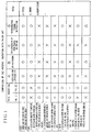
- Fig. 1 summarizes the differences of the present invention from the prior art.
- document (A) is the present inventor's prior application titled “High Efficiency Liquid Crystal Display” USP 5,355,189 and USP 5,537,171
- document (B) concerns "a display apparatus” (JP-A-6-230384)
- document (C) is a thesis titled “Compact Spatio-Chromatic Single-LCD Projection Architecture” by B.A. Lerson. et al, Asia Display. '95, P87 - P89
- document (D) is another thesis titled "Holographic Optical Element for Liquid Crystal Projector” by N. Ichikawa, Asia Display. '95, P727 - P729.
- FIG. 1 shows the function of the above-mentioned macroscopically flat diffracting plate means.
- reference numeral 1 denotes single plate type color liquid crystal panel means
- 2 denotes three-primary-color pixels
- 3 denotes light-input-side lenses forming three-position means for converging input three rays of each primary color coming from three directions to respective color positions at every trio-pixel pitch
- 23 denotes a block collectively representing a light source and collimator means.
- Reference numeral 5 denotes macroscopically flat diffracting plate means
- 6 denotes a diffraction grating formed on the outgoing plane of the diffracting plate means
- 7 denotes incident white light
- 7' denotes the direction of a zero-order light output from the diffracting plate.
- R, G and B represent red, green and blue light rays, but they may sometimes be referred to as R ray and so on for short.
- Reference numerals 8, 8' and 8" denote the G ray, R ray and B ray of the first-order diffracted light output from the diffracting plate.
- the angle ⁇ denotes the angle of deflection of the G ray by the diffracting plate
- ⁇ denotes a difference between the angle of deflection of the R ray and that of the G ray caused by the diffracting plate and is hereafter referred to as "R-G separation angle.”
- ⁇ 1 denotes the angle of incidence of the incident light to the diffraction grating 6
- ⁇ 1 denotes the angle of divergence of the incident light
- ⁇ 2 and ⁇ 2 denote the incident and diverging angles of the first-order diffracted green outgoing light
- ⁇ ' 2 denotes the incident angle of the red outgoing light
- P 0 denotes the pitch (period of array) of the diffraction grating.
- ⁇ G ⁇ 530 nm (G ray wavelength) ⁇ R ⁇ 610 nm (R ray wavelength) ⁇ ⁇ ⁇ ⁇ 2 ' - ⁇ 2 ⁇ ⁇ R - ⁇ G P 0 - l cos ⁇ 2 ⁇ ⁇ R - ⁇ G P 0 ⁇ 80 nm P 0 ⁇ ⁇ ⁇ G ⁇ ⁇ R - ⁇ G ⁇ 80 nm 530 nm ⁇ 0.15
- the magnitude of the G-R separation angle ⁇ is subordinately constrained by the green deflection angle ⁇ G , and limited to about 15% of ⁇ G .
- the diverging angle ⁇ 1 of the incident light is given by the following expression. ⁇ 1 ⁇ 2 A 0 A 1 ⁇ ⁇ 1MAX > 2 A 0 A 1
- Equation (8) holds. In actuality, however, the diverging angle distribution is not uniform, so that inequality (9) holds.
- the maximum value ⁇ 1MAX of ⁇ 1 is about 1.5 times as large as ⁇ 1 in most cases.
- the minimum projection light source proposed as a test case in the past is about 1.4 mm ⁇ and therefore the surface area is n (1.4 mm) 2 , namely, about 6.3 (mm) 2 .
- the surface area of the ordinary projection light source is about 25 (mm) 2 .
- the area of the diffracting plate is substantially equal to the area of the liquid crystal panel, and the diffracting plate of the maximum size for projection use has an opposite angle of about 6.5" and an area of 13,000 (mm)2.
- the deflection angle ⁇ G it is very difficult in the prior art to set the deflection angle ⁇ G to be 10° or less when the R-G separation angle is 0.05 rad or larger.
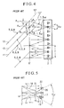
- Fig. 4 reference numerals 1 and 2 denote the same things as have been described, 11, 12 and 13 denote incident light rays, 11', 12' and 13' denote the outgoing directions of zero-order light rays, and 6' denotes a modulated pitch macroscopically flat diffraction grating.
- the symbol ⁇ denotes the above-mentioned R-G separation angle
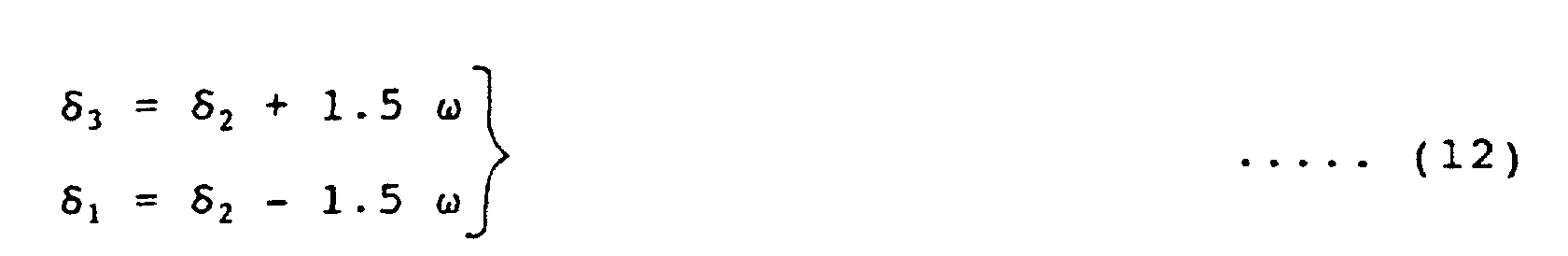
- T denotes a pitch of trio pixel array
- ⁇ 1 , ⁇ 2 and ⁇ 3 denote lower, middle and upper deflection angles of respective first-order diffraction G rays.
- the deflection angles are modulated differently at each pitch of trio pixel array. Therefore, in the conventional techniques (B) and (D) in Fig. 1, it is implicitly proposed to modulate the pitch of the diffraction grating according to the above-mentioned equation (1). Therefore, from the relation in Fig. 1 and equation (1), the relation of the following expression needs to be satisfied.
- P 01 , P 02 and P 03 are the pitches of those portions of the diffraction grating which correspond to the ⁇ 1 , ⁇ 2 and ⁇ 3 .
- P 03 ⁇ ⁇ G ⁇ 3 ⁇ G ⁇ 2 + 1.5 ⁇ ⁇ ⁇ G 8.1 ⁇ ⁇ 0.8 P 02 ⁇ P 01 P 03 ⁇ 1.6
- ⁇ 01 and ⁇ 03 are R-G separation angles by those portions of the diffraction grating which correspond to ⁇ 1 and ⁇ 3 in Fig. 4.
- the relation represented by the above expression is shown in Fig. 5.
- the value is 1.0 instead of 1.6, all three rays, including the red ray and the blue ray, besides the green ray, are matched (coincide) with the liquid crystal elements. However, because the above value is 1.6, the red ray and the blue ray are not matched with the target liquid crystal elements as shown in Fig. 5. In other words, the utilization efficiency of the red and blue light ray deteriorates.
- Fig. 5 shows only one period of the trio pixel array.
- reference numerals 2 and 6' denote same things as already described, 14, 15 and 16 denote the first order diffracted G rays, 17, 18 and 19 denote the first order diffracted R rays, and 20, 21 and 22 denote the first order B rays.
- R and B component rays of the principal ray striking the center of each pitch of the diffraction grating 6' are both correctly incident on the target pixels.
- the marginal rays corresponding to both end portions of each pitch are unable to be incident on the target pixels due to deviation loss.
- the problem has become evident that the convergence of R and B rays to the red and blue pixels by the diffraction grating is not compatible as mentioned in Item 3.4 in Fig. 1. More specifically, the problem includes the deterioration of the transmission efficiency of R and B rays and the deterioration of chromatic purity owing to color mixture.
- a further conventional technique is shown in WO-A-95/22773.
- This technique includes the provision of a diffraction grating at microscopic level and an overlay of a prism-like macro periodic structure.
- thermonuclear power generation can be realized easily.
- An object of the present invention is to provide a single plate type color liquid crystal display apparatus featuring the improved transmission efficiency.
- Another object of the present invention is to provide a liquid crystal display capable of having the deflection angle ⁇ G by the light diffracting means of 10° (0.17 rad) or less and the R-G separation ⁇ of 3° (0.05 rad) or larger (in other words, thus overcoming the constraint by equation (4)).
- a further object of the present invention is to provide a novel optical system capable of make compatible the convergence by the light diffracting means of rays to the target R, G and B pixels (thus overcoming the constraint in equation (16)).
- Yet another object of the present invention is to provide a new-fangled optical system for reducing nearly in half a substantial increase of the light diverging angle caused by the R-G separation angle by the light diffracting means.
- a still further object of the present invention is to provide a liquid crystal display apparatus for improved picture quality.
- An additional object of the present invention is to provide a liquid crystal display apparatus of less power consumption type by improving the light utilization efficiency.
- Another object of the present invention is to provide a compact space-saving or light-weight liquid crystal display apparatus.
- both types [1] and [2] in Fig. 1 of the liquid crystal display include common novel light diffracting means, and the novel light diffracting means is, at its macroscopic level, a three-dimensional unflat plate form with a macro structural periodicity having at least either macro prisms or a macro lenticular face, together with multi-stepped diffraction gratings at its microscopic level.
- the display apparatus is in a shape having prisms at its macroscopic level, and also includes light diffracting means having a diffraction grating formed on an oblique side face of each prism at its microscopic level.
- the light diffracting means serves to cancel its angle of deflection by its macro prisms. Therefore, the R-G separation angle can be set at 3° or larger, and the deflection angle of the G ray can be set at 20° or less. The reduction of the deflection angle is effective in reducing the volume of the cabinet for housing the optical system.
- the light diffracting means is formed with a macro lenticular face, and the pitch of array of the lenticular elements is selected so as to be equal to the pitch of trio pixel array of the liquid crystal panel.
- the lenticular structure enables the G rays emerging from the diffraction grating to converge to the G pixels.
- the pitch of the diffraction grating array is set to obtain an adequate G-R separation angle ⁇ independently of the modulated pitch of the diffraction direction of G rays. Therefore, by overcoming the condition of constraint in the above-mentioned equation (16), it becomes possible to make compatible the convergence of R, G and B rays to the target pixels by the light diffracting means.
- the light transmission efficiency and the chromatic purity can be improved, and therefore, and therefore the picture quality can be enhanced.
- collimator means for reducing the light diverging angle is installed at the rear of the diffraction grating.
- the focal plane of the collimator means is selected so as to substantially coincide with the diffraction grating (accuracy within about ⁇ 30%). Therefore, the rays incident on the same point of the diffraction grating emerge as parallel rays from the collimator means. Consequently, the light diverging angle can be decreased.
- projection lens means is placed at the rear of the liquid crystal panel means, this method is effective in reducing the aperture and the weight of the projection lens means.
- the liquid crystal panel can reproduce high quality images with high contrast ratio the better at smaller diverging angles of the rays passing therethrough. Accordingly, the picture quality can be improved by the function of the collimator means for reducing the light diverging angle.
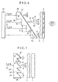
- Fig. 6 shows a first embodiment of the present invention.
- reference numeral 1 denotes the single plate type color liquid crystal panel means already mentioned
- 3 denotes the three-position means already mentioned
- 23 denotes the block including a light source and collimator means already mentioned
- 25 denotes a white ray
- 26 denotes macro prism type diffracting means including at a macroscopic level prisms and at a microscopic level a diffraction grating formed on the oblique side face of each prism.
- Reference numeral 27 denotes a diffraction grating
- ⁇ denotes the vertical angle of the macro prism
- P 0 denotes the pitch of the diffraction grating array
- P denotes the projection of P 0 as viewed from the emerging direction of the first order diffracted ray, that is, the projection of the pitch which is measured in a plane at right angles with the traveling direction of the light, and which is substantially equal to P 0 cos ⁇ .
- the h denotes the height of a unit step as a component part of the diffraction grating
- 24 and 24' denotes the side faces of the row of prisms, the respective side faces 24 and 24' being so arranged as to be substantially parallel with or at right angles with the incident white light 25.
- the Q denotes the arrangement pitch of the row of macro prisms as viewed from the direction of the incident light, in other words, the projection of the pitch in the light traveling direction.
- the 8, 8' and 8" denotes G, R and B rays of the first order diffracted output rays, and ⁇ denotes the R-G separation angle.
- ⁇ 0 denotes the characteristic wavelength of this system
- n denotes the refractive index of the medium forming the macro prism type light diffracting means.
- the first order diffracted ray of wavelength ⁇ 0 passes at zero deflected angle through the light diffracting means. This is because the effective optical path difference at each unit step of the diffraction grating is a difference of (n-1)h between nh in the medium and h in the air and the difference is equal to the wavelength ⁇ 0 according to equation (17).
- Fig. 6 exemplifies a case where ⁇ 0 is equated with ⁇ G .
- the ⁇ R , ⁇ B or any specific wavelength of the infrared or ultraviolet region can be selected for the ⁇ 0 in a range that the selected wavelength satisfies equation (21).
- Equation (18) expresses the relation between the R-B separation angle ⁇ and the projected pitch P of diffraction grating.
- the R-G separation angle 3° or larger ( ⁇ of 0.05 rad or more), which is aimed at in the present invention, it is required to set the projected pitch P at 1.6 ⁇ m or less according to equation (18).
- Inequality (19) is the condition for limiting the diffraction by the macro prism to less than 0.01 rad. By satisfying this condition, the light diverging angle can be prevented from increasing, so that a liquid crystal display with reduced color mixture between R, G and B and superior picture quality can be realized.
- Inequalities (20) and (21) are the conditions for limiting the deflected angle of the G ray to less than 10°.
- Inequality (22) shows the condition for limiting the deflected angle of the G ray to less than 10° when the R-B separation angle is 0.05 rad or less, which is aimed at in this embodiment.
- the conditions in this embodiment are arranged for generalizing purposes as follows.
- the L is a positive integer of 1 or more or 3 or less.
- the value of L was 1.
- the L value of 4 or larger is not recommended. The reason is that if the L value is 4 or larger, the diffraction efficiency declines intolerably, though detailed description is omitted here. If the value of L is 1, 2 or 3, these values may be used in this embodiment. In such a case, the L-th order diffracted light is used.
- FIG. 7 A second embodiment of the present invention is shown in Fig. 7.
- reference numerals 1, 3, 8, 24, 24', 25, 26 and 27 designate the same things as those mentioned above.
- the macro prism type light diffracting means 26 has a macro prism provided on the light input side thereof and a diffraction grating 27 formed on the light output side thereof, whereas in Fig. 7, both the macro prism and the diffraction grating 27 are provided on the light output side of the macro prism type diffraction grating means 26.
- the macro prism type light diffracting means 26 and the diffraction grating 27 may be manufactured separately and joined together later.
- Fig. 8 shows a third embodiment of the present invention.
- reference numerals 1, 2, 24, 24', and 25 designate the same things as those described above.
- Reference numeral 26' denotes macro lenticular light diffracting means
- 27' denotes diffraction gratings.
- the arrangement pitch Q of macro lenticular elements is set to be equal to the pitch of trio pixel array of the liquid crystal panel means 1.
- the third embodiment differs from the second embodiment in Fig. 7 in that the oblique side faces of the row of macro prisms are curved in a lenticular structure. Therefore, the height h of the unit steps of the diffraction grating is not uniform, so that the height h is modulated periodically.
- L denotes integers of 1 to 3
- n denotes the refractive index of the medium of the liquid crystal panel means and the light diffracting means
- D 0 denotes the distance from the surface of the liquid crystal panel means to the row of pixels.
- T denotes the trio pixel period
- P(x) denotes the projected pitch (the pitch measured in the direction at right angles with the light traveling direction)
- ⁇ R and ⁇ G denote wavelengths of the R and G rays
- ⁇ G denotes the deflected angle of the G ray.
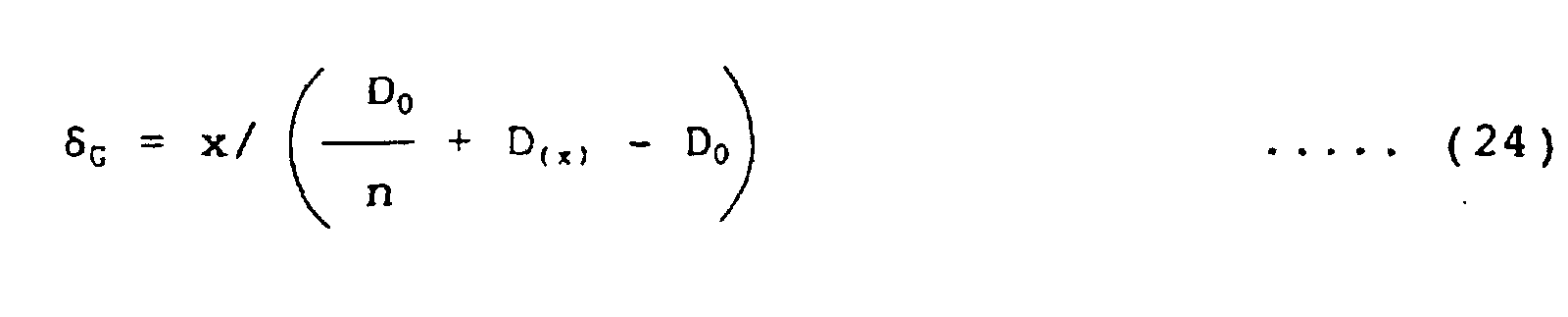
- Equation (23) shows the condition for setting the effective optical path difference (n - 1)h(x) of each step of the grating for G ray so that the L-th order diffracted G ray travels in the direction of the G pixel.
- the denominator, D 0 /n + D(x) - D 0 , of the last term of equation (23) is the effective optical path length from the diffraction grating to the pixel row of the liquid crystal panel, and the numerator x is the distance in the x direction measured from the center of the G pixel. The ratio between them is equal to the deflected angle ⁇ G of the G ray.
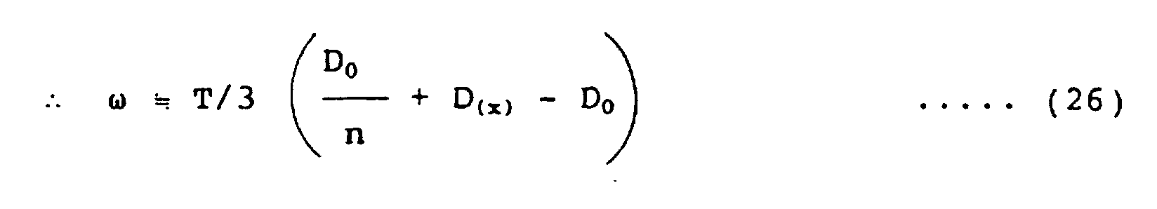
- Equation (25) shows the condition for making the R-G separation angle equal to ⁇ . Inequality (19) has already been described.
- the diverging angle of output from the liquid crystal panel in the third embodiment has a large value of 5 ⁇ as shown in Fig. 8. This value is equal to the output diverging angle of 5 ⁇ in the prior art in Fig. 5 and corresponds to the total value of ⁇ and ⁇ 1.5 ⁇ in Fig. 4.
- a fourth embodiment for decreasing the output diverging angle to about 3 ⁇ is shown in Fig. 9.
- reference numerals other than 4 designate the same things as shown in Fig. 8., 4 denoting lenticular lenses forming the divergence-reducing collimator means.
- the focal plane of the collimator means is selected so as to substantially coincide with the diffraction grating face 27' (accuracy within ⁇ 30%).
- the height ⁇ D of the macro prism is expressed so to be about the same as the distance to the pixel face, D 0 , but in actuality ⁇ D is less than about 1/5 of D 0 . Therefore, the above setting is possible.
- the light rays emerging from the same point of the diffraction grating face 27' become parallel rays when they are output from the collimator means. Therefore, the ray emerging from each center 30 of the macro prism face, namely, the principal ray is converted into parallel rays perpendicular to the liquid crystal panel face.
- the marginal rays 30' and 30" are converted respectively into parallel rays at angles of ⁇ 1.5 ⁇ to the normal of the liquid crystal panel. Consequently, the diverging angle of output rays from the panel is reduced to about 3 ⁇ (reduced to about a half of 5 ⁇ ). With this, description of Fig. 9 is finished.
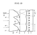
- a fifth embodiment by which to further reduce the diverging angle is shown in Fig. 10.
- 31 denotes black stripe means, which are formed right behind the light output face of or on the light input face 24' of the light diffracting means 26' as indicated by 31". Faces 24" are located along the light traveling direction and may be formed inclined as illustrated. (In some cases, the faces 24" thus inclined facilitate the manufacture of the light diffracting means 26'.)
- the parts other than mentioned in this paragraph are the same as those shown in Fig. 9.
- the width of the black stripes is set to be about 2/3 of the trio pixel period T, the diverging angle of the emerging rays from the liquid crystal panel can be reduced to 2/3 that of the case where no black stripes are used, more specifically, reduced to about 2 ⁇ as shown in Fig. 10.
- the light transmission efficiency is reduced in proportion to the black stripe rate, but the diverging angle of the output light can be decreased, and owing to the color mixture prevention and the improved contrast ratio, the picture quality improves.
- the fifth embodiment comprises single plate type color liquid crystal panel means, three-direction means, three-position means, and black stripe row means, in other words, the diffraction grating is not a requirement. With this, description of Fig. 10 is finished.
- the above-described embodiments are of a type using the pixel array of a trio of RGB, RGB, and so on. Description will now be made of an applied example using a quad type pixel array of RGBG, RGBG and so on.
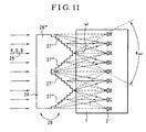
- Fig. 11 shows a quad type applied example as a sixth embodiment of the present invention.
- reference numeral 27" denotes diffraction gratings formed on oblique side faces of the macro prisms, which are inclined in the reverse direction to the gratings 27' already described, and 2' denotes a row of quad-arranged pixels.
- the color rays can be collected to the quad-arranged pixels.
- the brightness contribution rates of the R, G and B component rays forming a white ray are roughly 30%, 60% and 10%. Therefore, there is an advantage that the quad pixel array enables high-resolution images to be realized with a smaller total number of pixels. It ought to be noted that the output diverging angle in the sixth embodiment is about 4 ⁇ . Modifications shown in Figs. 9 and 10, which were made to Fig. 8, can also be applied to Fig. 11, and similar modifications are included in the present invention.
- the micro-level faces of the diffraction grating of each prism respectively include the faces substantially parallel with and the faces substantially at right angles with the light traveling direction, but the faces at right angles with the light traveling direction may be inclined according to the deflected angle of G rays so that the rays have the same wavefront.
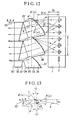
- Fig. 12 shows a seventh embodiment, which belongs to Type II of the present invention in Fig. 1 already described.
- Fig. 12 the parts designated as 1, 2, and 25 are the same as have been described, 32 denotes linear Fresnel lens means, 32' denotes the light input face of this Fresnel lens means, 32" denotes a prism face formed on the light output face of the Fresnel lens means, 33 denotes light diffracting means having macro prisms combined with lenticular faces at its macroscopic level, and includes diffraction gratings at its microscopic level, 34 denotes a prism face formed on the light input face of the diffracting means, dotted lines 36 denote macro prisms combined with lenticular faces, 37 denotes diffraction gratings, and 38 denotes discontinuation faces of the macro prisms.
- the input white light (25) is refracted at the prism faces 32", 34), and at a deflection angle of ⁇ 1 ' is incident on the diffraction gratings (37).
- Equation (25') and (26) are the same as equations (25) and (26) mentioned above.
- Equation (27), which indicates the output direction of G ray, is the same as equation (24) mentioned above.
- the left side member (nh 1 - h 2 ) of equation (28) expresses the effective optical path difference at each step of the diffraction grating.
- Equation (33) by periodically modulating the effective unit optical path difference as a function of x, the G output rays can be directed toward the G pixels. This modulation can be achieved by keeping compatibility with the constraint condition equation (25') showing the definition of the R-G separation angle. Therefore, Items 3.3 and 3.4 in Fig. 1 already described can be satisfied at the same time. Equation (34) shows the condition to be satisfied by the prism faces 32" and 34. Equation (35) is a condition for specifying the microscopic-level prism angle of the diffraction grating. To satisfy this condition is effective for increasing the diffraction efficiency close to 1.
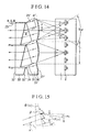
- Fig. 14 shows an eighth embodiment of the present invention, which belongs to Type II in Fig. 1 already mentioned.
- the parts designated by 1, 2, 25, 32, 32', 32", 34, and 35 are the same as have been described above
- 33' denotes light diffracting means has a lenticular structure at its macroscopic level, and includes diffraction gratings at its microscopic level
- 36' denotes a dotted line indicating the macro lenticular shape
- 37' denotes diffraction gratings.
- Fig. 15 is a fragmentary view on an enlarged scale.
- each lens formed by combining a prism face 34 and a macro lenticular shape 36' is a macro lenticular lens.
- a diffraction grating 27 may be joined with an adhesive to the outer surface of the macro lenticular shape 36'.
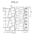
- Fig. 16 shows a ninth embodiment of the present invention.
- this ninth embodiment is formed by adding field lens means 4 for reducing the light diverging angle to Fig. 14, to thereby decrease the diverging angle of rays output from the panel to 3 ⁇ .
- the focal plane of the field lens means is arranged to substantially coincide with the position of the diffraction gratings 37'.
- a modification is possible, which is formed by adding the black stripe means 31 shown in Fig. 10 to this ninth embodiment, and this modification is included in the present invention.
- the collimator means 4 may be provided on the light input face 4" of the panel means.
- the diffraction gratings 37' may be provided on the face 37". With this, description of Fig. 16 is finished.
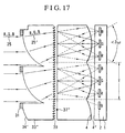
- Fig. 17 shows a tenth embodiment of the present invention.
- reference numeral 33" denotes light diffracting means having macro prisms combined with a lenticular face
- 34' denotes a shape formed of macro prisms combined with a lenticular face formed on the light input face of the diffracting means
- 31 denotes black stripe means
- 39 denotes diffraction grating.
- the operation principle of this tenth embodiment may be understood from the arrow-marked light rays and the descriptions of the drawings shown above.
- the focal plane of the collimator means for reducing the light diverging angle is arranged so as to substantially coincide with the position of the diffraction grating 39.
- the provision of the black stripe means 31 increases light loss, but there is an advantage that the diverging angle of output from the panel can be reduced to less than 3 ⁇ .
- Fig. 18 is a graph showing the applicable range of the eighth and ninth embodiments of the present invention shown in Figs. 14 and 16.
- Fig. 18 graphically depicts equation (37) and corresponds to a case where the material has a normal refractive index value of 1.5.
- ⁇ 1 ' to about 0.6 or less rad is required to practically realize the prism components. Therefore, the applicable range of the eighth and ninth embodiments is the range indicated by 50 in Fig. 8. This range fully covers the range shown in inequality (10) mentioned above.
- the collimator means included in the block 23 has chromatic aberration, by correcting the value of R-G separation angle ⁇ according to the amount of the chromatic aberration at issue, the chromatic aberration can be compensated.
- a line light source is normally used for the light source means in the block 23.
- the collimator means is formed by combining a light guide plate, a row of prisms, black stripes, lenticular lenses, and so on.
- the present invention can be applied if about 0.3 to 0.6 rad is selected for the value of the R-G separation angle ⁇ . With this, description of the preferred embodiments of the present invention is finished.
- the array pitch of macro lenticular elements is substantially equal to the array pitch of the liquid crystal panel means. Therefore, the thermal expansion coefficients of the materials need to be matched to that of the liquid crystal panel means.
- the liquid crystal panel means is normally made of a glass material. Accordingly, in the embodiments of the present invention, too, a glass material is ordinarily used as the material of the macro lenticular type light diffracting means.
- the diffraction grating and the lenticular elements provided at the surface of the macro lenticular type light diffracting means are formed of a glass or resin material, but for general applications, a ultraviolet-light-hardening type resin material is recommended.
- each embodiment can be formed by taking into consideration a fact that the effective optical path difference nh 1 - h 2 changes to nh 1 - n 2 h 2 .
- the liquid crystal display apparatus is not limited to the direct viewing type, but may be applied to the projection type and the optical fiber type.
- Fig. 19 shows an application of the present invention to the projection type display.
- reference numeral 40 denotes a block, typical of the embodiments described above, which includes the above-mentioned macro prism type or macro lenticular type light diffracting means in the present invention.
- Reference numeral 23 denotes a block including light source means and collimator means, 1 denotes liquid crystal panel means, 41 denotes projection lens means, and 42 denotes screen means.
- Fig. 20 shows an application of the present invention to the optical fiber type display.
- reference numeral 43 denotes optical fiber
- 44 denotes a fiber light input end
- 45 denotes a fiber light output end plus fiber screen means.
- a single plate type color liquid crystal display apparatus with improved light transmission efficiency which is capable of separating the input white light into three primary colors traveling in different directions, and guiding the three color rays to the corresponding pixels of the single plate liquid crystal panel means.
- the first (Fig. 6) and the second (Fig. 7) embodiments of the present invention it is possible to set the R-G separation angle by the light diffracting means at 0.05 rad or more and the deflected angle of the green ray at 0.17 rad or less, making it possible provide a compact optical system.
- the third to tenth embodiments of the present invention it is possible to achieve the compatibility of the converging actions by the light diffracting means into the R, G and B pixels, with the result that a liquid crystal display apparatus can be provided which has reduced color mixture, hence high picture quality, and less required power consumption.
Description
- The present invention relates to a single plate type color liquid crystal display apparatus featuring high efficiency achieved by utilizing light diffraction, and other products in which this invention is applied, and more particularly to a projection type display apparatus.
- To help the present invention better understood, Fig. 1 summarizes the differences of the present invention from the prior art. In Fig. 1, document (A) is the present inventor's prior application titled "High Efficiency Liquid Crystal Display" USP 5,355,189 and USP 5,537,171, document (B) concerns "a display apparatus" (JP-A-6-230384), document (C) is a thesis titled "Compact Spatio-Chromatic Single-LCD Projection Architecture" by B.A. Loiseaux. et al, Asia Display. '95, P87 - P89, and document (D) is another thesis titled "Holographic Optical Element for Liquid Crystal Projector" by N. Ichikawa, Asia Display. '95, P727 - P729.
- These techniques of the prior art, as indicated in Item 2.1 in Fig. 1, use diffracting plate means which are formed as a flat plate as viewed at a macroscopic level and also include diffracting plate means minutely formed at a microscopic level. Fig. 2 shows the function of the above-mentioned macroscopically flat diffracting plate means.
- In Fig. 2, reference numeral 1 denotes single plate type color liquid crystal panel means, 2 denotes three-primary-color pixels, 3 denotes light-input-side lenses forming three-position means for converging input three rays of each primary color coming from three directions to respective color positions at every trio-pixel pitch, 23 denotes a block collectively representing a light source and collimator means. For the functions of the above-mentioned components, refer to the descriptions in technique (A) in prior art in Fig. 1. Reference numeral 5 denotes macroscopically flat diffracting plate means, 6 denotes a diffraction grating formed on the outgoing plane of the diffracting plate means 5, 7 denotes incident white light, and 7' denotes the direction of a zero-order light output from the diffracting plate. Normally, such a structure of the diffraction grating is selected as to minimize the power of the zero-order light. R, G and B represent red, green and blue light rays, but they may sometimes be referred to as R ray and so on for short. Reference numerals 8, 8' and 8" denote the G ray, R ray and B ray of the first-order diffracted light output from the diffracting plate. The angle δ denotes the angle of deflection of the G ray by the diffracting plate, and ω denotes a difference between the angle of deflection of the R ray and that of the G ray caused by the diffracting plate and is hereafter referred to as "R-G separation angle."
- Next, with regard to Item 3.2 in Fig. 1, the reason why the deflection angle of G ray has to be 20 or larger in the prior art will be described with reference to Fig. 3.
- In Fig. 3, reference numerals 6, 7 and 8 and δ and ω denote the same things as have been described. The symbol α1 denotes the angle of incidence of the incident light to the diffraction grating 6, ε1 denotes the angle of divergence of the incident light, α2 and ε2 denote the incident and diverging angles of the first-order diffracted green outgoing light, α'2 denotes the incident angle of the red outgoing light, and P0 denotes the pitch (period of array) of the diffraction grating.
- In compliance with the principle of light diffraction, the following equation holds.
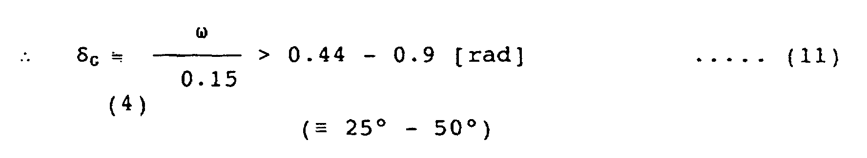
λR ≒ 610 nm (R ray wavelength) - That is to say, it is known that the magnitude of the G-R separation angle ω is subordinately constrained by the green deflection angle δG, and limited to about 15% of δG.
- On the other hand, attention needs to be paid to a fact that the relation between the diverging angles ε1 and ε2 can be obtained by differentiating equation (1).
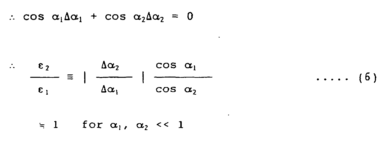
- To separate the G ray and the R ray, the following condition must be satisfied.
- Generally, according to the law of energy conservation, if the effective surface area of a Lambertian light source is designated by A0 and the vertical projection of the incident area of the diffracting plate is designated by A1, the diverging angle ε1 of the incident light is given by the following expression.
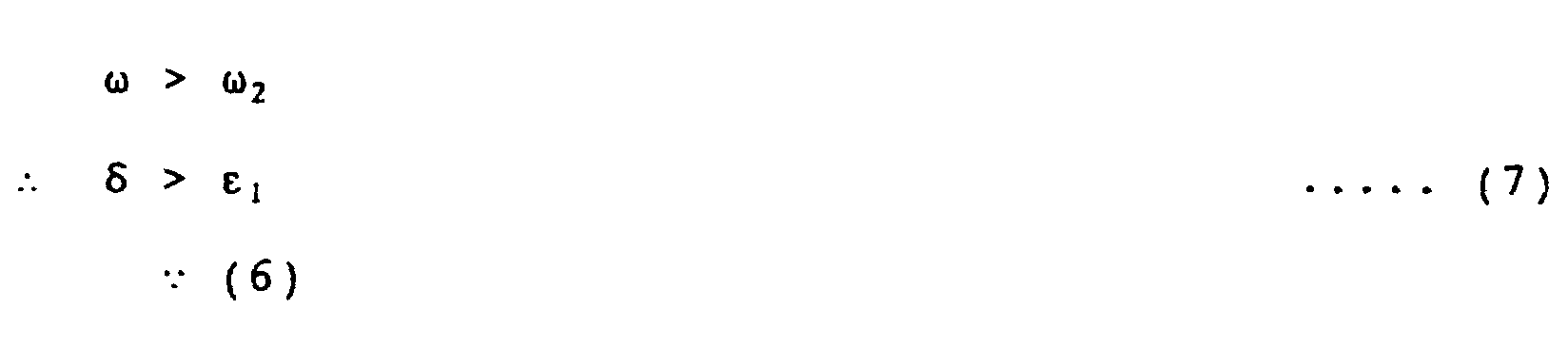
- If the diverging angle distribution is uniform, equation (8) holds. In actuality, however, the diverging angle distribution is not uniform, so that inequality (9) holds. Normally, the maximum value ε1MAX of ε1 is about 1.5 times as large as ε1 in most cases. The minimum projection light source proposed as a test case in the past is about 1.4 mm and therefore the surface area is n (1.4 mm)2, namely, about 6.3 (mm)2. The surface area of the ordinary projection light source is about 25 (mm)2. On the other hand, the area of the diffracting plate is substantially equal to the area of the liquid crystal panel, and the diffracting plate of the maximum size for projection use has an opposite angle of about 6.5" and an area of 13,000 (mm)2. By substituting those values into expression (9), we have the following expression.
- As is obvious from the above expression, it is very difficult in the prior art to set the deflection angle δG to be 10° or less when the R-G separation angle is 0.05 rad or larger.
- From the above explanation, the description of the prior art in Item 3.2 in Fig. 1 can be understood.
- The ground for the description of the prior art in Item 3.4 in Fig. 1 will be demonstrated in the following.
- Before that, as the first step, it is necessary to describe the principle of prior art techniques (B) and (D) related to Item 3.3 in Fig. 1. Description will be made with reference to Fig. 4.
- In Fig. 4, reference numerals 1 and 2 denote the same things as have been described, 11, 12 and 13 denote incident light rays, 11', 12' and 13' denote the outgoing directions of zero-order light rays, and 6' denotes a modulated pitch macroscopically flat diffraction grating. The symbol ω denotes the above-mentioned R-G separation angle, T denotes a pitch of trio pixel array, and δ1, δ2 and δ3 denote lower, middle and upper deflection angles of respective first-order diffraction G rays. As illustrated, the deflection angles are modulated differently at each pitch of trio pixel array. Therefore, in the conventional techniques (B) and (D) in Fig. 1, it is implicitly proposed to modulate the pitch of the diffraction grating according to the above-mentioned equation (1). Therefore, from the relation in Fig. 1 and equation (1), the relation of the following expression needs to be satisfied.
- In the following expressions, P01, P02 and P03 are the pitches of those portions of the diffraction grating which correspond to the δ1, δ2 and δ3.

- By the above analysis, the following could be clarified. Specifically, if the pitch of the diffraction grating is modulated in synchronism with the period of a trio pixel array to satisfy equations (13) and (14), the diffraction grating 6' can be made to also play the role of the three-position means 3 in Fig. 2 as long as the G ray is concerned. With this, description of the result of clarification by the present inventor of the principles of the conventional techniques related to Item 3.3 in Fig. 1 is finished.
- As the second step, description will proceed to the conventional technique in Item 3.3 in Fig. 1. In the macroscopically flat plate diffraction grating, there is a condition of constraint shown in equation (4), which has been described above. From equations (4), (1) and (15), it is inevitable that an unfavorable expression given below holds.
- In the above equation, ω01 and ω03 are R-G separation angles by those portions of the diffraction grating which correspond to δ1 and δ3 in Fig. 4. The relation represented by the above expression is shown in Fig. 5.
- If in the above expression the value is 1.0 instead of 1.6, all three rays, including the red ray and the blue ray, besides the green ray, are matched (coincide) with the liquid crystal elements. However, because the above value is 1.6, the red ray and the blue ray are not matched with the target liquid crystal elements as shown in Fig. 5. In other words, the utilization efficiency of the red and blue light ray deteriorates.
- Fig. 5 shows only one period of the trio pixel array. In Fig. 5, reference numerals 2 and 6' denote same things as already described, 14, 15 and 16 denote the first order diffracted G rays, 17, 18 and 19 denote the first order diffracted R rays, and 20, 21 and 22 denote the first order B rays. As is clear from Fig. 5, R and B component rays of the principal ray striking the center of each pitch of the diffraction grating 6' are both correctly incident on the target pixels. On the other hand, the marginal rays corresponding to both end portions of each pitch are unable to be incident on the target pixels due to deviation loss. Therefore, in the techniques (B) and (D) in the prior art, the problem has become evident that the convergence of R and B rays to the red and blue pixels by the diffraction grating is not compatible as mentioned in Item 3.4 in Fig. 1. More specifically, the problem includes the deterioration of the transmission efficiency of R and B rays and the deterioration of chromatic purity owing to color mixture.
- A further conventional technique is shown in WO-A-95/22773. This technique includes the provision of a diffraction grating at microscopic level and an overlay of a prism-like macro periodic structure.
- In the course of the above description, the constraint on the size of a usable light source was mentioned, and it is vitally important to take this constrain into consideration.
- This is because not only a point light source such as can be expressed as a mathematical concept of a point does not exist in reality, but it should be understood that a point light source is incapable of existing according to the principle of uncertainty or the second law of thermodynamics. A premise including only one wrong hypothesis would lead to illusions such that innumerable impossibilities are taken for possibilities. For example, if a viability of a point light source is supposed, from this it may be deduced that thermonuclear power generation can be realized easily.
- Therefore, the above-mentioned constraint on the size of the light source is an important matter requiring consideration.
- The present invention could not have been possible without the above-mentioned result of clarification by the present inventor. On account of this, this subject will first be summarized in the following.
- An object of the present invention is to provide a single plate type color liquid crystal display apparatus featuring the improved transmission efficiency.
- Another object of the present invention is to provide a liquid crystal display capable of having the deflection angle δG by the light diffracting means of 10° (0.17 rad) or less and the R-G separation ω of 3° (0.05 rad) or larger (in other words, thus overcoming the constraint by equation (4)).
- A further object of the present invention is to provide a novel optical system capable of make compatible the convergence by the light diffracting means of rays to the target R, G and B pixels (thus overcoming the constraint in equation (16)).
- Yet another object of the present invention is to provide a new-fangled optical system for reducing nearly in half a substantial increase of the light diverging angle caused by the R-G separation angle by the light diffracting means.
- A still further object of the present invention is to provide a liquid crystal display apparatus for improved picture quality.
- An additional object of the present invention is to provide a liquid crystal display apparatus of less power consumption type by improving the light utilization efficiency.
- Another object of the present invention is to provide a compact space-saving or light-weight liquid crystal display apparatus.
- In order to achieve the above objects the invention as defined in appended claim 1 is provided. In preferred embodiments of the present invention, both types [1] and [2] in Fig. 1 of the liquid crystal display include common novel light diffracting means, and the novel light diffracting means is, at its macroscopic level, a three-dimensional unflat plate form with a macro structural periodicity having at least either macro prisms or a macro lenticular face, together with multi-stepped diffraction gratings at its microscopic level.
- In an embodiment of the present invention formed to achieve the above object, the display apparatus is in a shape having prisms at its macroscopic level, and also includes light diffracting means having a diffraction grating formed on an oblique side face of each prism at its microscopic level.
- The light diffracting means serves to cancel its angle of deflection by its macro prisms. Therefore, the R-G separation angle can be set at 3° or larger, and the deflection angle of the G ray can be set at 20° or less. The reduction of the deflection angle is effective in reducing the volume of the cabinet for housing the optical system.
- In another embodiment of the present invention, the light diffracting means is formed with a macro lenticular face, and the pitch of array of the lenticular elements is selected so as to be equal to the pitch of trio pixel array of the liquid crystal panel. The lenticular structure enables the G rays emerging from the diffraction grating to converge to the G pixels. The pitch of the diffraction grating array is set to obtain an adequate G-R separation angle ω independently of the modulated pitch of the diffraction direction of G rays. Therefore, by overcoming the condition of constraint in the above-mentioned equation (16), it becomes possible to make compatible the convergence of R, G and B rays to the target pixels by the light diffracting means. Thus, the light transmission efficiency and the chromatic purity can be improved, and therefore, and therefore the picture quality can be enhanced.
- In a further embodiment of the present invention, collimator means for reducing the light diverging angle is installed at the rear of the diffraction grating. The focal plane of the collimator means is selected so as to substantially coincide with the diffraction grating (accuracy within about ±30%). Therefore, the rays incident on the same point of the diffraction grating emerge as parallel rays from the collimator means. Consequently, the light diverging angle can be decreased. In an application that projection lens means is placed at the rear of the liquid crystal panel means, this method is effective in reducing the aperture and the weight of the projection lens means. Generally, the liquid crystal panel can reproduce high quality images with high contrast ratio the better at smaller diverging angles of the rays passing therethrough. Accordingly, the picture quality can be improved by the function of the collimator means for reducing the light diverging angle.
-
- Fig. 1 is a table comparing the differences in object, means, and effects between the present invention and the prior art;
- Fig. 2 is a schematic structure diagram showing the basic structure of the liquid crystal display apparatus in the prior art;
- Fig. 3 is a light ray diagram showing the function of the macroscopically flat diffracting plate in Fig. 2;
- Fig. 4 is a schematic light ray diagram showing the operation principle of the prior-art modulated pitch type macroscopically flat diffracting plate;
- Fig. 5 is a schematic light ray diagram for explaining the problem of the prior-art modulated pitch type macroscopically flat diffracting plate;
- Fig. 6 is a schematic structure diagram showing a first embodiment (Type I) including macro prism diffracting means according to the present invention;
- Fig. 7 is a schematic structure diagram showing a second embodiment (Type I) including macro prism diffracting means according to the present invention;
- Fig. 8 is a schematic structure diagram showing a third embodiment (Type II) including macro prisms combined with macro prism type diffracting means according to the present invention;
- Fig. 9 is a schematic structure diagram showing a fourth embodiment (Type II) including macro prisms combined with macro prism type diffracting means according to the present invention;
- Fig. 10 is a schematic structure diagram showing a fifth embodiment (Type II) including macro prisms combined with macro prism type diffracting means according to the present invention;
- Fig. 11 is a schematic structure diagram showing a sixth embodiment (Type II) including macro prisms combined with macro prism type diffracting means according to the present invention;
- Fig. 12 is a schematic structure diagram showing a seventh embodiment (Type II) including macro prisms combined with macro prism type diffraction grating according to the present invention;
- Fig. 13 is a fragmentary view, on an enlarged scale, of Fig. 12;
- Fig. 14 is a schematic structure diagram showing an eighth embodiment (Type II) including macro lenticular light diffracting means according to the present invention;
- Fig. 15 is a fragmentary view, on an enlarged scale, of Fig. 14;
- Fig. 16 is a schematic structure diagram showing a ninth embodiment (Type II) including macro lenticular light diffracting means according to the present invention;
- Fig. 17 is a schematic structure diagram showing a tenth embodiment (Type II) including macro lenticular light diffracting means according to the present invention;
- Fig. 18 is a graph showing the applicable range of the eighth and ninth embodiments according to the present invention;
- Fig. 19 is a schematic structure diagram showing an application of the present invention to a projection type display apparatus; and
- Fig. 20 is a schematic structure diagram showing an application of the present invention to an optical fiber display apparatus.
-
- Fig. 6 shows a first embodiment of the present invention.
- In Fig. 6, reference numeral 1 denotes the single plate type color liquid crystal panel means already mentioned, 3 denotes the three-position means already mentioned, 23 denotes the block including a light source and collimator means already mentioned, 25 denotes a white ray, 26 denotes macro prism type diffracting means including at a macroscopic level prisms and at a microscopic level a diffraction grating formed on the oblique side face of each prism. Reference numeral 27 denotes a diffraction grating, denotes the vertical angle of the macro prism, P0 denotes the pitch of the diffraction grating array, P denotes the projection of P0 as viewed from the emerging direction of the first order diffracted ray, that is, the projection of the pitch which is measured in a plane at right angles with the traveling direction of the light, and which is substantially equal to P0cos . The h denotes the height of a unit step as a component part of the diffraction grating, 24 and 24' denotes the side faces of the row of prisms, the respective side faces 24 and 24' being so arranged as to be substantially parallel with or at right angles with the incident white light 25. The Q denotes the arrangement pitch of the row of macro prisms as viewed from the direction of the incident light, in other words, the projection of the pitch in the light traveling direction. The 8, 8' and 8" denotes G, R and B rays of the first order diffracted output rays, and ω denotes the R-G separation angle. The operation principle of this embodiment will be described using the following expressions.
- In equation (17), λ0 denotes the characteristic wavelength of this system, n denotes the refractive index of the medium forming the macro prism type light diffracting means. The first order diffracted ray of wavelength λ0 passes at zero deflected angle through the light diffracting means. This is because the effective optical path difference at each unit step of the diffraction grating is a difference of (n-1)h between nh in the medium and h in the air and the difference is equal to the wavelength λ0 according to equation (17). Fig. 6 exemplifies a case where λ0 is equated with λG. The λR, λB or any specific wavelength of the infrared or ultraviolet region can be selected for the λ0 in a range that the selected wavelength satisfies equation (21).
- Equation (18) expresses the relation between the R-B separation angle ω and the projected pitch P of diffraction grating. To realize the R-G separation angle 3° or larger (ω of 0.05 rad or more), which is aimed at in the present invention, it is required to set the projected pitch P at 1.6 µm or less according to equation (18).
- Inequality (19) is the condition for limiting the diffraction by the macro prism to less than 0.01 rad. By satisfying this condition, the light diverging angle can be prevented from increasing, so that a liquid crystal display with reduced color mixture between R, G and B and superior picture quality can be realized.
- Inequalities (20) and (21) are the conditions for limiting the deflected angle of the G ray to less than 10°. Inequality (22) shows the condition for limiting the deflected angle of the G ray to less than 10° when the R-B separation angle is 0.05 rad or less, which is aimed at in this embodiment. The conditions in this embodiment are arranged for generalizing purposes as follows.
- (1) The effective optical path difference (n - 1)h at each unit step of the diffraction grating is equal to an integer multiple of a specific wave Lλ0. Equation (17)
- (2) The projected array pitch P is equal to 80L nm/ω. Equation (18)
- (3) The projected pitch P of the macro prism is 100 times the green wavelength λG, that is, larger than 53 µm. Inequality (19)
- (4) The difference between a specific wavelength and the green wavelength λG is smaller than 260 nm. Inequality (22)
-
- In (1) and (2) listed above, the L is a positive integer of 1 or more or 3 or less. In the above description, the value of L was 1. However, the L value of 4 or larger is not recommended. The reason is that if the L value is 4 or larger, the diffraction efficiency declines intolerably, though detailed description is omitted here. If the value of L is 1, 2 or 3, these values may be used in this embodiment. In such a case, the L-th order diffracted light is used.
- With the above, description of the first embodiment of the present invention is finished.
- A second embodiment of the present invention is shown in Fig. 7.
- In Fig. 7, reference numerals 1, 3, 8, 24, 24', 25, 26 and 27 designate the same things as those mentioned above.
- In Fig. 6, the macro prism type light diffracting means 26 has a macro prism provided on the light input side thereof and a diffraction grating 27 formed on the light output side thereof, whereas in Fig. 7, both the macro prism and the diffraction grating 27 are provided on the light output side of the macro prism type diffraction grating means 26. The macro prism type light diffracting means 26 and the diffraction grating 27 may be manufactured separately and joined together later.
- Therefore, expressions (17) to (22) are applied also to this second embodiment. With this, description of Fig. 7 is finished. The above two embodiments correspond to Type I of the present invention. Let us move on to description of Type II.
- Fig. 8 shows a third embodiment of the present invention. In Fig. 8, reference numerals 1, 2, 24, 24', and 25 designate the same things as those described above. Reference numeral 26' denotes macro lenticular light diffracting means, and 27' denotes diffraction gratings. In the third embodiment, the arrangement pitch Q of macro lenticular elements is set to be equal to the pitch of trio pixel array of the liquid crystal panel means 1. The third embodiment differs from the second embodiment in Fig. 7 in that the oblique side faces of the row of macro prisms are curved in a lenticular structure. Therefore, the height h of the unit steps of the diffraction grating is not uniform, so that the height h is modulated periodically.
- In the prior art shown in Figs. 4 and 5, the array pitch P0 of the diffraction grating is modulated, whereas in the third embodiment the height h(x) of the diffraction grating is modulated periodically. By taking coordinates x in the direction as shown in Fig. 8, and designating the distance between the row of pixels 2 and the diffraction grating by D(x), the condition for composing the third embodiment is expressed by the following equation. Since h(x) and D(x) are periodic functions with a period T, the condition is expressed only for the uppermost one period.

- In the above equations, L denotes integers of 1 to 3, n denotes the refractive index of the medium of the liquid crystal panel means and the light diffracting means, and D0 denotes the distance from the surface of the liquid crystal panel means to the row of pixels. The symbol T denotes the trio pixel period, P(x) denotes the projected pitch (the pitch measured in the direction at right angles with the light traveling direction), λR and λG denote wavelengths of the R and G rays, and δG denotes the deflected angle of the G ray.
- Equation (23) shows the condition for setting the effective optical path difference (n - 1)h(x) of each step of the grating for G ray so that the L-th order diffracted G ray travels in the direction of the G pixel. The denominator, D0/n + D(x) - D0, of the last term of equation (23) is the effective optical path length from the diffraction grating to the pixel row of the liquid crystal panel, and the numerator x is the distance in the x direction measured from the center of the G pixel. The ratio between them is equal to the deflected angle δG of the G ray.
- Equation (25) shows the condition for making the R-G separation angle equal to ω. Inequality (19) has already been described.
- Reference numeral 28 indicates that face 24' and face 27' may be reversed. This holds for Fig. 7. As is clear from the above description, according to this third embodiment, the defects in Item 3.4 in the prior art can be overcome.
- Nevertheless, the diverging angle of output from the liquid crystal panel in the third embodiment has a large value of 5 ω as shown in Fig. 8. This value is equal to the output diverging angle of 5 ω in the prior art in Fig. 5 and corresponds to the total value of ±ω and ±1.5 ω in Fig. 4. A fourth embodiment for decreasing the output diverging angle to about 3 ω is shown in Fig. 9.
- In Fig. 9, reference numerals other than 4 designate the same things as shown in Fig. 8., 4 denoting lenticular lenses forming the divergence-reducing collimator means. The focal plane of the collimator means is selected so as to substantially coincide with the diffraction grating face 27' (accuracy within ±30%). For clarity of illustration, the height ΔD of the macro prism is expressed so to be about the same as the distance to the pixel face, D0, but in actuality ΔD is less than about 1/5 of D0. Therefore, the above setting is possible. By the work of the collimator means 4, the light rays emerging from the same point of the diffraction grating face 27', regardless of their direction, become parallel rays when they are output from the collimator means. Therefore, the ray emerging from each center 30 of the macro prism face, namely, the principal ray is converted into parallel rays perpendicular to the liquid crystal panel face. The marginal rays 30' and 30" are converted respectively into parallel rays at angles of ±1.5 ω to the normal of the liquid crystal panel. Consequently, the diverging angle of output rays from the panel is reduced to about 3 ω (reduced to about a half of 5 ω ). With this, description of Fig. 9 is finished. A fifth embodiment by which to further reduce the diverging angle is shown in Fig. 10.
- In Fig. 10, 31 denotes black stripe means, which are formed right behind the light output face of or on the light input face 24' of the light diffracting means 26' as indicated by 31". Faces 24" are located along the light traveling direction and may be formed inclined as illustrated. (In some cases, the faces 24" thus inclined facilitate the manufacture of the light diffracting means 26'.) The parts other than mentioned in this paragraph are the same as those shown in Fig. 9.
- If the width of the black stripes is set to be about 2/3 of the trio pixel period T, the diverging angle of the emerging rays from the liquid crystal panel can be reduced to 2/3 that of the case where no black stripes are used, more specifically, reduced to about 2 ω as shown in Fig. 10.
- According to the fifth embodiment, the light transmission efficiency is reduced in proportion to the black stripe rate, but the diverging angle of the output light can be decreased, and owing to the color mixture prevention and the improved contrast ratio, the picture quality improves. Note that the fifth embodiment comprises single plate type color liquid crystal panel means, three-direction means, three-position means, and black stripe row means, in other words, the diffraction grating is not a requirement. With this, description of Fig. 10 is finished. The above-described embodiments are of a type using the pixel array of a trio of RGB, RGB, and so on. Description will now be made of an applied example using a quad type pixel array of RGBG, RGBG and so on.
- Fig. 11 shows a quad type applied example as a sixth embodiment of the present invention. In Fig. 11, reference numeral 27" denotes diffraction gratings formed on oblique side faces of the macro prisms, which are inclined in the reverse direction to the gratings 27' already described, and 2' denotes a row of quad-arranged pixels. As is obvious from the arrow marks of the light rays, according to this sixth embodiment, the color rays can be collected to the quad-arranged pixels.
- As is well known, the brightness contribution rates of the R, G and B component rays forming a white ray are roughly 30%, 60% and 10%. Therefore, there is an advantage that the quad pixel array enables high-resolution images to be realized with a smaller total number of pixels. It ought to be noted that the output diverging angle in the sixth embodiment is about 4 ω. Modifications shown in Figs. 9 and 10, which were made to Fig. 8, can also be applied to Fig. 11, and similar modifications are included in the present invention.
- In each of the above embodiments, the micro-level faces of the diffraction grating of each prism respectively include the faces substantially parallel with and the faces substantially at right angles with the light traveling direction, but the faces at right angles with the light traveling direction may be inclined according to the deflected angle of G rays so that the rays have the same wavefront. By so doing, the diffraction efficiency can be improved, only to a little extent though.
- Fig. 12 shows a seventh embodiment, which belongs to Type II of the present invention in Fig. 1 already described.
- In Fig. 12, the parts designated as 1, 2, and 25 are the same as have been described, 32 denotes linear Fresnel lens means, 32' denotes the light input face of this Fresnel lens means, 32" denotes a prism face formed on the light output face of the Fresnel lens means, 33 denotes light diffracting means having macro prisms combined with lenticular faces at its macroscopic level, and includes diffraction gratings at its microscopic level, 34 denotes a prism face formed on the light input face of the diffracting means, dotted lines 36 denote macro prisms combined with lenticular faces, 37 denotes diffraction gratings, and 38 denotes discontinuation faces of the macro prisms.
- The input white light (25) is refracted at the prism faces 32", 34), and at a deflection angle of α1' is incident on the diffraction gratings (37).
- As illustrated, by defining x coordinates and also defining , β, h1, h2, P and αG as indicated in a fragmentary view, on an enlarged scale, in Fig. 13, the following equation holds.

- In the above equation, equations (25') and (26) are the same as equations (25) and (26) mentioned above. Equation (27), which indicates the output direction of G ray, is the same as equation (24) mentioned above. The left side member (nh1 - h2) of equation (28) expresses the effective optical path difference at each step of the diffraction grating.
- Therefore, according to equation (33), by periodically modulating the effective unit optical path difference as a function of x, the G output rays can be directed toward the G pixels. This modulation can be achieved by keeping compatibility with the constraint condition equation (25') showing the definition of the R-G separation angle. Therefore, Items 3.3 and 3.4 in Fig. 1 already described can be satisfied at the same time. Equation (34) shows the condition to be satisfied by the prism faces 32" and 34. Equation (35) is a condition for specifying the microscopic-level prism angle of the diffraction grating. To satisfy this condition is effective for increasing the diffraction efficiency close to 1.
- With the above, description of Figs. 12 and 13 is finished.
- Fig. 14 shows an eighth embodiment of the present invention, which belongs to Type II in Fig. 1 already mentioned. In Fig. 14, the parts designated by 1, 2, 25, 32, 32', 32", 34, and 35 are the same as have been described above, 33' denotes light diffracting means has a lenticular structure at its macroscopic level, and includes diffraction gratings at its microscopic level, 36' denotes a dotted line indicating the macro lenticular shape, and 37' denotes diffraction gratings. Fig. 15 is a fragmentary view on an enlarged scale.
- In Fig. 14, each lens formed by combining a prism face 34 and a macro lenticular shape 36' is a macro lenticular lens. A diffraction grating 27 may be joined with an adhesive to the outer surface of the macro lenticular shape 36'.
- The equations expressing conditions in the eighth embodiment are as follows.
L1, 2, 3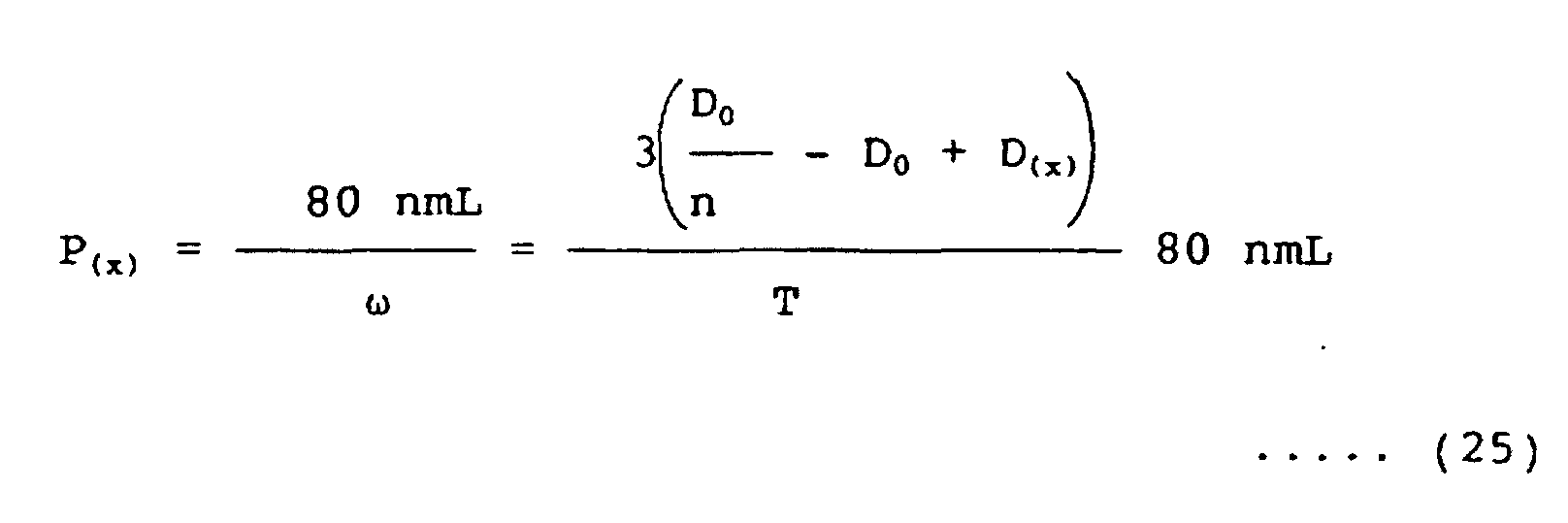
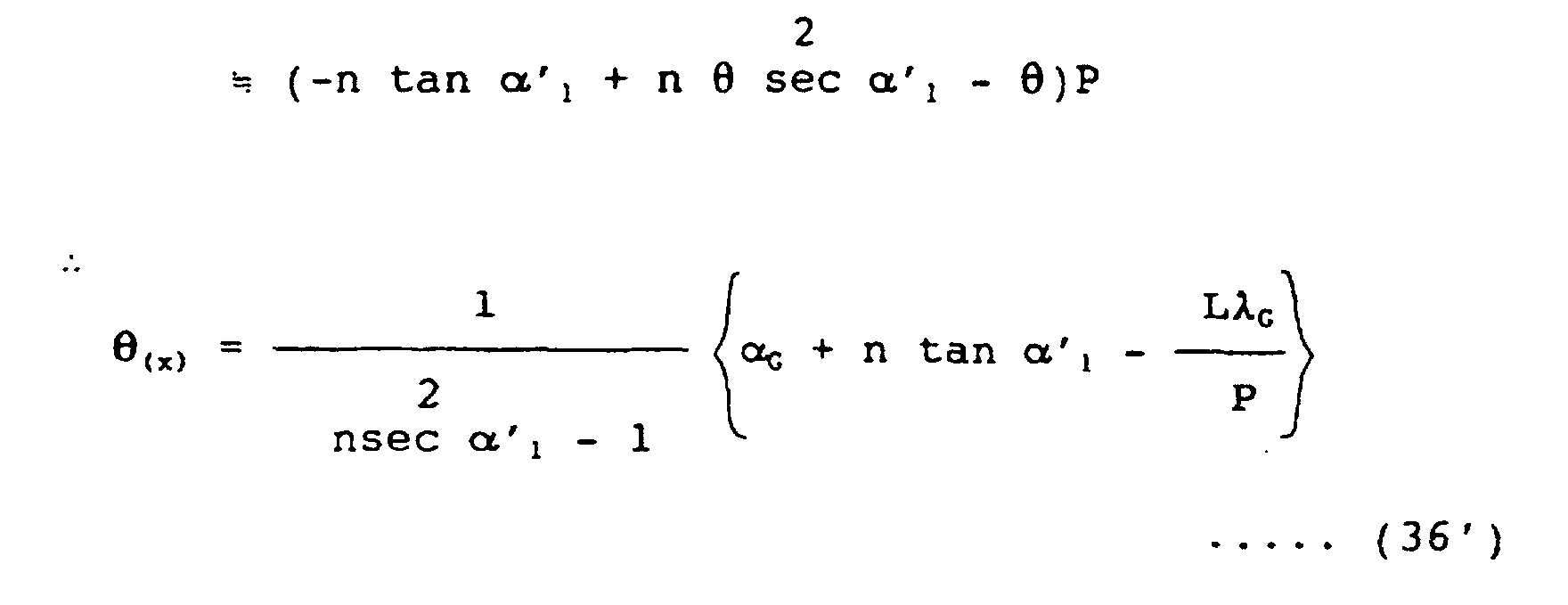
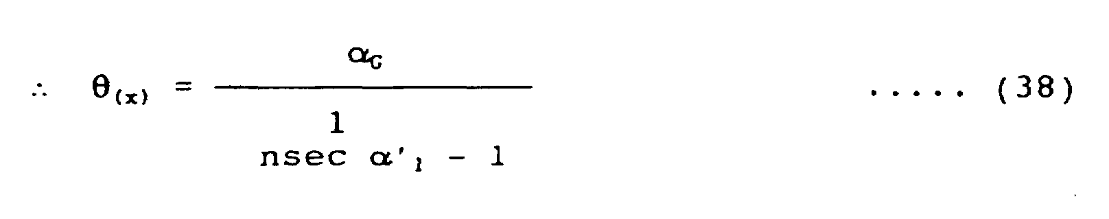
- The main difference of the equations in the eighth embodiment from those in the preceding embodiment is that LλG has a negative sign in equation (36) contrary to the positive sign that LλG had in equation (28) in the seventh embodiment. The reason for this difference is because in Fig. 14 the zero order light output is oriented in the direction of the above right of the drawing. In this structure, equation (25) regarding the R-G separation angle ω and equation (38) regarding the deflected angle of advancing G ray, αG, can be made compatible independently, so that Items 3.4 and 3.5 in Fig. 1 can be made compatible. Expression (39) is a recommended condition to be satisfied by the deflected angle α1" of the discontinuation faces of the diffraction gratings to improve the diffraction efficiency. With this, description of the eighth embodiment is finished.
- Fig. 16 shows a ninth embodiment of the present invention. In Fig. 16, the parts designated by the reference numerals are the same as have been described above. In other words, this ninth embodiment is formed by adding field lens means 4 for reducing the light diverging angle to Fig. 14, to thereby decrease the diverging angle of rays output from the panel to 3ω. The focal plane of the field lens means is arranged to substantially coincide with the position of the diffraction gratings 37'.
- A modification is possible, which is formed by adding the black stripe means 31 shown in Fig. 10 to this ninth embodiment, and this modification is included in the present invention. In Fig. 16, the collimator means 4 may be provided on the light input face 4" of the panel means. The diffraction gratings 37' may be provided on the face 37". With this, description of Fig. 16 is finished.
- Fig. 17 shows a tenth embodiment of the present invention. In Fig. 17, reference numeral 33" denotes light diffracting means having macro prisms combined with a lenticular face, 34' denotes a shape formed of macro prisms combined with a lenticular face formed on the light input face of the diffracting means, 31 denotes black stripe means, and 39 denotes diffraction grating. The operation principle of this tenth embodiment may be understood from the arrow-marked light rays and the descriptions of the drawings shown above. In Fig. 17, the focal plane of the collimator means for reducing the light diverging angle is arranged so as to substantially coincide with the position of the diffraction grating 39. The provision of the black stripe means 31 increases light loss, but there is an advantage that the diverging angle of output from the panel can be reduced to less than 3 ω.
- Fig. 18 is a graph showing the applicable range of the eighth and ninth embodiments of the present invention shown in Figs. 14 and 16.
- Fig. 18 graphically depicts equation (37) and corresponds to a case where the material has a normal refractive index value of 1.5. To limit the deflected angle of the light going through the medium, α1' to about 0.6 or less rad is required to practically realize the prism components. Therefore, the applicable range of the eighth and ninth embodiments is the range indicated by 50 in Fig. 8. This range fully covers the range shown in inequality (10) mentioned above.
- It ought to be noted that the first to sixth embodiments are used in applications which require greater R-G separation angles.
- When the collimator means included in the block 23 has chromatic aberration, by correcting the value of R-G separation angle ω according to the amount of the chromatic aberration at issue, the chromatic aberration can be compensated.
- In a direct viewing type liquid crystal display, a line light source is normally used for the light source means in the block 23. The collimator means is formed by combining a light guide plate, a row of prisms, black stripes, lenticular lenses, and so on. In such an application as this, the present invention can be applied if about 0.3 to 0.6 rad is selected for the value of the R-G separation angle ω. With this, description of the preferred embodiments of the present invention is finished.
- In the embodiments from Fig. 8 onwards, which belong to Type II of the present invention, the array pitch of macro lenticular elements is substantially equal to the array pitch of the liquid crystal panel means. Therefore, the thermal expansion coefficients of the materials need to be matched to that of the liquid crystal panel means. The liquid crystal panel means is normally made of a glass material. Accordingly, in the embodiments of the present invention, too, a glass material is ordinarily used as the material of the macro lenticular type light diffracting means. The diffraction grating and the lenticular elements provided at the surface of the macro lenticular type light diffracting means are formed of a glass or resin material, but for general applications, a ultraviolet-light-hardening type resin material is recommended.
- In the above presentation of the embodiments of the present invention, description has been made on the assumption that there is air in the spaces between the different components.
- However, those spaces may be filled with a resin material having a smaller refractive index than that of the components of the embodiment. In this case, each embodiment can be formed by taking into consideration a fact that the effective optical path difference nh1 - h2 changes to nh1 - n2h2.
- The liquid crystal display apparatus according to the present invention is not limited to the direct viewing type, but may be applied to the projection type and the optical fiber type. Fig. 19 shows an application of the present invention to the projection type display. In Fig. 19, reference numeral 40 denotes a block, typical of the embodiments described above, which includes the above-mentioned macro prism type or macro lenticular type light diffracting means in the present invention. Reference numeral 23 denotes a block including light source means and collimator means, 1 denotes liquid crystal panel means, 41 denotes projection lens means, and 42 denotes screen means.
- Fig. 20 shows an application of the present invention to the optical fiber type display. In Fig. 20, reference numeral 43 denotes optical fiber, 44 denotes a fiber light input end, and 45 denotes a fiber light output end plus fiber screen means.
- When a liquid crystal panel utilizing the polarization of light is applied, in every embodiment, the use of P wave (equivalent to Ez wave, or TM wave in the field of electric wave, is not essential but is recommended. The reason is that the interface reflection loss of P wave is, as is well known, smaller than that of S wave, which makes it possible to construct a high-efficiency optical system. With this, the introduction of the embodiments and applications of the present invention is finished.
- According to those embodiments of the present invention, there is provided a single plate type color liquid crystal display apparatus with improved light transmission efficiency, which is capable of separating the input white light into three primary colors traveling in different directions, and guiding the three color rays to the corresponding pixels of the single plate liquid crystal panel means.
- According to the first (Fig. 6) and the second (Fig. 7) embodiments of the present invention, it is possible to set the R-G separation angle by the light diffracting means at 0.05 rad or more and the deflected angle of the green ray at 0.17 rad or less, making it possible provide a compact optical system.
- According to the third to tenth embodiments of the present invention, it is possible to achieve the compatibility of the converging actions by the light diffracting means into the R, G and B pixels, with the result that a liquid crystal display apparatus can be provided which has reduced color mixture, hence high picture quality, and less required power consumption.
- To be more specific, as against the deterioration ratio of the light converging action of about 1.6 in the prior art, according to Type II in the present invention, that deterioration ratio can be reduced to about 1.4 or less, so that the utilization efficiency of R and B rays is thereby improved.
Claims (10)
- A single plate type color liquid crystal display apparatus having light source means (23), collimator means (3;26'), and single plate type liquid crystal panel means (1), comprising:wherein said light diffracting means (27) is formed, at a macroscopic level, as a three-dimensional unflat plate form with a macro periodic structural pitch and additionally has at least either a macro-prism shape (26) or a macro lenticular shape (26'), and also includes a multi-stepped diffraction grating (27) at a microscopic level, wherein the macro periodic structural pitch is larger than 53 µm, wherein white light, inputted from the light source to the diffracting means and outputted therefrom, is decomposed into three primary color rays traveling in three different directions, wherein a red-green separation angle ω between a red ray and a green ray in said three primary color rays is larger than 0.05 rad, wherein an effective unit optical path difference at a unit step of said multi-stepped diffraction grating (27) for at least the principal ray is set to an integer number L, L being an integer out of 1, 2 and 3, times the characteristic optical wavelength λ0 of the system, wherein the projection P of the pitch P0 of said unit step in the direction of said green output ray is substantially equal to L times a red-green wavelength difference divided by said red-green separation angle ω, more specifically, 80L nm/ω, and wherein said three primary color rays (R, G and B) as outputted by the diffracting means, travelling in three different directions, are converged by the three position means to specified respective three color positions of the liquid crystal panel.light diffracting means (27) arranged between said collimator means (23) and said single plate liquid crystal panel means (1); andthree-position means for directing light rays of three primary colors diffracted by said diffraction means to respective pixel positions of said liquid crystal panel,
- A single plate type color liquid crystal display apparatus according to Claim 1, wherein a difference between said specific optical wavelength is smaller than 260 nm.
- A single plate type color liquid crystal display apparatus according to Claim 1, wherein said macro-prism shape is formed on the input side of said light diffracting means (27).
- A single plate type color liquid crystal display apparatus according to Claim 1, wherein said macro-prism shape (26) is formed on the output side of said light diffracting means (27).
- A single plate type color liquid crystal display apparatus according to Claim 1, wherein said macro periodic structural pitch (Q) of said macro lenticular shape (26') is arranged substantially equal to a three-color-pixel array period T of said liquid crystal panel means, and wherein said effective unit optical path difference is modulated periodically so that each green output ray is directed to a respective green pixel (G) of said liquid crystal panel, therefore said red-green separation angle ω and the advancing direction of said green output ray are selected independently of each other, with the result that said three-position means (3) and its function of converging said three primary color rays is implemented by said light diffracting means (27).
- A single plate type color liquid crystal display apparatus according to Claim 5, wherein a divergence-reducing field lens means (4) is installed at the output face of said light diffracting means (27), wherein the focal plane of said divergence-reducing field lens means (4) is made to substantially coincide with the position of said multi-stepped diffraction grating of said light diffracting means (27), and wherein said primary color rays travelling in three different directions are directed to the respective three pixels (R, G and B) at every three-pixel pitch.
- A single plate type color liquid crystal display apparatus according to Claim 1, wherein said macro lenticular shape (26') is provided as a shape formed of macro prisms combined with a macro lenticular face, wherein black stripe means (31) and a divergence-reducing collimator means are installed at the output face of said diffraction grating, and wherein the focal plane of said divergence-reducing collimator means is made substantially equal to the position of said diffraction grating.
- A single plate type color liquid crystal display apparatus according to Claim 5, further comprising black stripe means (31), wherein said black stripe means is arranged at least either on the input face of said diffracting means (27) or on a face subsequent to said light diffracting means (27).
- A projection-version single plate type color liquid crystal display apparatus according to Claim 6, 7 or 8, further comprising projection lens means (41) and screen means (42).
- A single plate type color liquid crystal display apparatus according to Claim 6, 7 or 8, further comprising optical fiber means (43) and fiber screen means (45), wherein said optical fiber means is used to guide the output light of said single plate type liquid crystal panel means (1) to said fiber screen means (45).
Applications Claiming Priority (3)
| Application Number | Priority Date | Filing Date | Title |
|---|---|---|---|
| JP8095036A JPH09284684A (en) | 1996-04-17 | 1996-04-17 | Single ccd type color liquid crystal display device |
| JP9503696 | 1996-04-17 | ||
| JP95036/96 | 1996-04-17 |
Publications (3)
| Publication Number | Publication Date |
|---|---|
| EP0802685A2 EP0802685A2 (en) | 1997-10-22 |
| EP0802685A3 EP0802685A3 (en) | 1999-04-07 |
| EP0802685B1 true EP0802685B1 (en) | 2004-09-08 |
Family
ID=14126863
Family Applications (1)
| Application Number | Title | Priority Date | Filing Date |
|---|---|---|---|
| EP97105927A Expired - Lifetime EP0802685B1 (en) | 1996-04-17 | 1997-04-10 | Single plate liquid crystal colour display apparatus employing a diffraction grating |
Country Status (6)
| Country | Link |
|---|---|
| US (2) | US5801795A (en) |
| EP (1) | EP0802685B1 (en) |
| JP (1) | JPH09284684A (en) |
| KR (1) | KR100229515B1 (en) |
| CN (1) | CN1092898C (en) |
| DE (1) | DE69730553T2 (en) |
Families Citing this family (50)
| Publication number | Priority date | Publication date | Assignee | Title |
|---|---|---|---|---|
| JPH10115871A (en) * | 1996-10-14 | 1998-05-06 | Canon Inc | Image projector |
| EP0841821A3 (en) * | 1996-11-06 | 2000-01-12 | Canon Kabushiki Kaisha | Projection apparatus |
| US6104446A (en) * | 1996-12-18 | 2000-08-15 | Blankenbecler; Richard | Color separation optical plate for use with LCD panels |
| JP3647206B2 (en) * | 1997-05-20 | 2005-05-11 | キヤノン株式会社 | Optical modulation device and projection device using the same |
| JPH11149061A (en) * | 1997-09-12 | 1999-06-02 | Minolta Co Ltd | Light source device and illumination device |
| US6480333B1 (en) * | 1997-11-19 | 2002-11-12 | California Institute Of Technology | Diffractive optical elements on non-flat substrates using electron beam lithography |
| JP3779052B2 (en) * | 1997-12-17 | 2006-05-24 | 株式会社半導体エネルギー研究所 | LCD projector |
| US6678023B1 (en) | 1997-12-17 | 2004-01-13 | Semiconductor Energy Laboratory Co., Ltd. | Liquid crystal projector |
| JP2000075259A (en) * | 1998-06-16 | 2000-03-14 | Seiko Epson Corp | Liquid crystal device and projection type display device using the same |
| FI106323B (en) | 1998-12-30 | 2001-01-15 | Nokia Mobile Phones Ltd | Backlight light guide for flat screen |
| JP2000329925A (en) * | 1999-05-18 | 2000-11-30 | Sony Corp | Device and method for limiting angle of light divergence and projection type image display device |
| US6351334B1 (en) * | 2000-10-10 | 2002-02-26 | Industrial Technology Research Institute | Reflective diffraction grating for use in display devices |
| JP2002122809A (en) * | 2000-10-18 | 2002-04-26 | Canon Inc | Projection type display device |
| US6600528B2 (en) | 2000-12-19 | 2003-07-29 | International Business Machines Corporation | Integrated prism sheet for improved viewing angle in direct view color filterless liquid crystal displays |
| KR100482318B1 (en) * | 2001-05-23 | 2005-04-13 | 엘지전자 주식회사 | Color Scrolling Apparatus of Rear Projector |
| CN1313846C (en) * | 2001-10-05 | 2007-05-02 | 松下电器产业株式会社 | Diffraction optical element and optical head with the diffraction optical element |
| DE60330521D1 (en) * | 2002-04-04 | 2010-01-28 | Canon Kk | Diffractive optical element with a variety of diffraction gratings and optical system |
| KR20040011761A (en) | 2002-07-30 | 2004-02-11 | 삼성전자주식회사 | High resolution display comprising pixel moving means |
| JPWO2004031815A1 (en) * | 2002-10-07 | 2006-03-23 | ナルックス株式会社 | Anti-reflection diffraction grating |
| CN100426091C (en) * | 2003-05-02 | 2008-10-15 | 鸿富锦精密工业(深圳)有限公司 | Backlight module and light conducting plate |
| JP2005062692A (en) * | 2003-08-19 | 2005-03-10 | Internatl Business Mach Corp <Ibm> | Color display device, optical element, and method for manufacturing color display device |
| CN100468151C (en) * | 2004-03-11 | 2009-03-11 | 鸿富锦精密工业(深圳)有限公司 | Straight-down type back-light module group |
| US20060056028A1 (en) * | 2004-09-13 | 2006-03-16 | Wildnauer Kenneth R | Apodized diffraction grating with improved dynamic range |
| TWI255349B (en) * | 2005-02-02 | 2006-05-21 | Asia Optical Co Inc | Optical system of a projector display and a projector device equipped with this optical system |
| US7554623B2 (en) * | 2005-02-18 | 2009-06-30 | Infocus Corporation | Optical assembly to provide complementary illumination of subpixels of a light valve pixel |
| US7868847B2 (en) * | 2005-05-24 | 2011-01-11 | Mark W Miles | Immersive environments with multiple points of view |
| US7729052B2 (en) * | 2005-07-01 | 2010-06-01 | Cotton Christopher T | Non-planar optical diffraction grating having an arbitrary parallel groove profile |
| WO2007115664A1 (en) * | 2006-04-06 | 2007-10-18 | Oc Oerlikon Balzers Ag | Projection illumination system, in which lenses with diffractive optical elements are used. |
| KR101217160B1 (en) * | 2006-08-09 | 2012-12-31 | 엘지디스플레이 주식회사 | Liquid Crystal Display Device using a microprism |
| KR100993383B1 (en) * | 2007-03-15 | 2010-11-09 | 제일모직주식회사 | Diffuser prism sheet comprising light diffuser in the valley of prism and LCD back light unit thereby |
| KR101243709B1 (en) * | 2008-02-22 | 2013-03-13 | 주식회사 엘지화학 | Deflecting film with double-faced shape and side light type back light unit using the same |
| TWI354809B (en) * | 2008-06-24 | 2011-12-21 | Ind Tech Res Inst | Composite optical dividing device |
| TWI391707B (en) * | 2008-10-30 | 2013-04-01 | Ind Tech Res Inst | Composite optical dividing device |
| TWI424200B (en) * | 2008-12-31 | 2014-01-21 | Ind Tech Res Inst | Color dividing optical device and image apparatus with the application |
| CN101799589B (en) * | 2009-02-09 | 2013-05-08 | 财团法人工业技术研究院 | Color split optical element and image panel device |
| US8290318B2 (en) * | 2009-04-21 | 2012-10-16 | Svv Technology Innovations, Inc. | Light trapping optical cover |
| US20100309554A1 (en) * | 2009-06-03 | 2010-12-09 | Panasonic Corporation | Color separation microlens and color separation grating |
| GB2476799A (en) * | 2010-01-07 | 2011-07-13 | Sharp Kk | Reflective display, sensor and camera |
| US8902506B2 (en) | 2010-09-30 | 2014-12-02 | Panasonic Corporation | Laser speckle reduction element |
| US8740397B2 (en) * | 2011-01-18 | 2014-06-03 | Svv Technology Innovations, Inc. | Optical cover employing microstructured surfaces |
| US20130033752A1 (en) * | 2011-08-04 | 2013-02-07 | Chien-Yue Chen | Diffraction-type 3d display element and method for fabricating the same |
| JP2013044800A (en) * | 2011-08-22 | 2013-03-04 | Sony Corp | Illumination device and display device |
| WO2015016844A1 (en) * | 2013-07-30 | 2015-02-05 | Leia Inc. | Multibeam diffraction grating-based backlighting |
| KR20160067546A (en) * | 2014-12-04 | 2016-06-14 | 한국전자통신연구원 | Directional back light unit |
| CN106959518B (en) * | 2016-01-08 | 2020-02-18 | 京东方科技集团股份有限公司 | Display panel and display device |
| CN106094331B (en) * | 2016-06-03 | 2019-03-12 | 京东方科技集团股份有限公司 | A kind of display panel and display device |
| CN106324898B (en) * | 2016-10-28 | 2017-08-25 | 京东方科技集团股份有限公司 | Display panel and display device |
| JP7062366B2 (en) * | 2017-03-03 | 2022-05-06 | 株式会社ジャパンディスプレイ | Display device, display method and color separation element |
| CN107144904B (en) * | 2017-05-25 | 2019-06-04 | 北京理工大学 | A kind of achromatism grating, colour killing difference method and near-eye display system |
| DE102018212719A1 (en) * | 2018-07-31 | 2020-02-20 | Dr. Johannes Heidenhain Gesellschaft Mit Beschränkter Haftung | Optical position measuring device |
Family Cites Families (15)
| Publication number | Priority date | Publication date | Assignee | Title |
|---|---|---|---|---|
| JPS60146590A (en) * | 1984-01-10 | 1985-08-02 | Citizen Watch Co Ltd | Polychromatic image display device |
| JPH0792566B2 (en) * | 1986-06-12 | 1995-10-09 | キヤノン株式会社 | Color display device |
| JPS63118125A (en) * | 1986-11-06 | 1988-05-23 | Hitachi Ltd | Liquid crystal display device |
| US4798448A (en) * | 1988-02-16 | 1989-01-17 | General Electric Company | High efficiency illumination system for display devices |
| JPH0659318A (en) * | 1991-07-19 | 1994-03-04 | Canon Inc | Camera |
| WO1993011452A1 (en) * | 1991-11-25 | 1993-06-10 | Magnascreen Corporation | Microprojection display system with fiber-optic illuminator, and method of display and illumination |
| US5264880A (en) * | 1991-12-30 | 1993-11-23 | Xerox Corporation | Method and apparatus for projecting a color image |
| US5537171A (en) * | 1992-03-13 | 1996-07-16 | Hitachi, Ltd. | Liquid crystal projection display |
| GB2269697A (en) * | 1992-08-11 | 1994-02-16 | Sharp Kk | Display device |
| US5506701A (en) * | 1993-01-28 | 1996-04-09 | Dai Nippon Printing Co., Ltd. | Hologram color filter, liquid crystal display device using the same, and fabrication process of hologram color filter |
| JP2643755B2 (en) * | 1993-02-26 | 1997-08-20 | 株式会社日立製作所 | Liquid crystal display |
| FR2707447B1 (en) * | 1993-07-09 | 1995-09-01 | Thomson Csf | Color display device. |
| US5682265A (en) * | 1994-02-18 | 1997-10-28 | Massachusetts Institute Of Technology | Diffractive microstructures for color separation and fusing |
| EP0692730A3 (en) * | 1994-07-12 | 1996-03-20 | Dainippon Printing Co Ltd | Liquid crystal display apparatus and liquid crystal projection display apparatus which employ hologram color filter |
| US5781257A (en) * | 1995-01-30 | 1998-07-14 | Lockheed Martin Missiles & Space Co | Flat panel display |
-
1996
- 1996-04-17 JP JP8095036A patent/JPH09284684A/en active Pending
-
1997
- 1997-04-10 DE DE69730553T patent/DE69730553T2/en not_active Expired - Fee Related
- 1997-04-10 EP EP97105927A patent/EP0802685B1/en not_active Expired - Lifetime
- 1997-04-10 US US08/838,831 patent/US5801795A/en not_active Expired - Fee Related
- 1997-04-16 KR KR1019970013968A patent/KR100229515B1/en not_active IP Right Cessation
- 1997-04-17 CN CN97113205A patent/CN1092898C/en not_active Expired - Fee Related
-
1998
- 1998-07-22 US US09/120,324 patent/US6064452A/en not_active Expired - Fee Related
Also Published As
| Publication number | Publication date |
|---|---|
| JPH09284684A (en) | 1997-10-31 |
| KR100229515B1 (en) | 1999-11-15 |
| US6064452A (en) | 2000-05-16 |
| DE69730553T2 (en) | 2005-01-27 |
| DE69730553D1 (en) | 2004-10-14 |
| CN1175164A (en) | 1998-03-04 |
| US5801795A (en) | 1998-09-01 |
| CN1092898C (en) | 2002-10-16 |
| EP0802685A3 (en) | 1999-04-07 |
| EP0802685A2 (en) | 1997-10-22 |
Similar Documents
| Publication | Publication Date | Title |
|---|---|---|
| EP0802685B1 (en) | Single plate liquid crystal colour display apparatus employing a diffraction grating | |
| US6343862B1 (en) | Projecting image display device | |
| CA2065584C (en) | Plate-like polarizing element, a polarizing conversion unit provided with the element, and a projector provided with the unit | |
| US6535256B1 (en) | Color liquid crystal display device | |
| US4687301A (en) | Full-color projector system with a tricolor-separating prism | |
| EP1031870B1 (en) | Illumination system and projector | |
| KR100359594B1 (en) | Optical projection apparatus, transmission type screen, and projection type image display apparatus | |
| EP0717865B1 (en) | Liquid crystal projection display systems | |
| US20190018248A1 (en) | Optical apparatus | |
| US8421956B2 (en) | Composite color separation system | |
| US8305527B2 (en) | Color separation system | |
| JPH03140920A (en) | Projection type display device and liquid crystal display device used for this projection type display device | |
| JPH11271677A (en) | Color projection display device | |
| EP1780560B1 (en) | Spatial light modulator and projector | |
| US6793344B2 (en) | Optical systems for liquid crystal display projectors | |
| US6481852B2 (en) | Projector apparatus comprising a light composing optical system vertically stacked with respect to a light separation optical system | |
| JP4579384B2 (en) | Color synthesizing optical system and projection display apparatus having the color synthesizing optical system | |
| US7267443B2 (en) | Light-modulating projector | |
| US6141124A (en) | Color filter and color picture display device using the same | |
| US5184234A (en) | Stacked LCD color projector with equal path lengths | |
| US6398365B1 (en) | Image projection display apparatus | |
| KR20050025904A (en) | Image projection apparatus | |
| EP0746163A1 (en) | Projection type color image display device | |
| JP3744233B2 (en) | Polarization separator and projection-type image display device | |
| JPH09329788A (en) | Hologram color filter system |
Legal Events
| Date | Code | Title | Description |
|---|---|---|---|
| PUAI | Public reference made under article 153(3) epc to a published international application that has entered the european phase |
Free format text: ORIGINAL CODE: 0009012 |
|
| 17P | Request for examination filed |
Effective date: 19970410 |
|
| AK | Designated contracting states |
Kind code of ref document: A2 Designated state(s): DE FR GB |
|
| PUAL | Search report despatched |
Free format text: ORIGINAL CODE: 0009013 |
|
| AK | Designated contracting states |
Kind code of ref document: A3 Designated state(s): DE FR GB |
|
| GRAP | Despatch of communication of intention to grant a patent |
Free format text: ORIGINAL CODE: EPIDOSNIGR1 |
|
| RTI1 | Title (correction) |
Free format text: SINGLE PLATE LIQUID CRYSTAL COLOUR DISPLAY APPARATUS EMPLOYING A DIFFRACTION GRATING |
|
| GRAS | Grant fee paid |
Free format text: ORIGINAL CODE: EPIDOSNIGR3 |
|
| GRAA | (expected) grant |
Free format text: ORIGINAL CODE: 0009210 |
|
| AK | Designated contracting states |
Kind code of ref document: B1 Designated state(s): DE FR GB |
|
| REG | Reference to a national code |
Ref country code: GB Ref legal event code: FG4D |
|
| REF | Corresponds to: |
Ref document number: 69730553 Country of ref document: DE Date of ref document: 20041014 Kind code of ref document: P |
|
| PGFP | Annual fee paid to national office [announced via postgrant information from national office to epo] |
Ref country code: FR Payment date: 20050218 Year of fee payment: 9 |
|
| PG25 | Lapsed in a contracting state [announced via postgrant information from national office to epo] |
Ref country code: GB Free format text: LAPSE BECAUSE OF NON-PAYMENT OF DUE FEES Effective date: 20050410 |
|
| PGFP | Annual fee paid to national office [announced via postgrant information from national office to epo] |
Ref country code: DE Payment date: 20050421 Year of fee payment: 9 |
|
| PLBE | No opposition filed within time limit |
Free format text: ORIGINAL CODE: 0009261 |
|
| STAA | Information on the status of an ep patent application or granted ep patent |
Free format text: STATUS: NO OPPOSITION FILED WITHIN TIME LIMIT |
|
| ET | Fr: translation filed | ||
| 26N | No opposition filed |
Effective date: 20050609 |
|
| GBPC | Gb: european patent ceased through non-payment of renewal fee |
Effective date: 20050410 |
|
| PG25 | Lapsed in a contracting state [announced via postgrant information from national office to epo] |
Ref country code: DE Free format text: LAPSE BECAUSE OF NON-PAYMENT OF DUE FEES Effective date: 20061101 |
|
| REG | Reference to a national code |
Ref country code: FR Ref legal event code: ST Effective date: 20061230 |
|
| PG25 | Lapsed in a contracting state [announced via postgrant information from national office to epo] |
Ref country code: FR Free format text: LAPSE BECAUSE OF NON-PAYMENT OF DUE FEES Effective date: 20060502 |