EP0801464A1 - Current shaping in reluctance machines - Google Patents
Current shaping in reluctance machines Download PDFInfo
- Publication number
- EP0801464A1 EP0801464A1 EP97302229A EP97302229A EP0801464A1 EP 0801464 A1 EP0801464 A1 EP 0801464A1 EP 97302229 A EP97302229 A EP 97302229A EP 97302229 A EP97302229 A EP 97302229A EP 0801464 A1 EP0801464 A1 EP 0801464A1
- Authority
- EP
- European Patent Office
- Prior art keywords
- current
- period
- signal
- circuit
- counter
- Prior art date
- Legal status (The legal status is an assumption and is not a legal conclusion. Google has not performed a legal analysis and makes no representation as to the accuracy of the status listed.)
- Granted
Links
Images


Classifications
-
- H—ELECTRICITY
- H02—GENERATION; CONVERSION OR DISTRIBUTION OF ELECTRIC POWER
- H02P—CONTROL OR REGULATION OF ELECTRIC MOTORS, ELECTRIC GENERATORS OR DYNAMO-ELECTRIC CONVERTERS; CONTROLLING TRANSFORMERS, REACTORS OR CHOKE COILS
- H02P25/00—Arrangements or methods for the control of AC motors characterised by the kind of AC motor or by structural details
- H02P25/02—Arrangements or methods for the control of AC motors characterised by the kind of AC motor or by structural details characterised by the kind of motor
- H02P25/08—Reluctance motors
- H02P25/092—Converters specially adapted for controlling reluctance motors
- H02P25/0925—Converters specially adapted for controlling reluctance motors wherein the converter comprises only one switch per phase
Definitions
- This invention relates to current shaping in reluctance machines.
- the present invention relates to a current control circuit for reducing vibrations in a switched reluctance machine.
- a reluctance machine is an electric machine in which torque is produced by the tendency of its movable part to move into a position where the inductance of an excited winding is maximized.
- the general theory, design and operation of switched reluctance machines is well known and is discussed, for example, in the paper "The Characteristics, Design and Applications of Switched Reluctance Motors and Drives" by Stephenson and Blake and presented at the PCIM '93 Conference and Exhibition at distress, Germany, June 21-24, 1993.
- Figure 1 illustrates a typical switched reluctance machine having a stator 10 including six projecting stator poles 11-16 that define a principal stator axis (extending outwardly from Figure 1).
- a rotor 18 is coupled to a rotatable shaft co-axial with the principal axis of the stator.
- the rotor is positioned within the bore formed by the stator and the inwardly pointing stator poles 11-16 and is mounted on a shaft (not shown) that is mounted on bearings and is free to rotate.
- the rotor 18 has a number of outwardly extending projections 19 which form the rotor poles.
- phase A coils from poles 11 and 14
- phase B coils from poles 12 and 15
- phase C coils from poles 13 and 16
- phase A when phase A is energised, current will flow through its coils such that stator pole 11 becomes, for example, an inward-pointing electromagnet of positive polarity and stator pole 14 becomes an inward-pointing electromagnet of negative polarity.
- phase A when phase A is energised, current will flow through its coils such that stator pole 11 becomes, for example, an inward-pointing electromagnet of positive polarity and stator pole 14 becomes an inward-pointing electromagnet of negative polarity.
- the desired torque may be maintained regardless of the angular position of the rotor.
- the machine By switching the energisation of the phase windings to develop positive torque, the machine may be operated as a motor; by energisation of the phase windings to develop a retarding torque the machine may be operated as a brake or generator.
- a simple form of machine having six stator poles and two rotor poles i.e. a 6/2 machine
- Those skilled in the art will recognize that other combinations are well-known.
- the present invention applies equally to such machines.
- the present invention is applicable to inverted machines, where the stator is positioned within the bore of an outer rotating rotor, and to linear machines, in which the movable member moves linearly with respect to the stator.
- the movable member of a linear motor is also commonly referred to as a rotor.
- the torque may be adjusted by monitoring the rotor's position, energising one or more phase windings when the rotor is at a first angular position, referred to as the "turn-on angle", and then de-energising the energised windings when the rotor rotates to a second angular position, referred to as the "turn-off angle".
- the angular distance between the turn-on angle and the turn-off angle is known as the “conduction angle", constituting the limits of an active period in which the phase winding is energised.
- the torque of a switched reluctance machine can be controlled by varying the current in the energised phases over the period defined by the turn-on and turn-off angles.
- Such current control can be achieved by chopping the current using a current reference with phase current feedback.
- Such current control is referred to as "chopping mode” current control.
- PWM pulse width modulation
- Chopping mode current control and PWM control strategies are generally understood and chopping mode current control is generally described below.
- Figure 2A illustrates an exemplary current in a phase winding when chopping mode current control is used when the switched reluctance machine is operating as a motor.
- the phase is initially energised at a point corresponding to the turn-on angle and current begins to increase until it reaches the current reference.
- the current is chopped by a controller, de-energising the phase winding.
- the current drops until the phase winding is again re-energised and the process repeats.
- the overall shape of the current waveform defines a substantially rectangular region where the beginning and end points of the rectangular region generally correspond to the turn-on and turn-off angles, defining between them the conduction angle.
- Figure 3 generally illustrates power circuitry that may be used to control the energisation of a phase winding for both chopping mode and single-pulse mode current control.
- a phase winding 30 is coupled to a source of DC power provided through a DC bus, comprising positive and negative rails 31/32, by upper switching device 33 and lower switching device 34.
- Return diodes 35 and 36 provide a current path from the DC bus through the phase winding 30 when switching devices 33 and 34 are opened.
- phase winding 30 is generally energised by closing switches 33 and 34, thus coupling the phase winding to the DC bus.
- the circuit illustrated in Figure 3 may be used to implement chopping mode current control as follows: when the rotor reaches an angular position that corresponds to the turn-on angle, switches 33 and 34 are closed. The phase winding 30 is then coupled to the DC bus, causing an increasing magnetic flux to be established in the motor. It is the magnetic field associated with this flux which acts on the rotor poles to produce the motor torque. As the magnetic flux in the machine increases, current flows from the DC supply as provided by the DC bus, through the switches 33 and 34 and through the phase winding 30.
- the current flowing through the phase winding 30 is sensed by a current sensor or other device (not shown) that provides a signal corresponding to the magnitude of the phase current.
- the signal corresponding to the phase current is then compared with a signal representing a reference current.
- the phase winding is de-energised by opening one or both of switches 33 and 34.
- both switches 33 and 34 are opened, the current in the phase winding 30 transfers from switches 33 and 34 and flows through the diodes 35 and 36.
- the diodes 35 and 36 then apply the DC voltage appearing on the DC bus in the opposite sense, causing the magnetic flux in the machine (and therefore the phase current) to decrease.
- the phase is re-energised and the current again begins to increase.
- switches 33 and 34 are opened, and the phase current is allowed to drop to zero.
- the diodes 35 and 36 turn off, disconnecting the phase winding from the power supply.
- unwanted vibration and acoustic noise may also be produced by abrupt changes in the magnetic forces in the motor.
- the abrupt application or removal of magnetic force can cause the stator to vibrate at one or more of its natural resonance frequencies.
- the lowest (or fundamental) natural frequency dominates the vibration, although higher harmonics can be emphasized by repeated excitation at the appropriate frequency.
- stator distortions resulting from the ovalising and vibration phenomena described above the fluctuating magnetic forces in the motor can distort the stator in other ways, as well as distorting the rotor and other ferromagnetic parts of the machine. These additional distortions are another potential source of unwanted vibration and noise.
- This approach is typically implemented by switching off one of the power devices at a first point in time to cause a first stepped reduction in applied voltage, and then later switching off the second power device. Between the time when the first switching device is switched off and the second switching device is switched off, the current is allowed to freewheel through a freewheeling diode and the second switching device.
- the two-step voltage-reduction approach to noise reduction in switched reluctance motors discussed above suffers from several limitations and disadvantages.
- the two-step voltage-reduction approach limits the flexibility to dynamically adjust the freewheeling period for each phase cycle.
- the duration of the freewheeling period is selected to reduce the noise produced by the system. There are many instances when it would be desirable to optimize the freewheeling duration according to other criteria.
- US-A-5461295 discloses apparatus for controlling the current profile in a switched reluctance motor.
- the phase winding current is initially at a first level in a first part of the active period of the switch cycle. Thereafter, it is linearly reduced over a second part of the active period.
- the transition between the linearly reducing current in the second part of the active period and the ramp of the decay of the current is less abrupt, producing a smoother transition.
- the present invention overcomes many of the limitations and disadvantages associated with known systems and provides a circuit for energising the winding phases of a switched reluctance machine in a particular manner to reduce unwanted noise and vibrations produced by the machine.
- the invention provides a current control circuit for a switched reluctance machine system having a phase conduction cycle for the or each phase winding of the machine, the cycle comprising an active period in which an energising voltage is applied across the phase winding to maintain a phase current, a ramp period in which the current is reduced to zero and an inactive period in which the phase winding is not energised, the circuit comprising control means for controlling the current in the phase winding, a modulator responsive to a current level signal from the control means to produce a modulated output signal, current shaping means for varying the modulation of the output signal, the control means being operable to determine the end of the active period and to enable the current shaping means to vary the modulation of the output signal in a corner period, following the active period, such that the current in the winding is reduced according to a curve determined by the control means before the ramp period.
- the invention provides a so-called corner window in which the current in a phase winding is controlled to effect a smooth transition between the active period and the current decay in the inactive period.
- the level of current in the active period, the rate of decay in the inactive period, as well as the speed of and load on the machine can all contribute to the determination of a suitable current curve in the corner window.
- the current is typically regulated to a desired level in an active period of the overall cycle of operation, as previously shown in Fig.2A.
- the switches are non-conducting.
- Each phase is controlled in sequence in the same way in accordance with the input demand and the load on the motor.
- any current in the -phase winding decays over a finite period.
- the invention provides a new way of addressing the transition from the active period in which the switches are conducting, to the period when the switches are non-conducting.
- the circuit of the invention shapes the current near the end of the active period in a so-called 'corner window' and further controls the decay of the current in a 'ramp' period as the current is taken towards zero. As part of the transition, it is necessary to determine the magnitude of the current near the end of the active period and the rate of decay of the current in the ramp period in order for it to be smooth. The effective magnitude of the current and the slope of the ramp are merged smoothly by the invention to avoid an abrupt transition between them that would otherwise provide a source of potential vibration and acoustic noise.
- a drive system for a switched reluctance motor comprises a microprocessor-based controller 100 that receives an input demand signal on line 102 that is related to a desired speed or torque output of the motor.
- a rotor position signal is fed back from a rotor position transducer 104 that is mounted to rotate with a switched reluctance motor 106 to be controlled.
- a pulse-width modulated signal on a bus 108, from a pulse width modulator 110 is adjusted in its duty cycle for the timed phase energisation of the stator windings of the motor 106.
- the output of the pulse width modulator 110 is supplied as a digital word on the bus 108, having a magnitude corresponding to the duty cycle, to a down counter and comparator 112.
- a down counter and comparator 112. In periods when the pulse width modulation is active for a given phase to control the current level during phase energisation, an active signal is transmitted on line 114 from the controller 100 to the counter and comparator 112 to disable its operation, so that the output of the counter and comparator is an unmodified form of the pulse width modulated output signal in the active period of a cycle.
- the controller 100 also generates an output that is a signal indicative of the end of the corner window on a bus 116, i.e. the moment when the corner shaping ends and the ramp down of current is begun.
- the digital word has a magnitude that is compared with the magnitude of the pulse width word on bus 120 from the down counter 112 in the corner window.
- parity between the two digital words on buses 116 and 120 will cause an output from the comparator 118 indicative of the end of the corner window period.
- the active signal from the controller 100 is also received by the comparator 118 to disable it in the active period in which energisation of the phase windings is taking place.
- the comparator thus defines the corner window in which the transition between the active period and the ramp period is to be smoothly effected.
- the other parameter of current shaping for a smooth transition between the active and inactive periods is the count rate of the counter 112.
- a multiplexer 122 is toggled from transmitting active pulses in accordance with control in the active period to current shaping pulse width modulation in the corner window by the output of the comparator 118.
- the firing signals from both the active and corner window periods are supplied to protection logic 124 which relays the output of the multiplexer 122 as a firing signal for a conventional switching circuit 126 for the machine.
- the protection logic includes a comparator which compares a signal representative of winding current with a threshold level. If the threshold is exceeded, an excess current situation exists and the switching of the motor is shut down to prevent damage to the system.
- the protection logic also produces a firing pulse trailing edge signal on line 128 which is used to synchronise the output of the down counter such that the variable pulse width modulation signal in the corner window runs on smoothly from the pulse width modulation in the active period.
- ASIC application specific integrated circuit
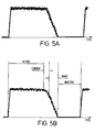
- Figure 5(a) shows the typical prior art abrupt transition in current between the active period, in which the chopped current is regulated to a desired level in the phase winding, and the ramp period.
- Figure 5(b) shows the smooth transition effected according to the invention in which a rounded current transition is made between the active period and the generally linear ramp of the decaying current.
- the rounded current shaping is effected by the down counter decrementing the duty cycle of the pulse width modulation in the corner window at a rate and over a period calculated or retrieved by the controller.
- the down counter 112 takes in the pulse width modulation signal as the eight-bit word on bus 108 and latches the value on every falling edge of the output firing pulses whilst in the active period. This is to ensure that at the end of the active period the latest pulse width modulation signal value is loaded into the counter, ready to start being decremented to produce progressively shorter pulses and so reduce the motor current to form the rounded corner.
- the count rate is effected by setting the required frequency in the controller and transmitting it as a countdown rate signal on bus 125 to the down counter 112.
- the comparator 118 compares the decremented pulse width with the end pulse width which is also sent as a calculated value from the microprocessor on bus 116. This produces the corner window period in which the countdown rate is decremented. The window starts at the end of the active period and stops when the decremented pulse width is equal to the end pulse width.
- the firing pulses continue but are made progressively shorter according to the shortening duty cycle of the pulse width modulated signal, thus lowering the current in the winding. This is done in such a way as to create a smooth transition of current from the approximately flat-topped waveform in the active period to the linear decay in the ramp period. Because the height of the flat topped current and the optimal gradient of the ramp will be likely to vary throughout the speed and torque ranges of a given motor, the controller should have sufficient control over both the period of the window and the rate at which the pulse width is decremented within the window.
- the corner window is started at a falling edge of a firing pulse in the active period, timed by the firing pulse trailing edge on line 128.
- the values of the length of the corner window and the rate at which the down count is made can be determined empirically. That is to say that at each of a set of motor load points the current wave shape is observed on an oscilloscope using, say, a Hall-effect current probe on the winding and the acoustic noise is either measured in an anechoic chamber or appraised qualitively by ear. It is then possible to compile a look-up table in the controller to hold these values. In, for example, a washing machine drive, the design may only require noise reduction at a few set speeds for different loads. Therefore, the amount of variable data can be limited to the set speeds at the load settings and then fixed in the ASIC.
- the count rate and the end count is adjusted until subjectively good noise reduction is achieved.
- the invention has been described in relation to pulse width modulation for chopping control of the phase windings.
- Other digital modulation schemes could be used relying on a digital modulation information, e.g. pulse amplitude modulation.
- an analogue implementation of the invention could derive equal benefit from the use of a corner window between the active and inactive periods of a phase conduction cycle, similarly computing a best fit curve to smooth the transition between the periods.
Abstract
Description
- This invention relates to current shaping in reluctance machines. In particular, the present invention relates to a current control circuit for reducing vibrations in a switched reluctance machine.
- In general, a reluctance machine is an electric machine in which torque is produced by the tendency of its movable part to move into a position where the inductance of an excited winding is maximized. The general theory, design and operation of switched reluctance machines is well known and is discussed, for example, in the paper "The Characteristics, Design and Applications of Switched Reluctance Motors and Drives" by Stephenson and Blake and presented at the PCIM '93 Conference and Exhibition at Nürnberg, Germany, June 21-24, 1993.
- Figure 1 illustrates a typical switched reluctance machine having a
stator 10 including six projecting stator poles 11-16 that define a principal stator axis (extending outwardly from Figure 1). Arotor 18 is coupled to a rotatable shaft co-axial with the principal axis of the stator. In Figure 1, the rotor is positioned within the bore formed by the stator and the inwardly pointing stator poles 11-16 and is mounted on a shaft (not shown) that is mounted on bearings and is free to rotate. Therotor 18 has a number of outwardly extendingprojections 19 which form the rotor poles. - Associated with each stator pole is a wound coil of wire. In the illustrated machine, the two coils of opposing stator poles are coupled together to form three phases: phase A (coils from poles 11 and 14); phase B (coils from
poles 12 and 15); and phase C (coils frompoles 13 and 16). In the example illustrated in Figure 1, when phase A is energised, current will flow through its coils such that stator pole 11 becomes, for example, an inward-pointing electromagnet of positive polarity andstator pole 14 becomes an inward-pointing electromagnet of negative polarity. These electromagnets will produce a force of attraction between the energised stator poles and the rotor poles which will produce a torque. By switching energisation from one phase to another, the desired torque may be maintained regardless of the angular position of the rotor. By switching the energisation of the phase windings to develop positive torque, the machine may be operated as a motor; by energisation of the phase windings to develop a retarding torque the machine may be operated as a brake or generator. - For the sake of illustration, a simple form of machine having six stator poles and two rotor poles (i.e. a 6/2 machine) is shown. Those skilled in the art will recognize that other combinations are well-known. The present invention applies equally to such machines. Moreover, the present invention is applicable to inverted machines, where the stator is positioned within the bore of an outer rotating rotor, and to linear machines, in which the movable member moves linearly with respect to the stator. In the art the movable member of a linear motor is also commonly referred to as a rotor.
- When a switched reluctance machine is running, the torque (and other machine performance parameters) may be adjusted by monitoring the rotor's position, energising one or more phase windings when the rotor is at a first angular position, referred to as the "turn-on angle", and then de-energising the energised windings when the rotor rotates to a second angular position, referred to as the "turn-off angle". The angular distance between the turn-on angle and the turn-off angle is known as the "conduction angle", constituting the limits of an active period in which the phase winding is energised.
- At standstill and at low speeds, the torque of a switched reluctance machine can be controlled by varying the current in the energised phases over the period defined by the turn-on and turn-off angles. Such current control can be achieved by chopping the current using a current reference with phase current feedback. Such current control is referred to as "chopping mode" current control. Alternatively, pulse width modulation (PWM) voltage control may be used. Chopping mode current control and PWM control strategies are generally understood and chopping mode current control is generally described below.
- Figure 2A illustrates an exemplary current in a phase winding when chopping mode current control is used when the switched reluctance machine is operating as a motor. As is illustrated in Figure 2A, the phase is initially energised at a point corresponding to the turn-on angle and current begins to increase until it reaches the current reference. At that point, the current is chopped by a controller, de-energising the phase winding. The current drops until the phase winding is again re-energised and the process repeats. As indicated in Figure 2A, in the chopping mode, the overall shape of the current waveform defines a substantially rectangular region where the beginning and end points of the rectangular region generally correspond to the turn-on and turn-off angles, defining between them the conduction angle.
- As the angular speed of the motor increases, a point is reached where there is insufficient time for more than a single pulse of current to occur during each phase period. Accordingly, at these speeds pulse width modulation or chopping strategies are ineffective. The torque of the motor is then commonly controlled by controlling the position and duration of the voltage pulse applied to the winding during the phase period. Because the single pulse of voltage is applied during each phase period, this form of control is referred to as "single-pulse control". This is illustrated in Figure 2B.
- Figure 3 generally illustrates power circuitry that may be used to control the energisation of a phase winding for both chopping mode and single-pulse mode current control. A phase winding 30 is coupled to a source of DC power provided through a DC bus, comprising positive and
negative rails 31/32, byupper switching device 33 andlower switching device 34.Return diodes devices closing switches - The circuit illustrated in Figure 3 may be used to implement chopping mode current control as follows: when the rotor reaches an angular position that corresponds to the turn-on angle,
switches switches - The current flowing through the phase winding 30 is sensed by a current sensor or other device (not shown) that provides a signal corresponding to the magnitude of the phase current. The signal corresponding to the phase current is then compared with a signal representing a reference current. When the actual current in the phase winding exceeds the reference current, the phase winding is de-energised by opening one or both of
switches switches switches diodes diodes - The process of energising the phase winding 30, de-energising it when the phase current exceeds the reference current, and re-energising it when the phase current drops below the reference current by a predetermined value, repeats itself during the interval defined by the turn-on and turn-off angles. Typically, when the rotor reaches an angular position corresponding to the turn-off angle,
switches diodes - As those skilled in the art will appreciate, the above discussion of current control is but one example of a
current control 1 strategy that may be used and that alternative strategies, e.g., strategies including freewheeling, may also be used. The circuit illustrated in Figure 3 may be also used to implement single-pulse mode current control. - The inherently inductive nature of a phase winding can lead to problems with transient voltage in the forms of spikes when switching a voltage across the winding. These spikes have a much larger peak magnitude than the switched voltage and a very high rate of increase and decrease. The magnitude of the voltage can damage the switch element. To counter this it is known to use a so-called 'snubber' circuit connected across the switch to suppress the transient voltage spikes in the switch. In known snubber circuits the rate of increase and decrease in the voltage transient is typically suppressed without effecting appreciably the responsiveness of the switch to apply the new voltage level to the phase winding at the desired time.
- As the above discussion indicates, as a switched reluctance motor (or generator) operates, magnetic flux is continuously increasing and decreasing in different parts of the machine. This changing flux will occur in both chopping mode and single-pulse current control. The changing flux results in fluctuating magnetic forces being applied to the ferromagnetic parts of the machine. These forces can produce unwanted vibration and noise. One major mechanism by which these forces can create noise is the ovalising of the stator caused by forces across the air-gap. Generally, as the magnetic flux increases along a given diameter of the stator, the stator is pulled into an oval shape by the magnetic forces. As the magnetic flux decreases, the stator springs back to its undistorted shape. This ovalising and springing back of the stator can cause unwanted vibration and audible noise.
- In addition to the distortions of the stator by the ovalising magnetic forces, unwanted vibration and acoustic noise may also be produced by abrupt changes in the magnetic forces in the motor. The abrupt application or removal of magnetic force can cause the stator to vibrate at one or more of its natural resonance frequencies. In general, the lowest (or fundamental) natural frequency dominates the vibration, although higher harmonics can be emphasized by repeated excitation at the appropriate frequency.
- In addition to the stator distortions resulting from the ovalising and vibration phenomena described above, the fluctuating magnetic forces in the motor can distort the stator in other ways, as well as distorting the rotor and other ferromagnetic parts of the machine. These additional distortions are another potential source of unwanted vibration and noise.
- Although the problem of unwanted acoustic noise and vibration has been recognized, known control systems for reluctance motors do not adequately solve the problem.
- For example, the general problem of acoustic noise in switched reluctance motor systems is discussed by C.Y. Wu and C. Pollock in "Analysis and Reduction of Vibration and Acoustic Noise in the Switched Reluctance Drive", Proceedings of the Industry Applications Society, IAS '93 Conference, Toronto, 2-8 Oct. 1993, pp. 106-113. In general, the method suggested by Wu and Pollock involves control of the current in the phase winding such that the current is controlled in two successive switching steps with the second switching step occurring approximately one-half of a resonance cycle after the first where the resonance cycle is defined by the natural frequency of the machine. This approach is typically implemented by switching off one of the power devices at a first point in time to cause a first stepped reduction in applied voltage, and then later switching off the second power device. Between the time when the first switching device is switched off and the second switching device is switched off, the current is allowed to freewheel through a freewheeling diode and the second switching device.
- The two-step voltage-reduction approach to noise reduction in switched reluctance motors discussed above suffers from several limitations and disadvantages. The two-step voltage-reduction approach limits the flexibility to dynamically adjust the freewheeling period for each phase cycle. As discussed above, in the two-step voltage-reduction approach, the duration of the freewheeling period is selected to reduce the noise produced by the system. There are many instances when it would be desirable to optimize the freewheeling duration according to other criteria.
- An additional limitation of the two-step voltage-reduction approach, and other approaches that utilize freewheeling to reduce noise, is that, since there is typically only one freewheeling period per phase energisation cycle, freewheeling generally reduces noise produced by only a single frequency of the motor system. Freewheeling to reduce noise at one frequency does not necessarily reduce noise produced by other frequencies in motor systems that have more than one resonance frequency. Accordingly, such approaches do not reduce many of the frequencies at which unwanted noise is produced. A further disadvantage with the freewheeling approach is that there are several motor switching circuits that simply do not allow freewheeling. These systems cannot use freewheeling to reduce noise.
- US-A-5461295 (Horst) discloses apparatus for controlling the current profile in a switched reluctance motor. The phase winding current is initially at a first level in a first part of the active period of the switch cycle. Thereafter, it is linearly reduced over a second part of the active period. When the current is to decay due to switching off the switches at the end of the active period, the transition between the linearly reducing current in the second part of the active period and the ramp of the decay of the current is less abrupt, producing a smoother transition.
- The present invention overcomes many of the limitations and disadvantages associated with known systems and provides a circuit for energising the winding phases of a switched reluctance machine in a particular manner to reduce unwanted noise and vibrations produced by the machine.
- The present invention is defined in the accompanying independent claims. Preferred features are recited in the dependent claims.
- In one particular form the invention provides a current control circuit for a switched reluctance machine system having a phase conduction cycle for the or each phase winding of the machine, the cycle comprising an active period in which an energising voltage is applied across the phase winding to maintain a phase current, a ramp period in which the current is reduced to zero and an inactive period in which the phase winding is not energised, the circuit comprising control means for controlling the current in the phase winding, a modulator responsive to a current level signal from the control means to produce a modulated output signal, current shaping means for varying the modulation of the output signal, the control means being operable to determine the end of the active period and to enable the current shaping means to vary the modulation of the output signal in a corner period, following the active period, such that the current in the winding is reduced according to a curve determined by the control means before the ramp period.
- The invention provides a so-called corner window in which the current in a phase winding is controlled to effect a smooth transition between the active period and the current decay in the inactive period. The level of current in the active period, the rate of decay in the inactive period, as well as the speed of and load on the machine can all contribute to the determination of a suitable current curve in the corner window.
- The present invention can be put into practice in various ways, some of which will now be described by way of example with reference to the accompanying drawings in which:
- Figure 1 illustrates a prior art reluctance machine;
- Figures 2A and 2B illustrate chopping mode control and single pulse control of a switched reluctance machine, respectively;
- Figure 3 illustrates a switching circuit for controlling the energisation of a phase winding of a switched reluctance machine;
- Figure 4 is a schematic diagram of an embodiment of the invention;
- Figure 5 illustrates winding current waveforms; and
- Figure 6 illustrates a winding current waveform according to the invention.
- In the chopping mode of a switched reluctance motor, the current is typically regulated to a desired level in an active period of the overall cycle of operation, as previously shown in Fig.2A. In the remaining part of the phase period, the switches are non-conducting. Each phase is controlled in sequence in the same way in accordance with the input demand and the load on the motor. When the switches are non-conducting, any current in the -phase winding decays over a finite period. The invention provides a new way of addressing the transition from the active period in which the switches are conducting, to the period when the switches are non-conducting. The circuit of the invention shapes the current near the end of the active period in a so-called 'corner window' and further controls the decay of the current in a 'ramp' period as the current is taken towards zero. As part of the transition, it is necessary to determine the magnitude of the current near the end of the active period and the rate of decay of the current in the ramp period in order for it to be smooth. The effective magnitude of the current and the slope of the ramp are merged smoothly by the invention to avoid an abrupt transition between them that would otherwise provide a source of potential vibration and acoustic noise.
- There are many known methods of current regulation which can be used to control the current during the active period. These methods include hysteresis control (where the current is allowed to fall from an upper bound to-a lower bound) and pulse width modulated (PWM) control (where the duty cycle of the PWM signal is a measure of the required current). This invention is not dependent upon any particular type of current regulation. For convenience, the description below is based on a PWM controller. Thus, the active period of a conduction cycle for a given phase corresponds to a PWM signal having a duty cycle consistent with the current level to be maintained.
- Referring to Figure 4, a drive system for a switched reluctance motor comprises a microprocessor-based
controller 100 that receives an input demand signal online 102 that is related to a desired speed or torque output of the motor. - The current waveform of the phase winding, when controlled in the manner to be described, is shown in Fig.5(b). The sections of the waveform denoted by "active", "corner", "ramp" and "inactive" are discussed below. A rotor position signal is fed back from a
rotor position transducer 104 that is mounted to rotate with a switchedreluctance motor 106 to be controlled. According to the error e, being the difference between the demand input and the actual output from the motor for a given load as derived from the output of therotor position transducer 104, a pulse-width modulated signal on abus 108, from apulse width modulator 110, is adjusted in its duty cycle for the timed phase energisation of the stator windings of themotor 106. - The output of the
pulse width modulator 110 is supplied as a digital word on thebus 108, having a magnitude corresponding to the duty cycle, to a down counter andcomparator 112. In periods when the pulse width modulation is active for a given phase to control the current level during phase energisation, an active signal is transmitted online 114 from thecontroller 100 to the counter andcomparator 112 to disable its operation, so that the output of the counter and comparator is an unmodified form of the pulse width modulated output signal in the active period of a cycle. Thecontroller 100 also generates an output that is a signal indicative of the end of the corner window on abus 116, i.e. the moment when the corner shaping ends and the ramp down of current is begun. This is a digital word supplied to a comparator andsynchronisation circuit 118. The digital word has a magnitude that is compared with the magnitude of the pulse width word onbus 120 from thedown counter 112 in the corner window. Thus, parity between the two digital words onbuses comparator 118 indicative of the end of the corner window period. - The active signal from the
controller 100 is also received by thecomparator 118 to disable it in the active period in which energisation of the phase windings is taking place. The comparator thus defines the corner window in which the transition between the active period and the ramp period is to be smoothly effected. The other parameter of current shaping for a smooth transition between the active and inactive periods is the count rate of thecounter 112. - A
multiplexer 122 is toggled from transmitting active pulses in accordance with control in the active period to current shaping pulse width modulation in the corner window by the output of thecomparator 118. The firing signals from both the active and corner window periods are supplied toprotection logic 124 which relays the output of themultiplexer 122 as a firing signal for aconventional switching circuit 126 for the machine. The protection logic includes a comparator which compares a signal representative of winding current with a threshold level. If the threshold is exceeded, an excess current situation exists and the switching of the motor is shut down to prevent damage to the system. The protection logic also produces a firing pulse trailing edge signal online 128 which is used to synchronise the output of the down counter such that the variable pulse width modulation signal in the corner window runs on smoothly from the pulse width modulation in the active period. - The controller and the associated control hardware described above is implemented in this embodiment as an application specific integrated circuit (ASIC) as will be well known to the skilled person. Other forms of implementation will be apparent to the skilled person.
- Figure 5(a) shows the typical prior art abrupt transition in current between the active period, in which the chopped current is regulated to a desired level in the phase winding, and the ramp period. Figure 5(b) shows the smooth transition effected according to the invention in which a rounded current transition is made between the active period and the generally linear ramp of the decaying current. The rounded current shaping is effected by the down counter decrementing the duty cycle of the pulse width modulation in the corner window at a rate and over a period calculated or retrieved by the controller.
- Referring again to Figure 4, the
down counter 112 takes in the pulse width modulation signal as the eight-bit word onbus 108 and latches the value on every falling edge of the output firing pulses whilst in the active period. This is to ensure that at the end of the active period the latest pulse width modulation signal value is loaded into the counter, ready to start being decremented to produce progressively shorter pulses and so reduce the motor current to form the rounded corner. The count rate is effected by setting the required frequency in the controller and transmitting it as a countdown rate signal onbus 125 to thedown counter 112. - The
comparator 118 compares the decremented pulse width with the end pulse width which is also sent as a calculated value from the microprocessor onbus 116. This produces the corner window period in which the countdown rate is decremented. The window starts at the end of the active period and stops when the decremented pulse width is equal to the end pulse width. - During the corner window, the firing pulses continue but are made progressively shorter according to the shortening duty cycle of the pulse width modulated signal, thus lowering the current in the winding. This is done in such a way as to create a smooth transition of current from the approximately flat-topped waveform in the active period to the linear decay in the ramp period. Because the height of the flat topped current and the optimal gradient of the ramp will be likely to vary throughout the speed and torque ranges of a given motor, the controller should have sufficient control over both the period of the window and the rate at which the pulse width is decremented within the window. The corner window is started at a falling edge of a firing pulse in the active period, timed by the firing pulse trailing edge on
line 128. It finishes when the decremented pulses reach a predetermined end value, set in this case as an eight-bit word from the controller on thebus 116. The frequency at which the firing pulse width is decremented is also set by the controller as an eight-bit word and sent to thecounter 110 onbus 125. With these two variables it is possible to control the corner shape adequately over the entire speed/torque range. - The values of the length of the corner window and the rate at which the down count is made can be determined empirically. That is to say that at each of a set of motor load points the current wave shape is observed on an oscilloscope using, say, a Hall-effect current probe on the winding and the acoustic noise is either measured in an anechoic chamber or appraised qualitively by ear. It is then possible to compile a look-up table in the controller to hold these values. In, for example, a washing machine drive, the design may only require noise reduction at a few set speeds for different loads. Therefore, the amount of variable data can be limited to the set speeds at the load settings and then fixed in the ASIC. Typically, for each setting the count rate and the end count is adjusted until subjectively good noise reduction is achieved. Alternatively, it is possible to calculate the values at each load point in real time from a set of linear equations derived from the set of measured values derived empirically. In other systems it may be that linear approximation is not sufficiently accurate. In this case, a best-fit polynomial could be used, provided the controller is fast enough to compute the required values in the time available.
- It is also possible, using the circuit of Figure 4, to modify the front end of the current waveform. This can be done either in addition to or as a replacement for the corner window shaping described above. The rising edge of the waveform can be 'softened' by adjusting the duty cycle of the PWM signal to give a waveform as shown in Figure 6. This can also have benefits for the acoustic performance of the drive system.
- The invention has been described in relation to pulse width modulation for chopping control of the phase windings. Other digital modulation schemes could be used relying on a digital modulation information, e.g. pulse amplitude modulation. Furthermore, an analogue implementation of the invention could derive equal benefit from the use of a corner window between the active and inactive periods of a phase conduction cycle, similarly computing a best fit curve to smooth the transition between the periods.
- While the invention has been described in conjunction with the chopping mode waveform exemplified by the prior art of Fig.2A, it will be clear from the above description that the technique can be applied equally well to the single pulse waveform of Fig.2B to round the transition at the turn off angle.
- Thus, while the invention has been described in connection with the illustrative embodiments discussed above, those skilled in the art will recognise that many variations may be made without departing from the present invention. Accordingly, the above description is made by way of example and not for the purposes of limitation.
- The present invention is intended to be limited only by the spirit and scope of the following claims.
Claims (22)
- A current control circuit for a switched reluctance machine system having a phase conduction cycle for the or each phase winding of the machine, which cycle comprises an active period in which an energising voltage is applied across the phase winding to maintain a phase current, a subsequent corner period, a subsequent ramp period in which the current is reduced to zero in a substantially linear manner, and a subsequent inactive period in which the phase winding is not energised, the circuit including control means operable to produce a current level signal for controlling the current inthe phase winding according to the cycle, and operable to determine the end of the active period and to control the current in the corner period such that the current in the winding is reduced according to a predetermined curve before the ramp period.
- A circuit as claimed in claim 1, including a modulator responsive to the current level signal from the control means to produce a modulated output signal for controlling the current in the or each phase winding.
- A circuit as claimed in claim 2, including current shaping means for varying the modulation of the output signal.
- A circuit as claimed in claim 3, in which the control means are operable to enable the current shaping means to vary the modulation of the output signal in the corner period.
- A circuit as claimed in claim 2, 3 or 4 in which the modulator is a pulse width modulator operable to produce a pulse width modulated output signal.
- A circuit as claimed in claim 3 or 4 in which the control means are operable to control the current shaping means to vary the modulation of the output signal to provide a relatively smooth transition in the corner period between the current in the active period and the current in the ramp period.
- A circuit as claimed in any of claims 1 to 6 in which the control means comprise a look-up table storing a current curve profile for the current shaping means in response to inputs, including at least one of the speed of and load on the machine.
- A circuit as claimed in any of claims 1 to 6 in which the control means include processor means operable to compute a current curve profile for the current shaping means in response to inputs, including at least one of the speed of and load on the machine.
- A circuit as claimed in claim 7 or 8 in which the current shaping means include a counter, the control means being arranged to supply a count rate signal to the counter to set the counter count rate, and a signal indicative of the modulated output signal in the active phase, the output of the counter corresponding to the current curve profile in a period determined by the magnitude of the modulated output signal.
- A circuit as claimed in claim 9 in which the control means are operable to disable the counter during the active period
- A circuit as claimed in claim 9 or 10, including timing means responsive to trailing edges of the pulse width modulated output signal to enable the counter.
- A circuit as claimed in any of claims 1 to 11, including a multiplexer operable to derive the output signal from the current shaping means and to disable the output signal from the modulator at the end of the active period.
- A circuit as claimed in any of claims 1 to 11, including a comparator, the control means being operable to generate an end signal, indicative of the pulse width modulated output signal, corresponding to the end of the corner period, the comparator being arranged to receive the output of the counter and the end signal and to transmit an end curve signal to remove the energising voltage applied across the winding at the end of the curve.
- A circuit as claimed in any of claims 1 to 13 in which the control means are operable to determine the start of the active period and to enable the current shaping means to vary the modulation of the output signal at the beginning of the active period such that the current in the winding is increased according to a curve determined by the control means before a peak current is reached to provide a relatively smooth transition between the rising current at the start of the active period and the peak current.
- A method of controlling the current in a switched reluctance machine having at least one phase winding in which current flows during a phase conduction cycle, the cycle comprising an active period in which an energising voltage is applied across the phase winding to maintain a phase current, a ramp period in which the current is reduced to zero and a subsequent inactive period in which the phase winding is not energised, the method comprising:producing a current level signal;regulating the current in response to the current level signal in the active period;determining the end of the active period; andreducing the current in the winding in a corner period, following the active period, according to a curve before the ramp period.
- A method as claimed in claim 15, including deriving a pulse modulated signal for regulating the current in the active period.
- A method as claimed in claim 15 or 16 in which the current is varied in the corner period to provide a smooth transition between the current in the active period and the current in the ramp period.
- A method as claimed in any of claims 15 to 17, including deriving a current curve profile in response to at least one of the speed of and load on the machine, and reducing the current according to the curve profile.
- A method as claimed in claim 18, including supplying a count rate signal to a counter in accordance with at least one of the speed of and load on the machine, thereby setting the count rate output of the counter, and supplying a signal indicative of the modulated current in the active period to the counter, the output of the counter corresponding to the current curve profile in a period determined by the magnitude of the current in the active period.
- A method as claimed in claim 19 in which the counter is disabled during the active period.
- A method as claimed in claim 19 or 20, when dependent on claim 16, including timing enablement of the counter to the trailing edges of the pulse width modulated signal.
- A method as claimed in any of claims 19 to 21, including generating an end signal indicative of the pulse width modulated output signal, corresponding to the end of the curve; comparing the output of the counter with the end signal; and transmitting an end curve signal at the end of the curve.
Applications Claiming Priority (2)
| Application Number | Priority Date | Filing Date | Title |
|---|---|---|---|
| GBGB9607688.0A GB9607688D0 (en) | 1996-04-12 | 1996-04-12 | Current shaping in reluctance machines |
| GB9607688 | 1996-04-12 |
Publications (2)
| Publication Number | Publication Date |
|---|---|
| EP0801464A1 true EP0801464A1 (en) | 1997-10-15 |
| EP0801464B1 EP0801464B1 (en) | 2003-12-03 |
Family
ID=10792017
Family Applications (1)
| Application Number | Title | Priority Date | Filing Date |
|---|---|---|---|
| EP97302229A Expired - Lifetime EP0801464B1 (en) | 1996-04-12 | 1997-04-01 | Current shaping in reluctance machines |
Country Status (5)
| Country | Link |
|---|---|
| US (1) | US5923141A (en) |
| EP (1) | EP0801464B1 (en) |
| KR (1) | KR100449547B1 (en) |
| DE (1) | DE69726485T2 (en) |
| GB (1) | GB9607688D0 (en) |
Cited By (2)
| Publication number | Priority date | Publication date | Assignee | Title |
|---|---|---|---|---|
| EP1138112A1 (en) | 1998-11-10 | 2001-10-04 | Tridelta Industries, Inc. | Soft turn-off controller for switched reluctance machines |
| WO2019101372A1 (en) * | 2017-11-24 | 2019-05-31 | Punch Powertrain N.V. | Control system for controlling a switched reluctance machine, a switched reluctance machine, an appliance and a method |
Families Citing this family (42)
| Publication number | Priority date | Publication date | Assignee | Title |
|---|---|---|---|---|
| FR2744577B1 (en) * | 1996-02-06 | 1998-04-24 | Moulinex Sa | METHOD FOR SUPPLYING AN ELECTRONICALLY SWITCHED VARIABLE RELUCTANCE ELECTRIC MOTOR, AND SUPPLY CIRCUIT FOR IMPLEMENTING IT |
| US6148240A (en) * | 1998-03-06 | 2000-11-14 | Quantum Corporation | Method and apparatus for performing an open-loop current shaping for seeking acoustics reduction in a disk drive |
| DE10014982A1 (en) * | 2000-03-25 | 2001-10-11 | Bosch Gmbh Robert | Switched reluctance machine with magnetic rotor angle position sensors for a vehicle drive motor |
| EP1158657B1 (en) * | 2000-05-26 | 2005-11-30 | STMicroelectronics S.r.l. | Method and system for driving switched reluctance motors (SRM) |
| GB0020501D0 (en) | 2000-08-18 | 2000-10-11 | Switched Reluctance Drives Ltd | Apparatus and method for controlling an electric machine |
| US6487769B2 (en) | 2000-11-30 | 2002-12-03 | Emerson Electric Co. | Method and apparatus for constructing a segmented stator |
| US6922036B1 (en) * | 2000-11-30 | 2005-07-26 | The Texas A&M University System | Method and apparatus for reducing noise and vibration in switched reluctance motor drives |
| US6597078B2 (en) | 2000-12-04 | 2003-07-22 | Emerson Electric Co. | Electric power steering system including a permanent magnet motor |
| GB0030844D0 (en) * | 2000-12-18 | 2001-01-31 | Switched Reluctance Drives Ltd | Transient voltage supression |
| US6744166B2 (en) | 2001-01-04 | 2004-06-01 | Emerson Electric Co. | End cap assembly for a switched reluctance electric machine |
| US6700284B2 (en) | 2001-03-26 | 2004-03-02 | Emerson Electric Co. | Fan assembly including a segmented stator switched reluctance fan motor |
| US7012350B2 (en) | 2001-01-04 | 2006-03-14 | Emerson Electric Co. | Segmented stator switched reluctance machine |
| US6897591B2 (en) | 2001-03-26 | 2005-05-24 | Emerson Electric Co. | Sensorless switched reluctance electric machine with segmented stator |
| US6584813B2 (en) | 2001-03-26 | 2003-07-01 | Emerson Electric Co. | Washing machine including a segmented stator switched reluctance motor |
| GB0114531D0 (en) * | 2001-06-14 | 2001-08-08 | Switched Reluctance Drives Ltd | A control strategy for switched reluctance drive systems |
| KR100502550B1 (en) * | 2002-10-30 | 2005-07-22 | 한국전력공사 | Static excitation system |
| US7157811B2 (en) * | 2003-02-28 | 2007-01-02 | Kohler Co. | Method and apparatus for sensing voltage in an automatic transfer switch system |
| US7201244B2 (en) * | 2003-10-03 | 2007-04-10 | Letourneau, Inc. | Vehicle for materials handling and other industrial uses |
| GB0325955D0 (en) * | 2003-11-06 | 2003-12-10 | Switched Reluctance Drives Ltd | Operation of an electrical machine |
| US20070024228A1 (en) * | 2005-07-28 | 2007-02-01 | Matsushita Electric Industrial Co., Ltd. | Stepping motor drive apparatus and control method thereof |
| US7692395B2 (en) | 2007-11-16 | 2010-04-06 | The Bergquist Torrington Company | Extrapolation of back EMF signals in brushless DC motors |
| US7940020B2 (en) | 2007-11-16 | 2011-05-10 | The Bergquist Torrington Company | Brushless DC motor with reduced current ripple |
| TWI361555B (en) * | 2008-01-31 | 2012-04-01 | Princeton Technology Corp | Control devices and methods |
| DE102008016814A1 (en) | 2008-04-01 | 2009-10-08 | Panasonic Electronic Devices Europe Gmbh | Controller for switched-reluctance machine, has discriminator whose input is connected with output of comparator, where discriminator regulates output signal and includes information that is provided on actual rotor position |
| JP5371419B2 (en) * | 2008-12-26 | 2013-12-18 | キヤノン株式会社 | Method for controlling motor in equipment |
| US8297369B2 (en) | 2009-09-08 | 2012-10-30 | Sta-Rite Industries, Llc | Fire-extinguishing system with servo motor-driven foam pump |
| US8183810B2 (en) | 2009-09-08 | 2012-05-22 | Hoffman Enclosures, Inc. | Method of operating a motor |
| US8164293B2 (en) | 2009-09-08 | 2012-04-24 | Hoffman Enclosures, Inc. | Method of controlling a motor |
| US8638053B2 (en) | 2011-10-21 | 2014-01-28 | Allegro Microsystems, Llc | Motor control circuit and method that synchronize a speed of an electric motor to an external clock signal |
| US8742713B2 (en) * | 2011-10-21 | 2014-06-03 | Allegro Microsystems, Llc | Motor control circuit and method that reduce speed jitter of an electric motor |
| US8773056B2 (en) | 2012-06-11 | 2014-07-08 | Caterpillar Inc. | FPDA closed loop electric drives controls |
| US8941346B2 (en) | 2012-10-31 | 2015-01-27 | Caterpillar Inc. | Switching frequency modulation utilizing rotor position |
| JP6679482B2 (en) | 2013-11-13 | 2020-04-15 | ブルックス オートメーション インコーポレイテッド | Control method and apparatus for brushless electric machine |
| JP6708546B2 (en) | 2013-11-13 | 2020-06-10 | ブルックス オートメーション インコーポレイテッド | Sealed robot drive |
| JP2016537948A (en) | 2013-11-13 | 2016-12-01 | ブルックス オートメーション インコーポレイテッド | Sealed switched reluctance motor |
| TWI695447B (en) | 2013-11-13 | 2020-06-01 | 布魯克斯自動機械公司 | Transport apparatus |
| US9647595B2 (en) | 2014-04-30 | 2017-05-09 | Caterpillar Inc. | Current profile strategy for minimizing torque ripple and current |
| US10312847B2 (en) | 2016-05-09 | 2019-06-04 | Allegro Microsystems, Llc | Motor control using phase current and phase voltage |
| US10199976B2 (en) | 2016-05-20 | 2019-02-05 | Continuous Solutions Llc | Vibration and noise manipulation in switched reluctance machine drivetrains |
| US9991837B2 (en) | 2016-05-20 | 2018-06-05 | Continuous Solutions Llc | Systems and methods for vibration and noise manipulation in switched reluctance machine drivetrains |
| EP3425791A1 (en) | 2017-07-05 | 2019-01-09 | Brose Fahrzeugteile GmbH & Co. Kommanditgesellschaft, Würzburg | Method and apparatus for controlling the current flow of at least one phase winding of a switched reluctance motor |
| CN108683381B (en) * | 2018-04-04 | 2024-04-05 | 捷和电机制品(深圳)有限公司 | Motor and drive control circuit thereof |
Citations (4)
| Publication number | Priority date | Publication date | Assignee | Title |
|---|---|---|---|---|
| WO1994028618A1 (en) * | 1993-05-29 | 1994-12-08 | The University Of Warwick | Electric motor drive |
| US5446359A (en) * | 1993-12-29 | 1995-08-29 | Emerson Electric Co. | Current decay control in switched reluctance motor |
| US5461295A (en) * | 1994-01-28 | 1995-10-24 | Emerson Electric Co. | Noise reduction in a switched reluctance motor by current profile manipulation |
| JPH07298669A (en) * | 1994-04-25 | 1995-11-10 | Aisin Seiki Co Ltd | Control equipment for switched reluctance motor |
Family Cites Families (46)
| Publication number | Priority date | Publication date | Assignee | Title |
|---|---|---|---|---|
| US747698A (en) * | 1901-08-28 | 1903-12-22 | Gen Electric | Dynamo-electric machine. |
| GB1591346A (en) * | 1977-03-30 | 1981-06-17 | Chloride Group Ltd | Reluctance electric motor drive systems |
| DE2736831C2 (en) * | 1977-08-16 | 1982-07-01 | Danfoss A/S, 6430 Nordborg | Connection device for the stator winding of an electrical machine |
| US4249116A (en) * | 1979-03-23 | 1981-02-03 | Nasa | Controller for computer control of brushless DC motors |
| US4447771A (en) * | 1981-08-31 | 1984-05-08 | Kollmorgen Technologies Corporation | Control system for synchronous brushless motors |
| GB2105536B (en) * | 1981-09-08 | 1985-09-18 | Chloride Group Ltd | A multi-phase switched variable-reluctance motor |
| US4427910A (en) * | 1982-03-01 | 1984-01-24 | General Electric Company | Magnetic slot wedge with low average permeability and high mechanical strength |
| US4488101A (en) * | 1982-12-23 | 1984-12-11 | Borg-Warner Corporation | Starting system for chopper controlled motor-commutated thyristor inverter |
| GB8307047D0 (en) * | 1983-03-15 | 1983-04-20 | Hill R J | Stepping motors and drive circuits |
| US4500824A (en) * | 1984-05-21 | 1985-02-19 | General Electric Company | Method of commutation and converter circuit for switched reluctance motors |
| DE3579286D1 (en) * | 1984-10-19 | 1990-09-27 | Kollmorgen Corp | CONTROL SYSTEMS FOR VARIABLE RELUCTIVE MACHINES. |
| DE3579291D1 (en) * | 1984-10-19 | 1990-09-27 | Kollmorgen Corp | SERVOMOTOR CONTROL SYSTEM. |
| DE3578867D1 (en) * | 1984-10-19 | 1990-08-30 | Kollmorgen Corp | VARIABLE RELUCTIVE MACHINE WITH VARIABLE SPEED. |
| DE3540011A1 (en) * | 1984-11-13 | 1986-05-15 | Hewlett-Packard Co., Palo Alto, Calif. | METHOD AND DRIVER CIRCUIT FOR DRIVING A BRUSHLESS DC MOTOR |
| US4659798A (en) * | 1985-06-24 | 1987-04-21 | Union Carbide Corporation | Novel room temperature vulcanizable polydiorganosiloxane compositions |
| GB8522323D0 (en) * | 1985-09-09 | 1985-10-16 | Caterpillar Tractor Co | Electrical drive circuit |
| DE3537403C2 (en) * | 1985-10-21 | 1995-06-01 | Papst Motoren Gmbh & Co Kg | Brushless DC motor with or for a fan |
| JPH07118944B2 (en) * | 1986-03-17 | 1995-12-18 | 株式会社日立製作所 | Brushless DC motor |
| SE455034B (en) * | 1986-10-10 | 1988-06-13 | Ems Electronic Motor Systems | DRIVING CIRCUIT FOR A RELUCTION ENGINE |
| US4761580A (en) * | 1987-06-17 | 1988-08-02 | Magnetek, Inc. | Magnetic top wedge |
| US4868477A (en) * | 1987-06-23 | 1989-09-19 | The Superior Electric Company | Method and apparatus for controlling torque and torque ripple in a variable reluctance motor |
| US4849873A (en) * | 1987-11-05 | 1989-07-18 | Medar, Inc. | Active snubber for an inverter |
| US4859921A (en) * | 1988-03-10 | 1989-08-22 | General Electric Company | Electronic control circuits, electronically commutated motor systems, switching regulator power supplies, and methods |
| DE3812996A1 (en) * | 1988-04-19 | 1989-11-09 | Swf Auto Electric Gmbh | ELECTRIC MOTOR, ESPECIALLY WIPER MOTOR FOR DRIVING A WINDOW WIPER SYSTEM IN A MOTOR VEHICLE |
| US4933621A (en) * | 1989-05-12 | 1990-06-12 | General Electric Company | Current chopping strategy for switched reluctance machines |
| US5124607A (en) * | 1989-05-19 | 1992-06-23 | General Electric Company | Dynamoelectric machines including metal filled glass cloth slot closure wedges, and methods of making the same |
| JP2830150B2 (en) * | 1989-09-01 | 1998-12-02 | ブラザー工業株式会社 | Drive device for variable reluctance motor |
| JPH03284147A (en) * | 1990-03-28 | 1991-12-13 | Mitsubishi Electric Corp | Ac generator for vehicle |
| US5270603A (en) * | 1990-04-26 | 1993-12-14 | Sawafuji Electric Co., Ltd. | Coil-end supporting apparatus and a rotary-machinery stator equipped with same |
| US5239220A (en) * | 1990-04-26 | 1993-08-24 | Mitsubishi Denki K.K. | Stator wedge and guide jig therefor |
| US5072166A (en) * | 1990-06-18 | 1991-12-10 | The Texas A&M University System | Position sensor elimination technique for the switched reluctance motor drive |
| AU630820B2 (en) * | 1990-07-04 | 1992-11-05 | Matsushita Electric Industrial Co., Ltd. | Brushless dc motor |
| US5196775A (en) * | 1991-02-20 | 1993-03-23 | Honeywell Inc. | Switched reluctance motor position by resonant signal injection |
| US5119000A (en) * | 1991-02-25 | 1992-06-02 | Motorola, Inc. | Low noise motor drive circuit |
| US5075610A (en) * | 1991-03-28 | 1991-12-24 | Honeywell Inc. | Switched reluctance motor control circuit with energy recovery capability |
| US5148070A (en) * | 1991-08-30 | 1992-09-15 | Platt Saco Lowell Corporation | Apparatus for commutation of an electric motor |
| US5175458A (en) * | 1991-09-04 | 1992-12-29 | Onan Corporation | Insulator for terminating electrodynamic stator coils |
| US5296785A (en) * | 1991-12-23 | 1994-03-22 | Ford Motor Company | Fail-safe vehicle suspension system including switched reluctance motor |
| KR100234731B1 (en) * | 1992-02-21 | 1999-12-15 | 구자홍 | Position detecting device of a srm |
| US5210474A (en) * | 1992-02-27 | 1993-05-11 | Quantum Corporation | Digital-analog driver for brushless D.C. spindle motor |
| US5239217A (en) * | 1992-05-18 | 1993-08-24 | Emerson Electric Co. | Redundant switched reluctance motor |
| US5563488A (en) * | 1992-09-24 | 1996-10-08 | Switched Reluctance Drives Limited | Control of switched reluctance machines |
| US5479080A (en) * | 1993-07-23 | 1995-12-26 | General Electric Company | Simultaneous multiple voltage level bridge-type inverter/converter unit for an electronically commutated electrical machine |
| CA2151067C (en) * | 1993-12-29 | 1999-06-08 | Gary E. Horst | Current decay control in switched reluctance motor |
| US5487213A (en) * | 1994-05-02 | 1996-01-30 | Emerson Electric Co. | Method of assembling an electric motor |
| KR19980025340A (en) * | 1998-04-09 | 1998-07-06 | 이정수 | Rebar connector |
-
1996
- 1996-04-12 GB GBGB9607688.0A patent/GB9607688D0/en active Pending
-
1997
- 1997-04-01 DE DE69726485T patent/DE69726485T2/en not_active Expired - Lifetime
- 1997-04-01 EP EP97302229A patent/EP0801464B1/en not_active Expired - Lifetime
- 1997-04-09 US US08/833,709 patent/US5923141A/en not_active Expired - Lifetime
- 1997-04-11 KR KR1019970013355A patent/KR100449547B1/en not_active IP Right Cessation
Patent Citations (5)
| Publication number | Priority date | Publication date | Assignee | Title |
|---|---|---|---|---|
| WO1994028618A1 (en) * | 1993-05-29 | 1994-12-08 | The University Of Warwick | Electric motor drive |
| US5446359A (en) * | 1993-12-29 | 1995-08-29 | Emerson Electric Co. | Current decay control in switched reluctance motor |
| US5461295A (en) * | 1994-01-28 | 1995-10-24 | Emerson Electric Co. | Noise reduction in a switched reluctance motor by current profile manipulation |
| JPH07298669A (en) * | 1994-04-25 | 1995-11-10 | Aisin Seiki Co Ltd | Control equipment for switched reluctance motor |
| US5589752A (en) * | 1994-04-25 | 1996-12-31 | Aisin Seiki Kabushiki Kaisha | Controller for switched reluctance motor |
Non-Patent Citations (3)
| Title |
|---|
| BLAABJERG F ET AL: "DIGITAL IMPLEMENTED RANDOM MODULATION STRATEGIES FOR AC AND SWITCHED RELUCTANCE DRIVES", 15 November 1993, POWER ELECTRONICS, MAUI, NOV. 15 - 19, 1993, VOL. 2, PAGE(S) 676 - 682, INSTITUTE OF ELECTRICAL AND ELECTRONICS ENGINEERS, XP000428144 * |
| PATENT ABSTRACTS OF JAPAN vol. 096, no. 003 29 March 1996 (1996-03-29) * |
| POLLOCK C ET AL: "ACOUSTIC NOISE CANCELLATION TECHNIQUES FOR SWITCHED RELUCTANCE DRIVES", 8 October 1995, RECORD OF THE INDUSTRY APPLICATIONS CONFERENCE (IAS), ORLANDO, OCT. 8 - 12, 1995, VOL. 1, PAGE(S) 448 - 455, INSTITUTE OF ELECTRICAL AND ELECTRONICS ENGINEERS, XP000550975 * |
Cited By (2)
| Publication number | Priority date | Publication date | Assignee | Title |
|---|---|---|---|---|
| EP1138112A1 (en) | 1998-11-10 | 2001-10-04 | Tridelta Industries, Inc. | Soft turn-off controller for switched reluctance machines |
| WO2019101372A1 (en) * | 2017-11-24 | 2019-05-31 | Punch Powertrain N.V. | Control system for controlling a switched reluctance machine, a switched reluctance machine, an appliance and a method |
Also Published As
| Publication number | Publication date |
|---|---|
| EP0801464B1 (en) | 2003-12-03 |
| MX9702683A (en) | 1998-06-30 |
| GB9607688D0 (en) | 1996-06-12 |
| US5923141A (en) | 1999-07-13 |
| DE69726485T2 (en) | 2004-09-16 |
| KR970072581A (en) | 1997-11-07 |
| DE69726485D1 (en) | 2004-01-15 |
| KR100449547B1 (en) | 2005-05-17 |
Similar Documents
| Publication | Publication Date | Title |
|---|---|---|
| US5923141A (en) | Current shaping in reluctance machines | |
| US5572105A (en) | Stepping motor control method including varying the number of split sections in one step drive period of a stepping motor | |
| US6014003A (en) | Method and apparatus for controlling a switched reluctance machine | |
| US5814965A (en) | Reduced noise controller for a switched reluctance machine | |
| EP0700594B1 (en) | Electric motor drive | |
| US5811954A (en) | Reduced noise controller for a switched reluctance machine using active noise cancellation | |
| US5852355A (en) | Output smoothing in a switched reluctance machine | |
| JP3668319B2 (en) | Control system and control method for switched reluctance machine | |
| Sozer et al. | Automatic control of excitation parameters for switched-reluctance motor drives | |
| EP1030438B1 (en) | Control of switched reluctance machines | |
| US4510429A (en) | Stepper motor damping circuit and a method therefor | |
| WO1996008076A1 (en) | Method and apparatus for minimizing torque ripple in a dc brushless motor using phase current overlap | |
| US6072260A (en) | Noise reduction in reluctance machines | |
| KR20040010147A (en) | Control of a switched reluctance drive | |
| EP0253787A2 (en) | A method for controlling brushless d.c. motors and apparatus for carrying out the method | |
| US6759826B2 (en) | Control strategy for switched reluctance drive systems | |
| US5793169A (en) | Method and apparatus for controlling static electronic components for phase switching in a three-phase brushless electric motor | |
| US5821723A (en) | Speed control apparatus for a switched reluctance motor | |
| US6008615A (en) | Commutation controller | |
| MXPA97002683A (en) | Current shaping in reluctance machines | |
| CN113169685A (en) | Method for controlling brushless permanent magnet motor | |
| GB2305313A (en) | Reduced noise controller for a switched reluctance machine using active noise cancellation | |
| KR100487871B1 (en) | Method for controlling a switched reluctance machine | |
| RU2014720C1 (en) | Method of starting and self-starting of synchronous motor | |
| JP3764513B2 (en) | Method and apparatus for controlling current profile in an SRM |
Legal Events
| Date | Code | Title | Description |
|---|---|---|---|
| PUAI | Public reference made under article 153(3) epc to a published international application that has entered the european phase |
Free format text: ORIGINAL CODE: 0009012 |
|
| AK | Designated contracting states |
Kind code of ref document: A1 Designated state(s): DE ES FR GB IT NL SE |
|
| 17P | Request for examination filed |
Effective date: 19971030 |
|
| 17Q | First examination report despatched |
Effective date: 19990716 |
|
| GRAH | Despatch of communication of intention to grant a patent |
Free format text: ORIGINAL CODE: EPIDOS IGRA |
|
| GRAS | Grant fee paid |
Free format text: ORIGINAL CODE: EPIDOSNIGR3 |
|
| GRAA | (expected) grant |
Free format text: ORIGINAL CODE: 0009210 |
|
| AK | Designated contracting states |
Kind code of ref document: B1 Designated state(s): DE ES FR GB IT NL SE |
|
| PG25 | Lapsed in a contracting state [announced via postgrant information from national office to epo] |
Ref country code: NL Free format text: LAPSE BECAUSE OF FAILURE TO SUBMIT A TRANSLATION OF THE DESCRIPTION OR TO PAY THE FEE WITHIN THE PRESCRIBED TIME-LIMIT Effective date: 20031203 |
|
| REG | Reference to a national code |
Ref country code: GB Ref legal event code: FG4D |
|
| REF | Corresponds to: |
Ref document number: 69726485 Country of ref document: DE Date of ref document: 20040115 Kind code of ref document: P |
|
| PG25 | Lapsed in a contracting state [announced via postgrant information from national office to epo] |
Ref country code: SE Free format text: LAPSE BECAUSE OF FAILURE TO SUBMIT A TRANSLATION OF THE DESCRIPTION OR TO PAY THE FEE WITHIN THE PRESCRIBED TIME-LIMIT Effective date: 20040303 |
|
| PG25 | Lapsed in a contracting state [announced via postgrant information from national office to epo] |
Ref country code: ES Free format text: LAPSE BECAUSE OF FAILURE TO SUBMIT A TRANSLATION OF THE DESCRIPTION OR TO PAY THE FEE WITHIN THE PRESCRIBED TIME-LIMIT Effective date: 20040314 |
|
| NLV1 | Nl: lapsed or annulled due to failure to fulfill the requirements of art. 29p and 29m of the patents act | ||
| ET | Fr: translation filed | ||
| PLBE | No opposition filed within time limit |
Free format text: ORIGINAL CODE: 0009261 |
|
| STAA | Information on the status of an ep patent application or granted ep patent |
Free format text: STATUS: NO OPPOSITION FILED WITHIN TIME LIMIT |
|
| 26N | No opposition filed |
Effective date: 20040906 |
|
| REG | Reference to a national code |
Ref country code: FR Ref legal event code: CD |
|
| REG | Reference to a national code |
Ref country code: DE Ref legal event code: R082 Ref document number: 69726485 Country of ref document: DE Representative=s name: UEXKUELL & STOLBERG, DE |
|
| REG | Reference to a national code |
Ref country code: DE Ref legal event code: R082 Ref document number: 69726485 Country of ref document: DE Representative=s name: UEXKUELL & STOLBERG PARTNERSCHAFT VON PATENT- , DE Effective date: 20121217 Ref country code: DE Ref legal event code: R082 Ref document number: 69726485 Country of ref document: DE Representative=s name: UEXKUELL & STOLBERG, DE Effective date: 20121217 Ref country code: DE Ref legal event code: R081 Ref document number: 69726485 Country of ref document: DE Owner name: NIDEC SR DRIVES LTD., HARROGATE, GB Free format text: FORMER OWNER: SWITCHED RELUCTANCE DRIVES LTD., HARROGATE, NORTH YORKSHIRE, GB Effective date: 20121217 Ref country code: DE Ref legal event code: R081 Ref document number: 69726485 Country of ref document: DE Owner name: NIDEC SR DRIVES LTD., GB Free format text: FORMER OWNER: SWITCHED RELUCTANCE DRIVES LTD., HARROGATE, GB Effective date: 20121217 |
|
| REG | Reference to a national code |
Ref country code: FR Ref legal event code: PLFP Year of fee payment: 19 |
|
| REG | Reference to a national code |
Ref country code: FR Ref legal event code: PLFP Year of fee payment: 20 |
|
| PGFP | Annual fee paid to national office [announced via postgrant information from national office to epo] |
Ref country code: GB Payment date: 20160405 Year of fee payment: 20 Ref country code: DE Payment date: 20160425 Year of fee payment: 20 |
|
| PGFP | Annual fee paid to national office [announced via postgrant information from national office to epo] |
Ref country code: FR Payment date: 20160418 Year of fee payment: 20 Ref country code: IT Payment date: 20160421 Year of fee payment: 20 |
|
| REG | Reference to a national code |
Ref country code: DE Ref legal event code: R071 Ref document number: 69726485 Country of ref document: DE |
|
| REG | Reference to a national code |
Ref country code: GB Ref legal event code: PE20 Expiry date: 20170331 |
|
| PG25 | Lapsed in a contracting state [announced via postgrant information from national office to epo] |
Ref country code: GB Free format text: LAPSE BECAUSE OF EXPIRATION OF PROTECTION Effective date: 20170331 |