EP0801337A2 - Toner bottle and toner supplying apparatus using the same - Google Patents
Toner bottle and toner supplying apparatus using the same Download PDFInfo
- Publication number
- EP0801337A2 EP0801337A2 EP97103826A EP97103826A EP0801337A2 EP 0801337 A2 EP0801337 A2 EP 0801337A2 EP 97103826 A EP97103826 A EP 97103826A EP 97103826 A EP97103826 A EP 97103826A EP 0801337 A2 EP0801337 A2 EP 0801337A2
- Authority
- EP
- European Patent Office
- Prior art keywords
- opening
- tip
- shutter
- toner
- bottle
- Prior art date
- Legal status (The legal status is an assumption and is not a legal conclusion. Google has not performed a legal analysis and makes no representation as to the accuracy of the status listed.)
- Granted
Links
Images


Classifications
-
- G—PHYSICS
- G03—PHOTOGRAPHY; CINEMATOGRAPHY; ANALOGOUS TECHNIQUES USING WAVES OTHER THAN OPTICAL WAVES; ELECTROGRAPHY; HOLOGRAPHY
- G03G—ELECTROGRAPHY; ELECTROPHOTOGRAPHY; MAGNETOGRAPHY
- G03G15/00—Apparatus for electrographic processes using a charge pattern
- G03G15/06—Apparatus for electrographic processes using a charge pattern for developing
- G03G15/08—Apparatus for electrographic processes using a charge pattern for developing using a solid developer, e.g. powder developer
- G03G15/0822—Arrangements for preparing, mixing, supplying or dispensing developer
- G03G15/0877—Arrangements for metering and dispensing developer from a developer cartridge into the development unit
- G03G15/0881—Sealing of developer cartridges
- G03G15/0886—Sealing of developer cartridges by mechanical means, e.g. shutter, plug
-
- G—PHYSICS
- G03—PHOTOGRAPHY; CINEMATOGRAPHY; ANALOGOUS TECHNIQUES USING WAVES OTHER THAN OPTICAL WAVES; ELECTROGRAPHY; HOLOGRAPHY
- G03G—ELECTROGRAPHY; ELECTROPHOTOGRAPHY; MAGNETOGRAPHY
- G03G15/00—Apparatus for electrographic processes using a charge pattern
- G03G15/06—Apparatus for electrographic processes using a charge pattern for developing
- G03G15/08—Apparatus for electrographic processes using a charge pattern for developing using a solid developer, e.g. powder developer
- G03G15/0822—Arrangements for preparing, mixing, supplying or dispensing developer
- G03G15/0865—Arrangements for supplying new developer
- G03G15/0867—Arrangements for supplying new developer cylindrical developer cartridges, e.g. toner bottles for the developer replenishing opening
- G03G15/0868—Toner cartridges fulfilling a continuous function within the electrographic apparatus during the use of the supplied developer material, e.g. toner discharge on demand, storing residual toner, acting as an active closure for the developer replenishing opening
-
- Y—GENERAL TAGGING OF NEW TECHNOLOGICAL DEVELOPMENTS; GENERAL TAGGING OF CROSS-SECTIONAL TECHNOLOGIES SPANNING OVER SEVERAL SECTIONS OF THE IPC; TECHNICAL SUBJECTS COVERED BY FORMER USPC CROSS-REFERENCE ART COLLECTIONS [XRACs] AND DIGESTS
- Y10—TECHNICAL SUBJECTS COVERED BY FORMER USPC
- Y10S—TECHNICAL SUBJECTS COVERED BY FORMER USPC CROSS-REFERENCE ART COLLECTIONS [XRACs] AND DIGESTS
- Y10S222/00—Dispensing
- Y10S222/01—Xerography
Definitions
- the present invention relates to a toner bottle, which supplies toner to a development device of an electrophotographic copier or a printer, and a toner supplying apparatus using the toner bottle.
- One of the measures for improving copy quality is to supply toner in a constant quantity automatically from a hopper to the development device.
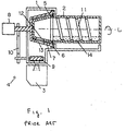
- FIG. 1 depicts a cross section of a toner supplying apparatus disclosed in laid open patent application number H04-1681.
- the frame 1 of a toner supplying apparatus is positioned above a development device 3.
- a toner bottle holder 5 is situated within the frame 1 with one end of the toner bottle holder 5 extending through the frame 1 and connected to a motor 8.
- One end or tip side of a toner bottle 2 is held in place by the toner bottle holder 5.
- a sealant 6 is seated between the toner bottle holder 5 and the frame 1.
- Another sealant 7 is seated between the toner bottle holder 5 and the toner bottle 2.
- a toner supplying roller 9 is positioned within the frame 1.
- the motor 8 is for rotating the toner bottle 2 via the toner bottle holder 5 and the toner supplying roller 9 via a gear 10.
- the toner bottle 2 contains toner 14 and has an opening 12 formed in the tip side of the toner bottle 2 for allowing the toner 14 to flow therefrom.
- An opening 13 is also formed in the toner bottle holder.
- the toner bottle 2 has a spiral rib 11 formed on inside wall thereof.
- a photosensitive drum is depicted by the numeral 4.
- the toner 14 When the toner bottle 2 is rotated around a horizontal axis L by the motor 8, the toner 14 is moved to the opening 12 by a transferring force derived from the spiral rib 11 on the toner bottle 2.
- the spiral rib 11 formed on an inner wall of toner bottle 2 transfers the toner 14 toward the opening 12.
- the toner 14 falls through the bottle holder opening 13 into the frame 1 of the toner supplying apparatus.
- the supply roller 9 rotates to feed a specified quantity of toner to the development device 3.
- toner bottle 2 When the toner bottle 2 empties, a user pulls out the toner bottle 2 and inserts a new toner bottle along the horizontal axis L as a replacement toner bottle. Since the opening 12 of toner bottle 2 slants, the toner bottle 2 contacts the sealant 7 when the toner bottle 2 is inserted completely into the toner bottle holder 5, thereby assuring a proper sealing.
- the toner supplying apparatus disclosed in laid open patent application number H04-1681 has certain disadvantages or problems. Specifically, since a terminal of the spiral rib 11 is away from the opening 12, the quantity of toner that flows out of the opening 12 is reduced or becomes unstable when the quantity of toner in the bottle becomes low. The toner flows smoothly only when there is a substantial amount of toner in the bottle. However, when the quantity of toner in the bottle is lowered, the amount of toner flowing from the openings 12, 13 is reduced. This causes the toner density of the development device 3 to become unstable, thereby lowering copy quality.
- Another disadvantage stems from the insertion of the toner bottle 2 into the toner bottle holder 5.
- the opening 12 of the toner bottle 2 Prior to insertion the opening 12 of the toner bottle 2 is covered by a thermal disposition sheet.
- the thermal disposition sheet must be peeled off before the toner bottle is mounted in the toner supplying apparatus.
- a user therefore, handles the toner bottle 2 with an uncovered opening 12 prior to the bottle's insertion into the holder.
- the user dirties his/her hands or peripheral devices by spilling some toner from the opening 12.
- the toner bottle 2 is removed from the apparatus with the opening 12 facing down, the toner left in the bottle gets spilled and dirties the toner supplying apparatus.
- the present invention changes the structure of the conventional toner bottle and aims to provide a toner bottle that can supply toner in stable and consistent manner when rotating the toner bottle.
- the present invention also aims to provide a toner bottle that avoids dirtying a user's hands or peripheral devices when the toner bottle is inserted or removed to/from the bottle holder, by fitting the opening of the toner bottle exactly to the counterpart of the bottle holder.
- the present invention further aims to provide a toner bottle from which the toner will not spill from its opening when the bottle is being handled.
- a toner bottle comprises, a body having an inner surface on which a continuous convex and spiral rib is formed, a tip portion having a side on which an opening is formed, a main unit between the body and the tip portion, said main unit having a first circular face having a convex sloped toward the inside of the body and a second circular face having a toner pump-up part whose diameter is approximately the same as that of the body, and a shutter rotatably disposed on the tip portion where the bottle opening is formed, the shutter normally closing the tip opening, wherein the shutter fits the opening of the tip portion over another opening formed on a toner supplying means when the toner bottle is mounted in a toner supplying means.
- Another toner bottle according to the present invention comprises, a toner bottle where an opening for toner flowing is disposed on its tip side, a shutter rotatably disposed for opening/closing the opening for toner flowing, wherein the shutter is made of elastic member and a part of the shutter is thicker than other parts so that the tip opening is closed by the thicker part of the shutter.
- Still another toner bottle comprises, a toner bottle where an opening for toner flowing is disposed on its tip side, a shutter having an opening that fits over the counterpart opening disposed on the bottle tip side, this shutter being rotatably disposed to open and close the counterpart tip opening.
- the periphery of the tip opening disposed on the tip side of the bottle is made up thicker than other peripheries, and the shutter is made of elastic member. The shutter normally closes the opening disposed on the bottle tip side, and fits both openings to each other when the toner bottle is mounted to a toner supplying means.
- another toner bottle comprises, a toner bottle where an opening for toner flowing is disposed on its tip side, a shutter having an opening that fits over the counterpart tip opening disposed on the bottle tip side, the shutter being rotatably disposed to open and close the counterpart tip opening.
- the periphery of the opening disposed on the tip side of the bottle is made up thicker than other peripheries, and the shutter is made of elastic member.
- the measurements of the tip and shuttter have the following relationship: R 1 > r 1 - e , r 2 > R 2, where R1 is the outer radius of the tip near the opening of the toner bottle, R2 is the outer radius near the toner bottle center, "e” is the distance of the deviation from the origin center of the circular arc of the shutter, and r1 is the inner radius having the center at "e", r2 is the inner radius near the opening of the toner bottle.
- another toner bottle comprises, a toner bottle where an opening for toner flowing is disposed on its tip side, a shutter having an opening that fits over the counterpart disposed on the bottle tip side, the shutter being rotatably disposed to open and close the counterpart, and a lid member detachably disposed at the tip of toner bottle, the lid member prevents the shutter from falling or coming off.
- a toner bottle other than the above according to the present invention comprises, a toner bottle where an opening toner flowing is disposed on its tip side, a shutter having an opening that fits over the counterpart disposed on the bottle tip side, the shutter being rotatably disposed to open and close the counterpart, and an elastic member disposed on an inside wall of the shutter.
- the toner bottle comprises, a body in which the convex and spiral rib is continuously formed on the inner face, a tip whose side has the opening for toner flowing, a part of the toner bottle between the body and tip, where a first circular face has the slope convex toward inside of the bottle, and a second circular face for toner pump-up whose diameter is approximately same as that of the body, and a shutter rotatably disposed on the tip where the opening is formed, the shutter normally closes the opening, and having an opening thereon which fits over the opening of the toner bottle when the toner bottle is mounted to a toner supplying means.
- An advantage of the present invention is obtained when mounting or removing the toner bottle to/from a toner supplying means.
- a user need not worry about dirtying his/her hands or peripheral devices.
- the above structure does not require a seal for covering the tip opening.
- the present invention saves the time it took to peel off the seal prior to inserting the toner bottle in a toner supplying device.
- the above structure also has the advantage of allowing toner to be supplied stably in a consistent and even manner by only rotating the toner bottle.
- Another toner bottle according to the present invention comprises, an elastic member on the inner wall of the shutter so that the toner bottle may have an improved airtightness between the outside of the tip and the inside of the shorter, as well as permitting the tip to slide more freely inside the shutter by reducing the friction therebetween.
- Fig. 1 is a cross section of a conventional toner supplying apparatus.
- Fig. 2 is a cross section of a toner supplying apparatus using a toner bottle of the present invention.
- Fig. 3 is a side view depicting how to mount/remove the toner bottle of the present invention.
- Figs. 4(a) and 4(b) are cross sections of the toner bottle of the present invention.
- Fig. 5 is a cross section of a shutter and a tip of the toner bottle of the present invention.
- Fig. 6 is a cross section of the tip of the toner bottle of the present invention.
- Fig. 7 is a cross section of a shutter of the present invention.
- Fig. 8 is a cross section depicting a relationship between the tip of a toner bottle and the shutter of the present invention when the opening in the tip of the toner bottle is uncovered.
- Fig. 9 is a cross section also depicting a relationship between the tip of toner bottle and the shutter of the present invention when the opening in the tip of the toner bottle is covered.
- Fig. 10 is a cross section depicting another exemplary embodiment of the shutter of the toner supplying apparatus of the present invention featuring an elastic layer on the inside of the shutter.
- Fig. 11 is a cross section depicting another exemplary embodiment of the toner bottle of the present invention featuring a lid for the tip of the toner bottle.
- Fig. 2 is a cross section of the toner supplying apparatus of the present invention.
- a toner bottle holder 17 which holds and rotates a toner bottle 15 containing toner(not shown).
- the toner bottle has an opening 19.
- the toner bottle holder has an opening 21.
- a shutter 16 is mounted to the tip of the toner bottle.
- the shutter has an opening 20.
- a hopper 18 holds the toner bottle holder 17 in a manner that permits the toner bottle holder to rotate.
- the hopper 18 also receives the toner 22 supplied by the toner bottle via the openings 19, 20 and 21.
- the opening 19 on the toner bottle, the opening 20 on the shutter, and the opening 21 on the toner bottle holder 17 coincide with each other and allow the toner 22 to be supplied to the hopper 18.
- a toner supplying roller 23 having plural notches 24 thereon is disposed in the hopper 18.
- the toner supplying roller 23 has a shaft 25.
- One end of the shaft 25 has a roller gear 26 thereon.
- Another end of the shaft 25 has a toner bottle holder gear 27 for rotating the toner bottle holder.
- a motor 28 is use to rotate the shaft 25.
- a driving gear 29 of the motor 28 engages the roller gear 26 so that the rotation can be transmitted to the shaft 23.
- a spring-loaded clutch 30 is wound around the bosses of the toner supplying roller 23 and the roller gear 26 for transmitting a rotation driving force via the roller gear 26 when the motor 28 rotates in a forward direction.
- a spring-loaded clutch 31 is wound around the bosses of the shaft 25 and the toner bottle holder gear 27 transmitting a rotation driving force when the motor 28 rotates in a reverse direction.
- the toner supplying roller 23 rotate independently when the motor 28 rotates forward
- the toner bottle holder gear 27 rotates independently when the motor 28 rotates in reverse.
- a cleaner 32 is rotated by the rotation of the toner supplying roller gear 26 via a driving gear 33 so that the cleaner 32 can clean the surface of a toner-remains-sensor 34.
- a development device 35 having an opening 36 in the lower portion of the hopper 18 for receiving the toner supplied to the lower portion of the hopper 18. Also, a screw 37 for feeding toner is situated in the lower portion of the hopper. Further, a screw 38 for agitating developing powder is situated adjacent the feeding screw 37. A toner density sensor 39 is situated at the bottom of the development device 35.
- a gear 40 mounted to the toner bottle holder 17 is so structured that the toner bottle holder gear 27 rotates the mounted toner bottle 15.
- Fig. 3 depicts side views of the toner bottle 15, the ring shutter 16, and the bottle toner holder 17.
- the toner bottle 15 has a body portion and a tip portion.
- the tip portion has an opening 19.
- the ring shutter 16 is rotatably disposed at the tip of toner bottle 15. Normally, the ring shutter 16 closes the opening 19 and prevents the toner from flowing out of the shutter's opening 20.
- the toner body holder 17 is shaped and sized to fit over toner bottle with the ring shutter 16 in place on the tip portion of the bottle.
- the toner bottle holder has a lower portion with an inner diameter larger than the diameter of the outer diameter of the toner bottle.
- the toner bottle holder 17 has an upper or tip portion with an inner diameter larger than the diameter of the outer diameter of the ring shutter 16.
- a convexly-shaped slit 44 for engagement with the protrusion 41 on the ring shutter 16.
- an opening 21 disposed on the upper portion of the toner bottle holder 17, which is shaped and sized to complement the opening 20 on the ring shutter, for allowing toner to flow from the toner bottle when the ring shutter 16 is rotated to a position where the opening 20 is disposed over the opening 19 in the toner bottle 15.
- the protrusion 42 is guided by the L-shape groove 43 to engage the toner bottle 15 with the toner bottle holder 17. Then the engaging protrusion 41 of the ring shutter 16 engages the convex slit 44 on the inside of toner bottle holder 17 to keep the ring shutter 16 from rotating relative to the toner bottle holder. However, the toner bottle 15 is free to rotate within the confines of the L-shaped slit 43 until the opening 19 in the toner bottle becomes aligned with the opening 20 in the ring shutter.
- the opening 19 coincides with the opening 20, which in turn coincides with the opening 21, and the toner bottle becomes mounted in the toner bottle holder 17 in a position that allows toner to flow from the toner bottle 15.
- the toner bottle 15 can be removed for replacement with another toner bottle.
- the arrangement just described has the advantage of keeping a toner bottle's opening 19 closed by the ring shutter 16 whenever a toner bottle is mounted or removed to/from the toner bottle holder 17, thus preventing the toner from spilling.
- users need not worry about dirtying their hands as well as dirtying the periphery devices.
- This arrangement also provides the advantage of eliminating the need to put a thermal deposition seal over the opening on a toner bottle. This saves time that was needed for peeling off the seal and facilitates the replacement of the toner bottles.
- the present invention utilizes a toner density sensor 39 for detecting any lowering of the toner density of the development device 35, as sheets are being copied.
- a detection signal is sent to the motor 28 to rotate the motor forward.
- the motor's rotation is transmitted via the driving gear 29 to the toner supplying roller gear 26 to rotate the shaft 25. Since the spring-loaded clutch 30 is disposed between the toner supplying roller gear 26 and the toner supplying roller 23, the rotation of shaft 25 is transmitted to the toner supplying roller 23, and the toner 25 in the notch 24 of the toner supplying roller 23 is supplied to the development device 35.
- the toner density sensor 39 detects an appropriate toner density, the motor 28 stops to end the supplying of toner to the toner development device 35.
- the present invention also utilizes a toner remaining sensor 34 for detecting any lowering of the quantity of toner in the hopper 18.
- a detection signal is sent to the motor 28 to rotate the motor in a reverse direction, which rotates the toner supplying roller gear 26 also in reverse.
- the reverse rotation is not transmitted to the toner supplying roller 23 because the spring-loaded clutch 30 slips.
- the spring-loaded clutch 31 is reversely wound between the shaft 25 and the toner bottle holder 27.
- the rotation driving force is transmitted therebetween to the gear 40 to rotate the toner bottle holder 17 and thus, the toner bottle 15.
- the toner bottle 15 as described in detail subsequently, has a continuous and convex spiral rib 45 on the inside thereof.
- the toner 22 inside the bottle moves toward the opening 19, and is supplied through the openings 20 and 21 to the hopper 18.
- the toner bottle 15 rotates once and stops. Then, the motor 28 rotates in reverse to supply the toner 22 from the toner bottle 15 to the hopper 18 until the toner remaining sensor 34 detects that the quantity of toner has reached a specified quantity.
- the detection level of the toner remaining sensor 34 is set to detect a point where the toner quantity level remains below the inner wall height of hopper 18 even after toner has been added following one rotation of the toner bottle 15. Therefore, the toner 22 never overflows the hopper 18.
- Fig. 4(a) is a cross section of an essential part of the toner bottle according to the present invention.
- Fig. 4(b) is a cross section of Fig. 4(a) taken along the line A-A.
- the shutter 16 is rotatably disposed at the tip of toner bottle 15.
- the opening 19 of the toner bottle 15 is normally closed by the shutter 16.
- a continuous, spiral rib 45 is formed on the inside of the body 15a of the toner bottle 15.
- the section has a slope 46, which is convex in shape sloping toward the inside of the body 15a and that is formed on a part of the section, and having a toner pump-up part 47, which has a diameter that is approximately the same as that of the body 15a and that is formed on the side of the section opposite from the slope 46.
- a toner pump-up part 47 when the toner pump-up part 47 is at a lower side or below a horizontal plane, the toner moved by the spiral rib 45 stays in the toner pump-up part 47.
- the toner pump-up part 47 rises to an upper side or above a horizontal plane with the opening 19 of the toner bottle 15 in the position shown in Fig. 2, the toner in the pump-up part 47 falls toward the slope 46 and slips on the slope 46 to the opening 19 permitting the toner to flow. As a result, the toner is supplied to the hopper 18.
- the present invention has the advantage of allowing the toner bottle 15 to transmit the toner with a constant or consistent quantity in a more stable or even manner than a toner bottle with a conventional spiral rib, as depicted in Fig. 1.
- Fig. 5 is a cross section depicting another exemplary embodiment of the present invention.
- the shutter 16, which is rotatably disposed on the toner bottle 15, is made of plastic so that the shutter 16 can be elastic.
- the shutter 16 is formed with an arc 16a that is thicker than the rest of the shutter.
- the opening 19 thereof is closed by the thicker arc 16a. Since the shutter 16 is elastic, the opening 19 is firmly closed by the thicker arc 16 although some gaps 48 are produced in other parts, thereby preventing the toner from spilling from the opening 19 through any gaps to dirty the user's hands or any periphery devices.
- the engaging protrusion 41 of the shutter 16 engages with the convex slit 44 of the toner bottle holder 17, thus keeping the shutter 16 from rotating relative to the toner bottle holder. Only the toner bottle 15 rotates to move the opening 19 of toner bottle 15 to the opening 20 of shutter 16. During such rotation, the inner diameter of the shutter becomes extended by the thickness of the thicker arc 16a. The shutter 16 deforms elastically by the gap 48 and the rotation of the toner bottle 15 is not impeded.
- Fig. 6 is a cross section of the tip of toner bottle 15.
- Fig. 7 is a cross section of shutter 16 for opening/closing the opening 19 of the toner bottle for allowing the toner to flow.
- the shutter 16 is mounted on the tip of toner bottle 15.
- the toner bottle 15 made of polyethylene, polypropylene, or vinyl chloride, and the tip thereof has two openings 19a, 19b from which toner may flow.
- the peripheries 15d of openings 19a, 19b are thicker than the other arc portions of the tip.
- the outer radius R1 is designed to be longer than the outer radius R2 of the arc 15b at the approximate center.
- An arc 15c between the two openings 19 is formed with radiuses continuously and gradually changing from R1 to R2.
- a first end "m" of periphery of the first opening 19a is made thicker than a second end "n" of the second opening 19b.
- the thickness of the arc increases gradually and continuously from "n" to "m".
- the counterpart arc on the other side is formed in the same manner.
- the shape of this thicker arc is not limited to the embodiment depicted in Fig. 6, but the shape may be in any form as long as the periphery 15d of the openings 19a, 19b are made thicker than the other peripheries of the tip portion of the toner bottle.
- two openings 20a, 20b and two protrusions 41a, 41b are formed in the shutter 16.
- An arc 16c (sealed part) is formed with an inner radius of r1 having a center that is P, which is deviated from the origin center 0 by "e".
- a periphery 16b containing the opening 20b is formed with an inner radius r2 from the origin center 0.
- Fig. 8 and Fig. 9 are cross sections depicting the shutter 16 in different positions relative to the toner bottle 15. Specifically, Fig. 8 depicts that the shutter 16 in an open position, and Fig. 9 depicts that the shutter 16 in a closed position.
- the radius r1 of the arc 16a (sealed part) situated between the openings 20 has the following relationship with the radius R1 of the periphery 15d of an opening in the toner bottle: R1 > r1 - e
- the shutter 16 which may be made of polypropylene, polyethylene, ABS resin or polystyrene is deformed elastically.
- the shutter 16 can close the opening 19 of toner bottle 15 firmly with the arc 16a thereof, thereby preventing the toner bottle 15 from spilling the toner accidentally.
- the inner radius r2 of periphery 16b containing an opening on the shutter 16 has the following relationship with the outer radius R2 of arc 15b of the toner bottle 15: r2 > R2
- the shutter 16 elastically deforms itself by the distance of gap 48 between the toner bottle 15 and the shutter. Hence, the shutter 16 can open/close smoothly without affecting the rotating operation of the shutter 16.
- the engaging protrusion 41 engages with the convex slit 44 of toner bottle holder 17. Accordingly, the shutter 16 does not rotate and only the toner bottle 15 rotates to move its opening 19 under the opening 20 of shutter 16. When the openings of the toner bottle and the shutter are in this position, toner may be supplied from the toner bottle 15 to the development device 35.
- Fig. 10 is a cross section depicting another embodiment of shutter 16.
- an elastic member such as a sponge or rubber is situated on the inside wall of the arc portion (sealed part) of the shutter 16 to provide a close airtightness.
- an elastic sealing member 49 made of foamed rubber, such as urethane-sponge, and a sliding sheet 50, form a dual-layer sealing member. This sealing member is put on the inner wall of arc 16c to increase airtightness as well to make it easier to rotate the toner bottle relative to the shutter ring, as by reducing the friction between the arc portion of the shutter and the toner bottle.
- Fig. 11 is a cross section depicting still another embodiment of a toner bottle according to the present invention.
- the opening on the tip of the toner bottle 15 is covered by a lid 51 made of the same resin material as that of the toner bottle 15.
- the lid 51 is detachable from the tip for loading the toner bottle 15 with toner.
- the lid 51 is capped onto the tip of toner bottle 15 with a collar 52 of lid 51.
- the outer diameter of collar 52 is larger than that of the toner bottle tip.
- the toner bottle 15 when inserting the shutter 16, the toner bottle 15 can be rotatably held with the shoulder part thereof, the lid 51, and the collar 52. As a result, a complex mechanism of rotatable holder can be omitted.
Abstract
Description
- The present invention relates to a toner bottle, which supplies toner to a development device of an electrophotographic copier or a printer, and a toner supplying apparatus using the toner bottle.
- Better copy quality has been demanded recently for electro-photographic copiers and printers. One of the measures for improving copy quality is to supply toner in a constant quantity automatically from a hopper to the development device.
- A conventional toner supplying apparatus is described by referring to Fig. 1, which depicts a cross section of a toner supplying apparatus disclosed in laid open patent application number H04-1681. In Fig. 1, the
frame 1 of a toner supplying apparatus is positioned above adevelopment device 3. Atoner bottle holder 5 is situated within theframe 1 with one end of thetoner bottle holder 5 extending through theframe 1 and connected to a motor 8. One end or tip side of atoner bottle 2 is held in place by thetoner bottle holder 5. A sealant 6 is seated between thetoner bottle holder 5 and theframe 1. Anothersealant 7 is seated between thetoner bottle holder 5 and thetoner bottle 2. A toner supplying roller 9 is positioned within theframe 1. The motor 8 is for rotating thetoner bottle 2 via thetoner bottle holder 5 and the toner supplying roller 9 via agear 10. Thetoner bottle 2 containstoner 14 and has anopening 12 formed in the tip side of thetoner bottle 2 for allowing thetoner 14 to flow therefrom. Anopening 13 is also formed in the toner bottle holder. Thetoner bottle 2 has aspiral rib 11 formed on inside wall thereof. A photosensitive drum is depicted by thenumeral 4. - When the
toner bottle 2 is rotated around a horizontal axis L by the motor 8, thetoner 14 is moved to theopening 12 by a transferring force derived from thespiral rib 11 on thetoner bottle 2. Thespiral rib 11 formed on an inner wall oftoner bottle 2 transfers thetoner 14 toward theopening 12. Thetoner 14 falls through the bottle holder opening 13 into theframe 1 of the toner supplying apparatus. Finally, the supply roller 9 rotates to feed a specified quantity of toner to thedevelopment device 3. - When the
toner bottle 2 empties, a user pulls out thetoner bottle 2 and inserts a new toner bottle along the horizontal axis L as a replacement toner bottle. Since the opening 12 oftoner bottle 2 slants, thetoner bottle 2 contacts thesealant 7 when thetoner bottle 2 is inserted completely into thetoner bottle holder 5, thereby assuring a proper sealing. - However, the toner supplying apparatus disclosed in laid open patent application number H04-1681 has certain disadvantages or problems. Specifically, since a terminal of the
spiral rib 11 is away from theopening 12, the quantity of toner that flows out of theopening 12 is reduced or becomes unstable when the quantity of toner in the bottle becomes low. The toner flows smoothly only when there is a substantial amount of toner in the bottle. However, when the quantity of toner in the bottle is lowered, the amount of toner flowing from theopenings development device 3 to become unstable, thereby lowering copy quality. - Another disadvantage stems from the insertion of the
toner bottle 2 into thetoner bottle holder 5. Prior to insertion the opening 12 of thetoner bottle 2 is covered by a thermal disposition sheet. The thermal disposition sheet must be peeled off before the toner bottle is mounted in the toner supplying apparatus. A user, therefore, handles thetoner bottle 2 with anuncovered opening 12 prior to the bottle's insertion into the holder. As a result, the user dirties his/her hands or peripheral devices by spilling some toner from the opening 12. - Also, if the
toner bottle 2 is removed from the apparatus with the opening 12 facing down, the toner left in the bottle gets spilled and dirties the toner supplying apparatus. - The present invention changes the structure of the conventional toner bottle and aims to provide a toner bottle that can supply toner in stable and consistent manner when rotating the toner bottle.
- The present invention also aims to provide a toner bottle that avoids dirtying a user's hands or peripheral devices when the toner bottle is inserted or removed to/from the bottle holder, by fitting the opening of the toner bottle exactly to the counterpart of the bottle holder.
- The present invention further aims to provide a toner bottle from which the toner will not spill from its opening when the bottle is being handled.
- A toner bottle according to the present invention comprises, a body having an inner surface on which a continuous convex and spiral rib is formed, a tip portion having a side on which an opening is formed, a main unit between the body and the tip portion, said main unit having a first circular face having a convex sloped toward the inside of the body and a second circular face having a toner pump-up part whose diameter is approximately the same as that of the body, and a shutter rotatably disposed on the tip portion where the bottle opening is formed, the shutter normally closing the tip opening, wherein the shutter fits the opening of the tip portion over another opening formed on a toner supplying means when the toner bottle is mounted in a toner supplying means.
- Another toner bottle according to the present invention comprises, a toner bottle where an opening for toner flowing is disposed on its tip side, a shutter rotatably disposed for opening/closing the opening for toner flowing, wherein the shutter is made of elastic member and a part of the shutter is thicker than other parts so that the tip opening is closed by the thicker part of the shutter.
- Still another toner bottle according to the present invention comprises, a toner bottle where an opening for toner flowing is disposed on its tip side, a shutter having an opening that fits over the counterpart opening disposed on the bottle tip side, this shutter being rotatably disposed to open and close the counterpart tip opening. The periphery of the tip opening disposed on the tip side of the bottle is made up thicker than other peripheries, and the shutter is made of elastic member. The shutter normally closes the opening disposed on the bottle tip side, and fits both openings to each other when the toner bottle is mounted to a toner supplying means.
- Further, another toner bottle according to the present invention comprises, a toner bottle where an opening for toner flowing is disposed on its tip side, a shutter having an opening that fits over the counterpart tip opening disposed on the bottle tip side, the shutter being rotatably disposed to open and close the counterpart tip opening. The periphery of the opening disposed on the tip side of the bottle is made up thicker than other peripheries, and the shutter is made of elastic member. In this embodiment, the measurements of the tip and shuttter have the following relationship:

r 2 >R 2, where R1 is the outer radius of the tip near the opening of the toner bottle, R2 is the outer radius near the toner bottle center, "e" is the distance of the deviation from the origin center of the circular arc of the shutter, and r1 is the inner radius having the center at "e", r2 is the inner radius near the opening of the toner bottle. - Still further, another toner bottle according to the present invention comprises, a toner bottle where an opening for toner flowing is disposed on its tip side, a shutter having an opening that fits over the counterpart disposed on the bottle tip side, the shutter being rotatably disposed to open and close the counterpart, and a lid member detachably disposed at the tip of toner bottle, the lid member prevents the shutter from falling or coming off..
- A toner bottle other than the above according to the present invention comprises, a toner bottle where an opening toner flowing is disposed on its tip side, a shutter having an opening that fits over the counterpart disposed on the bottle tip side, the shutter being rotatably disposed to open and close the counterpart, and an elastic member disposed on an inside wall of the shutter.
- According to the present invention, the toner bottle comprises, a body in which the convex and spiral rib is continuously formed on the inner face, a tip whose side has the opening for toner flowing, a part of the toner bottle between the body and tip, where a first circular face has the slope convex toward inside of the bottle, and a second circular face for toner pump-up whose diameter is approximately same as that of the body, and a shutter rotatably disposed on the tip where the opening is formed, the shutter normally closes the opening, and having an opening thereon which fits over the opening of the toner bottle when the toner bottle is mounted to a toner supplying means.
- An advantage of the present invention is obtained when mounting or removing the toner bottle to/from a toner supplying means. A user need not worry about dirtying his/her hands or peripheral devices. In particular. the above structure does not require a seal for covering the tip opening. Thus, the present invention saves the time it took to peel off the seal prior to inserting the toner bottle in a toner supplying device. The above structure also has the advantage of allowing toner to be supplied stably in a consistent and even manner by only rotating the toner bottle.
- Another toner bottle according to the present invention comprises, an elastic member on the inner wall of the shutter so that the toner bottle may have an improved airtightness between the outside of the tip and the inside of the shorter, as well as permitting the tip to slide more freely inside the shutter by reducing the friction therebetween.
- The invention itself, together with further objects and attendant advantages, will best be understood by reference to the following detailed description taken in conjunction with the accompanying figures.
- Fig. 1 is a cross section of a conventional toner supplying apparatus.
- Fig. 2 is a cross section of a toner supplying apparatus using a toner bottle of the present invention.
- Fig. 3 is a side view depicting how to mount/remove the toner bottle of the present invention.
- Figs. 4(a) and 4(b) are cross sections of the toner bottle of the present invention.
- Fig. 5 is a cross section of a shutter and a tip of the toner bottle of the present invention.
- Fig. 6 is a cross section of the tip of the toner bottle of the present invention.
- Fig. 7 is a cross section of a shutter of the present invention.
- Fig. 8 is a cross section depicting a relationship between the tip of a toner bottle and the shutter of the present invention when the opening in the tip of the toner bottle is uncovered.
- Fig. 9 is a cross section also depicting a relationship between the tip of toner bottle and the shutter of the present invention when the opening in the tip of the toner bottle is covered.
- Fig. 10 is a cross section depicting another exemplary embodiment of the shutter of the toner supplying apparatus of the present invention featuring an elastic layer on the inside of the shutter.
- Fig. 11 is a cross section depicting another exemplary embodiment of the toner bottle of the present invention featuring a lid for the tip of the toner bottle.
- An exemplary embodiment of the present invention is described by referring to the drawings attached.
- Fig. 2 is a cross section of the toner supplying apparatus of the present invention. In Fig. 2, there is shown a
toner bottle holder 17, which holds and rotates atoner bottle 15 containing toner(not shown). The toner bottle has anopening 19. The toner bottle holder has anopening 21. Ashutter 16 is mounted to the tip of the toner bottle. The shutter has anopening 20. Ahopper 18 holds thetoner bottle holder 17 in a manner that permits the toner bottle holder to rotate. Thehopper 18 also receives thetoner 22 supplied by the toner bottle via theopenings - When the
toner bottle 15 is mounted to thetoner bottle holder 17, theopening 19 on the toner bottle, theopening 20 on the shutter, and theopening 21 on thetoner bottle holder 17 coincide with each other and allow thetoner 22 to be supplied to thehopper 18. - A
toner supplying roller 23 havingplural notches 24 thereon is disposed in thehopper 18. Thetoner supplying roller 23 has ashaft 25. One end of theshaft 25 has aroller gear 26 thereon. Another end of theshaft 25 has a tonerbottle holder gear 27 for rotating the toner bottle holder. Amotor 28 is use to rotate theshaft 25. In particular, adriving gear 29 of themotor 28 engages theroller gear 26 so that the rotation can be transmitted to theshaft 23. A spring-loadedclutch 30 is wound around the bosses of thetoner supplying roller 23 and theroller gear 26 for transmitting a rotation driving force via theroller gear 26 when themotor 28 rotates in a forward direction. A spring-loadedclutch 31 is wound around the bosses of theshaft 25 and the tonerbottle holder gear 27 transmitting a rotation driving force when themotor 28 rotates in a reverse direction. Thus, thetoner supplying roller 23 rotate independently when themotor 28 rotates forward, and the tonerbottle holder gear 27 rotates independently when themotor 28 rotates in reverse. - A cleaner 32 is rotated by the rotation of the toner supplying
roller gear 26 via adriving gear 33 so that the cleaner 32 can clean the surface of a toner-remains-sensor 34. - There is a
development device 35 having anopening 36 in the lower portion of thehopper 18 for receiving the toner supplied to the lower portion of thehopper 18. Also, ascrew 37 for feeding toner is situated in the lower portion of the hopper. Further, ascrew 38 for agitating developing powder is situated adjacent the feedingscrew 37. Atoner density sensor 39 is situated at the bottom of thedevelopment device 35. - A
gear 40 mounted to thetoner bottle holder 17 is so structured that the tonerbottle holder gear 27 rotates the mountedtoner bottle 15. - Fig. 3 depicts side views of the
toner bottle 15, thering shutter 16, and thebottle toner holder 17. As depicted in Fig. 3, thetoner bottle 15 has a body portion and a tip portion. The tip portion has anopening 19. Below theopening 19, there is aprotrusion 42 on the main portion of thetoner bottle 15. Thering shutter 16 is rotatably disposed at the tip oftoner bottle 15. Normally, thering shutter 16 closes theopening 19 and prevents the toner from flowing out of the shutter'sopening 20. There is anopening 20 disposed on thering shutter 16, which is shaped and sized to complement theopening 19, for allowing toner to flow from the toner bottle when thering shutter 16 is rotated to a position where theopening 20 is disposed over theopening 19. An engagingprotrusion 41 is formed on thering shutter 16. Thetoner body holder 17 is shaped and sized to fit over toner bottle with thering shutter 16 in place on the tip portion of the bottle. The toner bottle holder has a lower portion with an inner diameter larger than the diameter of the outer diameter of the toner bottle. On the side of the lower portion of thetoner bottle holder 17, there is formed an L-shape groove 43 for engagement with theprotrusion 42 on thetoner bottle 15. Further, thetoner bottle holder 17 has an upper or tip portion with an inner diameter larger than the diameter of the outer diameter of thering shutter 16. On the inside of the upper portion of thetoner bottle holder 17, there is formed a convexly-shapedslit 44 for engagement with theprotrusion 41 on thering shutter 16. Also, there is anopening 21 disposed on the upper portion of thetoner bottle holder 17, which is shaped and sized to complement theopening 20 on the ring shutter, for allowing toner to flow from the toner bottle when thering shutter 16 is rotated to a position where theopening 20 is disposed over theopening 19 in thetoner bottle 15. - When the
toner bottle 15 is inserted into thetoner bottle holder 17, theprotrusion 42 is guided by the L-shape groove 43 to engage thetoner bottle 15 with thetoner bottle holder 17. Then the engagingprotrusion 41 of thering shutter 16 engages theconvex slit 44 on the inside oftoner bottle holder 17 to keep thering shutter 16 from rotating relative to the toner bottle holder. However, thetoner bottle 15 is free to rotate within the confines of the L-shapedslit 43 until theopening 19 in the toner bottle becomes aligned with theopening 20 in the ring shutter. - As a result, the
opening 19 coincides with theopening 20, which in turn coincides with theopening 21, and the toner bottle becomes mounted in thetoner bottle holder 17 in a position that allows toner to flow from thetoner bottle 15. When the above procedure is reversed thetoner bottle 15 can be removed for replacement with another toner bottle. The arrangement just described has the advantage of keeping a toner bottle'sopening 19 closed by thering shutter 16 whenever a toner bottle is mounted or removed to/from thetoner bottle holder 17, thus preventing the toner from spilling. As a result, users need not worry about dirtying their hands as well as dirtying the periphery devices. This arrangement also provides the advantage of eliminating the need to put a thermal deposition seal over the opening on a toner bottle. This saves time that was needed for peeling off the seal and facilitates the replacement of the toner bottles. - Now returning to Fig. 2, the present invention utilizes a
toner density sensor 39 for detecting any lowering of the toner density of thedevelopment device 35, as sheets are being copied. When a change in toner density is detected, a detection signal is sent to themotor 28 to rotate the motor forward. The motor's rotation is transmitted via thedriving gear 29 to the toner supplyingroller gear 26 to rotate theshaft 25. Since the spring-loadedclutch 30 is disposed between the toner supplyingroller gear 26 and thetoner supplying roller 23, the rotation ofshaft 25 is transmitted to thetoner supplying roller 23, and thetoner 25 in thenotch 24 of thetoner supplying roller 23 is supplied to thedevelopment device 35. Then, when thetoner density sensor 39 detects an appropriate toner density, themotor 28 stops to end the supplying of toner to thetoner development device 35. - The present invention also utilizes a
toner remaining sensor 34 for detecting any lowering of the quantity of toner in thehopper 18. When a change in the quantity of toner is detected, a detection signal is sent to themotor 28 to rotate the motor in a reverse direction, which rotates the toner supplyingroller gear 26 also in reverse. However, the reverse rotation is not transmitted to thetoner supplying roller 23 because the spring-loaded clutch 30 slips. Instead, the spring-loadedclutch 31 is reversely wound between theshaft 25 and thetoner bottle holder 27. Thus the rotation driving force is transmitted therebetween to thegear 40 to rotate thetoner bottle holder 17 and thus, thetoner bottle 15. - The
toner bottle 15, as described in detail subsequently, has a continuous andconvex spiral rib 45 on the inside thereof. When thetoner bottle 15 rotates, thetoner 22 inside the bottle moves toward theopening 19, and is supplied through theopenings hopper 18. - The
toner bottle 15 rotates once and stops. Then, themotor 28 rotates in reverse to supply thetoner 22 from thetoner bottle 15 to thehopper 18 until thetoner remaining sensor 34 detects that the quantity of toner has reached a specified quantity. The detection level of thetoner remaining sensor 34 is set to detect a point where the toner quantity level remains below the inner wall height ofhopper 18 even after toner has been added following one rotation of thetoner bottle 15. Therefore, thetoner 22 never overflows thehopper 18. - The structure of
toner bottle 15, according to the present invention, is described by referring to Fig. 4(a) and Fig. 4(b). Fig. 4(a) is a cross section of an essential part of the toner bottle according to the present invention. Fig. 4(b) is a cross section of Fig. 4(a) taken along the line A-A. As pointed out above, theshutter 16 is rotatably disposed at the tip oftoner bottle 15. Theopening 19 of thetoner bottle 15 is normally closed by theshutter 16. A continuous,spiral rib 45 is formed on the inside of thebody 15a of thetoner bottle 15. Thus, when thetoner bottle 15 rotates, the toner inside the bottle moves toward theopening 19. Between thebody 15a and theopening 19, there is a section joining thebody 15a and the tip. The section has aslope 46, which is convex in shape sloping toward the inside of thebody 15a and that is formed on a part of the section, and having a toner pump-uppart 47, which has a diameter that is approximately the same as that of thebody 15a and that is formed on the side of the section opposite from theslope 46. As shown in Fig. 4(a), when the toner pump-uppart 47 is at a lower side or below a horizontal plane, the toner moved by thespiral rib 45 stays in the toner pump-uppart 47. However, when thetoner bottle 15 rotates and the toner pump-uppart 47 rises to an upper side or above a horizontal plane with theopening 19 of thetoner bottle 15 in the position shown in Fig. 2, the toner in the pump-uppart 47 falls toward theslope 46 and slips on theslope 46 to theopening 19 permitting the toner to flow. As a result, the toner is supplied to thehopper 18. - Since the toner is forced to flow out using the
slope 46, the present invention has the advantage of allowing thetoner bottle 15 to transmit the toner with a constant or consistent quantity in a more stable or even manner than a toner bottle with a conventional spiral rib, as depicted in Fig. 1. - Fig. 5 is a cross section depicting another exemplary embodiment of the present invention. The
shutter 16, which is rotatably disposed on thetoner bottle 15, is made of plastic so that theshutter 16 can be elastic. Theshutter 16 is formed with anarc 16a that is thicker than the rest of the shutter. When thetoner bottle 15 is not in use, theopening 19 thereof is closed by thethicker arc 16a. Since theshutter 16 is elastic, theopening 19 is firmly closed by thethicker arc 16 although somegaps 48 are produced in other parts, thereby preventing the toner from spilling from theopening 19 through any gaps to dirty the user's hands or any periphery devices. - When the
toner bottle 15 is put in use, the engagingprotrusion 41 of theshutter 16 engages with theconvex slit 44 of thetoner bottle holder 17, thus keeping theshutter 16 from rotating relative to the toner bottle holder. Only thetoner bottle 15 rotates to move theopening 19 oftoner bottle 15 to theopening 20 ofshutter 16. During such rotation, the inner diameter of the shutter becomes extended by the thickness of thethicker arc 16a. Theshutter 16 deforms elastically by thegap 48 and the rotation of thetoner bottle 15 is not impeded. - Further, another exemplary embodiment is described by referring to Figs. 6-9.
- Fig. 6 is a cross section of the tip of
toner bottle 15. Fig. 7 is a cross section ofshutter 16 for opening/closing theopening 19 of the toner bottle for allowing the toner to flow. Theshutter 16 is mounted on the tip oftoner bottle 15. - In Fig. 6, the
toner bottle 15 made of polyethylene, polypropylene, or vinyl chloride, and the tip thereof has two openings 19a, 19b from which toner may flow. The peripheries 15d of openings 19a, 19b are thicker than the other arc portions of the tip. The outer radius R1 is designed to be longer than the outer radius R2 of the arc 15b at the approximate center. An arc 15c between the twoopenings 19 is formed with radiuses continuously and gradually changing from R1 to R2. To be more specific, a first end "m" of periphery of the first opening 19a is made thicker than a second end "n" of the second opening 19b. The thickness of the arc increases gradually and continuously from "n" to "m". The counterpart arc on the other side is formed in the same manner. The shape of this thicker arc is not limited to the embodiment depicted in Fig. 6, but the shape may be in any form as long as the periphery 15d of the openings 19a, 19b are made thicker than the other peripheries of the tip portion of the toner bottle. - As shown in Fig. 7, two
openings 20a, 20b and twoprotrusions 41a, 41b are formed in theshutter 16. Anarc 16c (sealed part) is formed with an inner radius of r1 having a center that is P, which is deviated from theorigin center 0 by "e". A periphery 16b containing theopening 20b is formed with an inner radius r2 from theorigin center 0. - Fig. 8 and Fig. 9 are cross sections depicting the
shutter 16 in different positions relative to thetoner bottle 15. Specifically, Fig. 8 depicts that theshutter 16 in an open position, and Fig. 9 depicts that theshutter 16 in a closed position. - As described before, the radius r1 of the
arc 16a (sealed part) situated between theopenings 20 has the following relationship with the radius R1 of the periphery 15d of an opening in the toner bottle:
- Based on the above relation, the
shutter 16, which may be made of polypropylene, polyethylene, ABS resin or polystyrene is deformed elastically. Thus, theshutter 16 can close theopening 19 oftoner bottle 15 firmly with thearc 16a thereof, thereby preventing thetoner bottle 15 from spilling the toner accidentally. - The inner radius r2 of periphery 16b containing an opening on the
shutter 16 has the following relationship with the outer radius R2 of arc 15b of the toner bottle 15: r2 > R2 - Accordingly, as shown in Fig. 8, the
shutter 16 elastically deforms itself by the distance ofgap 48 between thetoner bottle 15 and the shutter. Hence, theshutter 16 can open/close smoothly without affecting the rotating operation of theshutter 16. - When the
toner bottle 15 is fitted in the toner bottle holder, the engagingprotrusion 41 engages with theconvex slit 44 oftoner bottle holder 17. Accordingly, theshutter 16 does not rotate and only thetoner bottle 15 rotates to move itsopening 19 under theopening 20 ofshutter 16. When the openings of the toner bottle and the shutter are in this position, toner may be supplied from thetoner bottle 15 to thedevelopment device 35. - Fig. 10 is a cross section depicting another embodiment of
shutter 16. In this embodiment, an elastic member such as a sponge or rubber is situated on the inside wall of the arc portion (sealed part) of theshutter 16 to provide a close airtightness. To be more specific, anelastic sealing member 49 made of foamed rubber, such as urethane-sponge, and a sliding sheet 50, form a dual-layer sealing member. This sealing member is put on the inner wall ofarc 16c to increase airtightness as well to make it easier to rotate the toner bottle relative to the shutter ring, as by reducing the friction between the arc portion of the shutter and the toner bottle. - Fig. 11 is a cross section depicting still another embodiment of a toner bottle according to the present invention. The opening on the tip of the
toner bottle 15 is covered by alid 51 made of the same resin material as that of thetoner bottle 15. Thelid 51 is detachable from the tip for loading thetoner bottle 15 with toner. Thelid 51 is capped onto the tip oftoner bottle 15 with a collar 52 oflid 51. The outer diameter of collar 52 is larger than that of the toner bottle tip. Thus, theshutter 16 is prevented from coming off the tip and its movement is confined to a rotatable movement around the tip. - According to the above structure, when inserting the
shutter 16, thetoner bottle 15 can be rotatably held with the shoulder part thereof, thelid 51, and the collar 52. As a result, a complex mechanism of rotatable holder can be omitted. - Of course, it should be understood that a wide range of changes and modifications can be made to the preferred embodiment described above and that the foregoing description be regarded as illustrative rather than limiting. It is therefore intended that it is the following claims, including all equivalents, which are intended to define the scope of this invention.
Claims (12)
- A toner bottle comprising:(a) a body having a convexly-shaped spiral rib formed continuously on the inside face thereof;(b) a tip having an opening in a side thereof for allowing toner to flow;(c) a section joining said body and said tip having a first circular face with a convexly shaped slope sloping toward the inside of the section, and a second circular face with a toner pump-up portion having a diameter that is approximately the same as that of said body; and(d) a shutter rotatably disposed on said tip where the tip opening is formed, said shutter having an opening,wherein said shutter normally closes the tip opening, except when the tip opening is moved under the shutter opening.
- A toner bottle comprising;(a) a bottle having a tip with an opening for toner to flow therefrom; and(b) a shutter having an opening,wherein the tip opening is closed by the thicker arc of said shutter.said shutter rotatably disposed over the tip for closing and opening the tip opening,said shutter being made of elastic, andsaid shutter having an arc part that is made thicker than other parts of the shutter,
- A toner bottle comprising:(a) a bottle having a tip with an opening therein for allowing toner to flow from the bottle,wherein a periphery of the tip opening is made thicker than other peripheries of the tip; and(b) a shutter rotatably disposed on the tip for opening and closing the tip opening,wherein said shutter has an opening that fits over the tip opening,
wherein said shutter is elastic and normally closes the tip opening, except when the tip opening is moved under the shutter opening. - A toner bottle comprising:(a) a bottle having a tip with an opening therein for allowing toner to flow from the bottle;wherein a periphery of the tip opening is made gradually thicker from a first part of a circle to a second part thereof; and(b) a shutter rotatably disposed on the tip for opening and closing the tip opening,wherein said shutter has an opening that fits over the tip opening,
wherein said shutter is elastic and normally closes the tip opening, except when the tip opening is moved under the shutter opening. - A toner bottle comprising:(a) a bottle having a tip with an opening therein for allowing toner to flow from the bottle,wherein a periphery of the tip opening is made thicker than other peripheries of the tip; and(b) a shutter rotatably disposed on the tip for opening and closing the tip opening,wherein said shutter has an opening that fits over the tip opening,
wherein said shutter is elastic and normally closes the tip opening, except when the tip opening is moved under the shutter opening, and wherein the tip and shutter have the following relationship: R1 is the outer radius of the periphery of the tip opening of the toner bottle,R2 is the outer radius of the approximate center of the tip,r1 is the inner radius of an arc of the shutter taken from a center of the shutter that is deviated from an origin center of the shutter by a distance "e", andr2 is the inner radius of a periphery of the shutter opening the origin center of the shutter.
 - A toner bottle comprising:(a) a bottle having a tip with an opening for toner to flow therefrom;(b) a shutter having an opening,said shutter rotatably disposed over the tip for closing and opening the tip opening; and(c) a lid detachably disposed on the tip of said bottle, for preventing said shutter from falling off the tip.
- The toner bottle of Claim 6,
wherein said lid has a collar with a diameter that is larger than the diameter of the tip of the toner bottle. - A toner bottle comprising:(a) a bottle having a tip with an opening therein for allowing toner to flow from the bottle;wherein a periphery of the tip opening is made gradually thicker from a first part of a circle to a second part thereof; and(b) a shutter rotatably disposed on the tip for opening and closing the tip opening,wherein said shutter has an opening that fits over the tip opening,
wherein said shutter is elastic and normally closes the tip opening, except when the tip opening is rotated under the shutter opening, and
wherein said shutter has an elastic member on an inside wall thereof to reduce friction between the tip and the shutter during rotation. - The toner bottle of Claim 8,
wherein said elastic member comprises dual layers comprising an elastic sealing member and a sliding sheet. - A toner supplying apparatus comprising:(a) a toner bottle held by a bottle holder, said bottle having an opening therein for allowing toner to flow therefrom through an opening in the bottle holder;(b) a hopper for holding the bottle holder and for rotating the bottle holder;(c) a rotatable shaft capable of being rotated in a forward direction and in a reverse direction;(d) a toner supplying roller disposed in said hopper for supplying toner to a development device when said rotating shaft rotates forward; and(e) rotating means for rotating said bottle holder when said rotating shaft rotates in reverse and for allowing toner to flow from the toner bottle to the hopper,wherein said toner bottle comprises:(i) a body having a convexly-shaped spiral rib continuously formed on the inside face thereof;(ii) a tip with an opening therein for allowing toner to flow from the bottle;(iii) a section joining the body and the tip comprising,a first circular face having a convex portion sloping toward the inside, anda second circular face having a toner pump-up portion wit a diameter that is approximately the same as that of the body; and(iv) a shutter having an opening,said shutter rotatably disposed over the tip for closing and opening the tip opening.
- The toner supplying apparatus of Claim 10,
wherein a protrusion is formed on a side of said shutter and a convex slit is formed on an inside face of the bottle holder, and
wherein when the toner bottle is inserted into the bottle holder, the protrusion formed on the shutter engages said convex slit to prevent the shutter from rotating independently of the bottle holder. - A toner bottle comprising:(a) a body having a convexly-shaped spiral rib continuously formed on the inside face thereof;(b) a tip with an opening therein for allowing toner to flow therefrom;(c) a section joining the body and the tip comprising,a first circular face having a convex portion sloping toward the inside, anda second circular face having a toner pump-up portion wit a diameter that is approximately the same as that of the body; and(d) a shutter having an opening,said shutter rotatably disposed over the tip for closing and opening the tip opening.
Applications Claiming Priority (3)
| Application Number | Priority Date | Filing Date | Title |
|---|---|---|---|
| JP5573696 | 1996-03-13 | ||
| JP55736/96 | 1996-03-13 | ||
| JP08055736A JP3120723B2 (en) | 1996-03-13 | 1996-03-13 | Toner container and copying machine using the same |
Publications (3)
| Publication Number | Publication Date |
|---|---|
| EP0801337A2 true EP0801337A2 (en) | 1997-10-15 |
| EP0801337A3 EP0801337A3 (en) | 1997-12-29 |
| EP0801337B1 EP0801337B1 (en) | 2003-07-30 |
Family
ID=13007148
Family Applications (1)
| Application Number | Title | Priority Date | Filing Date |
|---|---|---|---|
| EP97103826A Expired - Lifetime EP0801337B1 (en) | 1996-03-13 | 1997-03-07 | Toner bottle and toner supplying apparatus using the same |
Country Status (7)
| Country | Link |
|---|---|
| US (1) | US5774773A (en) |
| EP (1) | EP0801337B1 (en) |
| JP (1) | JP3120723B2 (en) |
| KR (1) | KR100335687B1 (en) |
| CN (1) | CN1103941C (en) |
| DE (1) | DE69723755T2 (en) |
| TW (1) | TW402697B (en) |
Cited By (6)
| Publication number | Priority date | Publication date | Assignee | Title |
|---|---|---|---|---|
| EP0856780A1 (en) * | 1997-01-30 | 1998-08-05 | Konica Corporation | Developing agent replenishing device and image forming apparatus with the device |
| EP1403733A1 (en) * | 2002-09-24 | 2004-03-31 | Ricoh Company, Ltd. | Image forming apparatus with a toner container replenishing a process cartridge |
| WO2004077170A1 (en) * | 2003-02-28 | 2004-09-10 | Ricoh Company, Ltd. | Developer container, developer supplying device, and image forming apparatus |
| US7313349B2 (en) | 2004-02-06 | 2007-12-25 | Ricoh Company, Ltd. | Toner container and image forming apparatus |
| US7466945B2 (en) | 2004-03-05 | 2008-12-16 | Ricoh Company, Ltd. | Toner container, toner replenishing device, developing device, process cartridge and image forming apparatus |
| CN107065476A (en) * | 2016-02-02 | 2017-08-18 | 兄弟工业株式会社 | Toner can be easy to be supplemented to the image forming apparatus of toner feed unit |
Families Citing this family (32)
| Publication number | Priority date | Publication date | Assignee | Title |
|---|---|---|---|---|
| EP0926572B1 (en) * | 1997-12-24 | 2004-04-21 | Konica Corporation | Developer replenishing apparatus |
| US5918095A (en) * | 1998-07-29 | 1999-06-29 | General Plastic Industrial Co., Ltd. | Developer dispensing container |
| US5970292A (en) * | 1998-10-14 | 1999-10-19 | Xerox Corporation | Securing feature for toner container shutter |
| US5970293A (en) * | 1999-01-29 | 1999-10-19 | General Plastic Industrial Co., Ltd. | Developer container for use with a developer replenishing device |
| US6256470B1 (en) * | 2000-02-18 | 2001-07-03 | Toshiba Tec Kabushiki Kaisha | Toner supply device for use in image forming system and toner cartridge for use therein |
| US6289182B1 (en) | 2000-02-18 | 2001-09-11 | Toshiba Tec Kabushiki Kaisha | Method and apparatus for discriminating toner bottle types, stirring toner, and detecting the amount of remaining toner |
| US6334037B1 (en) | 2000-02-18 | 2001-12-25 | Toshiba Tec Kabushiki Kaisha | Image forming apparatus |
| US6256469B1 (en) * | 2000-02-18 | 2001-07-03 | Toshiba Tec Kabushiki Kaisha | Toner supply apparatus in image forming system |
| US6259877B1 (en) * | 2000-02-18 | 2001-07-10 | Toshiba Tec Kabushiki Kaisha | Toner cartridge and toner supply device |
| EP1176402A1 (en) * | 2000-07-28 | 2002-01-30 | Societe Des Produits Nestle S.A. | Dosing device and dispenser comprising such a device |
| JP4672889B2 (en) * | 2001-03-14 | 2011-04-20 | 株式会社リコー | Toner supply device |
| JP3667295B2 (en) * | 2001-05-10 | 2005-07-06 | キヤノン株式会社 | Ink tank |
| US6671482B2 (en) | 2001-12-04 | 2003-12-30 | Raven Industries, Inc. | Toner cartridge cap |
| CN101609287A (en) * | 2003-02-28 | 2009-12-23 | 株式会社理光 | Developer reservoir, developer supply and imaging device |
| KR100826001B1 (en) * | 2003-02-28 | 2008-04-29 | 가부시키가이샤 리코 | Developer container, developer supplying device, and image forming apparatus |
| US6785497B1 (en) * | 2003-03-24 | 2004-08-31 | Kabushiki Kaisha Toshiba | Toner cartridge and toner supply device |
| JP2005031206A (en) * | 2003-07-08 | 2005-02-03 | Toshiba Corp | Developer replenishing device and image forming apparatus |
| US7245852B2 (en) * | 2003-07-08 | 2007-07-17 | Kabushiki Kaisha Toshiba | Toner supply device and image forming apparatus |
| JP2005082152A (en) * | 2003-09-04 | 2005-03-31 | Ricoh Co Ltd | Container and toner supply device |
| JP3984978B2 (en) * | 2004-07-06 | 2007-10-03 | キヤノン株式会社 | Process cartridge and electrophotographic image forming apparatus |
| US7720416B2 (en) | 2004-08-16 | 2010-05-18 | Ricoh Company, Ltd. | Method and toner bottle for image forming apparatus capable of effectively supplying toner to image forming apparatus |
| US7228981B2 (en) * | 2004-11-22 | 2007-06-12 | Graham Packaging Company, Lp | Blow-molded hourglass container with helical rib and method of manufacture |
| US7729644B2 (en) * | 2006-05-11 | 2010-06-01 | Katun Corporation | Toner cartridge |
| JP4413912B2 (en) * | 2006-11-29 | 2010-02-10 | 株式会社沖データ | Powder cartridge, developing device, and image forming apparatus |
| US8126373B2 (en) * | 2007-09-28 | 2012-02-28 | Ricoh Company Limited | Toner supply device and image forming apparatus that prevents toner from being scattered from the device |
| US8068748B2 (en) * | 2008-04-16 | 2011-11-29 | Xerox Corporation | Methods and systems for sensing an amount of material in a toner cartridge |
| CA2856903C (en) | 2011-11-25 | 2017-03-21 | Ricoh Company, Limited | Powder container and image forming apparatus |
| JP2014029475A (en) * | 2012-07-06 | 2014-02-13 | Ricoh Co Ltd | Toner supply container and toner supply system |
| JP6666028B2 (en) * | 2015-11-16 | 2020-03-13 | キヤノン株式会社 | Image forming device |
| JP6657854B2 (en) * | 2015-11-27 | 2020-03-04 | コニカミノルタ株式会社 | Developer container |
| MX2020014148A (en) | 2018-08-30 | 2021-03-25 | Hewlett Packard Development Co | Print refill devices. |
| US11914311B2 (en) | 2018-08-30 | 2024-02-27 | Hewlett-Packard Development Company, L.P. | Print particle supply valves |
Citations (8)
| Publication number | Priority date | Publication date | Assignee | Title |
|---|---|---|---|---|
| US4212264A (en) * | 1977-05-26 | 1980-07-15 | Canon Kabushiki Kaisha | Apparatus for supplying electrophotographic developer |
| US5111976A (en) * | 1987-10-15 | 1992-05-12 | Canon Kabushiki Kaisha | Powder developer container with a sealing member having specific hardness, compressive set, friction coefficient and compression |
| GB2268725A (en) * | 1992-07-17 | 1994-01-19 | Xerox Corp | Dispensing cartridge |
| EP0604999A2 (en) * | 1992-12-30 | 1994-07-06 | Ricoh Company, Ltd | Developer replenishing device and developer container for use therewith |
| JPH07199619A (en) * | 1993-12-31 | 1995-08-04 | Ricoh Co Ltd | Developer container |
| EP0689104A1 (en) * | 1994-06-17 | 1995-12-27 | Sharp Kabushiki Kaisha | Toner cartridge |
| US5481344A (en) * | 1993-07-31 | 1996-01-02 | Kao Corporation | Auxiliary device, cartridge and apparatus for toner supply |
| US5528349A (en) * | 1994-09-28 | 1996-06-18 | Minolta Co., Ltd. | Developer container for stably replenishing developer to developing device |
Family Cites Families (10)
| Publication number | Priority date | Publication date | Assignee | Title |
|---|---|---|---|---|
| JPS56114969A (en) * | 1980-02-15 | 1981-09-09 | Canon Inc | Toner replenishing device |
| US4878603B1 (en) * | 1984-01-09 | 1994-11-08 | Ricoh Kk | Toner replenishing device |
| US5128724A (en) * | 1988-12-23 | 1992-07-07 | Casio Computer Co., Ltd. | Developer restoring unit in an image forming apparatus |
| US5296900A (en) * | 1989-05-31 | 1994-03-22 | Minolta Camera Kabushiki Kaisha | Substantially cylindrical developer supplying container for supplying approximately constant amounts of developer |
| JPH041681A (en) * | 1990-04-18 | 1992-01-07 | Matsushita Electric Ind Co Ltd | Toner cartridge |
| JPH06266227A (en) * | 1993-03-14 | 1994-09-22 | Ricoh Co Ltd | Toner container and toner supply device |
| JPH07234577A (en) * | 1994-02-24 | 1995-09-05 | Minolta Co Ltd | Developing device |
| US5589919A (en) * | 1994-04-26 | 1996-12-31 | Konica Corporation | Toner cartridge and color image forming apparatus in use therewith |
| US5648840A (en) * | 1994-11-14 | 1997-07-15 | Konica Corporation | Image forming apparatus including toner conveyance apparatus |
| US5576816A (en) * | 1996-01-11 | 1996-11-19 | Xerox Corporation | Toner cartridge internal plug |
-
1996
- 1996-03-13 JP JP08055736A patent/JP3120723B2/en not_active Expired - Fee Related
-
1997
- 1997-02-25 TW TW086102247A patent/TW402697B/en not_active IP Right Cessation
- 1997-03-04 CN CN97103309A patent/CN1103941C/en not_active Expired - Fee Related
- 1997-03-07 EP EP97103826A patent/EP0801337B1/en not_active Expired - Lifetime
- 1997-03-07 DE DE69723755T patent/DE69723755T2/en not_active Expired - Lifetime
- 1997-03-12 US US08/815,761 patent/US5774773A/en not_active Expired - Lifetime
- 1997-03-13 KR KR1019970008503A patent/KR100335687B1/en not_active IP Right Cessation
Patent Citations (8)
| Publication number | Priority date | Publication date | Assignee | Title |
|---|---|---|---|---|
| US4212264A (en) * | 1977-05-26 | 1980-07-15 | Canon Kabushiki Kaisha | Apparatus for supplying electrophotographic developer |
| US5111976A (en) * | 1987-10-15 | 1992-05-12 | Canon Kabushiki Kaisha | Powder developer container with a sealing member having specific hardness, compressive set, friction coefficient and compression |
| GB2268725A (en) * | 1992-07-17 | 1994-01-19 | Xerox Corp | Dispensing cartridge |
| EP0604999A2 (en) * | 1992-12-30 | 1994-07-06 | Ricoh Company, Ltd | Developer replenishing device and developer container for use therewith |
| US5481344A (en) * | 1993-07-31 | 1996-01-02 | Kao Corporation | Auxiliary device, cartridge and apparatus for toner supply |
| JPH07199619A (en) * | 1993-12-31 | 1995-08-04 | Ricoh Co Ltd | Developer container |
| EP0689104A1 (en) * | 1994-06-17 | 1995-12-27 | Sharp Kabushiki Kaisha | Toner cartridge |
| US5528349A (en) * | 1994-09-28 | 1996-06-18 | Minolta Co., Ltd. | Developer container for stably replenishing developer to developing device |
Non-Patent Citations (1)
| Title |
|---|
| PATENT ABSTRACTS OF JAPAN vol. 095, no. 011, 26 December 1995 & JP 07 199619 A (RICOH CO LTD), 4 August 1995, * |
Cited By (13)
| Publication number | Priority date | Publication date | Assignee | Title |
|---|---|---|---|---|
| US5867757A (en) * | 1997-01-30 | 1999-02-02 | Konica Corporation | Developing agent replenishing device and image forming apparatus with the device |
| EP0856780A1 (en) * | 1997-01-30 | 1998-08-05 | Konica Corporation | Developing agent replenishing device and image forming apparatus with the device |
| EP1403733A1 (en) * | 2002-09-24 | 2004-03-31 | Ricoh Company, Ltd. | Image forming apparatus with a toner container replenishing a process cartridge |
| CN100342287C (en) * | 2002-09-24 | 2007-10-10 | 株式会社理光 | Image forming apparatus with a toner container replenishing a process cartridge |
| US7398038B2 (en) | 2002-09-24 | 2008-07-08 | Ricoh Company, Ltd. | Image forming apparatus using a toner container and a process cartridge |
| US7519317B2 (en) | 2003-02-28 | 2009-04-14 | Ricoh Company, Ltd. | Developer container, developer supplying device, and image forming apparatus |
| WO2004077170A1 (en) * | 2003-02-28 | 2004-09-10 | Ricoh Company, Ltd. | Developer container, developer supplying device, and image forming apparatus |
| KR100747728B1 (en) * | 2003-02-28 | 2007-08-08 | 가부시키가이샤 리코 | Developer container, developer supplying device, and image forming apparatus |
| US7321744B2 (en) | 2003-02-28 | 2008-01-22 | Ricoh Company, Ltd. | Developer container, developer supplying device, and image forming apparatus |
| US7313349B2 (en) | 2004-02-06 | 2007-12-25 | Ricoh Company, Ltd. | Toner container and image forming apparatus |
| US7466945B2 (en) | 2004-03-05 | 2008-12-16 | Ricoh Company, Ltd. | Toner container, toner replenishing device, developing device, process cartridge and image forming apparatus |
| CN107065476A (en) * | 2016-02-02 | 2017-08-18 | 兄弟工业株式会社 | Toner can be easy to be supplemented to the image forming apparatus of toner feed unit |
| CN107065476B (en) * | 2016-02-02 | 2022-02-11 | 兄弟工业株式会社 | Image forming apparatus capable of facilitating replenishment of toner to toner supply unit |
Also Published As
| Publication number | Publication date |
|---|---|
| JPH09244369A (en) | 1997-09-19 |
| TW402697B (en) | 2000-08-21 |
| US5774773A (en) | 1998-06-30 |
| CN1103941C (en) | 2003-03-26 |
| KR100335687B1 (en) | 2002-12-18 |
| DE69723755T2 (en) | 2004-04-15 |
| DE69723755D1 (en) | 2003-09-04 |
| JP3120723B2 (en) | 2000-12-25 |
| KR970066755A (en) | 1997-10-13 |
| EP0801337B1 (en) | 2003-07-30 |
| CN1164682A (en) | 1997-11-12 |
| EP0801337A3 (en) | 1997-12-29 |
Similar Documents
| Publication | Publication Date | Title |
|---|---|---|
| US5774773A (en) | Toner bottle and toner supplying apparatus using the same | |
| EP0813121B1 (en) | Toner container and image forming apparatus provided with same | |
| EP0727719B1 (en) | Toner box having flexible agitating members promoting toner flow towards the centre of the toner box | |
| US7536122B2 (en) | Toner supply device, image forming apparatus and toner supplying method | |
| US6298208B1 (en) | Toner container for an image forming apparatus | |
| US9513579B2 (en) | Developer replenishing apparatus including container having moving wall | |
| US7295798B2 (en) | Developer supply device and image forming apparatus including the same | |
| US20040161267A1 (en) | Developer replenishing device and developer container for use therewith | |
| JPH06266227A (en) | Toner container and toner supply device | |
| AU721664B2 (en) | Developing cartridge and electrophotographic image forming apparatus | |
| KR19990007141A (en) | Toner container, toner supply container and electrophotographic image forming apparatus | |
| EP1835358B1 (en) | Toner container and toner supply device using the same | |
| US5809384A (en) | Developing device and toner cartridge applied to same | |
| EP0747784B1 (en) | Article and method for dispensing toner and the like | |
| JP3869993B2 (en) | Toner supply container | |
| US9383679B2 (en) | Developer container and image forming apparatus including the same | |
| JPH1063084A (en) | Toner bottle | |
| JP2000172060A (en) | Toner container and toner replenishing device | |
| JP3116847B2 (en) | Toner container and copying machine using the same | |
| EP2026141B1 (en) | Developer cartridge, developing device and image forming apparatus | |
| JP3578889B2 (en) | Toner cartridge | |
| EP0974080B1 (en) | Rotary seal for toner container | |
| JPH0622851Y2 (en) | Toner supply device | |
| JP3224801B2 (en) | Toner supply device | |
| JPH1130906A (en) | Image forming device |
Legal Events
| Date | Code | Title | Description |
|---|---|---|---|
| PUAI | Public reference made under article 153(3) epc to a published international application that has entered the european phase |
Free format text: ORIGINAL CODE: 0009012 |
|
| AK | Designated contracting states |
Kind code of ref document: A2 Designated state(s): DE FR GB IT |
|
| PUAL | Search report despatched |
Free format text: ORIGINAL CODE: 0009013 |
|
| AK | Designated contracting states |
Kind code of ref document: A3 Designated state(s): DE FR GB IT |
|
| RHK1 | Main classification (correction) |
Ipc: G03G 15/00 |
|
| 17P | Request for examination filed |
Effective date: 19980401 |
|
| 17Q | First examination report despatched |
Effective date: 20010717 |
|
| GRAH | Despatch of communication of intention to grant a patent |
Free format text: ORIGINAL CODE: EPIDOS IGRA |
|
| GRAH | Despatch of communication of intention to grant a patent |
Free format text: ORIGINAL CODE: EPIDOS IGRA |
|
| GRAA | (expected) grant |
Free format text: ORIGINAL CODE: 0009210 |
|
| AK | Designated contracting states |
Designated state(s): DE FR GB IT |
|
| REG | Reference to a national code |
Ref country code: GB Ref legal event code: FG4D |
|
| REF | Corresponds to: |
Ref document number: 69723755 Country of ref document: DE Date of ref document: 20030904 Kind code of ref document: P |
|
| ET | Fr: translation filed | ||
| PLBE | No opposition filed within time limit |
Free format text: ORIGINAL CODE: 0009261 |
|
| STAA | Information on the status of an ep patent application or granted ep patent |
Free format text: STATUS: NO OPPOSITION FILED WITHIN TIME LIMIT |
|
| 26N | No opposition filed |
Effective date: 20040504 |
|
| REG | Reference to a national code |
Ref country code: GB Ref legal event code: 746 Effective date: 20091215 |
|
| PGFP | Annual fee paid to national office [announced via postgrant information from national office to epo] |
Ref country code: IT Payment date: 20110315 Year of fee payment: 15 Ref country code: FR Payment date: 20110317 Year of fee payment: 15 |
|
| PGFP | Annual fee paid to national office [announced via postgrant information from national office to epo] |
Ref country code: DE Payment date: 20110302 Year of fee payment: 15 Ref country code: GB Payment date: 20110302 Year of fee payment: 15 |
|
| GBPC | Gb: european patent ceased through non-payment of renewal fee |
Effective date: 20120307 |
|
| REG | Reference to a national code |
Ref country code: FR Ref legal event code: ST Effective date: 20121130 |
|
| PG25 | Lapsed in a contracting state [announced via postgrant information from national office to epo] |
Ref country code: FR Free format text: LAPSE BECAUSE OF NON-PAYMENT OF DUE FEES Effective date: 20120402 Ref country code: GB Free format text: LAPSE BECAUSE OF NON-PAYMENT OF DUE FEES Effective date: 20120307 |
|
| REG | Reference to a national code |
Ref country code: DE Ref legal event code: R119 Ref document number: 69723755 Country of ref document: DE Effective date: 20121002 |
|
| PG25 | Lapsed in a contracting state [announced via postgrant information from national office to epo] |
Ref country code: IT Free format text: LAPSE BECAUSE OF NON-PAYMENT OF DUE FEES Effective date: 20120307 |
|
| PG25 | Lapsed in a contracting state [announced via postgrant information from national office to epo] |
Ref country code: DE Free format text: LAPSE BECAUSE OF NON-PAYMENT OF DUE FEES Effective date: 20121002 |