EP0797356B1 - Image encoding method and image encoder - Google Patents
Image encoding method and image encoder Download PDFInfo
- Publication number
- EP0797356B1 EP0797356B1 EP19970102665 EP97102665A EP0797356B1 EP 0797356 B1 EP0797356 B1 EP 0797356B1 EP 19970102665 EP19970102665 EP 19970102665 EP 97102665 A EP97102665 A EP 97102665A EP 0797356 B1 EP0797356 B1 EP 0797356B1
- Authority
- EP
- European Patent Office
- Prior art keywords
- signal
- signals
- dimensional
- image
- transformed
- Prior art date
- Legal status (The legal status is an assumption and is not a legal conclusion. Google has not performed a legal analysis and makes no representation as to the accuracy of the status listed.)
- Expired - Lifetime
Links
Images


Classifications
-
- H—ELECTRICITY
- H04—ELECTRIC COMMUNICATION TECHNIQUE
- H04N—PICTORIAL COMMUNICATION, e.g. TELEVISION
- H04N19/00—Methods or arrangements for coding, decoding, compressing or decompressing digital video signals
- H04N19/48—Methods or arrangements for coding, decoding, compressing or decompressing digital video signals using compressed domain processing techniques other than decoding, e.g. modification of transform coefficients, variable length coding [VLC] data or run-length data
-
- H—ELECTRICITY
- H04—ELECTRIC COMMUNICATION TECHNIQUE
- H04N—PICTORIAL COMMUNICATION, e.g. TELEVISION
- H04N19/00—Methods or arrangements for coding, decoding, compressing or decompressing digital video signals
- H04N19/10—Methods or arrangements for coding, decoding, compressing or decompressing digital video signals using adaptive coding
- H04N19/102—Methods or arrangements for coding, decoding, compressing or decompressing digital video signals using adaptive coding characterised by the element, parameter or selection affected or controlled by the adaptive coding
- H04N19/12—Selection from among a plurality of transforms or standards, e.g. selection between discrete cosine transform [DCT] and sub-band transform or selection between H.263 and H.264
-
- H—ELECTRICITY
- H04—ELECTRIC COMMUNICATION TECHNIQUE
- H04N—PICTORIAL COMMUNICATION, e.g. TELEVISION
- H04N19/00—Methods or arrangements for coding, decoding, compressing or decompressing digital video signals
- H04N19/10—Methods or arrangements for coding, decoding, compressing or decompressing digital video signals using adaptive coding
- H04N19/102—Methods or arrangements for coding, decoding, compressing or decompressing digital video signals using adaptive coding characterised by the element, parameter or selection affected or controlled by the adaptive coding
- H04N19/129—Scanning of coding units, e.g. zig-zag scan of transform coefficients or flexible macroblock ordering [FMO]
-
- H—ELECTRICITY
- H04—ELECTRIC COMMUNICATION TECHNIQUE
- H04N—PICTORIAL COMMUNICATION, e.g. TELEVISION
- H04N19/00—Methods or arrangements for coding, decoding, compressing or decompressing digital video signals
- H04N19/10—Methods or arrangements for coding, decoding, compressing or decompressing digital video signals using adaptive coding
- H04N19/134—Methods or arrangements for coding, decoding, compressing or decompressing digital video signals using adaptive coding characterised by the element, parameter or criterion affecting or controlling the adaptive coding
- H04N19/136—Incoming video signal characteristics or properties
- H04N19/14—Coding unit complexity, e.g. amount of activity or edge presence estimation
-
- H—ELECTRICITY
- H04—ELECTRIC COMMUNICATION TECHNIQUE
- H04N—PICTORIAL COMMUNICATION, e.g. TELEVISION
- H04N19/00—Methods or arrangements for coding, decoding, compressing or decompressing digital video signals
- H04N19/10—Methods or arrangements for coding, decoding, compressing or decompressing digital video signals using adaptive coding
- H04N19/134—Methods or arrangements for coding, decoding, compressing or decompressing digital video signals using adaptive coding characterised by the element, parameter or criterion affecting or controlling the adaptive coding
- H04N19/146—Data rate or code amount at the encoder output
- H04N19/149—Data rate or code amount at the encoder output by estimating the code amount by means of a model, e.g. mathematical model or statistical model
-
- H—ELECTRICITY
- H04—ELECTRIC COMMUNICATION TECHNIQUE
- H04N—PICTORIAL COMMUNICATION, e.g. TELEVISION
- H04N19/00—Methods or arrangements for coding, decoding, compressing or decompressing digital video signals
- H04N19/10—Methods or arrangements for coding, decoding, compressing or decompressing digital video signals using adaptive coding
- H04N19/134—Methods or arrangements for coding, decoding, compressing or decompressing digital video signals using adaptive coding characterised by the element, parameter or criterion affecting or controlling the adaptive coding
- H04N19/146—Data rate or code amount at the encoder output
- H04N19/15—Data rate or code amount at the encoder output by monitoring actual compressed data size at the memory before deciding storage at the transmission buffer
-
- H—ELECTRICITY
- H04—ELECTRIC COMMUNICATION TECHNIQUE
- H04N—PICTORIAL COMMUNICATION, e.g. TELEVISION
- H04N19/00—Methods or arrangements for coding, decoding, compressing or decompressing digital video signals
- H04N19/10—Methods or arrangements for coding, decoding, compressing or decompressing digital video signals using adaptive coding
- H04N19/134—Methods or arrangements for coding, decoding, compressing or decompressing digital video signals using adaptive coding characterised by the element, parameter or criterion affecting or controlling the adaptive coding
- H04N19/157—Assigned coding mode, i.e. the coding mode being predefined or preselected to be further used for selection of another element or parameter
- H04N19/159—Prediction type, e.g. intra-frame, inter-frame or bidirectional frame prediction
-
- H—ELECTRICITY
- H04—ELECTRIC COMMUNICATION TECHNIQUE
- H04N—PICTORIAL COMMUNICATION, e.g. TELEVISION
- H04N19/00—Methods or arrangements for coding, decoding, compressing or decompressing digital video signals
- H04N19/10—Methods or arrangements for coding, decoding, compressing or decompressing digital video signals using adaptive coding
- H04N19/169—Methods or arrangements for coding, decoding, compressing or decompressing digital video signals using adaptive coding characterised by the coding unit, i.e. the structural portion or semantic portion of the video signal being the object or the subject of the adaptive coding
- H04N19/18—Methods or arrangements for coding, decoding, compressing or decompressing digital video signals using adaptive coding characterised by the coding unit, i.e. the structural portion or semantic portion of the video signal being the object or the subject of the adaptive coding the unit being a set of transform coefficients
-
- H—ELECTRICITY
- H04—ELECTRIC COMMUNICATION TECHNIQUE
- H04N—PICTORIAL COMMUNICATION, e.g. TELEVISION
- H04N19/00—Methods or arrangements for coding, decoding, compressing or decompressing digital video signals
- H04N19/10—Methods or arrangements for coding, decoding, compressing or decompressing digital video signals using adaptive coding
- H04N19/169—Methods or arrangements for coding, decoding, compressing or decompressing digital video signals using adaptive coding characterised by the coding unit, i.e. the structural portion or semantic portion of the video signal being the object or the subject of the adaptive coding
- H04N19/184—Methods or arrangements for coding, decoding, compressing or decompressing digital video signals using adaptive coding characterised by the coding unit, i.e. the structural portion or semantic portion of the video signal being the object or the subject of the adaptive coding the unit being bits, e.g. of the compressed video stream
-
- H—ELECTRICITY
- H04—ELECTRIC COMMUNICATION TECHNIQUE
- H04N—PICTORIAL COMMUNICATION, e.g. TELEVISION
- H04N19/00—Methods or arrangements for coding, decoding, compressing or decompressing digital video signals
- H04N19/60—Methods or arrangements for coding, decoding, compressing or decompressing digital video signals using transform coding
- H04N19/63—Methods or arrangements for coding, decoding, compressing or decompressing digital video signals using transform coding using sub-band based transform, e.g. wavelets
-
- H—ELECTRICITY
- H04—ELECTRIC COMMUNICATION TECHNIQUE
- H04N—PICTORIAL COMMUNICATION, e.g. TELEVISION
- H04N19/00—Methods or arrangements for coding, decoding, compressing or decompressing digital video signals
- H04N19/10—Methods or arrangements for coding, decoding, compressing or decompressing digital video signals using adaptive coding
- H04N19/102—Methods or arrangements for coding, decoding, compressing or decompressing digital video signals using adaptive coding characterised by the element, parameter or selection affected or controlled by the adaptive coding
- H04N19/115—Selection of the code volume for a coding unit prior to coding
-
- H—ELECTRICITY
- H04—ELECTRIC COMMUNICATION TECHNIQUE
- H04N—PICTORIAL COMMUNICATION, e.g. TELEVISION
- H04N19/00—Methods or arrangements for coding, decoding, compressing or decompressing digital video signals
- H04N19/10—Methods or arrangements for coding, decoding, compressing or decompressing digital video signals using adaptive coding
- H04N19/134—Methods or arrangements for coding, decoding, compressing or decompressing digital video signals using adaptive coding characterised by the element, parameter or criterion affecting or controlling the adaptive coding
- H04N19/146—Data rate or code amount at the encoder output
-
- H—ELECTRICITY
- H04—ELECTRIC COMMUNICATION TECHNIQUE
- H04N—PICTORIAL COMMUNICATION, e.g. TELEVISION
- H04N19/00—Methods or arrangements for coding, decoding, compressing or decompressing digital video signals
- H04N19/30—Methods or arrangements for coding, decoding, compressing or decompressing digital video signals using hierarchical techniques, e.g. scalability
Definitions
- the present invention relates to an image encoder for encoding an image signal such as a digitized still-image signal or a differential image signal representing the difference between two frames in a moving image.
- Conventional image encoders begin by performing a two-dimensional mathematical transformation such as a discrete cosine transform or a wavelet transform on the image signal.
- the transformed data are next rearranged in a one-dimensional sequence and quantized according to a certain quantizing rule.
- the quantized data are then coded by a suitable method such as an entropy coding method.
- the input image signal is usually compressed to a fraction of its original size.
- One objective in image encoding is to achieve the maximum compression ratio.
- the key to attaining this objective is to have the mathematical transformation encode the image information in a relatively small number of non-zero values, or more precisely, in a relatively small number of values that will be quantized to non-zero values.
- the discrete cosine transform employs the cosine function, it succeeds excellently for image signals that vary in a periodic manner, but has less success with image signals in which sharp transitions (edges) appear at arbitrary locations.
- the wavelet transform is good at handling edges, but is less successful in dealing with periodic signals.
- the picture data processing apparatus comprises a discrete cosine transform circuit and a wavelet transform circuit.
- Another object is to encode different types of image signals with a high compression ratio.
- an image signal is transformed by at least two different mathematical transformations to obtain at least two different transformed signals. These transformed signals are separately reordered to obtain respective one-dimensional signals.
- the energy convergence rates of the one-dimensional signals are compared.
- the one-dimensional signal with the fastest energy convergence rate is selected, quantized, coded, and output.
- An image encoder according to the invention is set out in claim 3.
- a typical wavelet transform (WLT) device comprises a wavelet transform (WLT) processor 11, a first scanner 12, a first quantizer 13, a first coder 14, a code size comparator 15, a switch 16, a discrete cosine transform (DCT) processor 21, a second scanner 22, a second quantizer 23, and a second coder 24.
- the code size comparator 15 and switch 16 constitute a coded signal selector 25.
- An image signal s10 representing a two-dimensional image is input to the wavelet transform processor 11 and discrete cosine transform processor 21. Both processors 11 and 21 divide the input image into two-dimensional blocks of picture elements (pixels), and transform each block separately. The block sizes employed by the two processors may differ.
- the wavelet transform employs a low-pass filter h(k) and a high-pass filter g(k) having respective Fourier transforms H( ⁇ ) and G( ⁇ ) that satisfy the following conditions ( ⁇ is a variable representing frequency).
- 1
- 2 1
- the wavelet transform is carried out in successive stages, high-pass and low-pass spatial filtering being performed in each stage.
- the output of each stage comprises four components, representing different combinations of high and low horizontal and vertical spatial frequencies. If S (i-1) (j, k) and S i (j, k) denote the input and output of the i-th stage, additional subscripts H and L denote high and low, and an asterisk (*) denotes the mathematical convolution operation, the four components can be described by the following formulas.
- S LLi (j/2, k/2) S LL(i-1) (j, k)*h(j)*h(k)
- S LHi (j/2, k/2) S LL(i-1) (j, k)*h(j)*g(k)
- S HLi (j/2, k/2) S LL(i-1) (j, k)*g(j)*h(k)
- S HHi (j/2, k/2) S LL(i-1) (j, k)*g(j)*g(k)
- the notation (j/2, k/2) indicates that the output of each stage is scaled down by a factor of two in the horizontal and vertical directions. Equivalently, the cutoff frequency separating high-frequency components from low-frequency components is reduced by a factor of two in each stage.
- S LL0 (j, k) is the input image signal s10.
- the wavelet transform is illustrated in FIG. 2 for the case of an 8 x 8 block.
- the symbol HL1 for example, denotes the data S HL1 (j/2, k/2) given by the formula above.
- the result of this wavelet transform is a first transformed signal s11 comprising a two-dimensional array of sixty-four transformed data values for each 8 x 8 block of input image pixels. Each transformed data value is indicated by one block dot in FIG. 2.
- Each two-dimensional array is provided to the first scanner 12, which reorders the data in the sequence shown in Table 1 to obtain a first one-dimensional signal s12.
- WLT Data Scanning Order 0 1 4 6 16 20 24 28 2 3 5 7 17 21 25 29 8 9 12 13 18 22 26 30 10 11 14 15 19 23 27 31 32 33 34 35 48 49 53 54 36 37 38 39 50 52 55 60 40 41 42 43 51 56 59 61 44 45 46 47 57 58 62 63
- the first one-dimensional signal s12 output by the first scanner 12 is quantized by the first quantizer 13 to produce a first quantized signal s13.
- Quantization simply means that a range of possible signal values are mapped onto a single quantized value.
- the quantization rule can be described by a quantizing table stored in the first quantizer 13, or by one or more mathematical formulas.
- the first quantized signal s14 is coded by the first coder 14.
- the coding scheme employs, for example, variable-length codewords, each representing a run of zeros followed by one non-zero quantized value.
- a coding scheme of this type can be described in terms of a coding table.
- the resulting first coded signal s14 is output to the coded signal selector 25.
- the discrete cosine transform processor 21 transforms the same image signal s10 by the formula given below, which converts an n x n block of pixel values into an n x n block of coefficients F(u, v).
- the block-size parameter n is a positive integer such as eight.
- the resulting coefficients F(u, v) form a two-dimensional array, u denoting the horizontal dimension and v the vertical dimension.
- These two-dimensional arrays are output as a second transformed signal s21 to the second scanner 22, which reorders the coefficients in the zig-zag sequence indicated by Table 2 to obtain a second one-dimensional signal s22.
- DCT Data Scanning Order 0 1 5 6 14 15 27 28 2 4 7 13 16 26 29 42 3 8 12 17 25 30 41 43 9 11 18 24 31 40 44 53 10 19 23 32 39 45 52 54 20 22 33 38 46 51 55 60 21 34 37 47 50 56 59 61 35 36 48 49 57 58 62 63
- the second quantizer 23 quantizes the second one-dimensional signal s22 to obtain quantized coefficients QF(u, v).
- the second quantizer 23 uses one pair of quantizing formulas for still images, and another pair of quantizing formulas for differential images. In a moving image, the first pair of formulas is used for intra-frames, and the second pair for inter-frames. Each pair of formulas has a parameter q denoting the quantization step size.
- the first pair of formulas, used for still images and intra-frames is as follows.
- QF(0, 0) [F(0, 0) + 4]/8
- QF(u, v) F(u, v)/(2 x q), if (u, v) # (0, 0)
- the quantized coefficient data QF(u, v) constitute the second quantized signal s23 output from the second quantizer 23 to the second coder 24.
- the second coder 24 codes this signal by a method similar to that employed in the first coder 14, for example, although not necessarily with the same coding table, and supplies the resulting second coded signal s24 to the coded signal selector 25.
- the code size comparator 15 compares the total code size of the two coded signals s14 and s24, selects the coded signal with the smaller code size, and sends the switch 16 a control signal s15 commanding the switch 16 to output the selected signal.
- the selected signal s16 is the second coded signal s24.
- the first embodiment is able to obtain a high compression ratio for a wide variety of input image signals.
- the average compression performance of the first embodiment is thus considerably better than the compression performance of an image coder of the conventional type, which is limited to a single mathematical transformation.
- independent quantizers 13 and 23 and independent coders 14 and 24 allow each transformed signal to be quantized and coded by a method best suited to the particular transformation employed.
- the first and second coders 14 and 24 can employ different coding tables, as noted above, or can employ entirely different coding methods.
- the first and second quantizers 13 and 23 can employ different quantizing tables, or different quantizing methods.
- FIG. 3 shows a second example of the wavelet transform (WLT) device using the same reference numerals as in FIG. 1 for equivalent elements. Descriptions of these elements will be omitted.
- the coder 24 in FIG. 3 is equivalent to both the first and second coders 14 and 24 in FIG. 1.
- the main difference between the first and second examples is that the coded signal selector 25 of the first example is replaced in the second example by a quantized signal selector 34, which is disposed between the first and second quantizers 13 and 23 and the coder 24.
- the quantized signal selector 34 comprises a switch 16 and a quantized data comparator 35, which select one of the two quantized signals s13 and s23 output by the first and second quantizers 13 and 23, and supply the selected quantized signal s16 to the coder 24.
- the quantized data comparator 35 operates by counting the number of non-zero data values in the first and second quantized signals s13 and s23, and selecting the quantized signal with the least amount of non-zero data.
- a control signal s35 from the quantized data comparator 35 commands the switch 16 to supply the selected quantized signal to the coder 24.
- the amount of non-zero data in the quantized signals predicts the size of the coded data with good accuracy, so the second example provides substantially the same effect as the first example, while requiring only one coder instead of two.
- the second example is advantageous when the same coding method and coding table are employed for the quantized data resulting from both mathematical transformations.
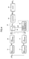
- FIG. 4 shows an embodiment of the invention, using the same reference numerals as in FIG. 3 for equivalent elements. Descriptions of these elements will be omitted.
- the quantizer 23 in FIG. 4 is equivalent to both the first and second quantizers 13 and 23 in FIG. 3.
- the main difference between the second example and the embodiment is that the quantized signal selector 34 of the second example is replaced in the embodiment by a transformed signal selector 44, which is disposed between the first and second scanners 12 and 22 and the quantizer 23.
- the transformed signal selector 44 comprises a switch 16 and an energy convergence comparator 45, which select one of the two one-dimensional signals s12 and s22 output by the first and second scanners 12 and 22, and supply the selected one-dimensional signal s16 to the quantizer 23.
- the energy convergence comparator 45 operates by comparing the rate of convergence of energy in the two one-dimensional signals s12 and s22. Specifically, the energy convergence comparator 45 arranges the transformed data in each one-dimensional signal in decreasing order of absolute value, then calculates a cumulative sum of squares in each one-dimensional signal and determines which sum converges more rapidly toward its final total value. A control signal s45 from the energy convergence comparator 45 commands the switch 16 to supply the one-dimensional signal with the faster energy convergence rate to the coder 24.
- the rate of energy convergence is a good indicator of the amount of non-zero data that will be present after quantization.
- the embodiment thus provides substantially the same effect as the second example, while requiring only one quantizer instead of two.
- the embodiment is advantageous when the same quantizing and coding methods and tables are employed for the transformed data resulting from both mathematical transformations.
- the number of mathematical transformations is not limited to two or three. In general N different mathematical transformations may be performed, and a selection made among the N resulting coded signals, where N is any number greater than unity.
- the embodiment can also be modified by increasing the number of mathematical transformations. Hybrid versions of these embodiments are furthermore possible. For example, a selection between first and second transformed signals can be made on the basis of energy convergence rate, and the selected signal can be quantized and coded by one method while a third transformed signal is being quantized and coded by another method; then the code sizes of the two coded signals can be compared and the smaller coded signal selected for output.
- the mathematical transformations need not all be two-dimensional block transformations. Some or all of the transformations may operate on the image as a whole, instead of on n x n blocks of pixels.
- control signals are output per larger units, e.g. one control signal per image.
- the invented image encoder need not comprise separate circuits as shown in the embodiment above.
- the various transform processors may be combined into a single processor that performs the necessary mathematical transformations one after another.
- This processor may also be adapted to carry out the scanning, quantizing, coding, and comparing operations performed by the other elements in the embodiments.
Description
- The present invention relates to an image encoder for encoding an image signal such as a digitized still-image signal or a differential image signal representing the difference between two frames in a moving image.
- Conventional image encoders begin by performing a two-dimensional mathematical transformation such as a discrete cosine transform or a wavelet transform on the image signal. The transformed data are next rearranged in a one-dimensional sequence and quantized according to a certain quantizing rule. The quantized data are then coded by a suitable method such as an entropy coding method. As a result, the input image signal is usually compressed to a fraction of its original size.
- One objective in image encoding is to achieve the maximum compression ratio. The key to attaining this objective is to have the mathematical transformation encode the image information in a relatively small number of non-zero values, or more precisely, in a relatively small number of values that will be quantized to non-zero values. Unfortunately, no single mathematical transformation works well for all images. Since the discrete cosine transform employs the cosine function, it succeeds excellently for image signals that vary in a periodic manner, but has less success with image signals in which sharp transitions (edges) appear at arbitrary locations. The wavelet transform is good at handling edges, but is less successful in dealing with periodic signals.
- Conventional image encoders thus yield high compression ratios for some image signals and low compression ratios for other image signals. As a result, the average compression ratio falls far short of the desired maximum.
- In FENG ZOU ET AL: "Maximum energy principle of multiple transforms in data compression", IEEE TRANSACTIONS ON SIGNAL PROCESSING, DEC. 1995, IEEE, USA, vol. 43, no. 12, ISSN 1053-587X, data compression with multiple transforms such as discrete cosine transform and wavelet transform to achieve a better data compression ratio is described.
- From EP 0 561 593, a picture data processing apparatus is known in which, even if an edge exists, deterioration of the picture quality is prevented. The picture data processing apparatus comprises a discrete cosine transform circuit and a wavelet transform circuit.
- It is accordingly an object of the present invention to improve the compression ratio of an image encoder.
- Another object is to encode different types of image signals with a high compression ratio.
- In the invented image encoding method according to
claim 1, an image signal is transformed by at least two different mathematical transformations to obtain at least two different transformed signals. These transformed signals are separately reordered to obtain respective one-dimensional signals. - The energy convergence rates of the one-dimensional signals are compared. The one-dimensional signal with the fastest energy convergence rate is selected, quantized, coded, and output. An image encoder according to the invention is set out in claim 3.
- In the attached drawings:
- FIG. 1 is a block diagram of a first example of a wavelet transform (WLT) device;
- FIG. 2 illustrates the output of a wavelet transform;
- FIG. 3 is a block diagram of a second example of a wavelet transform (WLT) device;
- FIG. 4 is a block diagram of an embodiment of the invention.
-
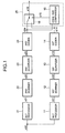
- Referring to FIG. 1, a typical wavelet transform (WLT) device comprises a wavelet transform (WLT)
processor 11, afirst scanner 12, afirst quantizer 13, afirst coder 14, acode size comparator 15, aswitch 16, a discrete cosine transform (DCT)processor 21, asecond scanner 22, asecond quantizer 23, and asecond coder 24. Thecode size comparator 15 andswitch 16 constitute a coded signal selector 25. These elements comprise well-known computational and memory circuits, detailed descriptions of which will be omitted to avoid obscuring the invention with irrelevant detail. The elements are interconnected as shown, and operate as follows. - An image signal s10 representing a two-dimensional image is input to the
wavelet transform processor 11 and discretecosine transform processor 21. Bothprocessors - The wavelet transform employs a low-pass filter h(k) and a high-pass filter g(k) having respective Fourier transforms H(ω) and G(ω) that satisfy the following conditions (ω is a variable representing frequency).
- The wavelet transform is carried out in successive stages, high-pass and low-pass spatial filtering being performed in each stage. The output of each stage comprises four components, representing different combinations of high and low horizontal and vertical spatial frequencies. If S(i-1)(j, k) and Si(j, k) denote the input and output of the i-th stage, additional subscripts H and L denote high and low, and an asterisk (*) denotes the mathematical convolution operation, the four components can be described by the following formulas.
- The notation (j/2, k/2) indicates that the output of each stage is scaled down by a factor of two in the horizontal and vertical directions. Equivalently, the cutoff frequency separating high-frequency components from low-frequency components is reduced by a factor of two in each stage. SLL0(j, k) is the input image signal s10.
- The wavelet transform is illustrated in FIG. 2 for the case of an 8 x 8 block. The symbol HL1, for example, denotes the data SHL1(j/2, k/2) given by the formula above. The result of this wavelet transform is a first transformed signal s11 comprising a two-dimensional array of sixty-four transformed data values for each 8 x 8 block of input image pixels. Each transformed data value is indicated by one block dot in FIG. 2.
- Each two-dimensional array is provided to the
first scanner 12, which reorders the data in the sequence shown in Table 1 to obtain a first one-dimensional signal s12.WLT Data Scanning Order 0 1 4 6 16 20 24 28 2 3 5 7 17 21 25 29 8 9 12 13 18 22 26 30 10 11 14 15 19 23 27 31 32 33 34 35 48 49 53 54 36 37 38 39 50 52 55 60 40 41 42 43 51 56 59 61 44 45 46 47 57 58 62 63 - The first one-dimensional signal s12 output by the
first scanner 12 is quantized by thefirst quantizer 13 to produce a first quantized signal s13. Quantization simply means that a range of possible signal values are mapped onto a single quantized value. The quantization rule can be described by a quantizing table stored in thefirst quantizer 13, or by one or more mathematical formulas. - The first quantized signal s14 is coded by the
first coder 14. The coding scheme employs, for example, variable-length codewords, each representing a run of zeros followed by one non-zero quantized value. A coding scheme of this type can be described in terms of a coding table. The resulting first coded signal s14 is output to the coded signal selector 25. - The discrete
cosine transform processor 21 transforms the same image signal s10 by the formula given below, which converts an n x n block of pixel values into an n x n block of coefficients F(u, v). The block-size parameter n is a positive integer such as eight.
- The resulting coefficients F(u, v) form a two-dimensional array, u denoting the horizontal dimension and v the vertical dimension. These two-dimensional arrays are output as a second transformed signal s21 to the
second scanner 22, which reorders the coefficients in the zig-zag sequence indicated by Table 2 to obtain a second one-dimensional signal s22.DCT Data Scanning Order 0 1 5 6 14 15 27 28 2 4 7 13 16 26 29 42 3 8 12 17 25 30 41 43 9 11 18 24 31 40 44 53 10 19 23 32 39 45 52 54 20 22 33 38 46 51 55 60 21 34 37 47 50 56 59 61 35 36 48 49 57 58 62 63 - The
second quantizer 23 quantizes the second one-dimensional signal s22 to obtain quantized coefficients QF(u, v). Thesecond quantizer 23 uses one pair of quantizing formulas for still images, and another pair of quantizing formulas for differential images. In a moving image, the first pair of formulas is used for intra-frames, and the second pair for inter-frames. Each pair of formulas has a parameter q denoting the quantization step size. The first pair of formulas, used for still images and intra-frames, is as follows. - The formulas used for differential images (inter-frames) are as follows.
- The quantized coefficient data QF(u, v) constitute the second quantized signal s23 output from the
second quantizer 23 to thesecond coder 24. Thesecond coder 24 codes this signal by a method similar to that employed in thefirst coder 14, for example, although not necessarily with the same coding table, and supplies the resulting second coded signal s24 to the coded signal selector 25. - In the coded signal selector 25, the
code size comparator 15 compares the total code size of the two coded signals s14 and s24, selects the coded signal with the smaller code size, and sends the switch 16 a control signal s15 commanding theswitch 16 to output the selected signal. In FIG. 1, the selected signal s16 is the second coded signal s24. - By using two different mathematical transformations and selecting the coded signal with the smaller code size, the first embodiment is able to obtain a high compression ratio for a wide variety of input image signals. The average compression performance of the first embodiment is thus considerably better than the compression performance of an image coder of the conventional type, which is limited to a single mathematical transformation.
- The use of
independent quantizers independent coders second coders - FIG. 3 shows a second example of the wavelet transform (WLT) device using the same reference numerals as in FIG. 1 for equivalent elements. Descriptions of these elements will be omitted. The
coder 24 in FIG. 3 is equivalent to both the first andsecond coders - The main difference between the first and second examples is that the coded signal selector 25 of the first example is replaced in the second example by a
quantized signal selector 34, which is disposed between the first and second quantizers 13 and 23 and thecoder 24. Thequantized signal selector 34 comprises aswitch 16 and aquantized data comparator 35, which select one of the two quantized signals s13 and s23 output by the first and second quantizers 13 and 23, and supply the selected quantized signal s16 to thecoder 24. - The quantized
data comparator 35 operates by counting the number of non-zero data values in the first and second quantized signals s13 and s23, and selecting the quantized signal with the least amount of non-zero data. A control signal s35 from the quantizeddata comparator 35 commands theswitch 16 to supply the selected quantized signal to thecoder 24. - The other elements in the second example operate as in the first example.
- The amount of non-zero data in the quantized signals predicts the size of the coded data with good accuracy, so the second example provides substantially the same effect as the first example, while requiring only one coder instead of two. The second example is advantageous when the same coding method and coding table are employed for the quantized data resulting from both mathematical transformations.
- FIG. 4 shows an embodiment of the invention, using the same reference numerals as in FIG. 3 for equivalent elements. Descriptions of these elements will be omitted. The
quantizer 23 in FIG. 4 is equivalent to both the first and second quantizers 13 and 23 in FIG. 3. - The main difference between the second example and the embodiment is that the
quantized signal selector 34 of the second example is replaced in the embodiment by a transformedsignal selector 44, which is disposed between the first andsecond scanners quantizer 23. The transformedsignal selector 44 comprises aswitch 16 and anenergy convergence comparator 45, which select one of the two one-dimensional signals s12 and s22 output by the first andsecond scanners quantizer 23. - The
energy convergence comparator 45 operates by comparing the rate of convergence of energy in the two one-dimensional signals s12 and s22. Specifically, theenergy convergence comparator 45 arranges the transformed data in each one-dimensional signal in decreasing order of absolute value, then calculates a cumulative sum of squares in each one-dimensional signal and determines which sum converges more rapidly toward its final total value. A control signal s45 from theenergy convergence comparator 45 commands theswitch 16 to supply the one-dimensional signal with the faster energy convergence rate to thecoder 24. - The other elements in the embodiment operate as in the second example.
- The rate of energy convergence is a good indicator of the amount of non-zero data that will be present after quantization. The embodiment thus provides substantially the same effect as the second example, while requiring only one quantizer instead of two. The embodiment is advantageous when the same quantizing and coding methods and tables are employed for the transformed data resulting from both mathematical transformations.
- The number of mathematical transformations is not limited to two or three. In general N different mathematical transformations may be performed, and a selection made among the N resulting coded signals, where N is any number greater than unity.
- The embodiment can also be modified by increasing the number of mathematical transformations. Hybrid versions of these embodiments are furthermore possible. For example, a selection between first and second transformed signals can be made on the basis of energy convergence rate, and the selected signal can be quantized and coded by one method while a third transformed signal is being quantized and coded by another method; then the code sizes of the two coded signals can be compared and the smaller coded signal selected for output.
- The mathematical transformations need not all be two-dimensional block transformations. Some or all of the transformations may operate on the image as a whole, instead of on n x n blocks of pixels.
- If the mathematical transformations are all two-dimensional block transformations, however, and if the block sizes are all the same, the code size comparator, quantized data comparator, or energy convergence comparator can generate a separate control signal for each block. In other cases, control signals are output per larger units, e.g. one control signal per image.
- The invented image encoder need not comprise separate circuits as shown in the embodiment above. The various transform processors, for example, may be combined into a single processor that performs the necessary mathematical transformations one after another. This processor may also be adapted to carry out the scanning, quantizing, coding, and comparing operations performed by the other elements in the embodiments.
- Those skilled in the art will recognize that further modifications are possible.
Claims (7)
- A method of encoding an image signal, comprising the steps of:wherein said step of selecting, quantizing, and coding comprises the further steps of:performing a plurality of different mathematical transformations on said image signal, thereby obtaining a plurality of transformed signals;reordering said transformed signals to obtain respective one-dimensional signals;selecting, quantizing, and coding one of said one-dimensional signals to obtain a coded signal, and outputting said coded signalscomparing energy convergence rates of said one-dimensional signals; andselecting from among said one-dimensional signals a one-dimensional signal with a fastest energy convergence rate.
- The method of claim 1, wherein said step of comparing energy convergence rates comprises the further steps of:calculating cumulative sums of squares in respective one-dimensional signals; andcomparing said cumulative sums of squares.
- An image encoder for encoding an image signal, comprising:a plurality of transform processors (11, 21) for performing different mathematical transformations on said image signal in parallel, thereby obtaining a plurality of transformed signals;a like plurality of scanners (12, 22) coupled to respective transform processors, for reordering said transformed signals to obtain respective one-dimensional signals;a transformed signal selector (44) coupled to said scanners, for comparing rates of convergence of energy in said one-dimensional signals, and selecting a one-dimensional signal with a fastest rate of convergence of energy;a quantizer (23) coupled to said transformed signal selector, for quantizing the one-dimensional signal selected by said transformed signal selector to obtain a quantized signal; anda coder (24) coupled to said quantizer, for coding said quantized signal to obtain a coded signal, and outputting said coded signal.
- The image encoder of claim 3, wherein said transformed signal selector (44) compares cumulative sums of squares of said one-dimensional signals.
- The image encoder of claim 3, wherein said transform processors (11, 21) divide said image signal into blocks and perform two-dimensional mathematical transformations on said blocks.
- The image encoder of claim 5, wherein one of said transform processors (11) performs a wavelet transform.
- The image encoder of claim 6, wherein another one of said transform processors (21) performs a discrete cosine transform.
Priority Applications (2)
| Application Number | Priority Date | Filing Date | Title |
|---|---|---|---|
| EP20010103268 EP1102490B1 (en) | 1996-03-22 | 1997-02-19 | Image encoding method and image encoder |
| EP20010103269 EP1102491A1 (en) | 1996-03-22 | 1997-02-19 | Image encoding method and image encoder |
Applications Claiming Priority (3)
| Application Number | Priority Date | Filing Date | Title |
|---|---|---|---|
| JP6604796A JPH09261640A (en) | 1996-03-22 | 1996-03-22 | Image coder |
| JP66047/96 | 1996-03-22 | ||
| JP6604796 | 1996-03-22 |
Related Child Applications (2)
| Application Number | Title | Priority Date | Filing Date |
|---|---|---|---|
| EP20010103269 Division EP1102491A1 (en) | 1996-03-22 | 1997-02-19 | Image encoding method and image encoder |
| EP20010103268 Division EP1102490B1 (en) | 1996-03-22 | 1997-02-19 | Image encoding method and image encoder |
Publications (3)
| Publication Number | Publication Date |
|---|---|
| EP0797356A2 EP0797356A2 (en) | 1997-09-24 |
| EP0797356A3 EP0797356A3 (en) | 1997-12-29 |
| EP0797356B1 true EP0797356B1 (en) | 2002-05-15 |
Family
ID=13304580
Family Applications (3)
| Application Number | Title | Priority Date | Filing Date |
|---|---|---|---|
| EP20010103268 Expired - Lifetime EP1102490B1 (en) | 1996-03-22 | 1997-02-19 | Image encoding method and image encoder |
| EP20010103269 Withdrawn EP1102491A1 (en) | 1996-03-22 | 1997-02-19 | Image encoding method and image encoder |
| EP19970102665 Expired - Lifetime EP0797356B1 (en) | 1996-03-22 | 1997-02-19 | Image encoding method and image encoder |
Family Applications Before (2)
| Application Number | Title | Priority Date | Filing Date |
|---|---|---|---|
| EP20010103268 Expired - Lifetime EP1102490B1 (en) | 1996-03-22 | 1997-02-19 | Image encoding method and image encoder |
| EP20010103269 Withdrawn EP1102491A1 (en) | 1996-03-22 | 1997-02-19 | Image encoding method and image encoder |
Country Status (4)
| Country | Link |
|---|---|
| US (1) | US5953460A (en) |
| EP (3) | EP1102490B1 (en) |
| JP (1) | JPH09261640A (en) |
| DE (2) | DE69712566T2 (en) |
Families Citing this family (24)
| Publication number | Priority date | Publication date | Assignee | Title |
|---|---|---|---|---|
| US6359928B1 (en) * | 1997-09-29 | 2002-03-19 | University Of Southern California | System and method for compressing images using multi-threshold wavelet coding |
| US6389169B1 (en) * | 1998-06-08 | 2002-05-14 | Lawrence W. Stark | Intelligent systems and methods for processing image data based upon anticipated regions of visual interest |
| JP2000069292A (en) * | 1998-08-24 | 2000-03-03 | Canon Inc | Image processing unit, its method and storage medium |
| US6587505B1 (en) * | 1998-08-31 | 2003-07-01 | Canon Kabushiki Kaisha | Image processing apparatus and method |
| JP3285331B2 (en) * | 1999-04-12 | 2002-05-27 | オリンパス光学工業株式会社 | Image recording device and electronic camera device |
| US6831946B1 (en) * | 1999-11-08 | 2004-12-14 | Lg Electronics Inc. | Device and method for coding image |
| GB2356510B (en) * | 1999-11-18 | 2004-04-21 | Sony Uk Ltd | Data compression |
| GB2364843A (en) * | 2000-07-14 | 2002-02-06 | Sony Uk Ltd | Data encoding based on data quantity and data quality |
| JP4607305B2 (en) | 2000-09-27 | 2011-01-05 | 株式会社東芝 | Video encoding apparatus and video encoding method |
| US6947486B2 (en) * | 2001-03-23 | 2005-09-20 | Visioprime | Method and system for a highly efficient low bit rate video codec |
| JP2003006643A (en) * | 2001-06-25 | 2003-01-10 | Canon Inc | Device and method for processing image and program |
| WO2003026308A2 (en) * | 2001-09-14 | 2003-03-27 | Siemens Aktiengesellschaft | Method and device for enhancing coding/decoding of video signals |
| JP4447197B2 (en) * | 2002-01-07 | 2010-04-07 | 三菱電機株式会社 | Moving picture encoding apparatus and moving picture decoding apparatus |
| KR100472442B1 (en) * | 2002-02-16 | 2005-03-08 | 삼성전자주식회사 | Method for compressing audio signal using wavelet packet transform and apparatus thereof |
| JP3783956B2 (en) | 2002-07-23 | 2006-06-07 | 株式会社リコー | Image recording apparatus and image data selection method |
| US7162104B2 (en) * | 2002-08-30 | 2007-01-09 | W.W. Grainger, Inc. | System and method for image compression, storage, and retrieval |
| US7720999B2 (en) * | 2002-11-26 | 2010-05-18 | Qualcomm Incorporated | System and method for optimizing multimedia compression using plural encoders |
| JP4640382B2 (en) * | 2007-06-25 | 2011-03-02 | ブラザー工業株式会社 | Data file compression apparatus, program, and data file compression method |
| KR100898058B1 (en) * | 2007-07-09 | 2009-05-19 | 중앙대학교 산학협력단 | Apparatus and method for transforming between discrete cosine transform coefficient and cosine transform coefficient |
| US20090060039A1 (en) * | 2007-09-05 | 2009-03-05 | Yasuharu Tanaka | Method and apparatus for compression-encoding moving image |
| US8297818B2 (en) * | 2009-06-11 | 2012-10-30 | Rambus International Ltd. | Optical system with reflectors and light pipes |
| WO2011010959A1 (en) * | 2009-07-23 | 2011-01-27 | Telefonaktiebolaget L M Ericsson (Publ) | Method and apparatus for encoding and decoding of images |
| US20140328406A1 (en) | 2013-05-01 | 2014-11-06 | Raymond John Westwater | Method and Apparatus to Perform Optimal Visually-Weighed Quantization of Time-Varying Visual Sequences in Transform Space |
| TWI726822B (en) | 2019-10-08 | 2021-05-01 | 創未來科技股份有限公司 | Signal converting apparatus |
Family Cites Families (12)
| Publication number | Priority date | Publication date | Assignee | Title |
|---|---|---|---|---|
| EP0207774B1 (en) * | 1985-07-02 | 1992-03-04 | Matsushita Electric Industrial Co., Ltd. | Block encoder |
| JPH0398318A (en) * | 1989-09-11 | 1991-04-23 | Fujitsu Ltd | Voice coding system |
| US5063608A (en) * | 1989-11-03 | 1991-11-05 | Datacube Inc. | Adaptive zonal coder |
| DE4004857A1 (en) * | 1990-02-16 | 1991-09-12 | Bosch Gmbh Robert | Bandwidth reduction video signal coding systems - uses low and high pass filtering to divide signal into partial bands for different data reduction |
| US5068724A (en) * | 1990-06-15 | 1991-11-26 | General Instrument Corporation | Adaptive motion compensation for digital television |
| DE69312132T2 (en) * | 1992-03-17 | 1998-01-15 | Sony Corp | Image compression device |
| EP0607484B1 (en) * | 1993-01-20 | 1998-09-09 | Samsung Electronics Co. Ltd. | Method and device for encoding and decoding image data |
| US5412741A (en) * | 1993-01-22 | 1995-05-02 | David Sarnoff Research Center, Inc. | Apparatus and method for compressing information |
| JP2933457B2 (en) * | 1993-02-18 | 1999-08-16 | 日本電気株式会社 | Wavelet transform coding method |
| JP3163880B2 (en) * | 1993-12-16 | 2001-05-08 | 松下電器産業株式会社 | Image compression coding device |
| JP3954656B2 (en) * | 1994-09-29 | 2007-08-08 | ソニー株式会社 | Image coding apparatus and method |
| KR0159434B1 (en) * | 1995-04-19 | 1999-01-15 | 김광호 | Wavelet image encoding and decoding device and method using human visual system modeling |
-
1996
- 1996-03-22 JP JP6604796A patent/JPH09261640A/en active Pending
-
1997
- 1997-02-19 EP EP20010103268 patent/EP1102490B1/en not_active Expired - Lifetime
- 1997-02-19 EP EP20010103269 patent/EP1102491A1/en not_active Withdrawn
- 1997-02-19 DE DE1997612566 patent/DE69712566T2/en not_active Expired - Lifetime
- 1997-02-19 DE DE1997621850 patent/DE69721850T2/en not_active Expired - Lifetime
- 1997-02-19 EP EP19970102665 patent/EP0797356B1/en not_active Expired - Lifetime
- 1997-02-21 US US08/804,514 patent/US5953460A/en not_active Expired - Lifetime
Also Published As
| Publication number | Publication date |
|---|---|
| DE69721850T2 (en) | 2004-02-26 |
| DE69712566T2 (en) | 2002-12-19 |
| EP0797356A3 (en) | 1997-12-29 |
| EP0797356A2 (en) | 1997-09-24 |
| JPH09261640A (en) | 1997-10-03 |
| EP1102490A1 (en) | 2001-05-23 |
| DE69721850D1 (en) | 2003-06-12 |
| EP1102490B1 (en) | 2003-05-07 |
| DE69712566D1 (en) | 2002-06-20 |
| US5953460A (en) | 1999-09-14 |
| EP1102491A1 (en) | 2001-05-23 |
Similar Documents
| Publication | Publication Date | Title |
|---|---|---|
| EP0797356B1 (en) | Image encoding method and image encoder | |
| US20180343456A1 (en) | System and method for using pattern vectors for video and image coding and decoding | |
| US6359928B1 (en) | System and method for compressing images using multi-threshold wavelet coding | |
| US7336720B2 (en) | Real-time video coding/decoding | |
| US5812788A (en) | Encoding/decoding video signals using quantization tables based on explicitly encoded base and scale matrices | |
| KR100914160B1 (en) | Lossless intraframe encoding using golomb-rice | |
| US6665444B1 (en) | Image processing apparatus and method, and storage medium | |
| US5949912A (en) | Image coding method and apparatus | |
| EP1571849A2 (en) | Curved wavelet transform for image and video compression | |
| WO2001006794A1 (en) | Encoding method for the compression of a video sequence | |
| US5719961A (en) | Adaptive technique for encoder and decoder signal transformation | |
| US7065252B1 (en) | System and method providing improved data compression via wavelet coefficient encoding | |
| US5822000A (en) | Video encoding using rearrangement of transform coefficients and inter-block correlation | |
| JP3163880B2 (en) | Image compression coding device | |
| US20040006582A1 (en) | Digital image coding device and method | |
| US5724096A (en) | Video signal encoding method and apparatus employing inter-block redundancies | |
| Messaoudi | DCT-based compression algorithm using reduced adaptive block scanning for color image | |
| Bauermann et al. | Further lossless compression of Jpeg Images | |
| JP2841197B2 (en) | Method of compressing gradation image data | |
| Ranjeeta et al. | Image compression: an overview | |
| US20040105590A1 (en) | Method for still image compressing using filter bank based on non-separable wavelet basis | |
| JP3205028B2 (en) | Image compression apparatus and method | |
| JPH10327405A (en) | Image encoding/decoding device and method therefor | |
| JP3232160B2 (en) | Encoding device and method | |
| Xu et al. | Eliminating blocking artifacts in halftoning-based block truncation coding |
Legal Events
| Date | Code | Title | Description |
|---|---|---|---|
| PUAI | Public reference made under article 153(3) epc to a published international application that has entered the european phase |
Free format text: ORIGINAL CODE: 0009012 |
|
| AK | Designated contracting states |
Kind code of ref document: A2 Designated state(s): DE FR GB |
|
| PUAL | Search report despatched |
Free format text: ORIGINAL CODE: 0009013 |
|
| AK | Designated contracting states |
Kind code of ref document: A3 Designated state(s): DE FR GB |
|
| 17P | Request for examination filed |
Effective date: 19980629 |
|
| 17Q | First examination report despatched |
Effective date: 20001018 |
|
| GRAG | Despatch of communication of intention to grant |
Free format text: ORIGINAL CODE: EPIDOS AGRA |
|
| GRAG | Despatch of communication of intention to grant |
Free format text: ORIGINAL CODE: EPIDOS AGRA |
|
| GRAG | Despatch of communication of intention to grant |
Free format text: ORIGINAL CODE: EPIDOS AGRA |
|
| GRAH | Despatch of communication of intention to grant a patent |
Free format text: ORIGINAL CODE: EPIDOS IGRA |
|
| GRAH | Despatch of communication of intention to grant a patent |
Free format text: ORIGINAL CODE: EPIDOS IGRA |
|
| GRAA | (expected) grant |
Free format text: ORIGINAL CODE: 0009210 |
|
| AK | Designated contracting states |
Kind code of ref document: B1 Designated state(s): DE FR GB |
|
| REG | Reference to a national code |
Ref country code: GB Ref legal event code: FG4D |
|
| REF | Corresponds to: |
Ref document number: 69712566 Country of ref document: DE Date of ref document: 20020620 |
|
| ET | Fr: translation filed | ||
| PLBE | No opposition filed within time limit |
Free format text: ORIGINAL CODE: 0009261 |
|
| STAA | Information on the status of an ep patent application or granted ep patent |
Free format text: STATUS: NO OPPOSITION FILED WITHIN TIME LIMIT |
|
| 26N | No opposition filed |
Effective date: 20030218 |
|
| PGFP | Annual fee paid to national office [announced via postgrant information from national office to epo] |
Ref country code: FR Payment date: 20130301 Year of fee payment: 17 Ref country code: DE Payment date: 20130213 Year of fee payment: 17 Ref country code: GB Payment date: 20130213 Year of fee payment: 17 |
|
| REG | Reference to a national code |
Ref country code: DE Ref legal event code: R119 Ref document number: 69712566 Country of ref document: DE |
|
| GBPC | Gb: european patent ceased through non-payment of renewal fee |
Effective date: 20140219 |
|
| REG | Reference to a national code |
Ref country code: FR Ref legal event code: ST Effective date: 20141031 |
|
| REG | Reference to a national code |
Ref country code: DE Ref legal event code: R119 Ref document number: 69712566 Country of ref document: DE Effective date: 20140902 |
|
| PG25 | Lapsed in a contracting state [announced via postgrant information from national office to epo] |
Ref country code: GB Free format text: LAPSE BECAUSE OF NON-PAYMENT OF DUE FEES Effective date: 20140219 Ref country code: DE Free format text: LAPSE BECAUSE OF NON-PAYMENT OF DUE FEES Effective date: 20140902 Ref country code: FR Free format text: LAPSE BECAUSE OF NON-PAYMENT OF DUE FEES Effective date: 20140228 |