EP0795404A2 - Ink jet recording head - Google Patents
Ink jet recording head Download PDFInfo
- Publication number
- EP0795404A2 EP0795404A2 EP97108517A EP97108517A EP0795404A2 EP 0795404 A2 EP0795404 A2 EP 0795404A2 EP 97108517 A EP97108517 A EP 97108517A EP 97108517 A EP97108517 A EP 97108517A EP 0795404 A2 EP0795404 A2 EP 0795404A2
- Authority
- EP
- European Patent Office
- Prior art keywords
- flow passage
- ink
- recording head
- jet recording
- piezoelectric
- Prior art date
- Legal status (The legal status is an assumption and is not a legal conclusion. Google has not performed a legal analysis and makes no representation as to the accuracy of the status listed.)
- Granted
Links
- 239000000758 substrate Substances 0.000 claims abstract description 40
- 238000006073 displacement reaction Methods 0.000 claims abstract description 12
- 239000000853 adhesive Substances 0.000 description 7
- 230000001070 adhesive effect Effects 0.000 description 7
- 238000000034 method Methods 0.000 description 7
- 239000010408 film Substances 0.000 description 5
- 229920006332 epoxy adhesive Polymers 0.000 description 3
- 239000000463 material Substances 0.000 description 3
- PXHVJJICTQNCMI-UHFFFAOYSA-N Nickel Chemical compound [Ni] PXHVJJICTQNCMI-UHFFFAOYSA-N 0.000 description 2
- 238000003491 array Methods 0.000 description 2
- 239000000919 ceramic Substances 0.000 description 2
- 239000003822 epoxy resin Substances 0.000 description 2
- 239000012530 fluid Substances 0.000 description 2
- 238000007641 inkjet printing Methods 0.000 description 2
- 238000004519 manufacturing process Methods 0.000 description 2
- 229920000647 polyepoxide Polymers 0.000 description 2
- 229920005989 resin Polymers 0.000 description 2
- 239000011347 resin Substances 0.000 description 2
- 238000003848 UV Light-Curing Methods 0.000 description 1
- 230000003247 decreasing effect Effects 0.000 description 1
- 230000001419 dependent effect Effects 0.000 description 1
- 238000005323 electroforming Methods 0.000 description 1
- 230000002708 enhancing effect Effects 0.000 description 1
- 238000003780 insertion Methods 0.000 description 1
- 230000037431 insertion Effects 0.000 description 1
- 238000002955 isolation Methods 0.000 description 1
- 239000002184 metal Substances 0.000 description 1
- 229910052751 metal Inorganic materials 0.000 description 1
- 229910052759 nickel Inorganic materials 0.000 description 1
- 238000005192 partition Methods 0.000 description 1
- 230000002093 peripheral effect Effects 0.000 description 1
- 238000007747 plating Methods 0.000 description 1
- 239000000047 product Substances 0.000 description 1
- 239000013589 supplement Substances 0.000 description 1
- 239000010409 thin film Substances 0.000 description 1
Images


Classifications
-
- B—PERFORMING OPERATIONS; TRANSPORTING
- B41—PRINTING; LINING MACHINES; TYPEWRITERS; STAMPS
- B41J—TYPEWRITERS; SELECTIVE PRINTING MECHANISMS, i.e. MECHANISMS PRINTING OTHERWISE THAN FROM A FORME; CORRECTION OF TYPOGRAPHICAL ERRORS
- B41J2/00—Typewriters or selective printing mechanisms characterised by the printing or marking process for which they are designed
- B41J2/005—Typewriters or selective printing mechanisms characterised by the printing or marking process for which they are designed characterised by bringing liquid or particles selectively into contact with a printing material
- B41J2/01—Ink jet
- B41J2/135—Nozzles
- B41J2/16—Production of nozzles
- B41J2/1621—Manufacturing processes
- B41J2/1625—Manufacturing processes electroforming
-
- B—PERFORMING OPERATIONS; TRANSPORTING
- B41—PRINTING; LINING MACHINES; TYPEWRITERS; STAMPS
- B41J—TYPEWRITERS; SELECTIVE PRINTING MECHANISMS, i.e. MECHANISMS PRINTING OTHERWISE THAN FROM A FORME; CORRECTION OF TYPOGRAPHICAL ERRORS
- B41J2/00—Typewriters or selective printing mechanisms characterised by the printing or marking process for which they are designed
- B41J2/005—Typewriters or selective printing mechanisms characterised by the printing or marking process for which they are designed characterised by bringing liquid or particles selectively into contact with a printing material
- B41J2/01—Ink jet
- B41J2/135—Nozzles
- B41J2/14—Structure thereof only for on-demand ink jet heads
- B41J2/14201—Structure of print heads with piezoelectric elements
- B41J2/14274—Structure of print heads with piezoelectric elements of stacked structure type, deformed by compression/extension and disposed on a diaphragm
-
- B—PERFORMING OPERATIONS; TRANSPORTING
- B41—PRINTING; LINING MACHINES; TYPEWRITERS; STAMPS
- B41J—TYPEWRITERS; SELECTIVE PRINTING MECHANISMS, i.e. MECHANISMS PRINTING OTHERWISE THAN FROM A FORME; CORRECTION OF TYPOGRAPHICAL ERRORS
- B41J2/00—Typewriters or selective printing mechanisms characterised by the printing or marking process for which they are designed
- B41J2/005—Typewriters or selective printing mechanisms characterised by the printing or marking process for which they are designed characterised by bringing liquid or particles selectively into contact with a printing material
- B41J2/01—Ink jet
- B41J2/135—Nozzles
- B41J2/16—Production of nozzles
- B41J2/1607—Production of print heads with piezoelectric elements
- B41J2/1612—Production of print heads with piezoelectric elements of stacked structure type, deformed by compression/extension and disposed on a diaphragm
-
- B—PERFORMING OPERATIONS; TRANSPORTING
- B41—PRINTING; LINING MACHINES; TYPEWRITERS; STAMPS
- B41J—TYPEWRITERS; SELECTIVE PRINTING MECHANISMS, i.e. MECHANISMS PRINTING OTHERWISE THAN FROM A FORME; CORRECTION OF TYPOGRAPHICAL ERRORS
- B41J2/00—Typewriters or selective printing mechanisms characterised by the printing or marking process for which they are designed
- B41J2/005—Typewriters or selective printing mechanisms characterised by the printing or marking process for which they are designed characterised by bringing liquid or particles selectively into contact with a printing material
- B41J2/01—Ink jet
- B41J2/135—Nozzles
- B41J2/16—Production of nozzles
- B41J2/1607—Production of print heads with piezoelectric elements
- B41J2/1618—Fixing the piezoelectric elements
-
- B—PERFORMING OPERATIONS; TRANSPORTING
- B41—PRINTING; LINING MACHINES; TYPEWRITERS; STAMPS
- B41J—TYPEWRITERS; SELECTIVE PRINTING MECHANISMS, i.e. MECHANISMS PRINTING OTHERWISE THAN FROM A FORME; CORRECTION OF TYPOGRAPHICAL ERRORS
- B41J2/00—Typewriters or selective printing mechanisms characterised by the printing or marking process for which they are designed
- B41J2/005—Typewriters or selective printing mechanisms characterised by the printing or marking process for which they are designed characterised by bringing liquid or particles selectively into contact with a printing material
- B41J2/01—Ink jet
- B41J2/135—Nozzles
- B41J2/16—Production of nozzles
- B41J2/1621—Manufacturing processes
- B41J2/1623—Manufacturing processes bonding and adhesion
-
- B—PERFORMING OPERATIONS; TRANSPORTING
- B41—PRINTING; LINING MACHINES; TYPEWRITERS; STAMPS
- B41J—TYPEWRITERS; SELECTIVE PRINTING MECHANISMS, i.e. MECHANISMS PRINTING OTHERWISE THAN FROM A FORME; CORRECTION OF TYPOGRAPHICAL ERRORS
- B41J2/00—Typewriters or selective printing mechanisms characterised by the printing or marking process for which they are designed
- B41J2/005—Typewriters or selective printing mechanisms characterised by the printing or marking process for which they are designed characterised by bringing liquid or particles selectively into contact with a printing material
- B41J2/01—Ink jet
- B41J2/135—Nozzles
- B41J2/16—Production of nozzles
- B41J2/1621—Manufacturing processes
- B41J2/1632—Manufacturing processes machining
-
- B—PERFORMING OPERATIONS; TRANSPORTING
- B41—PRINTING; LINING MACHINES; TYPEWRITERS; STAMPS
- B41J—TYPEWRITERS; SELECTIVE PRINTING MECHANISMS, i.e. MECHANISMS PRINTING OTHERWISE THAN FROM A FORME; CORRECTION OF TYPOGRAPHICAL ERRORS
- B41J2/00—Typewriters or selective printing mechanisms characterised by the printing or marking process for which they are designed
- B41J2/005—Typewriters or selective printing mechanisms characterised by the printing or marking process for which they are designed characterised by bringing liquid or particles selectively into contact with a printing material
- B41J2/01—Ink jet
- B41J2/135—Nozzles
- B41J2/16—Production of nozzles
- B41J2/1621—Manufacturing processes
- B41J2/164—Manufacturing processes thin film formation
- B41J2/1643—Manufacturing processes thin film formation thin film formation by plating
-
- B—PERFORMING OPERATIONS; TRANSPORTING
- B41—PRINTING; LINING MACHINES; TYPEWRITERS; STAMPS
- B41J—TYPEWRITERS; SELECTIVE PRINTING MECHANISMS, i.e. MECHANISMS PRINTING OTHERWISE THAN FROM A FORME; CORRECTION OF TYPOGRAPHICAL ERRORS
- B41J2/00—Typewriters or selective printing mechanisms characterised by the printing or marking process for which they are designed
- B41J2/005—Typewriters or selective printing mechanisms characterised by the printing or marking process for which they are designed characterised by bringing liquid or particles selectively into contact with a printing material
- B41J2/01—Ink jet
- B41J2/135—Nozzles
- B41J2/14—Structure thereof only for on-demand ink jet heads
- B41J2002/14387—Front shooter
-
- Y—GENERAL TAGGING OF NEW TECHNOLOGICAL DEVELOPMENTS; GENERAL TAGGING OF CROSS-SECTIONAL TECHNOLOGIES SPANNING OVER SEVERAL SECTIONS OF THE IPC; TECHNICAL SUBJECTS COVERED BY FORMER USPC CROSS-REFERENCE ART COLLECTIONS [XRACs] AND DIGESTS
- Y10—TECHNICAL SUBJECTS COVERED BY FORMER USPC
- Y10T—TECHNICAL SUBJECTS COVERED BY FORMER US CLASSIFICATION
- Y10T29/00—Metal working
- Y10T29/49—Method of mechanical manufacture
- Y10T29/49401—Fluid pattern dispersing device making, e.g., ink jet
Definitions
- the present invention relates to an ink jet recording head wherein the movement of a piezoelectric element moves part of an ink flow passage substrate so as to jet out ink stored therein in the form of ink droplets.
- an ink jet recording head employing a piezoelectric vibrator which moves in the longitudinal direction to apply pressure to ink stored within a pressure chamber, and the pressurized ink is then jetted out from a nozzle as droplets of ink onto a recording medium.
- the piezoelectric vibrators In the recording head of the above-mentioned type, a large number of piezoelectric vibrators are inserted into guide holes formed in the upper and lower portions of a support member to thereby position and support the respective base end portions and leading end portions thereof.
- the piezoelectric vibrators cannot be disposed in a high density arrangement. Also, they may be unevenly in the longitudinal direction thereof, and may be inclined with respect to each other, which makes it impossible to provide a uniform ink jet characteristic.
- Document EP-A-0 126 649 discloses a fluid jet print head that includes a manifold which defines an elongated cavity, and an orifice plate defining a plurality of orifices.
- a piezoelectric means is mounted in the cavity and spaced from the orifice plate to define a fluid reservoir therebetween.
- the transducer arrangement also includes acoustic isolation material such that unwanted wave propagation along the transducer is prevented.
- Document JP-A-32 34 538 discloses a method for producing an ink jet recording head in which a plurality of ink chambers are formed by inserting a plurality of teeth of a piezoelectric actuator into a plurality of grooves that are etched into a substrate. The transducer thus produced is formed with a minimal number of assembly steps.
- the invention provides an ink jet recording head for use in an ink jet recording device which ejects drops of ink to thereby form an image and, more particularly, an ink jet recording head having a mechanism for precisely positioning the respective components of the head.
- the piezoelectric element is divided into a plurality of piezoelectric vibrators, and piezoelectric vibrators are held and positioned in the surface direction thereof by a holding device.
- the outermost piezoelectric vibrators are used as vibrator-positioning members to thereby enhance the working accuracy of the remaining vibrators used for ink jetting.
- the vibrator-positioning member vibrators are used for positioning the vibrators with respect to the holding device or an ink flow passage substrate.
- a pressure chamber in a flow passage substrate is formed in such a manner that both side portions thererof respectively have a plane, and the vibrator-positioning members are respectively opposite to these planar side portions of the ink flow passage substrate, thereby enhancing the positioning accuracy between the ink flow passage forming substrate and the piezoelectric vibrators in the displacement direction thereof.
- positioning projections respectively provided on both sides of the fixing plate, which serve as a positioning reference for the piezoelectric vibrators, are used as the positioning portions that position the ink flow passage substrate in the surface direction thereof, so that the piezoelectric vibrators and the ink flow passage substrate can be positioned directly.
- Figs. 1 and 2 illustrate an ink jet recording head according to a first embodiment of the invention.
- the ink jet recording head includes a plate-shaped lamination-type piezoelectric element 1 which, as will be described later, is cut into rectangular pieces which are mounted on a fixing plate 2 to provide a large number of vibrators 11.
- a holding frame 3 holds the vibrators 11 and positions them in the surface direction of a cavity unit 5.
- the cavity unit 5 is positioned and held onto the holding frame 3 by a positioning pin 34.
- Reference numeral 38 denotes a cover which supports the outer peripheral portion of the cavity unit 5.
- Reference numerals 28 and 29 designates a lead frame; and reference numeral 9 indicates a head circuit board.
- Figs. 3(a) to 3(d) and 4 illustrate the piezoelectric element 1 and fixing plate 2.
- the fixing plate 2 is formed of free-cutting ceramics or the like, and includes an electrode 24 on the top surface thereof.
- the fixing plate 2 is substantially of a U-shape having positioning portions 22 protruded from both ends thereof.
- the plate-shaped piezoelectric element 1 has an electrode 14 on the lower surface and the rear end face thereof (see Fig. 4).
- the piezoelectric element 1 is firmly adhered to the fixing plate 2 in such a manner that the leading edge of the piezoelectric element 1 is protruded from an edge 23 by a given length for keeping an active length L constant, and also the electrode 14 on the lower surface of the element 1 are in contact with the electrode 24 of the fixing plate 2.
- the piezoelectric element 1 is formed to have a width which is greater than the length of a corresponding nozzle array. After it is fixed to the fixing plate 2, the piezoelectric element 1 is sliced into a plurality of vibrators 11, and two vibrator-positioning members 12 each pitch between vibrators having a width corresponding to the pitch of a nozzle 61 (see Fig. 6), by use of a slicing machine such as a wire saw or the like (see Fig. 3(c)). In this case, two rectangular parts respectively formed on the two outermost sides of these vibrators 11 are used as vibrator-positioning members 12. The vibrator positioning members 12 serve to absorb any deformation of the two side ends of the vibrators which occurs during the slicing operation, and to protect the thin vibrators 11.
- the signal electrodes 25 are connected to respective lead wires 29, and the lead wires 29 are connected to the head circuit board 9 (see Fig. 1).
- two common electrodes 26 are respectively connected to the lead frames 28 which extend to the head circuit board 9.
- a thin conductive film such as flexible cable or metal plate is electrically attached electrode 15 of each vibrators 11 and both ends of film 27 is connected to the common electrodes 26.
- the holding frame 3 which positions and holds the vibrators 11 and the fixing plate 2 is formed of an epoxy resin or other material in a cylindrical shape having a skirt like portion 31 which fans out at the bottom.
- reference numeral 36 designates an inclined guide surface which is formed so as to taper toward the positioning hole 33 so as to facilitate the insertion of the piezoelectric element 1.
- the holding frame 3, which holds the piezoelectric element 1 and the fixing plate 2 has a positioning hole 33 on the top surface 32 (see Figs. 1 and 5).
- the positioning hole 33 includes a wide portion 33a into which the fixing plate 2 can be fitted with a slight clearance ⁇ 1 in the thickness direction thereof, and a narrow portion 33b into which the vibrators 11 can be fitted with a slight clearance ⁇ 2 in the width direction thereof.
- the wide portion 33a is used to position the fixing plate 2 in the thickness direction
- the narrow portion 33b is used to position the piezoelectric vibrators 11 in the width direction thereof, whereby the piezoelectric vibrators 11 can be accurately positioned in the surface direction of the cavity unit 5.
- the cavity unit 5 to be positioned and held on the top surface 32 of a holding frame 3 with a positioning pin 34 includes a nozzle plate 6 having a nozzle 61 formed therein, a flow passage plate 7 defining an ink flow passage, and an elastic plate 8.
- the nozzle plate 6 employed in the present embodiment includes two sets of nozzles, each set consisting of two arrays of nozzles, each array consisting of 12 nozzles 61 (only some of which are indicated). It should be noted that the vibrator-positioning member 12 do not have a nozzle associated therewith. Also, the flow passage plate 7 which is formed of a photo-curable resin is placed on the nozzle plate 6. The flow passage plate 7 includes 4 arrays of pressure chambers, each array consisting of 12 pressure chambers 72. Each of the pressure chambers 72, which are formed in a rectangular shape, are in communication with a common ink chamber 71. Specifically, the nozzles 61 are respectively in communication with the ends of the pressure chambers 72 which are disposed so as to correspond thereto.
- the elastic plate 8 which is placed on the surface of the flow passage plate 7, is formed of a thin plate such as an electroforming nickel product or the like.
- the elastic plate 8 includes a plurality of ring-shaped thin portions 81 which extend along the inner edges of the respective pressure chambers 72. Further, as shown in Fig. 8, in the portions of the elastic plate 8 surrounded by the thin portions 81, there are formed high ridid thick portions 82 which abut against the leading ends of the vibrators 11. Each of the thick portions 82 is arranged such that it has a width smaller than the thickness of the vibrator 11.
- the thin portions 81 and the thick portions 82 can be formed separately from each other.
- the thick portions 82 may be formed by forming a plating or a resin layer on a thin film 81.
- recessed or holed portions 51 respectively formed in the cavity unit 5 are fitted with two positioning pins 34 respectively projecting from the top surface of the holding frame 3 to thereby position the cavity unit 5 relative to the holding frame 3 accurately.
- the respective leading ends of the vibrator-positioning member 12 provided on both outermost portions or the vibrators 11 are abutted against flat surfaces 73 of the elastic plate 8 disposed on both sides of the pressure chamber 72 so that the cavity unit 5 and the vibrators 11 are positioned accurately in a direction along which the vibrators 11 are displaced.
- the piezoelectric element 1 is bounded to the fixing plate 2 such that the front edge of the element 1 is projected out to a given length from an edge 23 of the fixing plate 2 (see Figs. 3(a) and 3(b)). Subsequently, the piezoelectric element 1 is cut and divided into a large number of portions to thereby provide 12 vibrators 11 and two vibrator-positioning members 12.
- the piezoelectric element 1 or fixing plate 2 must be strongly fixed to holding frame 3 by interposing an adhesive in the clearance of the holding frame 3 in order to control the vibratory movements of the fixing plate 2.
- An epoxy adhesive having an excellent fusing property is desirable when the holding frame is formed of an epoxy resin and the fixing plate 2 is formed of a ceramics.
- a UV-curing adhesive a is at first coated on the connecting portion as a provisional adhesive. That is, the UV adhesive a is applied to the connecting portion and then is irradiated with ultraviolet rays to be hardened. Subsequently, an epoxy adhesive b is injected between the holding frame 3 and the fixing plate 2 to thereby firmly bond the fixing plate 2 to the holding frame 3 under lower temperature or room temperature.
- the cavity unit 5 is then mounted in such a manner that the recessed portions 51 thereof are engaged with the respective positioning pins 34 projecting from the holding frame 3.
- outside of two vibrator-positioning member 12 are fitted into the positioning hole 33 formed in the top surface 32 of the holding frame 3 to thereby position the vibrators 11 in the widthwise direction thereof.
- the vibrators 11 are positioned in the thickness direction thereof by means of the fixing plate 2.
- the respective leading end portions of the vibrator-positioning member 12 are abutted against the flat surface 73 provided on both sides of each pressure chambers array through the elastic plate 8, thereby positioning the vibrators 11 and the cavity unit 5 in the displacement direction thereof.
- Fig. 9 illustrates another embodiment of the invention, which relates to the positioning of the vibrators 11 and the cavity unit 5 in the displacement direction.
- the positioning member 22 on the leading end of the fixing plate 2 is abutted against a positioning step 35 of the holding frame 3 so that the vibrators 11 is positioned in the displacement direction with accuracy.
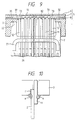
- Fig. 11 illustrates a third embodiment of the invention, which relates to the mutual positioning of the vibrators 11 and the cavity unit 5.
- the widths of the vibrator-positioning member 12 to be provided on the two outermost sides of the vibrators 11 are widened and slits 13 are formed at the accurate position with reference to the vibrators in the leading end faces thereof, so that the positioning pins provided on the lower surface of the elastic plate 8 can be fitted into the slits 13, respectively.
- the vibrators 11 and the cavity unit 5 are directly connected to each other to thereby be able to enhance their mutual positioning accuracy in the surface direction.
- Fig. 12 illustrates a fourth embodiment, which relates to the positioning of the vibrators 11 and cavity unit 5.
- the front edge of a plate-shaped piezoelectric element 1 is arranged so as to project a distance which corresponds to the leading ends of two positioning portions 22 provided on the two sides of a fixing plate 2, and then the piezoelectric element 1 and the fixing plate 2 are bonded to each other. Subsequently, the piezoelectric element 1 is cut and divided into a large number of vibrators 11, so that the leading ends of the respective vibrators 11 can be matched to the positioning portions 22 with accuracy.
- the vibrators 11 are positioned in surface direction using slit 21 and pin 51, and positioned in displace direction when placing ends of the positioning portions 22 with the elastic place 8.
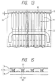
- Fig. 13 illustrates a fifth embodiment of the invention in which the front edge of a piezoelectric element 1 is projected out a slight length g beyond the leading ends of two positioning portions 22 respectively provided on the two side portions of a fixing plate 2 and then the piezoelectric element 1 and fixing plate 2 are bonded to each other. Subsequently, the piezoelectric element 1 is cut and divided into a large number of vibrators 11.
- the fifth embodiment when a cavity unit 5 is mounted to the leading ends of the two positioning portions 22, which function as a reference for positioning, on the two side portions of the fixing plate 2, then the leading ends of the vibrators 11 are strongly abutted against an elastic plate 8 in such a manner that the elastic plate 8 is slightly flexed toward a pressure chamber 72. Accordingly, the thickness of an adhesive to be applied to the leading ends of the vibrators 11 can be reduced. Alternatively, this may be omitted.
- Figs. 14(a) and 14(b) illustrate a sixth embodiment of a cavity unit 5 according to the invention.
- the chamber partation wall 77 of the flow passage plate 7, which defines an ink flow passage is composed of a thick layer 74 and a thin layer 75, and the thick layer 74 is arranged to have a wide width W1 and the thin layer 75 is arranged to have a narrow width W2.
- the area of the connecting surface thereof remains unchanged so that the rigidity of the wall 77 can be maintained. Also, by uniformly setting a ration T/W of the thicknesses T1, T2 and widths W1, W2 of the two layers 74, 75, the rigidity is enhanced to thereby ensure stable ink jetting.
- Fig. 15 illustrates a seventh embodiment in which a flow passage plate 7 is composed of three layers 74, 75, 76, and the width W2 of the middle layer 75 is set narrower than those of the remaining layers. Accordingly, even if the three layers are shifted in the surface direction thereof when they are corrected together, the strength and rididity of the wall can be maintained constant.
- an ink jet recording head wherein the movement of a piezoelectric element moves part of an ink flow passage substrate so as to jet out ink stored therein in the form of ink droplets, said ink jet recording head comprising:
- the piezoelectric vibrators are formed by dividing the piezoelectric element into the vibrators while a front edge thereof is positioned and fixed relative to two positioning projections respectively disposed on the two sides of the fixing plate.
- Two positioning projections are engaged with portions of the ink flow passage substrate so as to position the ink flow passage substrate relative to the piezoelectric vibrators in directions along a plane defined by the ink flow passage substrate.
- Selected ones of the piezoelectric vibrators that are respectively situated on both outermost sides of the plurality of piezoelectric vibrators are used as vibrator positioning member which are coupled to portions of the ink flow passage substrate which do not have an ink flow passage associated therewith.
- Leading ends of said vibrator-positioning member are engaged with said ink flow passage substrate so as to define a relative position between the ink flow passage substrate and the piezoelectric vibrators.
- a signal electrode is formed on each of the piezoelectric vibrators.
- Positioning portions are formed on a top surface of the holding means, said positioning portions being engaged with the piezoelectric vibrators so as to define a relative position between the holding means and the piezoelectric vibrators.
- An epoxy adhesive (b) combined with an adhesive (a) of an ultraviolet-curable type is inserted in a connecting portion gap defined between the holding means and the fixing plate.
- Both sides of a pressure chamber defined in the flow passage forming plate are wall elements and the wall elements are coupled to the vibrator-positioning member so as to position said vibrator-positioning member in the displacement direction of the piezoelectric vibrators.
- a flow passage forming plate is composed of at least two layers and the widths of the partition walls which define ink flow passages respectively formed in said respective layers are different from one another.
- a flat layer is formed on the surface of said elastic plate, said flat layer being in contact with the piezoelectric vibrators and the ink flow passage substrate, said piezoelectric vibrators being connected with each other by virtue of said flat layer.
- the plurality of piezoelectric vibrators constitutes a vibrator set, said holding means positioning and holding a plurality of vibrator sets.
- the ink jet recording head further comprises an electrode film formed on the fixing plate, said electrode film being divided together with the piezoelectric film to provide a plurality of signal electrodes corresponding to the piezoelectric vibrating elements, respectively.
- the holding means and the positioning member position the piezoelectric vibrators in a width direction thereof, and the holding means and said fixing plate position the piezoelectric vibrators in a thick direction thereof.
- an ink jet recording head wherein the movement of a piezoelectric element moves part of an ink flow passage substrate so as to jet out ink stored therein in the form of ink droplets, said ink jet recording head comprising:
- a process for forming an ink jet recording head wherein the movement of a piezoelectric element moves part of an ink flow passage substrate so as to jet out ink stored therein, comprises the steps of:
- a process for forming an ink jet recording head wherein the movement of a piezoelectric element moves part of an ink flow passage substrate so as to jet out ink stored therein, said process comprises the steps of:
- a process for forming an ink jet recording head wherein the movement of a piezoelectric element moves part of an ink flow passage substrate so as to jet out ink stored therein, said process comprises the steps of:
- a process for forming an ink jet recording head wherein the movement of a piezoelectric element moves part of an ink flow passage substrate so as to jet out ink stored therein, said process comprises the steps of:
Landscapes
- Engineering & Computer Science (AREA)
- Manufacturing & Machinery (AREA)
- Particle Formation And Scattering Control In Inkjet Printers (AREA)
Abstract
- a fixing plate (2),
- a plurality of piezoelectric vibrators (11) obtainable by cutting and dividing said plage-shaped piezoelectric element (1) while said piezoelectric element is fixed on said fixing plate (2),
- holding means (3) for positioning and holding at least one of said piezoelectric vibrators (11) and said fixing plate (2) in a direction perpendicular to the displacement direction of said piezoelectric vibrators (11), and
- an ink flow passage substrate (5) mounted on said holding means (3) and including a nozzle plate (6), an ink flow passage forming plate (7) and an elastic plate (8).
Description
- The present invention relates to an ink jet recording head wherein the movement of a piezoelectric element moves part of an ink flow passage substrate so as to jet out ink stored therein in the form of ink droplets.
- There has been known, from Japanese Patent Unexamined Publication No. Sho 58-119870, etc., an ink jet recording head employing a piezoelectric vibrator which moves in the longitudinal direction to apply pressure to ink stored within a pressure chamber, and the pressurized ink is then jetted out from a nozzle as droplets of ink onto a recording medium.
- In the recording head of the above-mentioned type, a large number of piezoelectric vibrators are inserted into guide holes formed in the upper and lower portions of a support member to thereby position and support the respective base end portions and leading end portions thereof. However, in this structure, the piezoelectric vibrators cannot be disposed in a high density arrangement. Also, they may be unevenly in the longitudinal direction thereof, and may be inclined with respect to each other, which makes it impossible to provide a uniform ink jet characteristic.
- Document EP-A-0 126 649 discloses a fluid jet print head that includes a manifold which defines an elongated cavity, and an orifice plate defining a plurality of orifices. A piezoelectric means is mounted in the cavity and spaced from the orifice plate to define a fluid reservoir therebetween. The transducer arrangement also includes acoustic isolation material such that unwanted wave propagation along the transducer is prevented.
- Document JP-A-32 34 538 discloses a method for producing an ink jet recording head in which a plurality of ink chambers are formed by inserting a plurality of teeth of a piezoelectric actuator into a plurality of grooves that are etched into a substrate. The transducer thus produced is formed with a minimal number of assembly steps.
- It is an object of the invention to provide a new ink jet recording head which is capable of positioning and connecting a plurality of piezoelectric vibrators, as well as various components forming the recording head, with respect to one another with high accuracy.
- This object is solved by the ink jet recording head of
independent claim - Further advantageous features aspects and details of the invention are evident from the dependent claims, the description and the drawings.
- The invention provides an ink jet recording head for use in an ink jet recording device which ejects drops of ink to thereby form an image and, more particularly, an ink jet recording head having a mechanism for precisely positioning the respective components of the head.
- In attaining the above object, according to one aspect of the invention, after a plate-shaped piezoelectric element is previously positioned and fixed onto a fixing plate, the piezoelectric element is divided into a plurality of piezoelectric vibrators, and piezoelectric vibrators are held and positioned in the surface direction thereof by a holding device.
- According to another aspect of the invention, the outermost piezoelectric vibrators are used as vibrator-positioning members to thereby enhance the working accuracy of the remaining vibrators used for ink jetting. Also, the vibrator-positioning member vibrators are used for positioning the vibrators with respect to the holding device or an ink flow passage substrate.
- According to still another aspect of the invention, a pressure chamber in a flow passage substrate is formed in such a manner that both side portions thererof respectively have a plane, and the vibrator-positioning members are respectively opposite to these planar side portions of the ink flow passage substrate, thereby enhancing the positioning accuracy between the ink flow passage forming substrate and the piezoelectric vibrators in the displacement direction thereof.
- According to a further aspect of the invention, positioning projections respectively provided on both sides of the fixing plate, which serve as a positioning reference for the piezoelectric vibrators, are used as the positioning portions that position the ink flow passage substrate in the surface direction thereof, so that the piezoelectric vibrators and the ink flow passage substrate can be positioned directly.
- Fig. 1 is a sectional side view of an ink jet recording head according to a first embodiment of the invention;
- Fig. 2 is a sectional side view of the ink jet recording head, taken from the position of a
pin 34; - Figs. 3 (a) to 3(d) are views of a piezoelectric element and a fixing plate, respectively showing steps of producing the piezoelectric vibrators;
- Fig. 4 is an explanatory view of a connection relationship between a piezoelectric vibrator and a fixing plate;
- Fig. 5 in a plan view of a positioning hole according to a first embodiment of the invention;
- Fig. 6 is a plan view of a cavity unit employed in the invention;
- Fig. 7 is a sectional view of main portions of the ink jet recording head;
- Fig. 8 is a view of a connecting portion between a piezoelectric vibrator and an elastic plate;
- Fig. 9 is a sectional view of the ink jet recording head according to another embodiment of the invention;
- Fig. 10 is a view of a connecting portion between a piezoelectric vibrator, a fixing plate and a holding frame;
- Fig. 11 is a plan view of a piezoelectric vibrator according to third embodiment;
- Fig. 12 is a section view of the ink jet recording head according to fourth embodiment;
- Fig. 13 is a sectional view of a fifth embodiment of an ink jet recording head according to the invention;
- Figs. 14(a) and 14(b) are sectional views of a sixth embodiment of a cavity unit according to another embodiment; and
- Fig. 15 is a sectional view of a seventh embodiment of a cavity unit according to still another embodiment.
- Figs. 1 and 2 illustrate an ink jet recording head according to a first embodiment of the invention. The ink jet recording head includes a plate-shaped lamination-type
piezoelectric element 1 which, as will be described later, is cut into rectangular pieces which are mounted on afixing plate 2 to provide a large number ofvibrators 11. Aholding frame 3 holds thevibrators 11 and positions them in the surface direction of acavity unit 5. Thecavity unit 5 is positioned and held onto theholding frame 3 by apositioning pin 34.Reference numeral 38 denotes a cover which supports the outer peripheral portion of thecavity unit 5.Reference numerals reference numeral 9 indicates a head circuit board. - Figs. 3(a) to 3(d) and 4 illustrate the
piezoelectric element 1 andfixing plate 2. Thefixing plate 2 is formed of free-cutting ceramics or the like, and includes anelectrode 24 on the top surface thereof. Thefixing plate 2 is substantially of a U-shape having positioningportions 22 protruded from both ends thereof. The plate-shapedpiezoelectric element 1 has anelectrode 14 on the lower surface and the rear end face thereof (see Fig. 4). Thepiezoelectric element 1 is firmly adhered to thefixing plate 2 in such a manner that the leading edge of thepiezoelectric element 1 is protruded from anedge 23 by a given length for keeping an active length L constant, and also theelectrode 14 on the lower surface of theelement 1 are in contact with theelectrode 24 of thefixing plate 2. - The
piezoelectric element 1 is formed to have a width which is greater than the length of a corresponding nozzle array. After it is fixed to thefixing plate 2, thepiezoelectric element 1 is sliced into a plurality ofvibrators 11, and two vibrator-positioning members 12 each pitch between vibrators having a width corresponding to the pitch of a nozzle 61 (see Fig. 6), by use of a slicing machine such as a wire saw or the like (see Fig. 3(c)). In this case, two rectangular parts respectively formed on the two outermost sides of thesevibrators 11 are used as vibrator-positioning members 12. Thevibrator positioning members 12 serve to absorb any deformation of the two side ends of the vibrators which occurs during the slicing operation, and to protect thethin vibrators 11. - Also, the
electrode 24, disposed on the surface of thefixing plate 2 whosepositioning member 22 serves to supplement the vibrator-positioning member, is cut into a large number ofsignal electrodes 25, which respectively correspond to thevibrators 11, during the slicing operation. Thesignal electrodes 25 are connected torespective lead wires 29, and thelead wires 29 are connected to the head circuit board 9 (see Fig. 1). On the other hand, twocommon electrodes 26 are respectively connected to thelead frames 28 which extend to thehead circuit board 9. A thin conductive film such as flexible cable or metal plate is electrically attachedelectrode 15 of eachvibrators 11 and both ends offilm 27 is connected to thecommon electrodes 26. - Referring again to Figs. 1 and 2, the
holding frame 3, which positions and holds thevibrators 11 and thefixing plate 2, is formed of an epoxy resin or other material in a cylindrical shape having a skirt likeportion 31 which fans out at the bottom. The skirt likeportion 31, more particularly, the interior of theskirt portion 31, receives therespective lead wires head circuit board 9 is mounted onto the bottom of the skirt likeportion 31 in a stable manner. - In the drawings,
reference numeral 36 designates an inclined guide surface which is formed so as to taper toward thepositioning hole 33 so as to facilitate the insertion of thepiezoelectric element 1. - The
holding frame 3, which holds thepiezoelectric element 1 and thefixing plate 2, has apositioning hole 33 on the top surface 32 (see Figs. 1 and 5). Thepositioning hole 33 includes awide portion 33a into which thefixing plate 2 can be fitted with a slight clearance δ1 in the thickness direction thereof, and a narrow portion 33b into which thevibrators 11 can be fitted with a slight clearance δ2 in the width direction thereof. Thewide portion 33a is used to position thefixing plate 2 in the thickness direction, and also the narrow portion 33b is used to position thepiezoelectric vibrators 11 in the width direction thereof, whereby thepiezoelectric vibrators 11 can be accurately positioned in the surface direction of thecavity unit 5. - As illustrated in Fig. 7, the
cavity unit 5 to be positioned and held on thetop surface 32 of aholding frame 3 with apositioning pin 34 includes anozzle plate 6 having anozzle 61 formed therein, aflow passage plate 7 defining an ink flow passage, and anelastic plate 8. - As shown in Fig. 6, the
nozzle plate 6 employed in the present embodiment includes two sets of nozzles, each set consisting of two arrays of nozzles, each array consisting of 12 nozzles 61 (only some of which are indicated). It should be noted that the vibrator-positioning member 12 do not have a nozzle associated therewith. Also, theflow passage plate 7 which is formed of a photo-curable resin is placed on thenozzle plate 6. Theflow passage plate 7 includes 4 arrays of pressure chambers, each array consisting of 12pressure chambers 72. Each of thepressure chambers 72, which are formed in a rectangular shape, are in communication with acommon ink chamber 71. Specifically, thenozzles 61 are respectively in communication with the ends of thepressure chambers 72 which are disposed so as to correspond thereto. - Also, the
elastic plate 8, which is placed on the surface of theflow passage plate 7, is formed of a thin plate such as an electroforming nickel product or the like. Theelastic plate 8 includes a plurality of ring-shapedthin portions 81 which extend along the inner edges of therespective pressure chambers 72. Further, as shown in Fig. 8, in the portions of theelastic plate 8 surrounded by thethin portions 81, there are formed high rididthick portions 82 which abut against the leading ends of thevibrators 11. Each of thethick portions 82 is arranged such that it has a width smaller than the thickness of thevibrator 11. - The
thin portions 81 and thethick portions 82 can be formed separately from each other. Alternatively, thethick portions 82 may be formed by forming a plating or a resin layer on athin film 81. - As shown in Figs. 2 and 6, if recessed or holed
portions 51 respectively formed in thecavity unit 5 are fitted with two positioningpins 34 respectively projecting from the top surface of the holdingframe 3 to thereby position thecavity unit 5 relative to the holdingframe 3 accurately. Also, as shown in Fig. 1, the respective leading ends of the vibrator-positioningmember 12 provided on both outermost portions or thevibrators 11 are abutted againstflat surfaces 73 of theelastic plate 8 disposed on both sides of thepressure chamber 72 so that thecavity unit 5 and thevibrators 11 are positioned accurately in a direction along which thevibrators 11 are displaced. - In the ink jet recording head constructed in the above-mentioned manner, the
piezoelectric element 1 is bounded to the fixingplate 2 such that the front edge of theelement 1 is projected out to a given length from anedge 23 of the fixing plate 2 (see Figs. 3(a) and 3(b)). Subsequently, thepiezoelectric element 1 is cut and divided into a large number of portions to thereby provide 12vibrators 11 and two vibrator-positioningmembers 12. - Next, the
piezoelectric element 1 or fixingplate 2 must be strongly fixed to holdingframe 3 by interposing an adhesive in the clearance of the holdingframe 3 in order to control the vibratory movements of the fixingplate 2. An epoxy adhesive having an excellent fusing property is desirable when the holding frame is formed of an epoxy resin and the fixingplate 2 is formed of a ceramics. - When such an adhesive is heated so that it can be quickly hardened, the leading ends of the
vibrators 11 draw back or draw out with reference to the top surface of the holdingframe 3 due to the different materials and shapes betweenvibrators 11 and the fixingplate 2, the holdingframe 3. For this reason, in the present embodiment, as shown in Fig. 10, a UV-curing adhesive a is at first coated on the connecting portion as a provisional adhesive. That is, the UV adhesive a is applied to the connecting portion and then is irradiated with ultraviolet rays to be hardened. Subsequently, an epoxy adhesive b is injected between the holdingframe 3 and the fixingplate 2 to thereby firmly bond the fixingplate 2 to the holdingframe 3 under lower temperature or room temperature. Thecavity unit 5 is then mounted in such a manner that the recessedportions 51 thereof are engaged with the respective positioning pins 34 projecting from the holdingframe 3. Next, outside of two vibrator-positioningmember 12 are fitted into thepositioning hole 33 formed in thetop surface 32 of the holdingframe 3 to thereby position thevibrators 11 in the widthwise direction thereof. At the same time, thevibrators 11 are positioned in the thickness direction thereof by means of the fixingplate 2. Further, the respective leading end portions of the vibrator-positioningmember 12 are abutted against theflat surface 73 provided on both sides of each pressure chambers array through theelastic plate 8, thereby positioning thevibrators 11 and thecavity unit 5 in the displacement direction thereof. - Fig. 9 illustrates another embodiment of the invention, which relates to the positioning of the
vibrators 11 and thecavity unit 5 in the displacement direction. In this embodiment, intead of the vibrator-positioningmember 12 used in the above-mentioned embodiment, the positioningmember 22 on the leading end of the fixingplate 2 is abutted against apositioning step 35 of the holdingframe 3 so that thevibrators 11 is positioned in the displacement direction with accuracy. - Fig. 11 illustrates a third embodiment of the invention, which relates to the mutual positioning of the
vibrators 11 and thecavity unit 5. In this embodiment, the widths of the vibrator-positioningmember 12 to be provided on the two outermost sides of thevibrators 11 are widened and slits 13 are formed at the accurate position with reference to the vibrators in the leading end faces thereof, so that the positioning pins provided on the lower surface of theelastic plate 8 can be fitted into theslits 13, respectively. - According to the third embodiment, the
vibrators 11 and thecavity unit 5 are directly connected to each other to thereby be able to enhance their mutual positioning accuracy in the surface direction. - Fig. 12 illustrates a fourth embodiment, which relates to the positioning of the
vibrators 11 andcavity unit 5. In the fourth embodiment, the front edge of a plate-shapedpiezoelectric element 1 is arranged so as to project a distance which corresponds to the leading ends of twopositioning portions 22 provided on the two sides of a fixingplate 2, and then thepiezoelectric element 1 and the fixingplate 2 are bonded to each other. Subsequently, thepiezoelectric element 1 is cut and divided into a large number ofvibrators 11, so that the leading ends of therespective vibrators 11 can be matched to thepositioning portions 22 with accuracy. - According to this embodiment, the
vibrators 11 are positioned in surfacedirection using slit 21 andpin 51, and positioned in displace direction when placing ends of thepositioning portions 22 with theelastic place 8. - Fig. 13 illustrates a fifth embodiment of the invention in which the front edge of a
piezoelectric element 1 is projected out a slight length g beyond the leading ends of twopositioning portions 22 respectively provided on the two side portions of a fixingplate 2 and then thepiezoelectric element 1 and fixingplate 2 are bonded to each other. Subsequently, thepiezoelectric element 1 is cut and divided into a large number ofvibrators 11. According to the fifth embodiment, when acavity unit 5 is mounted to the leading ends of the twopositioning portions 22, which function as a reference for positioning, on the two side portions of the fixingplate 2, then the leading ends of thevibrators 11 are strongly abutted against anelastic plate 8 in such a manner that theelastic plate 8 is slightly flexed toward apressure chamber 72. Accordingly, the thickness of an adhesive to be applied to the leading ends of thevibrators 11 can be reduced. Alternatively, this may be omitted. - Figs. 14(a) and 14(b) illustrate a sixth embodiment of a
cavity unit 5 according to the invention. In the sixth embodiment, thechamber partation wall 77 of theflow passage plate 7, which defines an ink flow passage, is composed of athick layer 74 and athin layer 75, and thethick layer 74 is arranged to have a wide width W1 and thethin layer 75 is arranged to have a narrow width W2. - According to the sixth embodiment, even if the two
layers wall 77 can be maintained. Also, by uniformly setting a ration T/W of the thicknesses T1, T2 and widths W1, W2 of the twolayers - According to this embodiment, there is a still more advantage that one can keep a wide span W3 of the pressure chamber without decreasing a ridigity of wall, then one can get a large volume of ink droplet even if in the case of high density pressure chamber.
- Fig. 15 illustrates a seventh embodiment in which a
flow passage plate 7 is composed of threelayers middle layer 75 is set narrower than those of the remaining layers. Accordingly, even if the three layers are shifted in the surface direction thereof when they are corrected together, the strength and rididity of the wall can be maintained constant. - According to another aspect of the invention, there is provided an ink jet recording head wherein the movement of a piezoelectric element moves part of an ink flow passage substrate so as to jet out ink stored therein in the form of ink droplets, said ink jet recording head comprising:
- a fixing plate, a plurality of piezoelectric vibrators obtainable by cutting and dividing the plage-shaped piezoelectric element while the piezoelectric element is fixed on said fixing plate, holding means for positioning and holding at least one of the piezoelectric vibrators and the fixing plate in a direction perpendicular to the displacement direction of the piezoelectric vibrators, an ink flow passage substrate mounted on the holding means and including a nozzle plate, an ink flow passage forming plate and an elastic plate, and a positioning member engaged with the ink flow passage substrate and the holding means so as to regulate the relative position thereof.
- The piezoelectric vibrators are formed by dividing the piezoelectric element into the vibrators while a front edge thereof is positioned and fixed relative to two positioning projections respectively disposed on the two sides of the fixing plate. Two positioning projections are engaged with portions of the ink flow passage substrate so as to position the ink flow passage substrate relative to the piezoelectric vibrators in directions along a plane defined by the ink flow passage substrate. Selected ones of the piezoelectric vibrators that are respectively situated on both outermost sides of the plurality of piezoelectric vibrators are used as vibrator positioning member which are coupled to portions of the ink flow passage substrate which do not have an ink flow passage associated therewith. Leading ends of said vibrator-positioning member are engaged with said ink flow passage substrate so as to define a relative position between the ink flow passage substrate and the piezoelectric vibrators.
- Further a signal electrode is formed on each of the piezoelectric vibrators.
- Positioning portions are formed on a top surface of the holding means, said positioning portions being engaged with the piezoelectric vibrators so as to define a relative position between the holding means and the piezoelectric vibrators. An epoxy adhesive (b) combined with an adhesive (a) of an ultraviolet-curable type is inserted in a connecting portion gap defined between the holding means and the fixing plate. Both sides of a pressure chamber defined in the flow passage forming plate are wall elements and the wall elements are coupled to the vibrator-positioning member so as to position said vibrator-positioning member in the displacement direction of the piezoelectric vibrators. A flow passage forming plate is composed of at least two layers and the widths of the partition walls which define ink flow passages respectively formed in said respective layers are different from one another. A flat layer is formed on the surface of said elastic plate, said flat layer being in contact with the piezoelectric vibrators and the ink flow passage substrate, said piezoelectric vibrators being connected with each other by virtue of said flat layer.
- The plurality of piezoelectric vibrators constitutes a vibrator set, said holding means positioning and holding a plurality of vibrator sets.
- The ink jet recording head further comprises an electrode film formed on the fixing plate, said electrode film being divided together with the piezoelectric film to provide a plurality of signal electrodes corresponding to the piezoelectric vibrating elements, respectively. The holding means and the positioning member position the piezoelectric vibrators in a width direction thereof, and the holding means and said fixing plate position the piezoelectric vibrators in a thick direction thereof.
- According to a further aspect of the invention, there is provided an ink jet recording head wherein the movement of a piezoelectric element moves part of an ink flow passage substrate so as to jet out ink stored therein in the form of ink droplets, said ink jet recording head comprising:
- a fixing plate, a plurality of piezoelectric vibrators obtainable by cutting and dividing said plate-shaped piezoelectric element while said piezoelectric element is fixed on said fixing plate, holding means for positioning and holding at least one of said piezoelectric vibrators and said fixing plate in a direction perpendicular to the displacement direction of said piezoelectric vibrators, an ink flow passage substrate mounted on said holding means and including a nozzle plate, an ink flow passage forming plate and an elastic plate, and a vibrator-positioning member coupled with said ink flow passage substrate to position said piezoelectric vibrators in a displacement direction thereof. The piezoelectric elements comprise multi-layer piezoelectric elements, and the fixing plate reinforces said vibrator-positioning member.
- According to a further aspect of the invention, a process for forming an ink jet recording head wherein the movement of a piezoelectric element moves part of an ink flow passage substrate so as to jet out ink stored therein, comprises the steps of:
- attaching a plate shaped piezoelectric element to a fixing plate, cutting said piezoelectric element into a plurality of piezoelectric vibrators, Inserting said piezoelectric vibrators, mounted on said fixing plate, into a holding device, mounting an ink flow passage substrate on said holding device so as to be in contact with said piezoelectric vibrators, engaging a positioning member with said ink flow passage substrate and said holding device so as to regulate the relative position thereof.
- According to a further aspect of the invention, a process for forming an ink jet recording head wherein the movement of a piezoelectric element moves part of an ink flow passage substrate so as to jet out ink stored therein, said process comprises the steps of:
- attaching a plate shaped piezoelectric element to a fixing plate, cutting said piezoelectric element into a plurality of piezoelectric vibrators, mounting an ink flow passage substrate on said holding device so as to be in contact with said piezoelectric vibrators, inserting said piezoelectric vibrators, mounted on said fixing plate, into a holding device, engaging a positioning member with said ink flow passage substrate and said holding device so as to regulate the relative position thereof.
- According to a further aspect of the invention, a process for forming an ink jet recording head wherein the movement of a piezoelectric element moves part of an ink flow passage substrate so as to jet out ink stored therein, said process comprises the steps of:
- widening widths of a vibrator-positioning member to be provided on the two outermost sides of vibrators, forming slits in leading end faces of said vibrators, and fitting positioning pins provided on a surface of an elastic plate into said slits, respectively.
- According to a further aspect of the invention, a process for forming an ink jet recording head wherein the movement of a piezoelectric element moves part of an ink flow passage substrate so as to jet out ink stored therein, said process comprises the steps of:
- arranging a front edge of a plate-shaped piezoelectric element so as to project a distance which corresponds to leading ends of two positioning portions provided on the two sides of a fixing plate, bonding said piezoelectric element and said fixing plate to each other, and cutting and dividing said piezoelectric element into a large number of vibrators so that leading ends of said respective vibrators are matched to said positioning portions with accuracy.
Claims (12)
- An ink jet recording head wherein the movement of a piezoelectric element (1) moves part of an ink flow passage substrate (5) so as to jet out ink stored therein in the form of ink droplets, said ink jet recording head comprising:a fixing plate (2),a plurality of piezoelectric vibrators (11) obtainable by cutting and dividing said plage-shaped piezoelectric element (1) while said piezoelectric element is fixed on said fixing plate (2),holding means (3) for positioning and holding at least one of said piezoelectric vibrators (11) and said fixing plate (2) in a direction perpendicular to the displacement direction of said piezoelectric vibrators (11), andan ink flow passage substrate (5) mounted on said holding means (3) and including a nozzle plate (6), an ink flow passage forming plate (7) and an elastic plate (8).
- An ink jet recording head as claimed in claim 1, further comprising a positioning member engaged with said ink flow passage substrate (5) and said holding means (3) so as to regulate the relative position thereof.
- An ink jet recording head as claimed in any one of the preceding claims, wherein said holding means (3) and a vibrator-positioning member (12) position said piezoelectric vibrators (11) in a widthwise direction thereof.
- An ink jet recording head as claimed in any one of the preceding claims, wherein said holding means (3) and said fixing plate (2) position said piezoelectric vibrators (11) in a thickness direction thereof reinforces said vibrator-positioning member (12).
- An ink jet recording head as claimed in any one of claims 2 to 4, wherein selected ones of said piezoelectric vibrators that are respectively situated on both outermost sides of said plurality of piezoelectric vibrators (11) are used as vibrator-positioning member (12) which are coupled to portions of said ink flow passage substrate (5) which do not have an ink flow passage associated therewith.
- An ink jet recording head as claimed in Claim 5, wherein leading ends of said vibrator-positioning member (12) are engaged with said ink flow passage substrate (5) so as to define a relative position between said ink flow passage substrate and said piezoelectric vibrators (11).
- An ink jet recording head as claimed in any one of the preceding claims, wherein positioning portions are formed on a top surface (32) of said holding means (3), said positioning portions being engaged with said piezoelectric vibrators (11) so as to define a relative position between said holding means (3) and said piezoelectric vibrators (11).
- An ink jet recording head as claimed in claim 5 or 6, wherein both sides of a pressure chamber defined in said flow passage forming plate (7) are wall elements and said wall elements are coupled to said vibrator-positioning member so as to position said vibrator-positioning member in the displacement direction of said piezoelectric vibrators (11).
- An ink jet recording head as claimed in claim 1, wherein a flat layer is formed on the surface of said elastic plate (8), said flat layer being in contact with said piezoelectric vibrators (11) and said ink flow passage substrate (5), said piezoelectric vibrators being connected with each other by virtue of said flat layer.
- An ink jet recording head as claimed in any one of the preceding claims, wherein said plurality of piezoelectric vibrators (11) constitutes a vibrator set, said holding means (3) positioning and holding a plurality of vibrator sets.
- An ink jet recording head as claimed in any one of the preceding claims, wherein said piezoelectric elements (11) comprise multi-layer piezoelectric elements.
- An ink jet recording head wherein the movement of a piezoelectric element moves part of an ink flow passage substrate so as to jet out ink stored therein in the form of ink droplets, said ink jet recording head comprising:a fixing plate (2);a plurality of piezoelectric vibrators (11) fixed to said fixing plate (2) and obtainable by cutting and dividing a plate-shaped piezoelectric element (1) while said plate-shaped piezoelectric element (1) is fixed on said fixing plate (2);holding means (3) which holds and positions said fixing plate (2) and at least one of said piezoelectric vibrators (11) in the directions perpendicular to the displacement direction of said piezoelectric vibrators (11); andan ink flow passage substrate (5) mounted on said holding means (3) so as to regulate the relative position thereof and including a nozzle plate (6), an ink flow passage forming plate (7) and an elastic plate (8) connected with one or more of said piezoelectric vibrators (11).
Applications Claiming Priority (22)
| Application Number | Priority Date | Filing Date | Title |
|---|---|---|---|
| JP34534391 | 1991-12-26 | ||
| JP345343/91 | 1991-12-26 | ||
| JP34534391A JP3199076B2 (en) | 1991-12-26 | 1991-12-26 | Ink jet recording head and piezoelectric unit for ink jet recording head |
| JP2283392A JP3173520B2 (en) | 1992-02-07 | 1992-02-07 | Ink jet head and method of manufacturing the same |
| JP22833/92 | 1992-02-07 | ||
| JP2283392 | 1992-02-07 | ||
| JP2512692A JP3262134B2 (en) | 1992-02-12 | 1992-02-12 | Ink jet recording head and method of manufacturing the same |
| JP25126/92 | 1992-02-12 | ||
| JP2512692 | 1992-02-12 | ||
| JP4519592A JP3246517B2 (en) | 1992-03-03 | 1992-03-03 | Inkjet head |
| JP4519592 | 1992-03-03 | ||
| JP45195/92 | 1992-03-03 | ||
| JP8400392 | 1992-04-06 | ||
| JP84003/92 | 1992-04-06 | ||
| JP8400392A JP3149890B2 (en) | 1992-04-06 | 1992-04-06 | Inkjet head |
| JP10305992A JP3185812B2 (en) | 1992-04-22 | 1992-04-22 | Inkjet head |
| JP103060/92 | 1992-04-22 | ||
| JP10306092 | 1992-04-22 | ||
| JP103059/92 | 1992-04-22 | ||
| JP10306092 | 1992-04-22 | ||
| JP10305992 | 1992-04-22 | ||
| EP92121977A EP0550030B1 (en) | 1991-12-26 | 1992-12-24 | Ink jet recording head and process for forming same |
Related Parent Applications (2)
| Application Number | Title | Priority Date | Filing Date |
|---|---|---|---|
| EP92121977.0 Division | 1992-12-24 | ||
| EP92121977A Division EP0550030B1 (en) | 1991-12-26 | 1992-12-24 | Ink jet recording head and process for forming same |
Publications (3)
| Publication Number | Publication Date |
|---|---|
| EP0795404A2 true EP0795404A2 (en) | 1997-09-17 |
| EP0795404A3 EP0795404A3 (en) | 2000-11-02 |
| EP0795404B1 EP0795404B1 (en) | 2005-06-08 |
Family
ID=27563981
Family Applications (2)
| Application Number | Title | Priority Date | Filing Date |
|---|---|---|---|
| EP97108517A Expired - Lifetime EP0795404B1 (en) | 1991-12-26 | 1992-12-24 | Ink jet recording head |
| EP92121977A Expired - Lifetime EP0550030B1 (en) | 1991-12-26 | 1992-12-24 | Ink jet recording head and process for forming same |
Family Applications After (1)
| Application Number | Title | Priority Date | Filing Date |
|---|---|---|---|
| EP92121977A Expired - Lifetime EP0550030B1 (en) | 1991-12-26 | 1992-12-24 | Ink jet recording head and process for forming same |
Country Status (4)
| Country | Link |
|---|---|
| US (2) | US5517225A (en) |
| EP (2) | EP0795404B1 (en) |
| DE (2) | DE69224975T2 (en) |
| HK (1) | HK1010045A1 (en) |
Cited By (1)
| Publication number | Priority date | Publication date | Assignee | Title |
|---|---|---|---|---|
| WO2007137950A1 (en) * | 2006-05-31 | 2007-12-06 | Siemens Aktiengesellschaft | Fully active piezo actuator, and method for the production thereof |
Families Citing this family (16)
| Publication number | Priority date | Publication date | Assignee | Title |
|---|---|---|---|---|
| US5764257A (en) | 1991-12-26 | 1998-06-09 | Seiko Epson Corporation | Ink jet recording head |
| US5786833A (en) * | 1993-10-07 | 1998-07-28 | Seiko Epson Corporation | Piezoelectric driver for an ink jet recording head, including front end plate having front end face aligned with front end face of inactive region of driver |
| JP3235635B2 (en) * | 1993-11-29 | 2001-12-04 | セイコーエプソン株式会社 | Inkjet recording head |
| JP3422342B2 (en) * | 1994-03-28 | 2003-06-30 | セイコーエプソン株式会社 | Inkjet recording head |
| JP3235638B2 (en) * | 1994-07-25 | 2001-12-04 | セイコーエプソン株式会社 | Ink jet recording head and method of manufacturing the same |
| US5757400A (en) * | 1996-02-01 | 1998-05-26 | Spectra, Inc. | High resolution matrix ink jet arrangement |
| JP3589277B2 (en) * | 1997-01-27 | 2004-11-17 | セイコーエプソン株式会社 | Ink jet recording head |
| EP0860279B1 (en) | 1997-02-21 | 2002-05-22 | Seiko Epson Corporation | Ink jet recording head |
| DE60006878T2 (en) * | 1999-03-29 | 2004-10-14 | Seiko Epson Corp. | Ink jet recording head, piezoelectric vibrator element unit and method of manufacturing the piezoelectric vibrator element unit |
| US6578953B2 (en) | 1999-03-29 | 2003-06-17 | Seiko Epson Corporation | Inkjet recording head, piezoelectric vibration element unit used for the recording head, and method of manufacturing the piezoelectric vibration element unit |
| DE60232955D1 (en) | 2001-03-01 | 2009-08-27 | Ngk Insulators Ltd | COMPROMISE, PIEZOELECTRIC ADJUSTABLE MEMBER AND METHOD OF MANUFACTURING THEREOF |
| EP1707363B1 (en) * | 2002-03-18 | 2012-07-25 | Seiko Epson Corporation | Liquid jet head and liquid jet apparatus |
| JP5188158B2 (en) * | 2006-12-15 | 2013-04-24 | キヤノン株式会社 | Method for manufacturing ink jet recording head |
| US8029110B2 (en) * | 2007-11-05 | 2011-10-04 | Seiko Epson Corporation | Droplet ejection head and droplet ejection apparatus |
| US8029111B2 (en) | 2007-11-05 | 2011-10-04 | Seiko Epson Corporation | Droplet ejection head and droplet ejection apparatus |
| JP4865688B2 (en) * | 2007-12-11 | 2012-02-01 | セイコーエプソン株式会社 | Droplet discharge head and droplet discharge apparatus |
Citations (9)
| Publication number | Priority date | Publication date | Assignee | Title |
|---|---|---|---|---|
| JPS59162061A (en) * | 1983-03-07 | 1984-09-12 | Hitachi Koki Co Ltd | On-demand type printing-head |
| EP0126649A2 (en) * | 1983-05-19 | 1984-11-28 | The Mead Corporation | Fluid jet print head |
| JPS61283553A (en) * | 1985-06-10 | 1986-12-13 | Ricoh Co Ltd | Vibration unit of ink jet head and its manufacturing |
| JPS63265646A (en) * | 1987-11-20 | 1988-11-02 | Nec Corp | Manufacture of jet head |
| US4937589A (en) * | 1989-08-23 | 1990-06-26 | Eastman Kodak Company | Continuous ink jet print heads |
| JPH02220848A (en) * | 1989-02-23 | 1990-09-04 | Seiko Epson Corp | Plastic ink jet head |
| JPH0373347A (en) * | 1989-08-14 | 1991-03-28 | Ricoh Co Ltd | Ink-jet recording device |
| JPH03234538A (en) * | 1990-02-09 | 1991-10-18 | Sharp Corp | Production of ink jet recording head |
| JPH03272857A (en) * | 1990-03-23 | 1991-12-04 | Sharp Corp | Ink jet record head |
Family Cites Families (13)
| Publication number | Priority date | Publication date | Assignee | Title |
|---|---|---|---|---|
| US3900162A (en) * | 1974-01-10 | 1975-08-19 | Ibm | Method and apparatus for generation of multiple uniform fluid filaments |
| US4095232A (en) * | 1977-07-18 | 1978-06-13 | The Mead Corporation | Apparatus for producing multiple uniform fluid filaments and drops |
| US4250510A (en) * | 1979-09-04 | 1981-02-10 | The Mead Corporation | Fluid jet device |
| JPS58119871A (en) * | 1982-01-04 | 1983-07-16 | データプロダクツ コーポレイション | Ink jet device |
| US4439780A (en) * | 1982-01-04 | 1984-03-27 | Exxon Research And Engineering Co. | Ink jet apparatus with improved transducer support |
| JPS608953A (en) * | 1983-06-29 | 1985-01-17 | Omron Tateisi Electronics Co | Program analyzer |
| DE3342844A1 (en) * | 1983-11-26 | 1985-06-05 | Philips Patentverwaltung Gmbh, 2000 Hamburg | MICROPLANAR INK JET PRINT HEAD |
| US4768266A (en) * | 1986-08-29 | 1988-09-06 | Dataproducts Corporation | Method of making an ink jet printer transducer array |
| JPH0245985A (en) * | 1988-08-08 | 1990-02-15 | Nippon Telegr & Teleph Corp <Ntt> | Heat sinking mounting substrate of photocircuit element and packaging |
| JP2841397B2 (en) * | 1988-12-01 | 1998-12-24 | セイコーエプソン株式会社 | Inkjet recording head |
| DE68906001T2 (en) * | 1988-12-07 | 1993-09-09 | Seiko Epson Corp | On-demand inkjet print head. |
| JPH02277640A (en) * | 1989-04-19 | 1990-11-14 | Seiko Epson Corp | Ink jet head |
| JP2802138B2 (en) * | 1990-03-15 | 1998-09-24 | シャープ株式会社 | Inkjet recording head |
-
1992
- 1992-12-24 DE DE69224975T patent/DE69224975T2/en not_active Expired - Lifetime
- 1992-12-24 DE DE69233523T patent/DE69233523T2/en not_active Expired - Lifetime
- 1992-12-24 EP EP97108517A patent/EP0795404B1/en not_active Expired - Lifetime
- 1992-12-24 EP EP92121977A patent/EP0550030B1/en not_active Expired - Lifetime
- 1992-12-28 US US07/997,571 patent/US5517225A/en not_active Expired - Lifetime
-
1995
- 1995-06-06 US US08/471,230 patent/US5630274A/en not_active Expired - Lifetime
-
1998
- 1998-09-22 HK HK98110817A patent/HK1010045A1/en not_active IP Right Cessation
Patent Citations (9)
| Publication number | Priority date | Publication date | Assignee | Title |
|---|---|---|---|---|
| JPS59162061A (en) * | 1983-03-07 | 1984-09-12 | Hitachi Koki Co Ltd | On-demand type printing-head |
| EP0126649A2 (en) * | 1983-05-19 | 1984-11-28 | The Mead Corporation | Fluid jet print head |
| JPS61283553A (en) * | 1985-06-10 | 1986-12-13 | Ricoh Co Ltd | Vibration unit of ink jet head and its manufacturing |
| JPS63265646A (en) * | 1987-11-20 | 1988-11-02 | Nec Corp | Manufacture of jet head |
| JPH02220848A (en) * | 1989-02-23 | 1990-09-04 | Seiko Epson Corp | Plastic ink jet head |
| JPH0373347A (en) * | 1989-08-14 | 1991-03-28 | Ricoh Co Ltd | Ink-jet recording device |
| US4937589A (en) * | 1989-08-23 | 1990-06-26 | Eastman Kodak Company | Continuous ink jet print heads |
| JPH03234538A (en) * | 1990-02-09 | 1991-10-18 | Sharp Corp | Production of ink jet recording head |
| JPH03272857A (en) * | 1990-03-23 | 1991-12-04 | Sharp Corp | Ink jet record head |
Non-Patent Citations (7)
| Title |
|---|
| PATENT ABSTRACTS OF JAPAN vol. 009, no. 014 (M-352), 22 January 1985 (1985-01-22) & JP 59 162061 A (HITACHI KOKI KK;OTHERS: 01), 12 September 1984 (1984-09-12) * |
| PATENT ABSTRACTS OF JAPAN vol. 011, no. 149 (M-588), 15 May 1987 (1987-05-15) & JP 61 283553 A (RICOH CO LTD), 13 December 1986 (1986-12-13) * |
| PATENT ABSTRACTS OF JAPAN vol. 013, no. 060 (M-796), 10 February 1989 (1989-02-10) & JP 63 265646 A (NEC CORP), 2 November 1988 (1988-11-02) * |
| PATENT ABSTRACTS OF JAPAN vol. 014, no. 523 (M-1049), 16 November 1990 (1990-11-16) & JP 02 220848 A (SEIKO EPSON CORP), 4 September 1990 (1990-09-04) * |
| PATENT ABSTRACTS OF JAPAN vol. 015, no. 235 (M-1125), 17 June 1991 (1991-06-17) & JP 03 073347 A (RICOH CO LTD), 28 March 1991 (1991-03-28) * |
| PATENT ABSTRACTS OF JAPAN vol. 016, no. 016 (M-1200), 16 January 1992 (1992-01-16) & JP 03 234538 A (SHARP CORP), 18 October 1991 (1991-10-18) * |
| PATENT ABSTRACTS OF JAPAN vol. 016, no. 090 (M-1218), 5 March 1992 (1992-03-05) & JP 03 272857 A (SHARP CORP), 4 December 1991 (1991-12-04) * |
Cited By (1)
| Publication number | Priority date | Publication date | Assignee | Title |
|---|---|---|---|---|
| WO2007137950A1 (en) * | 2006-05-31 | 2007-12-06 | Siemens Aktiengesellschaft | Fully active piezo actuator, and method for the production thereof |
Also Published As
| Publication number | Publication date |
|---|---|
| EP0795404B1 (en) | 2005-06-08 |
| US5517225A (en) | 1996-05-14 |
| US5630274A (en) | 1997-05-20 |
| DE69233523D1 (en) | 2005-07-14 |
| EP0550030A3 (en) | 1993-08-25 |
| HK1010045A1 (en) | 1999-06-11 |
| DE69224975T2 (en) | 1998-07-30 |
| DE69233523T2 (en) | 2006-03-16 |
| DE69224975D1 (en) | 1998-05-07 |
| EP0795404A3 (en) | 2000-11-02 |
| EP0550030B1 (en) | 1998-04-01 |
| EP0550030A2 (en) | 1993-07-07 |
Similar Documents
| Publication | Publication Date | Title |
|---|---|---|
| EP0550030B1 (en) | Ink jet recording head and process for forming same | |
| US5471232A (en) | Ink jet recording head | |
| JPH041052A (en) | On-demand type ink-jet printing head | |
| JP3452129B2 (en) | Ink jet recording head and ink jet recording apparatus | |
| US6286942B1 (en) | Ink jet recording head with mechanism for positioning head components | |
| US7156504B2 (en) | Liquid ejection head | |
| US20060187274A1 (en) | Housing used in inkjet head | |
| JP3114771B2 (en) | Ink jet head and method of manufacturing the same | |
| EP0867287B1 (en) | Ink jet recording head | |
| JPH068423A (en) | Ink jet recording head | |
| JPH05220956A (en) | Ink jet reocrding head | |
| JP3185372B2 (en) | Inkjet head | |
| US7163279B2 (en) | Inkjet head having relay member interposed between piezoelectric element and diaphragm | |
| JP3185812B2 (en) | Inkjet head | |
| JP3114766B2 (en) | Ink jet head and method of manufacturing the same | |
| KR100252697B1 (en) | Recording liquid ejection apparatus of printer head and manufacturing method thereof | |
| JP3491193B2 (en) | Ink jet recording head and ink jet recording apparatus | |
| JP3362787B2 (en) | Piezoelectric unit for inkjet recording head | |
| JP3473034B2 (en) | Inkjet recording head | |
| JP3591571B2 (en) | Ink jet recording head and method of manufacturing the same | |
| JP3152262B2 (en) | Ink jet recording head and method of manufacturing the same | |
| JP3427894B2 (en) | Piezoelectric unit for inkjet recording head and method of manufacturing the same | |
| JP2659819B2 (en) | Droplet ejector | |
| JP3109013B2 (en) | Ink jet recording head and method of manufacturing the same | |
| JP3149902B2 (en) | Piezoelectric driver for inkjet recording head and method of manufacturing the same |
Legal Events
| Date | Code | Title | Description |
|---|---|---|---|
| PUAI | Public reference made under article 153(3) epc to a published international application that has entered the european phase |
Free format text: ORIGINAL CODE: 0009012 |
|
| 17P | Request for examination filed |
Effective date: 19970527 |
|
| AC | Divisional application: reference to earlier application |
Ref document number: 550030 Country of ref document: EP |
|
| AK | Designated contracting states |
Kind code of ref document: A2 Designated state(s): CH DE FR GB IT LI NL SE |
|
| PUAL | Search report despatched |
Free format text: ORIGINAL CODE: 0009013 |
|
| AK | Designated contracting states |
Kind code of ref document: A3 Designated state(s): CH DE FR GB IT LI NL SE |
|
| RIC1 | Information provided on ipc code assigned before grant |
Free format text: 7B 41J 2/025 A, 7B 41J 2/16 B, 7B 41J 2/14 B |
|
| 17Q | First examination report despatched |
Effective date: 20020522 |
|
| GRAP | Despatch of communication of intention to grant a patent |
Free format text: ORIGINAL CODE: EPIDOSNIGR1 |
|
| GRAS | Grant fee paid |
Free format text: ORIGINAL CODE: EPIDOSNIGR3 |
|
| GRAA | (expected) grant |
Free format text: ORIGINAL CODE: 0009210 |
|
| AC | Divisional application: reference to earlier application |
Ref document number: 0550030 Country of ref document: EP Kind code of ref document: P |
|
| AK | Designated contracting states |
Kind code of ref document: B1 Designated state(s): CH DE FR GB IT LI NL SE |
|
| REG | Reference to a national code |
Ref country code: GB Ref legal event code: FG4D |
|
| REG | Reference to a national code |
Ref country code: CH Ref legal event code: EP |
|
| REF | Corresponds to: |
Ref document number: 69233523 Country of ref document: DE Date of ref document: 20050714 Kind code of ref document: P |
|
| REG | Reference to a national code |
Ref country code: SE Ref legal event code: TRGR |
|
| REG | Reference to a national code |
Ref country code: CH Ref legal event code: NV Representative=s name: BOVARD AG PATENTANWAELTE |
|
| ET | Fr: translation filed | ||
| PLBE | No opposition filed within time limit |
Free format text: ORIGINAL CODE: 0009261 |
|
| STAA | Information on the status of an ep patent application or granted ep patent |
Free format text: STATUS: NO OPPOSITION FILED WITHIN TIME LIMIT |
|
| 26N | No opposition filed |
Effective date: 20060309 |
|
| REG | Reference to a national code |
Ref country code: HK Ref legal event code: WD Ref document number: 1002953 Country of ref document: HK |
|
| PGFP | Annual fee paid to national office [announced via postgrant information from national office to epo] |
Ref country code: SE Payment date: 20091207 Year of fee payment: 18 Ref country code: CH Payment date: 20091215 Year of fee payment: 18 |
|
| PGFP | Annual fee paid to national office [announced via postgrant information from national office to epo] |
Ref country code: NL Payment date: 20091216 Year of fee payment: 18 |
|
| PGFP | Annual fee paid to national office [announced via postgrant information from national office to epo] |
Ref country code: IT Payment date: 20091219 Year of fee payment: 18 |
|
| REG | Reference to a national code |
Ref country code: CH Ref legal event code: PFA Owner name: SEIKO EPSON CORPORATION Free format text: SEIKO EPSON CORPORATION#4-1, NISHISHINJUKU 2-CHOME#SHINJUKU-KU TOKYO (JP) -TRANSFER TO- SEIKO EPSON CORPORATION#4-1, NISHISHINJUKU 2-CHOME#SHINJUKU-KU TOKYO (JP) |
|
| PGFP | Annual fee paid to national office [announced via postgrant information from national office to epo] |
Ref country code: GB Payment date: 20101222 Year of fee payment: 19 |
|
| REG | Reference to a national code |
Ref country code: NL Ref legal event code: V1 Effective date: 20110701 |
|
| REG | Reference to a national code |
Ref country code: CH Ref legal event code: PL |
|
| REG | Reference to a national code |
Ref country code: SE Ref legal event code: EUG |
|
| PG25 | Lapsed in a contracting state [announced via postgrant information from national office to epo] |
Ref country code: SE Free format text: LAPSE BECAUSE OF NON-PAYMENT OF DUE FEES Effective date: 20101225 |
|
| PG25 | Lapsed in a contracting state [announced via postgrant information from national office to epo] |
Ref country code: CH Free format text: LAPSE BECAUSE OF NON-PAYMENT OF DUE FEES Effective date: 20101231 Ref country code: LI Free format text: LAPSE BECAUSE OF NON-PAYMENT OF DUE FEES Effective date: 20101231 |
|
| PG25 | Lapsed in a contracting state [announced via postgrant information from national office to epo] |
Ref country code: IT Free format text: LAPSE BECAUSE OF NON-PAYMENT OF DUE FEES Effective date: 20101224 Ref country code: NL Free format text: LAPSE BECAUSE OF NON-PAYMENT OF DUE FEES Effective date: 20110701 |
|
| PGFP | Annual fee paid to national office [announced via postgrant information from national office to epo] |
Ref country code: FR Payment date: 20111219 Year of fee payment: 20 |
|
| PGFP | Annual fee paid to national office [announced via postgrant information from national office to epo] |
Ref country code: DE Payment date: 20111221 Year of fee payment: 20 |
|
| REG | Reference to a national code |
Ref country code: DE Ref legal event code: R071 Ref document number: 69233523 Country of ref document: DE |
|
| REG | Reference to a national code |
Ref country code: GB Ref legal event code: PE20 Expiry date: 20121223 |
|
| PG25 | Lapsed in a contracting state [announced via postgrant information from national office to epo] |
Ref country code: GB Free format text: LAPSE BECAUSE OF EXPIRATION OF PROTECTION Effective date: 20121223 |