EP0787505A1 - Active fixation medical electrical lead having improved turning tool - Google Patents
Active fixation medical electrical lead having improved turning tool Download PDFInfo
- Publication number
- EP0787505A1 EP0787505A1 EP97300155A EP97300155A EP0787505A1 EP 0787505 A1 EP0787505 A1 EP 0787505A1 EP 97300155 A EP97300155 A EP 97300155A EP 97300155 A EP97300155 A EP 97300155A EP 0787505 A1 EP0787505 A1 EP 0787505A1
- Authority
- EP
- European Patent Office
- Prior art keywords
- housing
- electrical lead
- roller assembly
- medical electrical
- turning tool
- Prior art date
- Legal status (The legal status is an assumption and is not a legal conclusion. Google has not performed a legal analysis and makes no representation as to the accuracy of the status listed.)
- Granted
Links
Images


Classifications
-
- A—HUMAN NECESSITIES
- A61—MEDICAL OR VETERINARY SCIENCE; HYGIENE
- A61N—ELECTROTHERAPY; MAGNETOTHERAPY; RADIATION THERAPY; ULTRASOUND THERAPY
- A61N1/00—Electrotherapy; Circuits therefor
- A61N1/02—Details
- A61N1/04—Electrodes
- A61N1/05—Electrodes for implantation or insertion into the body, e.g. heart electrode
- A61N1/056—Transvascular endocardial electrode systems
- A61N1/057—Anchoring means; Means for fixing the head inside the heart
- A61N1/0573—Anchoring means; Means for fixing the head inside the heart chacterised by means penetrating the heart tissue, e.g. helix needle or hook
-
- A—HUMAN NECESSITIES
- A61—MEDICAL OR VETERINARY SCIENCE; HYGIENE
- A61N—ELECTROTHERAPY; MAGNETOTHERAPY; RADIATION THERAPY; ULTRASOUND THERAPY
- A61N1/00—Electrotherapy; Circuits therefor
- A61N1/02—Details
- A61N1/04—Electrodes
- A61N1/05—Electrodes for implantation or insertion into the body, e.g. heart electrode
- A61N1/056—Transvascular endocardial electrode systems
- A61N1/057—Anchoring means; Means for fixing the head inside the heart
- A61N2001/0578—Anchoring means; Means for fixing the head inside the heart having means for removal or extraction
Landscapes
- Health & Medical Sciences (AREA)
- Cardiology (AREA)
- Heart & Thoracic Surgery (AREA)
- Vascular Medicine (AREA)
- Engineering & Computer Science (AREA)
- Biomedical Technology (AREA)
- Nuclear Medicine, Radiotherapy & Molecular Imaging (AREA)
- Radiology & Medical Imaging (AREA)
- Life Sciences & Earth Sciences (AREA)
- Animal Behavior & Ethology (AREA)
- General Health & Medical Sciences (AREA)
- Public Health (AREA)
- Veterinary Medicine (AREA)
- Electrotherapy Devices (AREA)
Abstract
Description
- This invention relates to the field of body-implantable medical device systems, and in particular to a body-implantable medical device system which includes an active fixation medical electrical lead having an improved turning tool.
- In the medical field, various types of body-implantable leads are known and used. Cardiac pulse generators, in particular, use implanted leads to both sense cardiac function and deliver stimulation pulses. One type of commonly used implantable lead is an endocardial lead.
- Endocardial leads are attached at their proximal end to an implantable pulse generator and at their distal end to the endocardium of a cardiac chamber. Often the lead assembly is inserted into the heart through a vein. The lead generally has an inner conductor covered by an insulative sheath.
- The distal end of an endocardial lead may engage the endocardium by either an active fixation mechanism or a passive fixation mechanism. Passive fixation mechanisms, such as a tine assembly, lodge or passively fix the lead to the heart. Active fixation mechanisms use a structure, such as a helix or hook, to engage into or actively fix themselves to the heart.
- A sharpened helix has been found to provide a reasonably secure means for fixing a lead to the heart. An exposed sharpened helix may damage a vein, however, during introduction. Thus many active fixation leads have helixes which either retract into the lead body or are shielded during introduction. See for example, U.S. Patent No. 4,972,848 of Di Domenico (helix shielded within lead body which may be extended to engage cardiac tissue); U.S. Patent No. 5,003,992 of Holleman et al. (plunger through helix guards against damage to tissue by the helix and may be retracted to engage cardiac tissue) and U.S. Patent No. 4,827,940 of Mayer et al. (soluble cover shields helix until positioned proximate fixation site.) Among the most preferred methods of shielding a helix is where the helix may be retracted within or extended from the lead body.
- An example of the more common means for extending or retracting a helix may be seen in the U.S. Patent No. 4,106,512 of Bisping. As seen, such a lead design features a fixation helix to be retracted within or extended from the lead body which is actuated by rotation of the conductor. In particular, rotation of the connector pin rotates the conductor coil, which in turn rotates the fixation helix, thereby causing it to extend or retract.
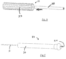
- Presently, so-called "Bisping" leads require a connector pin wrench to rotate the connector pin to thus extend or retract the fixation helix, as depicted in FIG. 1. As seen, a connector pin wrench is attached to the connector pin and is rotated by holding the connector assembly in one hand and rotating the wrench with the other hand.
- Thus it is an object of the present invention to provide an active fixation lead having an improved turning tool which will permit a fixation helix to be retracted within or extended from the lead body with only one hand.
- The above and other objects are met by the present invention which is directed to an active-fixation medical electrical lead having an improved turning tool. In particular, the lead has a fixation helix attached to a coiled conductor, the coiled conductor is attached at the opposite end to a connector pin of a connector assembly. The coiled conductor is covered by an insulative sheath between the fixation helix and the connector assembly. Mating with the connector assembly is the improved turning tool. The turning tool includes a housing, a roller assembly, and in the preferred embodiment a header. The housing is shaped so as to frictionally couple with a sealing ring of the connector assembly while permitting a connector pin of the connector assembly to extend therethrough and into the roller assembly. Through such a combination the roller assembly may be rotated relative to the housing thereby causing the connector pin to rotate relative to the sealing ring and thus extend or retract the fixation helix. The header further permits a stylet to be guided through the turning tool and remain within the lead while in use. Ultimately such a device permits a physician to extend as well as retract a helix with only one hand.
- The above-described and other aspects of the present invention may be better understood and appreciated with reference to the following detailed description of a specific embodiment of the invention, given by way of example only, when read in conjunction with the accompanying drawings, wherein:
- FIG. 1 is a perspective view of a prior art connector pin wrench attached to a connector pin.
- FIG. 2 is a perspective view of an improved turning tool according to the present invention.
- FIG. 3 is a view of the distal end of the turning tool shown in FIG. 2.
- FIG. 4 is an exploded view of the roller assembly used in the improved turning tool.
- FIG. 5 is a perspective view of the header used in the improved turning tool.
- FIG. 6 is a cross sectional view of the improved turning tool shown in FIG.1.
- FIG. 7 is a greatly enlarged side cross-sectional view of a medical electrical lead having active fixation which may be extended or retracted with the improved turning tool shown in FIGS 2-6.
- The Figures are not necessarily to scale.
- For the purposes of this specification and claims, the term "lead" is used herein in its broadest sense and includes a stimulation lead, a sensing lead, a combination thereof or any other elongated member, such as a catheter, which may usefully be introduced into a body.
- As previously discussed, FIG.1 depicts the operation of the connector pin wrench of the prior art. As seen, the
connector pin wrench 1 was connected to the connector pin 2 of alead 3.Lead 3 was held with onehand 4 whileconnector pin wrench 1 was rotated indirection 5 with theopposing hand 6. As such, the prior artconnector pin wrench 1 required two hands to manipulate. As seen,stylet 10 was permitted to be in place within the lead. This is important as lead maneuverability is greatly enhanced by a stylet. - FIG.2 is a perspective view of an improved
turning tool 20 for use in the present invention. As seen, the turning tool has essentially three components:housing 21,roller assembly 22 andheader 23. The proximal end ofheader 23 features a funnelshaped opening 24 designed to guide a stylet into a guide tube (discussed below).Housing 21 featuresconnector bars distal end 19 which define openings between the ends of the housing giving access to the roller assembly.Connector bars roller assembly 22 to avoid pinching a rubber glove during manipulation. - FIG.3 shows the
distal end 19 ofhousing 21. As seen, the distal end ofhousing 21 features a funnel-shapedconnector pin hole 29 which is sized to have a connector pin inserted therethrough. The connector pin when inserted through the connector pin hole meets withroller assembly 22, depicted in detail in FIG.4. - As seen in FIG. 4,
roller assembly 22 has two parts, aroller 27 and anelastomeric friction tube 28.
Friction tube 28 is sized to be inserted through and fit within the lumen throughroller 27. The diameter of the lumen withinfriction tube 28 is sized, in turn, to form a friction fit over a connector pin. In the preferred embodiment, the diameter of the lumen withinfriction tube 28 is approximately .056 inches (1.4mm) in diameter which corresponds to a standard size connector pin, such as the industry standard IS1 or IS2.Roller assembly 22 has a knurled surface and is sized to mate withplastic header 23, as depicted in FIG. 6. - FIG.5 depicts
header 23. As seen,header 23 has two parts,header body 30 andguide tube 31 therethrough.Header body 30 features at its proximal end a funnel shapedopening 24 to guide a stylet (not shown) into theguide tube 31.Guide tube 31 is mounted withinheader body 30. - FIG. 6 is a cross sectional view of the
turning tool 20. As seen, the proximal end ofheader 23 has the funnel shapedopening 24 designed to guide a stylet into the guide tube. As further seen,header body 30 is designed so as to have aspacing 41 between itself andhousing 21, as well as to have afurther spacing 42 between itself and guidetube 31. This provides for spacings suitable for aeration during the sterilization process, preferably using ethylene oxide as is well known in the art. As seen, guidetube 31 extends into the lumen ofroller 27, and in particular withinfriction tube 28. As also seen, connector bars 25, 26 are separated from the surface of theroller assembly 22 byspacings - The turning tool is constructed of the following materials:
header body 30,housing 21 androller 27 are made from polysulfone, although any other resterilizable polymer or material may also be used.Guide tube 31 is made of stainless steel whilefriction tube 28 is made from silicone, although other elastomeric materials may also be used. - The
roller 27 is axially supported on the guide tube and may be rotated by a physician's fingers acting on the knurled surface between thebars - Turning now to FIG. 7 which depicts a medical electrical lead having an active fixation which may be activated using the improved turning tool, lead 50 has essentially three sections: electrode assembly 51, lead body 52 and
connector assembly 53. Electrode assembly 51 features ahelix 54 fitted aboutinner conductor 55 usingcrimp 56 andcore pin 57.Helix 54 is disposed through acap seal assembly 58 andindicator ring 59. At the distal end is MCRD cap 60 around which is fitted an MCRD (monolithic controlled release device) 61.MCRD 61 is provided to elute a steroid or any other anti-inflammatory drug in the area abouthelix 54. Proximal to MCRD cap 60 issleeve head 62.Sleeve head 62 meets into TR (tip-ring) spacer 63 which in turns leads toelectrode ring 64.Electrode ring 64 meets with outer coiledconductor 65. Covering outer coiledconductor 65 is outerinsulated sleeve 71 whileinner coil conductor 55 is covered by innerinsulated sleeve 72. - In the preferred embodiment, inner and outer
insulative sleeves -
Conductors -
Helix 54 andelectrode ring 64 are preferably a polished platinum alloy although other biocompatible conductors may be used. - Lead body 52 thus is essentially inner coiled
conductor 55 covered byinner insulative sheath 72 which in turn is covered by outer coiledconductor 65 and finally covered byouter insulative sheath 71. - At the proximal end of lead body 52 is
connector assembly 53. As seen,connector assembly 53 essentially has sealingrings 80 disposed on either side ofconnector ring 81. At the most proximal end ofconnector assembly 53 isconnector pin 82.Connector ring 81 is electrically coupled toouter conductor 65 whileconnector pin 82 is electrically coupled toinner conductor 55. Through such a construction,connector ring 81 is thus electrically coupled toring electrode 64 whileconnector pin 82 is electrically coupled tohelix 54.Connector pin 82, moreover, is mechanically coupled as seen toinner conductor 55 such that rotation ofconnector pin 82 in a first direction causeshelix 54 to rotate in the first direction. - The improved turning tool is used to implant the lead and manipulate the helix. In particular the tool is mated with the connector pin during the lead implantation process in order to provide a means for extending or retracting the fixation helix. Once the helix is properly positioned the tool is removed from the connector pin and the lead is electrically coupled to a pulse generator. The turning tool is not implanted with the lead.
- Although a specific embodiment of the invention has been disclosed, this is done for the purposes of illustration and is not intended to be limiting with regard to the scope of the invention. It is contemplated that various substitutions, alterations, and/or modifications, including but not limited to those specifically discussed herein, may be made to the disclosed embodiment of the invention without departing from the scope of the invention, which is defined in the appended claims, which follow.
Claims (9)
- A medical electrical lead system comprising:a medical electrical lead (50), the lead having a fixation helix (54) coupled to a first end of a coiled conductor (55), a second end of the coiled conductor being coupled to a connector pin (82), the coiled conductor being covered between the first end and the second end by an insulative sheath (71), a sealing ring (80) mounted to a proximal end of the insulative sheath; anda turning tool (20) coupled to the connector pin (82), the turning tool having a housing (21), the housing having a proximal end and a distal end, the distal end having a distal lumen (29), the distal lumen being sized to frictionally engage the sealing ring, a roller assembly (22) mounted within the housing and rotatable relative to the housing, the roller assembly having an inner lumen having an inner lumen diameter, the inner lumen diameter being sized to frictionally engage the connector pin (82) whereby rotation of the roller assembly relative to the housing causes the connector pin to rotate relative to the sealing ring.
- A medical electrical lead system according to claim 1, wherein the roller assembly has a roller assembly lumen, and a friction tube (28) mounted within the roller assembly lumen.
- A medical electrical lead system according to claim 1 or 2 wherein the distal lumen (29) is funnel-shaped.
- A medical electrical lead system according to claim 1, 2 or 3 further comprising a header (23) fitted within the proximal end of the housing (21).
- A medical electrical lead system according to any preceding claim, wherein the header is fitted with a guide tube (31) which axially supports the roller assembly (22) and provides an axial passage whereby a stylet may pass through the turning tool.
- A medical electrical lead system according to claim 4 or 5 comprising a funnel-shaped opening (24) in the header (23).
- A medical electrical lead system as claimed in any preceding claim, further comprising a ring electrode (64), the ring electrode being coupled to a first end of a second coiled conductor (65), a second end of the second coiled conductor being coupled to a connector ring (81); the coiled second conductor being covered between its first end and its second end by said insulative sheath (71).
- A turning tool (20) for retracting and extending a helix of a medical electrical lead, comprisinga housing (21) having a first end and a second end, the housing having a lumen between the two ends, the housing having an opening positioned between the first end and the second end, the second end having a sealing ring lumen (29) therethrough for frictionally engaging a sealing ring of a medical electrical lead;a header (23) positioned in the first end, the header having a proximal opening and a guide tube (31) mounted thereto, the guide tube communicating with the proximal opening of the header;a roller assembly (22) mounted within the housing lumen adjacent the housing opening, the roller assembly having a connector pin lumen therein for frictionally engaging a connector pin of the medical electrical lead.
- A turning tool as claimed in claim 8 wherein the roller assembly (22) is rotatably mounted on the guide tube (31).
Applications Claiming Priority (2)
| Application Number | Priority Date | Filing Date | Title |
|---|---|---|---|
| US08/585,218 US5741321A (en) | 1996-01-11 | 1996-01-11 | Active fixation medical electrical lead having improved turning tool |
| US585218 | 1996-01-11 |
Publications (2)
| Publication Number | Publication Date |
|---|---|
| EP0787505A1 true EP0787505A1 (en) | 1997-08-06 |
| EP0787505B1 EP0787505B1 (en) | 2002-12-18 |
Family
ID=24340513
Family Applications (1)
| Application Number | Title | Priority Date | Filing Date |
|---|---|---|---|
| EP97300155A Expired - Lifetime EP0787505B1 (en) | 1996-01-11 | 1997-01-13 | Active fixation medical electrical lead having improved turning tool |
Country Status (5)
| Country | Link |
|---|---|
| US (1) | US5741321A (en) |
| EP (1) | EP0787505B1 (en) |
| AU (1) | AU1011997A (en) |
| CA (1) | CA2194744C (en) |
| DE (1) | DE69717873T2 (en) |
Cited By (1)
| Publication number | Priority date | Publication date | Assignee | Title |
|---|---|---|---|---|
| DE202008012425U1 (en) | 2008-09-18 | 2009-02-12 | Biotronik Crm Patent Ag | Mandrineinführhilfe |
Families Citing this family (76)
| Publication number | Priority date | Publication date | Assignee | Title |
|---|---|---|---|---|
| US9061139B2 (en) * | 1998-11-04 | 2015-06-23 | Greatbatch Ltd. | Implantable lead with a band stop filter having a capacitor in parallel with an inductor embedded in a dielectric body |
| US6701176B1 (en) | 1998-11-04 | 2004-03-02 | Johns Hopkins University School Of Medicine | Magnetic-resonance-guided imaging, electrophysiology, and ablation |
| US8244370B2 (en) * | 2001-04-13 | 2012-08-14 | Greatbatch Ltd. | Band stop filter employing a capacitor and an inductor tank circuit to enhance MRI compatibility of active medical devices |
| US8219208B2 (en) * | 2001-04-13 | 2012-07-10 | Greatbatch Ltd. | Frequency selective passive component networks for active implantable medical devices utilizing an energy dissipating surface |
| US8989870B2 (en) * | 2001-04-13 | 2015-03-24 | Greatbatch Ltd. | Tuned energy balanced system for minimizing heating and/or to provide EMI protection of implanted leads in a high power electromagnetic field environment |
| US8712544B2 (en) | 2001-04-13 | 2014-04-29 | Greatbatch Ltd. | Electromagnetic shield for a passive electronic component in an active medical device implantable lead |
| US8457760B2 (en) | 2001-04-13 | 2013-06-04 | Greatbatch Ltd. | Switched diverter circuits for minimizing heating of an implanted lead and/or providing EMI protection in a high power electromagnetic field environment |
| US8509913B2 (en) * | 2001-04-13 | 2013-08-13 | Greatbatch Ltd. | Switched diverter circuits for minimizing heating of an implanted lead and/or providing EMI protection in a high power electromagnetic field environment |
| US7853325B2 (en) * | 2001-04-13 | 2010-12-14 | Greatbatch Ltd. | Cylindrical bandstop filters for medical lead systems |
| US8977355B2 (en) | 2001-04-13 | 2015-03-10 | Greatbatch Ltd. | EMI filter employing a capacitor and an inductor tank circuit having optimum component values |
| US7787958B2 (en) * | 2001-04-13 | 2010-08-31 | Greatbatch Ltd. | RFID detection and identification system for implantable medical lead systems |
| US7899551B2 (en) * | 2001-04-13 | 2011-03-01 | Greatbatch Ltd. | Medical lead system utilizing electromagnetic bandstop filters |
| US9295828B2 (en) | 2001-04-13 | 2016-03-29 | Greatbatch Ltd. | Self-resonant inductor wound portion of an implantable lead for enhanced MRI compatibility of active implantable medical devices |
| WO2002083016A1 (en) | 2001-04-13 | 2002-10-24 | Surgi-Vision, Inc. | Systems and methods for magnetic-resonance-guided interventional procedures |
| US20070088416A1 (en) * | 2001-04-13 | 2007-04-19 | Surgi-Vision, Inc. | Mri compatible medical leads |
| CA2487140C (en) | 2002-05-29 | 2011-09-20 | Surgi-Vision, Inc. | Magnetic resonance probes |
| US20040088033A1 (en) * | 2002-10-31 | 2004-05-06 | Smits Karel F.A.A. | Implantable medical lead designs |
| US8010207B2 (en) | 2002-10-31 | 2011-08-30 | Medtronic, Inc. | Implantable medical lead designs |
| EP2392382A1 (en) | 2005-11-11 | 2011-12-07 | Greatbatch Ltd. | Tank filters placed in series with the lead wires or circuits of active medical devices to enhance MRI compatibility |
| US7853324B2 (en) * | 2005-11-11 | 2010-12-14 | Greatbatch Ltd. | Tank filters utilizing very low K materials, in series with lead wires or circuits of active medical devices to enhance MRI compatibility |
| WO2007102893A2 (en) * | 2005-11-11 | 2007-09-13 | Greatbatch Ltd. | Tank filters placed in series with the lead wires or circuits of active medical devices to enhance mri compatibility |
| US8224462B2 (en) | 2005-11-11 | 2012-07-17 | Greatbatch Ltd. | Medical lead system utilizing electromagnetic bandstop filters |
| US8903505B2 (en) | 2006-06-08 | 2014-12-02 | Greatbatch Ltd. | Implantable lead bandstop filter employing an inductive coil with parasitic capacitance to enhance MRI compatibility of active medical devices |
| US8116862B2 (en) | 2006-06-08 | 2012-02-14 | Greatbatch Ltd. | Tank filters placed in series with the lead wires or circuits of active medical devices to enhance MRI compatibility |
| US7702387B2 (en) * | 2006-06-08 | 2010-04-20 | Greatbatch Ltd. | Tank filters adaptable for placement with a guide wire, in series with the lead wires or circuits of active medical devices to enhance MRI compatibility |
| US9042999B2 (en) * | 2006-06-08 | 2015-05-26 | Greatbatch Ltd. | Low loss band pass filter for RF distance telemetry pin antennas of active implantable medical devices |
| US8170692B2 (en) * | 2006-08-29 | 2012-05-01 | Pacesetter, Inc. | Implant tool for active fixation lead |
| US9031670B2 (en) | 2006-11-09 | 2015-05-12 | Greatbatch Ltd. | Electromagnetic shield for a passive electronic component in an active medical device implantable lead |
| US9468750B2 (en) | 2006-11-09 | 2016-10-18 | Greatbatch Ltd. | Multilayer planar spiral inductor filter for medical therapeutic or diagnostic applications |
| US11331488B2 (en) | 2007-03-09 | 2022-05-17 | Mainstay Medical Limited | Systems and methods for enhancing function of spine stabilization muscles associated with a spine surgery intervention |
| US10925637B2 (en) * | 2010-03-11 | 2021-02-23 | Mainstay Medical Limited | Methods of implanting electrode leads for use with implantable neuromuscular electrical stimulator |
| US11679261B2 (en) | 2007-03-09 | 2023-06-20 | Mainstay Medical Limited | Systems and methods for enhancing function of spine stabilization muscles associated with a spine surgery intervention |
| US11679262B2 (en) | 2007-03-09 | 2023-06-20 | Mainstay Medical Limited | Systems and methods for restoring muscle function to the lumbar spine |
| ES2827186T3 (en) | 2007-03-09 | 2021-05-20 | Mainstay Medical Ltd | Neuromuscular electrical stimulation system |
| US9072897B2 (en) | 2007-03-09 | 2015-07-07 | Mainstay Medical Limited | Systems and methods for restoring muscle function to the lumbar spine |
| WO2009002239A1 (en) * | 2007-06-28 | 2008-12-31 | St. Jude Medical Ab | Medical implantable lead and method for manufacturing the same |
| WO2009078752A1 (en) | 2007-12-18 | 2009-06-25 | St. Jude Medical Ab | Medical implantable lead and method for manufacturing of such a lead |
| US10080889B2 (en) | 2009-03-19 | 2018-09-25 | Greatbatch Ltd. | Low inductance and low resistance hermetically sealed filtered feedthrough for an AIMD |
| US9108066B2 (en) | 2008-03-20 | 2015-08-18 | Greatbatch Ltd. | Low impedance oxide resistant grounded capacitor for an AIMD |
| US7953495B2 (en) * | 2008-04-30 | 2011-05-31 | Medtronic, Inc. | Lead-implant coupling device |
| WO2010051265A1 (en) * | 2008-10-30 | 2010-05-06 | Greatbatch Ltd. | Capacitor and inductor elements physically disposed in series whose lumped parameters are electrically connected in parallel to form a bandstop filter |
| US8447414B2 (en) * | 2008-12-17 | 2013-05-21 | Greatbatch Ltd. | Switched safety protection circuit for an AIMD system during exposure to high power electromagnetic fields |
| WO2010114429A1 (en) | 2009-03-31 | 2010-10-07 | St. Jude Medical Ab | A medical implantable lead and a method for manufacturing of such a lead |
| US9950159B2 (en) | 2013-10-23 | 2018-04-24 | Mainstay Medical Limited | Systems and methods for restoring muscle function to the lumbar spine and kits for implanting the same |
| US11684774B2 (en) | 2010-03-11 | 2023-06-27 | Mainstay Medical Limited | Electrical stimulator for treatment of back pain and methods of use |
| US11786725B2 (en) | 2012-06-13 | 2023-10-17 | Mainstay Medical Limited | Systems and methods for restoring muscle function to the lumbar spine and kits for implanting the same |
| US9999763B2 (en) * | 2012-06-13 | 2018-06-19 | Mainstay Medical Limited | Apparatus and methods for anchoring electrode leads adjacent to nervous tissue |
| CN103079633B (en) | 2010-03-11 | 2016-05-04 | 梅恩斯塔伊医疗公司 | Be used for the treatment of modular stimulator, implanted RF ablation system and the using method of backache |
| US10350421B2 (en) | 2013-06-30 | 2019-07-16 | Greatbatch Ltd. | Metallurgically bonded gold pocket pad for grounding an EMI filter to a hermetic terminal for an active implantable medical device |
| US9427596B2 (en) | 2013-01-16 | 2016-08-30 | Greatbatch Ltd. | Low impedance oxide resistant grounded capacitor for an AIMD |
| US9931514B2 (en) | 2013-06-30 | 2018-04-03 | Greatbatch Ltd. | Low impedance oxide resistant grounded capacitor for an AIMD |
| US10596369B2 (en) | 2011-03-01 | 2020-03-24 | Greatbatch Ltd. | Low equivalent series resistance RF filter for an active implantable medical device |
| US11198014B2 (en) | 2011-03-01 | 2021-12-14 | Greatbatch Ltd. | Hermetically sealed filtered feedthrough assembly having a capacitor with an oxide resistant electrical connection to an active implantable medical device housing |
| US10272252B2 (en) | 2016-11-08 | 2019-04-30 | Greatbatch Ltd. | Hermetic terminal for an AIMD having a composite brazed conductive lead |
| US9138343B2 (en) * | 2011-05-31 | 2015-09-22 | Bayer Healthcare Llc | Tip protector sleeve |
| WO2013019853A1 (en) | 2011-08-02 | 2013-02-07 | Mainstay Medical, Inc. | Apparatus for anchoring electrode leads for use with implantable neuromuscular electrical stimulator |
| EP2773418B1 (en) * | 2011-11-04 | 2017-05-10 | Shanghai MicroPort Medical (Group) Co., Ltd. | Implantable active medical lead |
| EP2773419B1 (en) | 2011-11-04 | 2019-02-27 | Shanghai MicroPort Medical (Group) Co., Ltd. | Implantable passive medical lead |
| EP2773417B1 (en) | 2011-11-04 | 2019-06-19 | Shanghai MicroPort Medical (Group) Co., Ltd. | Implantable medical lead |
| US10195419B2 (en) | 2012-06-13 | 2019-02-05 | Mainstay Medical Limited | Electrode leads for use with implantable neuromuscular electrical stimulator |
| US9186501B2 (en) | 2012-06-13 | 2015-11-17 | Mainstay Medical Limited | Systems and methods for implanting electrode leads for use with implantable neuromuscular electrical stimulator |
| WO2014000234A1 (en) | 2012-06-28 | 2014-01-03 | Shanghai Microport Medical (Group) Co., Ltd. | Assembly of passive cardiac electrical lead |
| WO2014000237A1 (en) | 2012-06-28 | 2014-01-03 | Shanghai Microport Medical (Group) Co., Ltd. | Assembly of active cardiac electrical lead |
| US9278210B2 (en) | 2012-06-28 | 2016-03-08 | Shanghai Microport Medical (Group) Co., Ltd. | Bipolar active cardiac electrical lead |
| USRE46699E1 (en) | 2013-01-16 | 2018-02-06 | Greatbatch Ltd. | Low impedance oxide resistant grounded capacitor for an AIMD |
| US10471268B2 (en) | 2014-10-16 | 2019-11-12 | Mainstay Medical Limited | Systems and methods for monitoring muscle rehabilitation |
| WO2016168382A1 (en) | 2015-04-14 | 2016-10-20 | Cardiac Pacemakers, Inc. | Torque tool for fixable stimulation-sensing leads |
| US10327810B2 (en) | 2016-07-05 | 2019-06-25 | Mainstay Medical Limited | Systems and methods for enhanced implantation of electrode leads between tissue layers |
| US10249415B2 (en) | 2017-01-06 | 2019-04-02 | Greatbatch Ltd. | Process for manufacturing a leadless feedthrough for an active implantable medical device |
| JP7036920B2 (en) | 2017-11-06 | 2022-03-15 | ペースセツター、インコーポレイテツド | Biostimulator with fixed elements |
| US10912945B2 (en) | 2018-03-22 | 2021-02-09 | Greatbatch Ltd. | Hermetic terminal for an active implantable medical device having a feedthrough capacitor partially overhanging a ferrule for high effective capacitance area |
| US10905888B2 (en) | 2018-03-22 | 2021-02-02 | Greatbatch Ltd. | Electrical connection for an AIMD EMI filter utilizing an anisotropic conductive layer |
| US11577086B2 (en) | 2018-08-20 | 2023-02-14 | Pacesetter, Inc. | Fixation mechanisms for a leadless cardiac biostimulator |
| USD894396S1 (en) | 2019-03-08 | 2020-08-25 | Pacesetter, Inc. | Leadless biostimulator attachment feature |
| US11541243B2 (en) | 2019-03-15 | 2023-01-03 | Pacesetter, Inc. | Biostimulator having coaxial fixation elements |
| WO2023211673A1 (en) * | 2022-04-27 | 2023-11-02 | Pacesetter, Inc. | Pacing lead conversion tool |
Citations (9)
| Publication number | Priority date | Publication date | Assignee | Title |
|---|---|---|---|---|
| US4106512A (en) | 1976-12-16 | 1978-08-15 | Medtronic, Inc. | Transvenously implantable lead |
| EP0013605A1 (en) * | 1979-01-05 | 1980-07-23 | Medtronic, Inc. | Stylet insertion assembly for body implantable lead |
| EP0149431A2 (en) * | 1983-10-25 | 1985-07-24 | C.B. BIOELETTRONICA S.r.l. | Active anchored intracavitary electrocatheter with retractible spring wire |
| FR2575925A1 (en) * | 1985-01-16 | 1986-07-18 | Roudy Gil | Electrode for stimulation and detection cardiac lead |
| US4827940A (en) | 1987-04-13 | 1989-05-09 | Cardiac Pacemakers, Inc. | Soluble covering for cardiac pacing electrode |
| US4972848A (en) | 1989-08-23 | 1990-11-27 | Medtronic, Inc. | Medical electrical lead with polymeric monolithic controlled release device and method of manufacture |
| US5003992A (en) | 1989-08-23 | 1991-04-02 | Holleman Timothy W | Atraumatic screw-in lead |
| FR2677547A1 (en) * | 1991-06-12 | 1992-12-18 | Bens Jean Luc | Improvements to endocardiac probes, the distal end of which is equipped with an active grip system |
| FR2724566A1 (en) * | 1994-09-16 | 1996-03-22 | Dev Sed Soc Et | Motorised cardiac probe with electrode and retractable helix |
Family Cites Families (5)
| Publication number | Priority date | Publication date | Assignee | Title |
|---|---|---|---|---|
| US4624266A (en) * | 1983-12-19 | 1986-11-25 | Daig Corporation | Introducer tool for screw-in lead |
| US4967766A (en) * | 1989-05-16 | 1990-11-06 | Intermedics, Inc. | Implantable endocardial lead with fixation apparatus retractable by a lanyard |
| US5056516A (en) * | 1989-11-02 | 1991-10-15 | Intermedics, Inc. | Implantable endocordial lead with torque-transmitting lanyard |
| US5020545A (en) * | 1990-01-23 | 1991-06-04 | Siemens-Pacesetter, Inc. | Cardiac lead assembly and method of attaching a cardiac lead assembly |
| US5228455A (en) * | 1991-05-20 | 1993-07-20 | Siemens Pacesetter, Inc. | Implant tool for extendable/retractable positive fixation lead |
-
1996
- 1996-01-11 US US08/585,218 patent/US5741321A/en not_active Expired - Lifetime
-
1997
- 1997-01-09 CA CA002194744A patent/CA2194744C/en not_active Expired - Fee Related
- 1997-01-10 AU AU10119/97A patent/AU1011997A/en not_active Abandoned
- 1997-01-13 DE DE69717873T patent/DE69717873T2/en not_active Expired - Lifetime
- 1997-01-13 EP EP97300155A patent/EP0787505B1/en not_active Expired - Lifetime
Patent Citations (9)
| Publication number | Priority date | Publication date | Assignee | Title |
|---|---|---|---|---|
| US4106512A (en) | 1976-12-16 | 1978-08-15 | Medtronic, Inc. | Transvenously implantable lead |
| EP0013605A1 (en) * | 1979-01-05 | 1980-07-23 | Medtronic, Inc. | Stylet insertion assembly for body implantable lead |
| EP0149431A2 (en) * | 1983-10-25 | 1985-07-24 | C.B. BIOELETTRONICA S.r.l. | Active anchored intracavitary electrocatheter with retractible spring wire |
| FR2575925A1 (en) * | 1985-01-16 | 1986-07-18 | Roudy Gil | Electrode for stimulation and detection cardiac lead |
| US4827940A (en) | 1987-04-13 | 1989-05-09 | Cardiac Pacemakers, Inc. | Soluble covering for cardiac pacing electrode |
| US4972848A (en) | 1989-08-23 | 1990-11-27 | Medtronic, Inc. | Medical electrical lead with polymeric monolithic controlled release device and method of manufacture |
| US5003992A (en) | 1989-08-23 | 1991-04-02 | Holleman Timothy W | Atraumatic screw-in lead |
| FR2677547A1 (en) * | 1991-06-12 | 1992-12-18 | Bens Jean Luc | Improvements to endocardiac probes, the distal end of which is equipped with an active grip system |
| FR2724566A1 (en) * | 1994-09-16 | 1996-03-22 | Dev Sed Soc Et | Motorised cardiac probe with electrode and retractable helix |
Cited By (1)
| Publication number | Priority date | Publication date | Assignee | Title |
|---|---|---|---|---|
| DE202008012425U1 (en) | 2008-09-18 | 2009-02-12 | Biotronik Crm Patent Ag | Mandrineinführhilfe |
Also Published As
| Publication number | Publication date |
|---|---|
| DE69717873D1 (en) | 2003-01-30 |
| CA2194744A1 (en) | 1997-07-12 |
| CA2194744C (en) | 2004-10-05 |
| US5741321A (en) | 1998-04-21 |
| EP0787505B1 (en) | 2002-12-18 |
| DE69717873T2 (en) | 2003-11-20 |
| AU1011997A (en) | 1997-07-24 |
Similar Documents
| Publication | Publication Date | Title |
|---|---|---|
| EP0787505B1 (en) | Active fixation medical electrical lead having improved turning tool | |
| EP0709111B1 (en) | Medical electrical lead system having a torque transfer stylet | |
| US5522874A (en) | Medical lead having segmented electrode | |
| JP2520373B2 (en) | Subcutaneous implantable lead system | |
| US5575814A (en) | Active fixation medical electrical lead having mapping capability | |
| EP1284783B1 (en) | Introducer system for medical electrical lead | |
| US5342414A (en) | Transvenous defibrillation lead | |
| US5800496A (en) | Medical electrical lead having a crush resistant lead body | |
| CA2159948C (en) | Medical electrical lead having a reinforced tine assembly | |
| US4146036A (en) | Body-implantable lead with protector for tissue securing means | |
| US6078840A (en) | Medical electrical lead having improved fixation | |
| JP3465065B2 (en) | Lead | |
| US4209019A (en) | Stylet insertion guide and rotation control device for use with body implantable lead | |
| EP0939658B1 (en) | Medical electrical lead | |
| US6278897B1 (en) | Medical electrical lead and introducer system | |
| US5584874A (en) | Medical electrical lead having improved anchoring sleeve | |
| US5480421A (en) | Lead with stylet capture member | |
| EP2424613B1 (en) | Implantable electric lead | |
| EP0715865A2 (en) | Steerable stylet assembly | |
| EP0013604B1 (en) | Flexible tip stiffening stylet for body implantable lead | |
| US20140114387A1 (en) | Chatter-free active fixation lead | |
| Dutcher et al. | J" Stylet wire |
Legal Events
| Date | Code | Title | Description |
|---|---|---|---|
| PUAI | Public reference made under article 153(3) epc to a published international application that has entered the european phase |
Free format text: ORIGINAL CODE: 0009012 |
|
| AK | Designated contracting states |
Kind code of ref document: A1 Designated state(s): CH DE FR LI NL SE |
|
| 17P | Request for examination filed |
Effective date: 19971205 |
|
| GRAG | Despatch of communication of intention to grant |
Free format text: ORIGINAL CODE: EPIDOS AGRA |
|
| 17Q | First examination report despatched |
Effective date: 20020321 |
|
| GRAG | Despatch of communication of intention to grant |
Free format text: ORIGINAL CODE: EPIDOS AGRA |
|
| GRAH | Despatch of communication of intention to grant a patent |
Free format text: ORIGINAL CODE: EPIDOS IGRA |
|
| GRAH | Despatch of communication of intention to grant a patent |
Free format text: ORIGINAL CODE: EPIDOS IGRA |
|
| GRAA | (expected) grant |
Free format text: ORIGINAL CODE: 0009210 |
|
| AK | Designated contracting states |
Kind code of ref document: B1 Designated state(s): CH DE FR LI NL SE |
|
| REG | Reference to a national code |
Ref country code: CH Ref legal event code: EP |
|
| REF | Corresponds to: |
Ref document number: 69717873 Country of ref document: DE Date of ref document: 20030130 Kind code of ref document: P Ref document number: 69717873 Country of ref document: DE Date of ref document: 20030130 |
|
| REG | Reference to a national code |
Ref country code: SE Ref legal event code: TRGR |
|
| REG | Reference to a national code |
Ref country code: CH Ref legal event code: NV Representative=s name: A. BRAUN, BRAUN, HERITIER, ESCHMANN AG PATENTANWAE |
|
| ET | Fr: translation filed | ||
| PLBE | No opposition filed within time limit |
Free format text: ORIGINAL CODE: 0009261 |
|
| STAA | Information on the status of an ep patent application or granted ep patent |
Free format text: STATUS: NO OPPOSITION FILED WITHIN TIME LIMIT |
|
| 26N | No opposition filed |
Effective date: 20030919 |
|
| PGFP | Annual fee paid to national office [announced via postgrant information from national office to epo] |
Ref country code: SE Payment date: 20060109 Year of fee payment: 10 |
|
| PGFP | Annual fee paid to national office [announced via postgrant information from national office to epo] |
Ref country code: NL Payment date: 20061222 Year of fee payment: 11 |
|
| PGFP | Annual fee paid to national office [announced via postgrant information from national office to epo] |
Ref country code: CH Payment date: 20070110 Year of fee payment: 11 |
|
| PG25 | Lapsed in a contracting state [announced via postgrant information from national office to epo] |
Ref country code: SE Free format text: LAPSE BECAUSE OF NON-PAYMENT OF DUE FEES Effective date: 20070114 |
|
| EUG | Se: european patent has lapsed | ||
| REG | Reference to a national code |
Ref country code: CH Ref legal event code: PFA Owner name: MEDTRONIC, INC. Free format text: MEDTRONIC, INC.#7000 CENTRAL AVENUE N.E.#MINNEAPOLIS, MINNESOTA 55432-3576 (US) -TRANSFER TO- MEDTRONIC, INC.#7000 CENTRAL AVENUE N.E.#MINNEAPOLIS, MINNESOTA 55432-3576 (US) |
|
| REG | Reference to a national code |
Ref country code: CH Ref legal event code: PL |
|
| NLV4 | Nl: lapsed or anulled due to non-payment of the annual fee |
Effective date: 20080801 |
|
| PG25 | Lapsed in a contracting state [announced via postgrant information from national office to epo] |
Ref country code: NL Free format text: LAPSE BECAUSE OF NON-PAYMENT OF DUE FEES Effective date: 20080801 Ref country code: LI Free format text: LAPSE BECAUSE OF NON-PAYMENT OF DUE FEES Effective date: 20080131 Ref country code: CH Free format text: LAPSE BECAUSE OF NON-PAYMENT OF DUE FEES Effective date: 20080131 |
|
| PGFP | Annual fee paid to national office [announced via postgrant information from national office to epo] |
Ref country code: FR Payment date: 20120130 Year of fee payment: 16 |
|
| PGFP | Annual fee paid to national office [announced via postgrant information from national office to epo] |
Ref country code: DE Payment date: 20120127 Year of fee payment: 16 |
|
| REG | Reference to a national code |
Ref country code: FR Ref legal event code: ST Effective date: 20130930 |
|
| PG25 | Lapsed in a contracting state [announced via postgrant information from national office to epo] |
Ref country code: DE Free format text: LAPSE BECAUSE OF NON-PAYMENT OF DUE FEES Effective date: 20130801 |
|
| REG | Reference to a national code |
Ref country code: DE Ref legal event code: R119 Ref document number: 69717873 Country of ref document: DE Effective date: 20130801 |
|
| PG25 | Lapsed in a contracting state [announced via postgrant information from national office to epo] |
Ref country code: FR Free format text: LAPSE BECAUSE OF NON-PAYMENT OF DUE FEES Effective date: 20130131 |