EP0785686A2 - Method and apparatus for transmitting and receiving television signal - Google Patents
Method and apparatus for transmitting and receiving television signal Download PDFInfo
- Publication number
- EP0785686A2 EP0785686A2 EP19970100847 EP97100847A EP0785686A2 EP 0785686 A2 EP0785686 A2 EP 0785686A2 EP 19970100847 EP19970100847 EP 19970100847 EP 97100847 A EP97100847 A EP 97100847A EP 0785686 A2 EP0785686 A2 EP 0785686A2
- Authority
- EP
- European Patent Office
- Prior art keywords
- signal
- television signal
- transmitting
- video
- coded
- Prior art date
- Legal status (The legal status is an assumption and is not a legal conclusion. Google has not performed a legal analysis and makes no representation as to the accuracy of the status listed.)
- Granted
Links
Images

Classifications
-
- H—ELECTRICITY
- H04—ELECTRIC COMMUNICATION TECHNIQUE
- H04N—PICTORIAL COMMUNICATION, e.g. TELEVISION
- H04N21/00—Selective content distribution, e.g. interactive television or video on demand [VOD]
- H04N21/20—Servers specifically adapted for the distribution of content, e.g. VOD servers; Operations thereof
- H04N21/25—Management operations performed by the server for facilitating the content distribution or administrating data related to end-users or client devices, e.g. end-user or client device authentication, learning user preferences for recommending movies
- H04N21/266—Channel or content management, e.g. generation and management of keys and entitlement messages in a conditional access system, merging a VOD unicast channel into a multicast channel
- H04N21/2662—Controlling the complexity of the video stream, e.g. by scaling the resolution or bitrate of the video stream based on the client capabilities
-
- H—ELECTRICITY
- H04—ELECTRIC COMMUNICATION TECHNIQUE
- H04N—PICTORIAL COMMUNICATION, e.g. TELEVISION
- H04N7/00—Television systems
- H04N7/16—Analogue secrecy systems; Analogue subscription systems
- H04N7/162—Authorising the user terminal, e.g. by paying; Registering the use of a subscription channel, e.g. billing
- H04N7/163—Authorising the user terminal, e.g. by paying; Registering the use of a subscription channel, e.g. billing by receiver means only
-
- H—ELECTRICITY
- H04—ELECTRIC COMMUNICATION TECHNIQUE
- H04N—PICTORIAL COMMUNICATION, e.g. TELEVISION
- H04N19/00—Methods or arrangements for coding, decoding, compressing or decompressing digital video signals
- H04N19/30—Methods or arrangements for coding, decoding, compressing or decompressing digital video signals using hierarchical techniques, e.g. scalability
-
- H—ELECTRICITY
- H04—ELECTRIC COMMUNICATION TECHNIQUE
- H04N—PICTORIAL COMMUNICATION, e.g. TELEVISION
- H04N19/00—Methods or arrangements for coding, decoding, compressing or decompressing digital video signals
- H04N19/60—Methods or arrangements for coding, decoding, compressing or decompressing digital video signals using transform coding
-
- H—ELECTRICITY
- H04—ELECTRIC COMMUNICATION TECHNIQUE
- H04N—PICTORIAL COMMUNICATION, e.g. TELEVISION
- H04N21/00—Selective content distribution, e.g. interactive television or video on demand [VOD]
- H04N21/20—Servers specifically adapted for the distribution of content, e.g. VOD servers; Operations thereof
- H04N21/25—Management operations performed by the server for facilitating the content distribution or administrating data related to end-users or client devices, e.g. end-user or client device authentication, learning user preferences for recommending movies
- H04N21/254—Management at additional data server, e.g. shopping server, rights management server
- H04N21/2543—Billing, e.g. for subscription services
-
- H—ELECTRICITY
- H04—ELECTRIC COMMUNICATION TECHNIQUE
- H04N—PICTORIAL COMMUNICATION, e.g. TELEVISION
- H04N21/00—Selective content distribution, e.g. interactive television or video on demand [VOD]
- H04N21/40—Client devices specifically adapted for the reception of or interaction with content, e.g. set-top-box [STB]; Operations thereof
- H04N21/45—Management operations performed by the client for facilitating the reception of or the interaction with the content or administrating data related to the end-user or to the client device itself, e.g. learning user preferences for recommending movies, resolving scheduling conflicts
- H04N21/462—Content or additional data management, e.g. creating a master electronic program guide from data received from the Internet and a Head-end, controlling the complexity of a video stream by scaling the resolution or bit-rate based on the client capabilities
-
- H—ELECTRICITY
- H04—ELECTRIC COMMUNICATION TECHNIQUE
- H04N—PICTORIAL COMMUNICATION, e.g. TELEVISION
- H04N19/00—Methods or arrangements for coding, decoding, compressing or decompressing digital video signals
- H04N19/30—Methods or arrangements for coding, decoding, compressing or decompressing digital video signals using hierarchical techniques, e.g. scalability
- H04N19/39—Methods or arrangements for coding, decoding, compressing or decompressing digital video signals using hierarchical techniques, e.g. scalability involving multiple description coding [MDC], i.e. with separate layers being structured as independently decodable descriptions of input picture data
Definitions
- the present invention relates to a method and an apparatus for transmitting and receiving television signals and, more particularly, to those capable of selecting the grade of received image quality according to the accounting system in chargeable broadcasting employing digital signals.
- NTSC National Television System Committee
- a transmission speed of 100 Mbps is required, and only one channel can be broadcasted using a transmission band of 27 MHz.
- a high resolution television such as a high-grade television, requires a transmission speed of 1.2 Gbps, that is, more than ten times as high as the transmission speed of the NTSC system.
- digital television broadcasting has attracted attention in recent years.
- required transmission speed is only 4 Mbps, and broadcasts for six channels are possible per the present one channel.
- broadcasting is possible at a transmission speed of about 30 Mbps.
- the digital television broadcasting has various advantages over the analog television broadcasting, for example, effective use of electric wave resource, and transmission of high-quality image with less defect.
- chargeable television broadcasting such as BS, CS, or CATV
- BS chargeable television broadcasting
- CS chargeable television broadcasting
- CATV CATV
- An object of the present invention is to provide a method and an apparatus for transmitting and receiving television signals, which can provide a service at a resolution or a tone quality according to an accounting system, in digital television broadcasting.
- a television signal transmitting method for transmitting a digitally coded television signal includes the step of transmitting, as the digitally coded television signal, one of a video signal having a resolution and an audio signal having a tone quality, which resolution and tone quality correspond to a decoding coefficient that is input to a receiver by a user.
- a television signal transmitting apparatus for transmitting a digitally coded television signal comprises an encoding means for transmitting, as the digitally coded television signal, one of a video signal having a resolution and an audio signal having a tone quality, which resolution and tone quality correspond to a decoding coefficient that is input to a receiver by a user.
- a television signal receiving method for receiving a digitally coded television signal comprises the steps of variably controlling a decoding coefficient value in response to an external input; and converting the digitally coded television signal into one of a video signal having a resolution according to the controlled decoding coefficient and an audio signal having a quality according to the controlled decoding coefficient.
- the above-mentioned television signal receiving method comprises the steps of storing the variation in the decoding coefficient value, as information, with the lapse of time; and posting the information, for a prescribed period of time, to a base station that sends the television signal.
- a television signal receiving apparatus for receiving a digitally coded television signal, comprises a decoding coefficient control means for variably controlling a decoding coefficient value in response to a user input; and a signal reproducing means for converting the digitally coded television signal into one of a video signal having a resolution according to the controlled-decoding coefficient and an audio signal having a quality according to the controlled decoding coefficient.
- the above-mentioned television signal receiving apparatus comprises means for storing the variation in the decoding coefficient value, as information, with the lapse of time, and posting the information, for a prescribed period of time, to a base station that sends the television signal.
- a television signal transmitting method for transmitting a digitally coded television signal comprises the steps of separating a video signal having a resolution twice as high as an ordinary resolution into two video signals each having the ordinary resolution; and coding the two video signals individually, and transmitting the coded video signals through different channels.
- a television signal receiving method for receiving a digitally coded television signal it is possible to select one of a case where both of two coded video signals, each having an ordinary resolution, are reproduced and a case where one of the coded video signals is reproduced, in accordance with an external input.
- a television signal transmitting apparatus for transmitting a digitally coded television signal, comprises a video signal separating means for separating a video signal having a resolution twice as high as an ordinary resolution into two video signals each having the ordinary resolution; and a video signal encoding means for coding the two video signals individually, and transmitting the coded video signals through different channels.
- a television signal receiving apparatus for receiving a digitally coded television signal, comprises a video signal decoding means capable of selecting one of a case where both of two coded video signals, each having an ordinary resolution, are reproduced and a case where one of the coded video signals is reproduced, in accordance with an external input.
- a television signal transmitting method for transmitting a digitally coded television signal comprises the steps of separating a video signal having a resolution twice as high as an ordinary resolution into a first video signal comprising high-frequency components and a second video signal comprising components other than the high-frequency components; and coding the first video signal and the second video signal individually, and transmitting the coded first and second video signals through different channels.
- a sixteenth aspect of the present invention in a television signal receiving method for receiving a digitally coded television signal, it is possible to select one of a case where both of a first video signal comprising high-frequency components and a second video signal comprising components other than the high-frequency components, which video signals are obtained by separating a video signal having a resolution twice as high as an ordinary resolution, and a case where one of the first and second video signals is reproduced, in accordance with an external input.
- a television signal transmitting apparatus for transmitting a digitally coded television signal, comprises a video signal separating means for separating a video signal having a resolution twice as high as an ordinary resolution into a first video signal comprising high-frequency components and a second video signal comprising components other than the high-frequency components; and a video signal encoding means for encoding the first video signal and the second video signal individually, and transmitting the coded first and second video signals through different channels.
- a television signal receiving apparatus for receiving a digitally coded television signal, comprises a video signal decoding means capable of selecting one of a case where both of a first video signal comprising high-frequency components and a second video signal comprising components other than the high-frequency components, which video signals are obtained by separating a video signal having a resolution twice as high as an ordinary resolution, and a case where one of the first and second video signals is reproduced, in accordance with an external input.
- Figure 1 is a block diagram illustrating a television signal transmitting and receiving apparatus according to a first embodiment of the present invention.
- Figure 2 is a block diagram illustrating a television signal transmitting and receiving apparatus according to a second embodiment of the present invention.
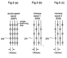
- Figures 3(a)-3(d) are diagrams for explaining the video signal processing by the transmitter in the apparatus according to the second embodiment.
- Figure 4 is a block diagram illustrating a television signal transmitting and receiving apparatus according to a third embodiment of the present invention.
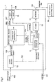
- FIG. 1 is a block diagram illustrating a structure of a receiver (decoder) in a television signal transmitting and receiving apparatus according to a first embodiment of the present invention.
- the decoding coefficient is varied according to the accounting level, whereby the resolution of the decoded image is varied.
- reference numeral 1 designates a video decoder to which a stream 100 specified in MPEG2-System (hereinafter referred to as an MPEG2-System stream) is input.
- Reference numeral 10 designates a system decoder for analyzing the MPEG2-System stream 100 and extracting accounting information 102 and a stream 103 specified in MPEG2-Video (hereinafter referred to as MPEG2-Video stream) from the MPEG2-System stream 100.
- Reference numeral 11 designates an MPEG2-Video decoder including a reverse DCT (Discrete Cosine Transform) operation unit.
- Reference numeral 12 designates an accounting control unit for controlling the accounting level according to an input 101 from the user.
- Reference numeral 13 designates an IC card for totalizing the accounting amounts.
- Reference numeral 14 designates a MODEM (modulator-demodulator) for transmitting accounting amount information 109 output from the IC card 13 through a telephone line to a central station/accounting center 16.
- Reference numeral 15 designates a signal synthesizer circuit for synthesizing a decoded video signal output from the video decoder 11 and an accounting message 105 output from the accounting control unit 12, and outputting a monitor output 108.
- the accounting information 102 and the MPEG2-Video stream 103 which are described in the stream 100, are extracted.
- the MPEG2-System has wide application, including application of MPEG1 system that can multiplexes a plurality of video or audio streams coded individually to produce a single stream (data sequence) as a set of programs, and it is also able to unify a plurality of programs to make a single stream. Therefore, the MPEG2-System is a suitable standard for television broadcasting.
- the accounting information 102 extracted in the system decoder 10 is input to the accounting control unit 12.
- the accounting control unit 12 confirms the accounting level requested by the user (user input 101) and outputs a decoding coefficient control signal 104 according to the accounting level to the reverse DCT operation unit in the MPEG2-Video decoder 11.
- Receiving the decoding coefficient control signal 104, the MPEG2-Video decoder 11 performs decoding (orthogonal transform) of the stream 103 at a level corresponding to the decoding coefficient control signal 104, and outputs a video signal 107.
- the stream 103 is fully decoded when the accounting level is high whereas only a low-frequency component of the stream 103 is decoded when the accounting level is low.
- the accounting control unit 12 always monitors the accounting condition according to the selected accounting level from the accounting information 102 and the user input 101, and outputs the accounting condition, as an accounting message 105, toward the video signal synthesizer 15.
- the video signal synthesizer 15 synthesizes the video signal 107 and the accounting message 105 as occasion demands, and outputs a monitor signal 108.
- the IC card 13 always receives accounting amount signals 106 output from the accounting control unit 12, totalizes the accounting amount signals, and sends accounting amount information 109, which is obtained by totalizing the accounting amount signals for a prescribed period of time, through the MODEM 14 to the central station/accounting center 16.
- the transmission of the accounting amount information 109 would be automatically carried out during a period of time when the telephone line is not crowded, for example, from midnight to early morning.
- a digitally coded television signal such as the MPEG2-Video stream 103
- an accounting level requested by the user is input to the receiver as the user input 101, whereby the decoding coefficient (DCT coefficient) at the decoding in the MPEG2-Video decoder 11 is varied to obtain an image having a resolution according to the accounting level. Therefore, an apparatus and a method for transmitting and receiving television signals that can offer a service with a resolution according to the accounting level are realized.
- decoding of the stream 103 is performed by an operation according to the decoding coefficient which can be set ungradedly, it is possible to set the accounting level ungradedly.
- FIG. 2 is a block diagram illustrating a transmitter (encoder) and a receiver (decoder) in a television signal transmitting and receiving apparatus according to a second embodiment of the present invention.
- reference numeral 20 designates a double-speed camera (525P), called a progressive camera, that can scan a target at a speed twice as high as that of an ordinary camera.
- Reference numeral 21 designates a video signal separator for separating a video signal 202 shot by the double-speed camera 20 into two interlace signals 201 and 202.
- Reference numerals 22 and 23 designate MP@ML encoders for coding the interlace signals 201 and 202 within the standard of MP@ML (Main Profile at Main Level), respectively.
- Reference numeral 24 designates a multiplexer for multiplexing coded signals 203 and 204, and other coded signals 205.
- Reference numeral 25 designates a receiver's side first decoder for low resolution.
- the first decoder 25 comprises a demultiplexer 25a, an MP@ML decoder 25b, and an I-P converter 25c.
- the demultiplexer 25a receives a stream 206 sent from the transmitter, converts the signal included in the stream 206 into signals in the states before the multiplexing, and outputs a coded signal 207 that corresponds to one of the coded signals 203 and 204 which are obtained in the transmitter by encoding the interlace signals 201 and 202 within the MP@ML standard.
- the MP@ML decoder 25b decodes the coded signal 207 output from the demultiplexer 25a and outputs a decoded interlace signal 208.
- the I-P converter 25c converts the decoded interlace signal 208 into a signal 209 for high-resolution and double-speed monitoring.
- Reference numeral 26 designates a receiver's second decoder for high resolution.
- the second decoder 26 comprises a demultiplexer 26a, MP@ML decoders 26b and 26c, and a synthesizer 26d.
- the demultiplexer 26a receives the stream 206 sent from the transmitter, converts the signal included in the stream 206 into signals in the states before the multiplexing, and outputs a coded signal 207 which corresponds to one of the coded signals 203 and 204, and a coded signal 211 which corresponds to the other.
- the MP@ML decoders 26b and 26c decode the coded signals 207 and 211 and outputs decoded interlace signals 212 and 213, respectively.
- the synthesizer 26d synthesizes the decoded interlace signals 212 and 213 and outputs a signal 214 for high-resolution and double-speed monitoring.
- one of the first decoder 25 and the second decoder 26 is selected to decode the stream 206 from the transmitter, in response to an external input signal (not shown) corresponding to the user input 110 described in the first embodiment.
- interlace signals 201 and 202 are coded by the MP@ML encoders 22 and 23, producing coded interlace signals 203 and 204, respectively.
- the multiplexer 24 receives the coded interlace signals 203 and 204 through different channels and also receives other coded signals 205, such as accounting information, and multiplexes these signals to produce a transmission signal 206.
- the transmission signal (video stream) 206 is decoded by one of the first decoder 25 for low resolution and the second decoder 26 for high resolution. More specifically, when the accounting level is low, the transmitted stream 206 is input to the first decoder 25.
- the demultiplexer 25a converts the signal included in the stream 206 into signals in the states before the multiplexing, and outputs a coded signal 207 that corresponds to one of the coded signals 203 and 204 which are respectively produced in the transmitter by coding the interlace signals 201 and 202 within the MP@ML standard.
- the coded signal 207 is input to the MP@ML decoder 25b and decoded to an interlace signal 208.
- the other coded signal i.e., one of the coded signals 203 and 204
- the decoded interlace signal 208 cannot be displayed as it is by the double-speed monitor, it is subjected to, for example, interpolation, by the I-P converter 25c and then it is output as a non-interlace monitor signal 209.
- the transmitted stream 206 is input to the second decoder 26.
- the demultiplexer 26a converts the signal included in the stream 206 into signals in the states before the multiplexing, and outputs coded signals 207 and 211 that respectively correspond to the coded signals 203 and 204 which are produced in the transmitter by coding the interlace signals 201 and 202 within the MP@ML standard.
- coded signals 207 and 211 are input to the MP@ML decoders 26b and 26c and decoded to interlace signals 212 and 213, respectively.
- interlace signals 212 and 213 are input to the synthesizer 26d and synthesized to be a signal equal to the video signal 200 shot by the double-speed camera 20 before separation by the video signal separator 21.
- This video signal is output from the synthesizer 26d as a monitor signal 214.
- the video signal 200 shot by the double-speed camera 20 is converted into two interlace signals 201 and 202, and these interlace signals are coded by the MP@ML encoders 22 and 23, received by the multiplexer 24 through different channels and multiplexed, and transmitted to the decoder (receiver).
- the decoder it is decided according to the accounting level whether both the interlace signals 201 and 202 are decoded or one of the interlace signals is decoded. Therefore, an apparatus and a method for transmitting and receiving television signals, which can offer a service with a resolution according to the accounting level (two grades), are realized.
- EDTV-II has been disclosed in the following publications: Japanese Patent Unexamined Publications Nos. Hei.1-258581, Hei.1-317079, Hei.3-237894, Hei.4-240982, and Hei.7-79420, and Japanese Patent Examined Publications Nos. Hei.1-7555 and Hei.3-52278.
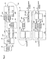
- FIG. 4 is a block diagram illustrating a transmitter (encoder) and a receiver (decoder) in a television signal transmitting and receiving apparatus according to a third embodiment of the invention.
- This third embodiment provides another method for preparing an image of a resolution according to the accounting level when a stream specified in MPEG2-System is coded.
- reference numeral 30 designates a video signal separator for separating a video signal shot by a double-speed camera 20 into an interlace signal 215 of a main picture (Letter Box) in a frequency band that is transmittable by the NTSC system (hereinafter referred to as a main picture signal), and a vertical high-frequency (VH) component 216 and a horizontal high-frequency (HH) component 217 which are not transmittable by the NTSC system.
- Reference numerals 31 and 32 designate high-frequency component folding units for converting the VH and HH components 216 and 217 into low-frequency components, for example, DC level components, using folding method.
- Reference numeral 33 designates a high-frequency component synthesizer for synthesizing the VH and HH components and outputting the synthesized signal as an interlace signal 218 within a frequency band transmittable by the NTSC system.
- Reference numeral 22 designates an MP@ML encoder for coding the main picture signal 215 and outputting a coded signal 219
- reference numeral 23 designates an MP@ML encoder 23 for coding the VH/HH component (interlace) signal 218 and outputting a coded signal 220.
- Reference numeral 24 designates a multiplexer for multiplexing the coded signals 219 and 220 and outputting a stream 221.
- Reference numeral 27 designates a receiver's first decoder for low resolution.
- the first decoder 27 comprises a demultiplexer 27a, an MP@ML decoder 27b, and an I-P converter 27c.
- the demultiplexer 27a receives the stream 221 from the transmitter, converts the signal included in the stream 221 into signals in the states before the multiplexing, and outputs a signal 222 which corresponds to the coded signal 219 obtained in the transmitter by coding the main picture signal 215 within the MP@ML standard.
- the MP@ML decoder 27b decodes the main picture coded signal 222 output from the demultiplexer 27a and outputs a main picture interlace signal 223.
- the I-P converter 27c converts the main picture interlace signal 222 into a signal 224 for high-resolution and double-speed monitoring.
- Reference numeral 28 designates a receiver's second decoder for high resolution.
- the second decoder 28 comprises a demultiplexer 28a, MP@ML decoders 28b and 28c, and a synthesizer 28d.
- the demultiplexer 28a receives the stream 221 sent from the transmitter, converts the signal included in the stream 221 into signals in the states before the multiplexing, and outputs a signal 222 which corresponds to the coded signal 219 obtained in the transmitter by coding the main picture signal 215 within the MP@ML standard, and a signal 225 which corresponds to the coded signal 220 obtained in the transmitter by coding the synthesized VH and HH components, i.e., the interlace signal 218, within the MP@ML standard.
- the MP@ML decoder 28b decodes the main picture coded signal 222 output from the demultiplexer 28a and outputs a main picture interlace signal 223.
- the MP@ML decoder 28c decodes the VH/HH component coded signal 225 output from the demultiplexer 28a and outputs a VH/HH component interlace signal 226.
- the synthesizer 28d synthesises the decoded main picture interlace signals 223 and the decoded VH/HH component interlace signal 226, and outputs a signal 227 for high-resolution and double-speed monitoring.
- one of the first decoder 27 and the second decoder 28 is selected as a decoder to decode the transmitted stream 221, in response to an external input signal (not shown) corresponding to the user input 110 described for the first embodiment.
- the video signal 200 shot by the double-speed camera 20 is input to the video signal separator 30.
- the video signal separator 30 separates the video signal 200 into an interlace signal 215 of a main picture (Letter Box) in a frequency band that is transmittable by the NTSC system, and a vertical high-frequency (VH) component 216 and a horizontal high-frequency (HH) component 217 which are not transmittable by the NTSC system.
- the VH and HH components 216 and 217 are input to the folding units 31 and 32, respectively, wherein these high-frequency components are converted to, for example, DC level components. Thereafter, these VH and HH components are input to the synthesizer 33.
- the synthesizer 33 synthesizes the VH component and the HH component and outputs a high-frequency component (interlace) signal 218.
- the interlace signal 218 and the main picture interlace signal 215 are coded by the MP@ML encoders 23 and 22, respectively, and input to the multiplexer 24.
- the VH/HH component signal 220 which is obtained by folding and encoding the VH and HH components, occupies a frequency band narrower than the frequency band of the interlace signal 219, which is obtained by encoding the main picture signal 215, because the narrow band of the VH/HH component signal 220 does not adversely affect the practical use of the apparatus.
- the multiplexer 24 receives the two coded interlace signals 219 and 220 through different channels and also receives other coded video signals 205 through different channels, and multiplexes these signals to produce a transmission signal 221.
- the transmission signal (stream) 221 is decoded by one of the first decoder 27 for low resolution and the second decoder 28 for high resolution. More specifically, when the accounting level is low, the transmitted stream 221 is input to the first decoder 27.
- the demultiplexer 25a converts the stream 221 into signals in the states before the multiplexing, and outputs a coded signal 222 that corresponds to the coded signal 219 which is produced in the transmitter by coding the main picture signal 215 in the MP@ML standard.
- the coded signal 222 is input to the MP@ML decoder 27b and decoded to an interlace signal 223.
- the interlace signal 223 output from the MP@ML decoder 27b cannot be displayed as it is by the double-speed monitor, it is subjected to, for example, interpolation, by the I-P converter 27c and then it is output as a non-interlace monitor signal 224.
- the transmitted stream 221 is input to the second decoder 28.
- the demultiplexer 28a converts the stream 221 into signals in the states before the multiplexing, and outputs a coded signal 222 that corresponds to the coded signal 219 which is produced in the transmitter by coding the main picture signal 215 in the MP@ML standard, and a coded signal 225 that corresponds to the coded signal 220 which is produced in the transmitter by coding the VH/HH component signal 218 in the MP@ML standard.
- coded signals 222 and 225 are input to the MP@ML decoder 28b and the MP@ML decoder 28c and decoded to interlace signals 223 and 226, respectively.
- the two coded signals 219 and 220 before the multiplexing are decoded to signals of two channels, i.e., the main picture interlace signal 223 and the VH/HH component interlace signal 226, respectively.
- These decoded two-channel interlace signals 223 and 226 are input to the synthesizer 28d and synthesized to be a signal equal to the video signal 200 shot by the double-speed camera 20 before separation by the video signal separator 30.
- This video signal is output from the synthesizer 28d as a monitor signal 227.
- the video signal 200 shot by the double-speed camera 20 is separated into the main picture signal 215 that is transmittable by NTSC and the VH/HH component signals 216 and 217 that are not transmittable by NTSC, and these signals are encoded, multiplexed, and transmitted, through different channels.
- the accounting level On the decoder's side, it is decided according to the accounting level whether both the two channel coded signals are decoded or only the main picture coded signal is decoded. Therefore, an apparatus and a method for transmitting and receiving television signals, which can offer a service with a resolution according to the accounting level (two grades), are realized.
- the apparatus and the method according to this third embodiment are applicable to Wide Clear Vision (EDTV-II) and the like. Further, since an image quality as high as that of an HD television is obtained with two MP@ML decoders utilizing MPEG2, the production cost is reduced as compared with a case where a decoder is fabricated using a memory, such as a DRAM. Further, since the encoded VH/HH component signal 220 occupies less frequency band, judging from the total bit rate, the frequency band used in the apparatus according to this third embodiment is reduced as compared with the second embodiment. Hence, the apparatus according to this third embodiment is superior in multiple channelizing to the apparatus according to the second embodiment.
- EDTV-II Wide Clear Vision
- MP@HL or HP@HL standard which is superior in quality or resolution to the MP@ML standard, may be employed with the same effects as described above.
- An interactive communication system can be constituted using the stream or the channel including the hierarchized additional information.
- Japanese Patent Unexamined Publication No. Hei.7-123375 discloses an interactive communication system.
Abstract
Description
- The present invention relates to a method and an apparatus for transmitting and receiving television signals and, more particularly, to those capable of selecting the grade of received image quality according to the accounting system in chargeable broadcasting employing digital signals.
- In the present television broadcasting, most television images are broadcasted by analog signals. In satellite broadcasting employing the present NTSC (National Television System Committee) system, a transmission speed of 100 Mbps is required, and only one channel can be broadcasted using a transmission band of 27 MHz. On the other hand, a high resolution television, such as a high-grade television, requires a transmission speed of 1.2 Gbps, that is, more than ten times as high as the transmission speed of the NTSC system.
- Accordingly, digital television broadcasting has attracted attention in recent years. For example, when the present NTSC system is compressed to 1/25 using information compressing techniques, required transmission speed is only 4 Mbps, and broadcasts for six channels are possible per the present one channel. In a high-grade television, broadcasting is possible at a transmission speed of about 30 Mbps. In this way, the digital television broadcasting has various advantages over the analog television broadcasting, for example, effective use of electric wave resource, and transmission of high-quality image with less defect.
- On the other hand, chargeable television broadcasting, such as BS, CS, or CATV, has spread in recent years. In the chargeable broadcasting, it is considered to vary the accounting level according to the content of program or the like.
- An object of the present invention is to provide a method and an apparatus for transmitting and receiving television signals, which can provide a service at a resolution or a tone quality according to an accounting system, in digital television broadcasting.
- Other objects and advantages of the invention will become apparent from the detailed description that follows. The detailed description and specific embodiments described are provided only for illustration since various additions and modifications within the scope of the invention will be apparent to those of skill in the art from the detailed description.
- According to a first aspect of the present invention, a television signal transmitting method for transmitting a digitally coded television signal includes the step of transmitting, as the digitally coded television signal, one of a video signal having a resolution and an audio signal having a tone quality, which resolution and tone quality correspond to a decoding coefficient that is input to a receiver by a user.
- According to a second aspect of the present invention, a television signal transmitting apparatus for transmitting a digitally coded television signal comprises an encoding means for transmitting, as the digitally coded television signal, one of a video signal having a resolution and an audio signal having a tone quality, which resolution and tone quality correspond to a decoding coefficient that is input to a receiver by a user.
- According to a third aspect of the present invention, a television signal receiving method for receiving a digitally coded television signal, comprises the steps of variably controlling a decoding coefficient value in response to an external input; and converting the digitally coded television signal into one of a video signal having a resolution according to the controlled decoding coefficient and an audio signal having a quality according to the controlled decoding coefficient.
- According to a fourth aspect of the present invention, the above-mentioned television signal receiving method comprises the steps of storing the variation in the decoding coefficient value, as information, with the lapse of time; and posting the information, for a prescribed period of time, to a base station that sends the television signal.
- According to a fifth aspect of the present invention, a television signal receiving apparatus for receiving a digitally coded television signal, comprises a decoding coefficient control means for variably controlling a decoding coefficient value in response to a user input; and a signal reproducing means for converting the digitally coded television signal into one of a video signal having a resolution according to the controlled-decoding coefficient and an audio signal having a quality according to the controlled decoding coefficient.
- According to a sixth aspect of the present invention, the above-mentioned television signal receiving apparatus comprises means for storing the variation in the decoding coefficient value, as information, with the lapse of time, and posting the information, for a prescribed period of time, to a base station that sends the television signal.
- According to a seventh aspect of the present invention, a television signal transmitting method for transmitting a digitally coded television signal, comprises the steps of separating a video signal into N video signals (N = integer); and coding the N video signals individually and transmitting the coded video signals through different channels.
- According to an eighth aspect of the present invention, in a television signal receiving method for receiving a digitally coded television signal, it is possible to select one of a case where all of coded N video signals (N = integer) are reproduced and a case where some of the N video signals are reproduced, in accordance with an external input.
- According to a ninth aspect of the present invention, a television signal transmitting apparatus for transmitting a digitally coded television signal, comprises a video signal separating means for separating a video signal into N video signals (N = integer); and a video signal encoding means for coding the N video signals individually and transmitting the coded video signals through different channels.
- According to a tenth aspect of the present invention, a television signal receiving apparatus for receiving a digitally coded television signal, comprises a video signal decoding means capable of selecting one of a case where all of coded N video signals (N = integer) are reproduced and a case where some of the N video signals are reproduced, in accordance with an external input.
- According to an eleventh aspect of the present invention, a television signal transmitting method for transmitting a digitally coded television signal, comprises the steps of separating a video signal having a resolution twice as high as an ordinary resolution into two video signals each having the ordinary resolution; and coding the two video signals individually, and transmitting the coded video signals through different channels.
- According to a twelfth aspect of the present invention, in a television signal receiving method for receiving a digitally coded television signal, it is possible to select one of a case where both of two coded video signals, each having an ordinary resolution, are reproduced and a case where one of the coded video signals is reproduced, in accordance with an external input.
- According to a thirteenth aspect of the present invention, a television signal transmitting apparatus for transmitting a digitally coded television signal, comprises a video signal separating means for separating a video signal having a resolution twice as high as an ordinary resolution into two video signals each having the ordinary resolution; and a video signal encoding means for coding the two video signals individually, and transmitting the coded video signals through different channels.
- According to a fourteenth aspect of the present invention, a television signal receiving apparatus for receiving a digitally coded television signal, comprises a video signal decoding means capable of selecting one of a case where both of two coded video signals, each having an ordinary resolution, are reproduced and a case where one of the coded video signals is reproduced, in accordance with an external input.
- According to a fifteenth aspect of the present invention, a television signal transmitting method for transmitting a digitally coded television signal, comprises the steps of separating a video signal having a resolution twice as high as an ordinary resolution into a first video signal comprising high-frequency components and a second video signal comprising components other than the high-frequency components; and coding the first video signal and the second video signal individually, and transmitting the coded first and second video signals through different channels.
- According to a sixteenth aspect of the present invention, in a television signal receiving method for receiving a digitally coded television signal, it is possible to select one of a case where both of a first video signal comprising high-frequency components and a second video signal comprising components other than the high-frequency components, which video signals are obtained by separating a video signal having a resolution twice as high as an ordinary resolution, and a case where one of the first and second video signals is reproduced, in accordance with an external input.
- According to a seventeenth aspect of the present invention, a television signal transmitting apparatus for transmitting a digitally coded television signal, comprises a video signal separating means for separating a video signal having a resolution twice as high as an ordinary resolution into a first video signal comprising high-frequency components and a second video signal comprising components other than the high-frequency components; and a video signal encoding means for encoding the first video signal and the second video signal individually, and transmitting the coded first and second video signals through different channels.
- According to an eighteenth aspect of the present invention, a television signal receiving apparatus for receiving a digitally coded television signal, comprises a video signal decoding means capable of selecting one of a case where both of a first video signal comprising high-frequency components and a second video signal comprising components other than the high-frequency components, which video signals are obtained by separating a video signal having a resolution twice as high as an ordinary resolution, and a case where one of the first and second video signals is reproduced, in accordance with an external input.
- Figure 1 is a block diagram illustrating a television signal transmitting and receiving apparatus according to a first embodiment of the present invention.
- Figure 2 is a block diagram illustrating a television signal transmitting and receiving apparatus according to a second embodiment of the present invention.
- Figures 3(a)-3(d) are diagrams for explaining the video signal processing by the transmitter in the apparatus according to the second embodiment.
- Figure 4 is a block diagram illustrating a television signal transmitting and receiving apparatus according to a third embodiment of the present invention.
- Figure 1 is a block diagram illustrating a structure of a receiver (decoder) in a television signal transmitting and receiving apparatus according to a first embodiment of the present invention. In this first embodiment, when a stream specified in MPEG2-System is decoded, the decoding coefficient is varied according to the accounting level, whereby the resolution of the decoded image is varied. In figure 1,
reference numeral 1 designates a video decoder to which astream 100 specified in MPEG2-System (hereinafter referred to as an MPEG2-System stream) is input.Reference numeral 10 designates a system decoder for analyzing the MPEG2-System stream 100 and extractingaccounting information 102 and astream 103 specified in MPEG2-Video (hereinafter referred to as MPEG2-Video stream) from the MPEG2-System stream 100.Reference numeral 11 designates an MPEG2-Video decoder including a reverse DCT (Discrete Cosine Transform) operation unit.Reference numeral 12 designates an accounting control unit for controlling the accounting level according to aninput 101 from the user.Reference numeral 13 designates an IC card for totalizing the accounting amounts.Reference numeral 14 designates a MODEM (modulator-demodulator) for transmittingaccounting amount information 109 output from theIC card 13 through a telephone line to a central station/accounting center 16.Reference numeral 15 designates a signal synthesizer circuit for synthesizing a decoded video signal output from thevideo decoder 11 and anaccounting message 105 output from theaccounting control unit 12, and outputting amonitor output 108. - A description is given of the operation of the television signal transmitting and receiving apparatus according to the first embodiment. As shown in figure 1, in the
system decoder 10 to which the MPEG2-System stream 100 is input, theaccounting information 102 and the MPEG2-Video stream 103, which are described in thestream 100, are extracted. The MPEG2-System has wide application, including application of MPEG1 system that can multiplexes a plurality of video or audio streams coded individually to produce a single stream (data sequence) as a set of programs, and it is also able to unify a plurality of programs to make a single stream. Therefore, the MPEG2-System is a suitable standard for television broadcasting. - The
accounting information 102 extracted in thesystem decoder 10 is input to theaccounting control unit 12. Theaccounting control unit 12 confirms the accounting level requested by the user (user input 101) and outputs a decodingcoefficient control signal 104 according to the accounting level to the reverse DCT operation unit in the MPEG2-Video decoder 11. Receiving the decodingcoefficient control signal 104, the MPEG2-Video decoder 11 performs decoding (orthogonal transform) of thestream 103 at a level corresponding to the decodingcoefficient control signal 104, and outputs avideo signal 107. To be specific, thestream 103 is fully decoded when the accounting level is high whereas only a low-frequency component of thestream 103 is decoded when the accounting level is low. - The
accounting control unit 12 always monitors the accounting condition according to the selected accounting level from theaccounting information 102 and theuser input 101, and outputs the accounting condition, as anaccounting message 105, toward thevideo signal synthesizer 15. Thevideo signal synthesizer 15 synthesizes thevideo signal 107 and theaccounting message 105 as occasion demands, and outputs amonitor signal 108. TheIC card 13 always receivesaccounting amount signals 106 output from theaccounting control unit 12, totalizes the accounting amount signals, and sendsaccounting amount information 109, which is obtained by totalizing the accounting amount signals for a prescribed period of time, through theMODEM 14 to the central station/accounting center 16. The transmission of theaccounting amount information 109 would be automatically carried out during a period of time when the telephone line is not crowded, for example, from midnight to early morning. - As described above, according to the first embodiment of the invention, a digitally coded television signal, such as the MPEG2-
Video stream 103, is transmitted, and an accounting level requested by the user is input to the receiver as theuser input 101, whereby the decoding coefficient (DCT coefficient) at the decoding in the MPEG2-Video decoder 11 is varied to obtain an image having a resolution according to the accounting level. Therefore, an apparatus and a method for transmitting and receiving television signals that can offer a service with a resolution according to the accounting level are realized. In addition, since decoding of thestream 103 is performed by an operation according to the decoding coefficient which can be set ungradedly, it is possible to set the accounting level ungradedly. - Figure 2 is a block diagram illustrating a transmitter (encoder) and a receiver (decoder) in a television signal transmitting and receiving apparatus according to a second embodiment of the present invention. In this second embodiment, when a stream specified in MPEG2-System is coded, an image having a resolution according to the accounting level is prepared. In figure 2,
reference numeral 20 designates a double-speed camera (525P), called a progressive camera, that can scan a target at a speed twice as high as that of an ordinary camera.Reference numeral 21 designates a video signal separator for separating avideo signal 202 shot by the double-speed camera 20 into twointerlace signals Reference numerals Reference numeral 24 designates a multiplexer for multiplexing codedsignals Reference numeral 25 designates a receiver's side first decoder for low resolution. Thefirst decoder 25 comprises ademultiplexer 25a, anMP@ML decoder 25b, and anI-P converter 25c. Thedemultiplexer 25a receives astream 206 sent from the transmitter, converts the signal included in thestream 206 into signals in the states before the multiplexing, and outputs acoded signal 207 that corresponds to one of the coded signals 203 and 204 which are obtained in the transmitter by encoding the interlace signals 201 and 202 within the MP@ML standard. TheMP@ML decoder 25b decodes the codedsignal 207 output from thedemultiplexer 25a and outputs a decodedinterlace signal 208. TheI-P converter 25c converts the decodedinterlace signal 208 into asignal 209 for high-resolution and double-speed monitoring.Reference numeral 26 designates a receiver's second decoder for high resolution. Thesecond decoder 26 comprises ademultiplexer 26a,MP@ML decoders synthesizer 26d. Thedemultiplexer 26a receives thestream 206 sent from the transmitter, converts the signal included in thestream 206 into signals in the states before the multiplexing, and outputs acoded signal 207 which corresponds to one of the coded signals 203 and 204, and acoded signal 211 which corresponds to the other. The MP@ML decoders 26b and 26c decode the coded signals 207 and 211 and outputs decoded interlace signals 212 and 213, respectively. Thesynthesizer 26d synthesizes the decoded interlace signals 212 and 213 and outputs asignal 214 for high-resolution and double-speed monitoring. In the receiver according to this second embodiment, one of thefirst decoder 25 and thesecond decoder 26 is selected to decode thestream 206 from the transmitter, in response to an external input signal (not shown) corresponding to the user input 110 described in the first embodiment. - A description is given of the operation of the television signal transmitting and receiving apparatus according to this second embodiment.
- Since the
video signal 200 shot by the double-speed camera 20 (refer to figure 3(a)) is not transmittable as it is in the NTSC band, it is separated into two interlace signals 203 (figure 3(b)) and 204 (figure 3(c)). These interlace signals 201 and 202 are coded by theMP@ML encoders multiplexer 24 receives the coded interlace signals 203 and 204 through different channels and also receives othercoded signals 205, such as accounting information, and multiplexes these signals to produce atransmission signal 206. - Although constituents relating to accounting information, such as a system decoder and an accounting control unit as those described for the first embodiment, are not shown in figure 2, in this second embodiment, the operation of receiving the transmission signal by the receiver and separating the accounting information from the transmission signal is identical to the operation performed by the system decoder according to the first embodiment.
- In the receiver, according to the accounting level, the transmission signal (video stream) 206 is decoded by one of the
first decoder 25 for low resolution and thesecond decoder 26 for high resolution. More specifically, when the accounting level is low, the transmittedstream 206 is input to thefirst decoder 25. In thefirst decoder 25, thedemultiplexer 25a converts the signal included in thestream 206 into signals in the states before the multiplexing, and outputs acoded signal 207 that corresponds to one of the coded signals 203 and 204 which are respectively produced in the transmitter by coding the interlace signals 201 and 202 within the MP@ML standard. Thecoded signal 207 is input to theMP@ML decoder 25b and decoded to aninterlace signal 208. In this case, the other coded signal, i.e., one of the coded signals 203 and 204, is not decoded. Since the decodedinterlace signal 208 cannot be displayed as it is by the double-speed monitor, it is subjected to, for example, interpolation, by theI-P converter 25c and then it is output as anon-interlace monitor signal 209. - On the other hand, when the accounting level is high, the transmitted
stream 206 is input to thesecond decoder 26. In thesecond decoder 26, thedemultiplexer 26a converts the signal included in thestream 206 into signals in the states before the multiplexing, and outputs codedsignals MP@ML decoders signals synthesizer 26d and synthesized to be a signal equal to thevideo signal 200 shot by the double-speed camera 20 before separation by thevideo signal separator 21. This video signal is output from thesynthesizer 26d as amonitor signal 214. - As described above, according to the second embodiment of the invention, the
video signal 200 shot by the double-speed camera 20 is converted into twointerlace signals MP@ML encoders multiplexer 24 through different channels and multiplexed, and transmitted to the decoder (receiver). In the decoder, it is decided according to the accounting level whether both the interlace signals 201 and 202 are decoded or one of the interlace signals is decoded. Therefore, an apparatus and a method for transmitting and receiving television signals, which can offer a service with a resolution according to the accounting level (two grades), are realized. Although two channels are completely occupied in the signal transmission, since a resolution as high as that of an HD television is obtained by the signal transmission in the NTSC band, the apparatus and the method according to this second embodiment are applicable to Wide and Clear Vision, i.e., EDTV-II. EDTV-II has been disclosed in the following publications: Japanese Patent Unexamined Publications Nos. Hei.1-258581, Hei.1-317079, Hei.3-237894, Hei.4-240982, and Hei.7-79420, and Japanese Patent Examined Publications Nos. Hei.1-7555 and Hei.3-52278. - Further, since an image quality as high as that of an HD television is obtained with two MP@ML decoders utilizing MPEG2, the production cost is reduced as compared with a case where a decoder is fabricated using a memory, such as a DRAM.
- Figure 4 is a block diagram illustrating a transmitter (encoder) and a receiver (decoder) in a television signal transmitting and receiving apparatus according to a third embodiment of the invention. This third embodiment provides another method for preparing an image of a resolution according to the accounting level when a stream specified in MPEG2-System is coded. In figure 4,
reference numeral 30 designates a video signal separator for separating a video signal shot by a double-speed camera 20 into aninterlace signal 215 of a main picture (Letter Box) in a frequency band that is transmittable by the NTSC system (hereinafter referred to as a main picture signal), and a vertical high-frequency (VH)component 216 and a horizontal high-frequency (HH)component 217 which are not transmittable by the NTSC system.Reference numerals HH components Reference numeral 33 designates a high-frequency component synthesizer for synthesizing the VH and HH components and outputting the synthesized signal as aninterlace signal 218 within a frequency band transmittable by the NTSC system.Reference numeral 22 designates an MP@ML encoder for coding the main picture signal 215 and outputting acoded signal 219, andreference numeral 23 designates anMP@ML encoder 23 for coding the VH/HH component (interlace) signal 218 and outputting acoded signal 220.Reference numeral 24 designates a multiplexer for multiplexing the coded signals 219 and 220 and outputting astream 221.Reference numeral 27 designates a receiver's first decoder for low resolution. Thefirst decoder 27 comprises ademultiplexer 27a, anMP@ML decoder 27b, and anI-P converter 27c. Thedemultiplexer 27a receives thestream 221 from the transmitter, converts the signal included in thestream 221 into signals in the states before the multiplexing, and outputs asignal 222 which corresponds to thecoded signal 219 obtained in the transmitter by coding the main picture signal 215 within the MP@ML standard. TheMP@ML decoder 27b decodes the main picture coded signal 222 output from thedemultiplexer 27a and outputs a main picture interlace signal 223. TheI-P converter 27c converts the main picture interlace signal 222 into asignal 224 for high-resolution and double-speed monitoring.Reference numeral 28 designates a receiver's second decoder for high resolution. Thesecond decoder 28 comprises ademultiplexer 28a,MP@ML decoders synthesizer 28d. Thedemultiplexer 28a receives thestream 221 sent from the transmitter, converts the signal included in thestream 221 into signals in the states before the multiplexing, and outputs asignal 222 which corresponds to thecoded signal 219 obtained in the transmitter by coding the main picture signal 215 within the MP@ML standard, and asignal 225 which corresponds to thecoded signal 220 obtained in the transmitter by coding the synthesized VH and HH components, i.e., theinterlace signal 218, within the MP@ML standard. TheMP@ML decoder 28b decodes the main picture coded signal 222 output from thedemultiplexer 28a and outputs a main picture interlace signal 223. TheMP@ML decoder 28c decodes the VH/HH component coded signal 225 output from thedemultiplexer 28a and outputs a VH/HHcomponent interlace signal 226. Thesynthesizer 28d synthesises the decoded main picture interlace signals 223 and the decoded VH/HHcomponent interlace signal 226, and outputs asignal 227 for high-resolution and double-speed monitoring. In the receiver employed for this third embodiment, one of thefirst decoder 27 and thesecond decoder 28 is selected as a decoder to decode the transmittedstream 221, in response to an external input signal (not shown) corresponding to the user input 110 described for the first embodiment. - The operation of the television signal transmitting and receiving apparatus according to the third embodiment of the invention will be described using figure 4.
- The
video signal 200 shot by the double-speed camera 20 is input to thevideo signal separator 30. Thevideo signal separator 30 separates thevideo signal 200 into aninterlace signal 215 of a main picture (Letter Box) in a frequency band that is transmittable by the NTSC system, and a vertical high-frequency (VH)component 216 and a horizontal high-frequency (HH)component 217 which are not transmittable by the NTSC system. The VH andHH components folding units synthesizer 33. Thesynthesizer 33 synthesizes the VH component and the HH component and outputs a high-frequency component (interlace)signal 218. Theinterlace signal 218 and the main picture interlace signal 215 are coded by theMP@ML encoders multiplexer 24. The VH/HH component signal 220, which is obtained by folding and encoding the VH and HH components, occupies a frequency band narrower than the frequency band of theinterlace signal 219, which is obtained by encoding themain picture signal 215, because the narrow band of the VH/HH component signal 220 does not adversely affect the practical use of the apparatus. Themultiplexer 24 receives the two coded interlace signals 219 and 220 through different channels and also receives other coded video signals 205 through different channels, and multiplexes these signals to produce atransmission signal 221. - Although constituents relating to accounting information, such as a system decoder and an accounting control unit as those described for the first embodiment, are not illustrated in figure 4, also in this third embodiment, the operation of receiving the transmission signal by the receiver and separating the accounting information from the transmission signal is identical to the operation performed by the
system decoder 10 according to the first embodiment. - In the receiver, according to the accounting level, the transmission signal (stream) 221 is decoded by one of the
first decoder 27 for low resolution and thesecond decoder 28 for high resolution. More specifically, when the accounting level is low, the transmittedstream 221 is input to thefirst decoder 27. In thefirst decoder 27, thedemultiplexer 25a converts thestream 221 into signals in the states before the multiplexing, and outputs acoded signal 222 that corresponds to thecoded signal 219 which is produced in the transmitter by coding themain picture signal 215 in the MP@ML standard. Thecoded signal 222 is input to theMP@ML decoder 27b and decoded to aninterlace signal 223. In this case, only the main picture coded signal 219 (one channel) is decoded while the VH/HH component codedsignal 220 is not decoded. Since theinterlace signal 223 output from theMP@ML decoder 27b cannot be displayed as it is by the double-speed monitor, it is subjected to, for example, interpolation, by theI-P converter 27c and then it is output as anon-interlace monitor signal 224. - On the other hand, when the accounting level is high, the transmitted
stream 221 is input to thesecond decoder 28. In thesecond decoder 28, thedemultiplexer 28a converts thestream 221 into signals in the states before the multiplexing, and outputs acoded signal 222 that corresponds to thecoded signal 219 which is produced in the transmitter by coding themain picture signal 215 in the MP@ML standard, and acoded signal 225 that corresponds to thecoded signal 220 which is produced in the transmitter by coding the VH/HH component signal 218 in the MP@ML standard. These coded signals 222 and 225 are input to theMP@ML decoder 28b and theMP@ML decoder 28c and decoded to interlacesignals signals component interlace signal 226, respectively. These decoded two-channel interlace signals 223 and 226 are input to thesynthesizer 28d and synthesized to be a signal equal to thevideo signal 200 shot by the double-speed camera 20 before separation by thevideo signal separator 30. This video signal is output from thesynthesizer 28d as amonitor signal 227. - As described above, according to the third embodiment of the invention, the
video signal 200 shot by the double-speed camera 20 is separated into the main picture signal 215 that is transmittable by NTSC and the VH/HH component signals 216 and 217 that are not transmittable by NTSC, and these signals are encoded, multiplexed, and transmitted, through different channels. On the decoder's side, it is decided according to the accounting level whether both the two channel coded signals are decoded or only the main picture coded signal is decoded. Therefore, an apparatus and a method for transmitting and receiving television signals, which can offer a service with a resolution according to the accounting level (two grades), are realized. Although two channels are completely occupied in the signal transmission, since a resolution as high as that of an HD television is obtained by the signal transmission in the NTSC band, the apparatus and the method according to this third embodiment are applicable to Wide Clear Vision (EDTV-II) and the like. Further, since an image quality as high as that of an HD television is obtained with two MP@ML decoders utilizing MPEG2, the production cost is reduced as compared with a case where a decoder is fabricated using a memory, such as a DRAM. Further, since the encoded VH/HH component signal 220 occupies less frequency band, judging from the total bit rate, the frequency band used in the apparatus according to this third embodiment is reduced as compared with the second embodiment. Hence, the apparatus according to this third embodiment is superior in multiple channelizing to the apparatus according to the second embodiment. - Although in the first to third embodiments of the invention only the image quality is varied according to the accounting level, it is possible to vary the tone quality of reproduced voice according to the accounting level by transmitting signals of different bit rates for voice.
- Although in the second and third embodiments of the invention encoding and decoding are performed in the MP@ML standard, MP@HL or HP@HL standard, which is superior in quality or resolution to the MP@ML standard, may be employed with the same effects as described above.
- Further, although in the first to third embodiments of the invention only two channels are used for one program, it will be possible in future to use multiple (three or more) channels for one program. Then, hierarchization with more stages will be realized, and an accounting according to the hierarchization will be possible.
- Furthermore, it is possible to provide, according to the accounting level, additional information that is hierarchized in an MPEG2-Video stream or a prescribed channel, for example, information of goods relating to the program and offered by the sponsor. An interactive communication system can be constituted using the stream or the channel including the hierarchized additional information. For example, Japanese Patent Unexamined Publication No. Hei.7-123375 discloses an interactive communication system.
Claims (30)
- A television signal transmitting method for transmitting a digitally coded television signal, said method including the step of transmitting, as the digitally coded television signal, one of a video signal having a resolution and an audio signal having a tone quality, which resolution and tone quality correspond to a decoding coefficient that is input to a receiver by a user.
- A television signal transmitting apparatus (Fig.2) for transmitting a digitally coded television signal, comprising an encoding means (22,23) for transmitting, as the digitally coded television signal, one of a video signal having a resolution and an audio signal having a tone quality, which resolution and tone quality correspond to a decoding coefficient that is input to a receiver by a user.
- A television signal receiving method for receiving a digitally coded television signal, comprising the steps of:variably controlling a decoding coefficient value in response to an external input; andconverting the digitally coded television signal into one of a video signal having a resolution according to the controlled decoding coefficient and an audio signal having a tone quality according to the controlled decoding coefficient.
- The television signal receiving method of claim 3 comprising the steps of:storing the variation in the decoding coefficient value, as information, with the lapse of time; andposting the information, for a prescribed period of time, to a base station that sends the television signal.
- A television signal receiving apparatus (Fig.1) for receiving a digitally coded television signal, comprising:a decoding coefficient control means (12) for variably controlling a decoding coefficient value in response to a user input; anda signal reproducing means (11) for converting the digitally coded television signal into one of a video signal having a resolution according to the controlled decoding coefficient and an audio signal having a tone quality according to the controlled decoding coefficient.
- The television signal receiving apparatus of claim 5 comprising:means (13,14) for storing the variation in the decoding coefficient value, as information, with the lapse of time, and posting the information, for a prescribed period of time, to a base station that sends the television signal.
- A television signal transmitting method for transmitting a digitally coded television signal, comprising the steps of:separating a video signal into N video signals (N = integer); andcoding the N video signals individually and transmitting the coded video signals through different channels.
- A television signal receiving method for receiving a digitally coded television signal, wherein it is possible to select one of a case where all of coded N video signals (N = integer) are reproduced and a case where some of the N video signals are reproduced, in accordance with an external input.
- A television signal transmitting apparatus (Fig.2) for transmitting a digitally coded television signal, comprising:a video signal separating means (21) for separating a video signal into N video signals (N = integer); anda video signal encoding means (22,23) for coding the N video signals individually and transmitting the coded video signals through different channels.
- A television signal receiving apparatus (Fig.2) for receiving a digitally coded television signal, comprising a video signal decoding means (25,26) capable of selecting one of a case where all of coded N video signals (N = integer) are reproduced and a case where some of the N video signals are reproduced, in accordance with an external input.
- A television signal transmitting method for transmitting a digitally coded television signal, comprising the steps of:separating a video signal having a resolution twice as high as an ordinary resolution into two video signals each having the ordinary resolution; andcoding the two video signals individually, and transmitting the coded video signals through different channels.
- A television signal receiving method for receiving a digitally coded television signal, wherein it is possible to select one of a case where both of two coded video signals, each having an ordinary resolution, are reproduced and a case where one of the coded video signals is reproduced, in accordance with an external input.
- A television signal transmitting apparatus (Fig.2) for transmitting a digitally coded television signal, comprising:a video signal separating means (21) for separating a video signal having a resolution twice as high as an ordinary resolution into two video signals each having the ordinary resolution; anda video signal encoding means (22,23) for coding the two video signals individually, and transmitting the coded video signals through different channels.
- A television signal receiving apparatus (Fig.2) for receiving a digitally coded television signal, comprising a video signal decoding means (25,26) capable of selecting one of a case where both of two coded video signals, each having an ordinary resolution, are reproduced and a case where one of the coded video signals is reproduced, in accordance with an external input.
- A television signal transmitting method for transmitting a digitally coded television signal, comprising the steps of:separating a video signal having a resolution twice as high as an ordinary resolution into a first video signal comprising high-frequency components and a second video signal comprising components other than the high-frequency components; andcoding the first video signal and the second video signal individually, and transmitting the coded first and second video signals through different channels.
- A television signal receiving method for receiving a digitally coded television signal, wherein it is possible to select one of a case where both of a first video signal comprising high-frequency components and a second video signal comprising components other than the high-frequency components, which video signals are obtained by separating a video signal having a resolution twice as high as an ordinary resolution, and a case where one of the first and second video signals is reproduced, in accordance with an external input.
- A television signal transmitting apparatus (Fig.4) for transmitting a digitally coded television signal, comprising:a video signal separating means (30) for separating a video signal having a resolution twice as high as an ordinary resolution into a first video signal comprising high-frequency components and a second video signal comprising components other than the high-frequency components; anda video signal encoding means (22,23) for encoding the first video signal and the second video signal individually, and transmitting the coded first and second video signals through different channels.
- A television signal receiving apparatus (Fig.4) for receiving a digitally coded television signal, comprising a video signal decoding means (27,28) capable of selecting one of a case where both of a first video signal comprising high-frequency components and a second video signal comprising components other than the high-frequency components, which video signals are obtained by separating a video signal having a resolution twice as high as an ordinary resolution, and a case where one of the first and second video signals is reproduced, in accordance with an external input.
- A television signal transmitting method for transmitting a digitally coded television signal, comprising the steps of:separating an audio signal into N audio signals (N = integer); andcoding the N audio signals individually and transmitting the coded audio signals through different channels.
- A television signal receiving method for receiving a digitally coded television signal, wherein it is possible to select one of a case where all of coded N audio signals (N = integer) are reproduced and a case where some of the N audio signals are reproduced, in accordance with an external input.
- A television signal transmitting apparatus for transmitting a digitally coded television signal, comprising:an audio signal separating means for separating an audio signal into N audio signals (N = integer); andan audio signal encoding means for coding the N audio signals individually and transmitting the coded audio signals through different channels.
- A television signal receiving apparatus for receiving a digitally coded television signal, comprising an audio signal decoding means capable of selecting one of a case where all of coded N audio signals (N = integer) are reproduced and a case where some of the N audio signals are reproduced, in accordance with an external input.
- A television signal transmitting method for transmitting a digitally coded television signal, comprising the steps of:separating an audio signal having a tone quality higher than an ordinary tone quality into two audio signals each having the ordinary tone quality; andcoding the two audio signals individually, and transmitting the coded audio signals through different channels.
- A television signal receiving method for receiving a digitally coded television signal, wherein it is possible to select one of a case where both of two coded audio signals, each having an ordinary tone quality, are reproduced and a case where one of the coded audio signals is reproduced, in accordance with an external input.
- A television signal transmitting apparatus for transmitting a digitally coded television signal, comprising:an audio signal separating means for separating an audio signal having a tone quality higher than an ordinary tone quality into two audio signals each having the ordinary tone quality; andan audio signal encoding means for coding the two audio signals individually, and transmitting the coded audio signals through different channels.
- A television signal receiving apparatus for receiving a digitally coded television signal, comprising an audio signal decoding means capable of selecting one of a case where both of two coded audio signals, each having an ordinary tone quality, are reproduced and a case where one of the coded audio signals is reproduced, in accordance with an external input.
- A television signal transmitting method for transmitting a digitally coded television signal, comprising the steps of:separating an audio signal having a tone quality higher than an ordinary tone quality into a first audio signal having a relatively high bit rate and a second audio signal having a relatively low bit rate; andcoding the first audio signal and the second audio signal individually, and transmitting the coded first and second audio signals through different channels.
- A television signal receiving method for receiving a digitally coded television signal, wherein it is possible to select one of a case where both of a first audio signal having a relatively high bit rate and a second audio signal having a relatively low bit rate, which audio signals are obtained by separating an audio signal having a tone quality higher than an ordinary tone quality, and a case where one of the first and second audio signals is reproduced, in accordance with an external input.
- A television signal transmitting apparatus for transmitting a digitally coded television signal, comprising:an audio signal separating means for separating an audio signal having a tone quality higher than an ordinary tone quality into a first audio signal having a relatively high bit rate and a second audio signal having a relatively low bit rate; andan audio signal encoding means for encoding the first audio signal and the second audio signal individually, and transmitting the coded first and second audio signals through different channels.
- A television signal receiving apparatus for receiving a digitally coded television signal, comprising an audio signal decoding means capable of selecting one of a case where both of a first audio signal having a relatively high bit rate and a second audio signal having a relatively low bit rate, which audio signals are obtained by separating an audio signal having a tone quality higher than an ordinary tone quality, and a case where one of the first and second audio signals is reproduced, in accordance with an external input.
Applications Claiming Priority (3)
| Application Number | Priority Date | Filing Date | Title |
|---|---|---|---|
| JP1156196 | 1996-01-26 | ||
| JP11561/96 | 1996-01-26 | ||
| JP1156196A JPH09205630A (en) | 1996-01-26 | 1996-01-26 | Television signal transmission reception method and television signal transmitter receiver |
Publications (3)
| Publication Number | Publication Date |
|---|---|
| EP0785686A2 true EP0785686A2 (en) | 1997-07-23 |
| EP0785686A3 EP0785686A3 (en) | 1998-04-01 |
| EP0785686B1 EP0785686B1 (en) | 2004-06-16 |
Family
ID=11781358
Family Applications (1)
| Application Number | Title | Priority Date | Filing Date |
|---|---|---|---|
| EP19970100847 Expired - Lifetime EP0785686B1 (en) | 1996-01-26 | 1997-01-21 | Method and apparatus for transmitting and receiving television signal |
Country Status (7)
| Country | Link |
|---|---|
| US (1) | US6345388B1 (en) |
| EP (1) | EP0785686B1 (en) |
| JP (1) | JPH09205630A (en) |
| KR (1) | KR100260287B1 (en) |
| CN (2) | CN1251501C (en) |
| DE (1) | DE69729493T2 (en) |
| TW (1) | TW330365B (en) |
Cited By (6)
| Publication number | Priority date | Publication date | Assignee | Title |
|---|---|---|---|---|
| WO2001041444A1 (en) * | 1999-12-03 | 2001-06-07 | Thomson Licensing S.A. | An adaptive video image information processing system |
| WO2001067743A2 (en) * | 2000-03-08 | 2001-09-13 | Koninklijke Philips Electronics N.V. | Business model for leasing storage space on a digital recorder |
| WO2001078395A1 (en) * | 2000-04-06 | 2001-10-18 | Koninklijke Philips Electronics N.V. | Object-conditional access system |
| EP1170882A2 (en) * | 2000-07-07 | 2002-01-09 | Hitachi, Ltd. | Base station apparatus, mobile station, and contents provider |
| EP1661401A1 (en) * | 2003-07-15 | 2006-05-31 | Citipati Partners, LLC | Method and system for delivering media data |
| US7071995B1 (en) | 1999-05-28 | 2006-07-04 | Thomson Licensing | Adaptive video image information processing system |
Families Citing this family (14)
| Publication number | Priority date | Publication date | Assignee | Title |
|---|---|---|---|---|
| JP3647305B2 (en) | 1999-02-26 | 2005-05-11 | キヤノン株式会社 | Image display device control system and image display system control method |
| US7057667B1 (en) * | 1999-02-26 | 2006-06-06 | Canon Kabushiki Kaisha | Image display control system and method allowing connection of various kinds of image displays to one supply source |
| DE60023968T2 (en) | 1999-02-26 | 2006-06-22 | Canon K.K. | System for controlling a picture display device and method for controlling a picture display system |
| US6788311B1 (en) * | 1999-04-28 | 2004-09-07 | Intel Corporation | Displaying data on lower resolution displays |
| KR100335441B1 (en) * | 1999-05-01 | 2002-05-04 | 윤종용 | Multiplexing video decoding apparatus and method |
| US6756921B2 (en) | 2000-12-27 | 2004-06-29 | Mitsubishi Denki Kabushiki Kaisha | Multiple quality data creation encoder, multiple quality data creation decoder, multiple quantity data encoding decoding system, multiple quality data creation encoding method, multiple quality data creation decoding method, and multiple quality data creation encoding/decoding method |
| US7099951B2 (en) * | 2001-05-24 | 2006-08-29 | Vixs, Inc. | Method and apparatus for multimedia system |
| FR2838589B1 (en) * | 2002-04-10 | 2005-03-04 | Thomson Licensing Sa | DATA TRANSMISSION DEVICE AND DATA RECEIVING DEVICE |
| JP2004112261A (en) * | 2002-09-18 | 2004-04-08 | Fujitsu Ltd | Receiver of digital broadcast program in response to profile of receiver and charging method thereof |
| FR2850826B1 (en) * | 2003-02-04 | 2005-04-01 | Medialive | PROTECTIVE METHOD AND DEVICE FOR SECURE DIFFUSION OF AUDIOVISUAL WORKS |
| CN1333596C (en) * | 2004-06-30 | 2007-08-22 | 大唐电信科技股份有限公司光通信分公司 | Grading device and method for request information and gradidng system and method for requst information |
| JP2007053554A (en) | 2005-08-17 | 2007-03-01 | Sony Corp | Device and method for encoding, device and method for decoding, and program |
| US10154309B2 (en) * | 2014-08-22 | 2018-12-11 | Netflix, Inc. | Dynamically adjusting video merchandising to reflect user preferences |
| WO2018101514A1 (en) * | 2016-12-01 | 2018-06-07 | 엘지전자 주식회사 | Image display device and image display system comprising same |
Citations (8)
| Publication number | Priority date | Publication date | Assignee | Title |
|---|---|---|---|---|
| JPS647555B2 (en) | 1986-11-25 | 1989-02-09 | Hitachi Ltd | |
| JPH01258581A (en) | 1988-04-08 | 1989-10-16 | Hitachi Ltd | Transmitting system for television signal |
| JPH01317079A (en) | 1988-06-17 | 1989-12-21 | Hitachi Ltd | Television signal system |
| JPH0352278A (en) | 1989-07-20 | 1991-03-06 | Fanuc Ltd | Nc laser device |
| JPH03237894A (en) | 1990-02-14 | 1991-10-23 | Sharp Corp | Television signal transmission system |
| JPH04240982A (en) | 1991-01-25 | 1992-08-28 | Hitachi Ltd | Television signal transmitter-receiver |
| JPH0779420A (en) | 1993-09-08 | 1995-03-20 | Hitachi Ltd | Television reinforce signal system |
| JPH07123375A (en) | 1993-10-22 | 1995-05-12 | Matsushita Electric Ind Co Ltd | Character graphic transmission system |
Family Cites Families (9)
| Publication number | Priority date | Publication date | Assignee | Title |
|---|---|---|---|---|
| JPS647555A (en) | 1987-06-30 | 1989-01-11 | Oki Electric Ind Co Ltd | Semiconductor device and manufacture thereof |
| JPH01258851A (en) | 1988-04-08 | 1989-10-16 | Kawasaki Steel Corp | Method for preheating refractory for bidirectional drawing type horizontal continuous casting machine |
| FR2660139B1 (en) * | 1990-03-23 | 1995-08-25 | France Etat | ENCODING AND TRANSMISSION METHOD FOR AT LEAST TWO QUALITY LEVELS OF DIGITAL IMAGES BELONGING TO A SEQUENCE OF IMAGES, AND CORRESPONDING DEVICES. |
| US5235420A (en) * | 1991-03-22 | 1993-08-10 | Bell Communications Research, Inc. | Multilayer universal video coder |
| US5253058A (en) * | 1992-04-01 | 1993-10-12 | Bell Communications Research, Inc. | Efficient coding scheme for multilevel video transmission |
| JPH0622215A (en) * | 1992-07-06 | 1994-01-28 | Toshiba Corp | Video transmission method, video transmitter and video receiver used for the same |
| US5355162A (en) * | 1993-07-13 | 1994-10-11 | Pacific Ray Video Limited | Multi-standard cable television system |
| US6275988B1 (en) * | 1995-06-30 | 2001-08-14 | Canon Kabushiki Kaisha | Image transmission apparatus, image transmission system, and communication apparatus |
| US5748903A (en) * | 1995-07-21 | 1998-05-05 | Intel Corporation | Encoding images using decode rate control |
-
1996
- 1996-01-26 JP JP1156196A patent/JPH09205630A/en active Pending
-
1997
- 1997-01-21 DE DE1997629493 patent/DE69729493T2/en not_active Expired - Fee Related
- 1997-01-21 EP EP19970100847 patent/EP0785686B1/en not_active Expired - Lifetime
- 1997-01-23 CN CNB971029199A patent/CN1251501C/en not_active Expired - Fee Related
- 1997-01-23 CN CNA2005100927723A patent/CN1728820A/en active Pending
- 1997-01-24 TW TW086100770A patent/TW330365B/en not_active IP Right Cessation
- 1997-01-24 US US08/787,746 patent/US6345388B1/en not_active Expired - Fee Related
- 1997-01-25 KR KR1019970002180A patent/KR100260287B1/en not_active IP Right Cessation
Patent Citations (8)
| Publication number | Priority date | Publication date | Assignee | Title |
|---|---|---|---|---|
| JPS647555B2 (en) | 1986-11-25 | 1989-02-09 | Hitachi Ltd | |
| JPH01258581A (en) | 1988-04-08 | 1989-10-16 | Hitachi Ltd | Transmitting system for television signal |
| JPH01317079A (en) | 1988-06-17 | 1989-12-21 | Hitachi Ltd | Television signal system |
| JPH0352278A (en) | 1989-07-20 | 1991-03-06 | Fanuc Ltd | Nc laser device |
| JPH03237894A (en) | 1990-02-14 | 1991-10-23 | Sharp Corp | Television signal transmission system |
| JPH04240982A (en) | 1991-01-25 | 1992-08-28 | Hitachi Ltd | Television signal transmitter-receiver |
| JPH0779420A (en) | 1993-09-08 | 1995-03-20 | Hitachi Ltd | Television reinforce signal system |
| JPH07123375A (en) | 1993-10-22 | 1995-05-12 | Matsushita Electric Ind Co Ltd | Character graphic transmission system |
Cited By (16)
| Publication number | Priority date | Publication date | Assignee | Title |
|---|---|---|---|---|
| US7071995B1 (en) | 1999-05-28 | 2006-07-04 | Thomson Licensing | Adaptive video image information processing system |
| US7538819B2 (en) | 1999-12-03 | 2009-05-26 | Thomson Licensing | Adaptive video image information processing system |
| US7116375B2 (en) | 1999-12-03 | 2006-10-03 | Thomson Licensing | Adaptive video image information processing system |
| WO2001041444A1 (en) * | 1999-12-03 | 2001-06-07 | Thomson Licensing S.A. | An adaptive video image information processing system |
| WO2001067743A2 (en) * | 2000-03-08 | 2001-09-13 | Koninklijke Philips Electronics N.V. | Business model for leasing storage space on a digital recorder |
| WO2001067743A3 (en) * | 2000-03-08 | 2002-01-03 | Koninkl Philips Electronics Nv | Business model for leasing storage space on a digital recorder |
| US6658663B1 (en) | 2000-03-08 | 2003-12-02 | Koninklijke Philips Electronics N.V. | Business model for leasing storage on a digital recorder |
| WO2001078395A1 (en) * | 2000-04-06 | 2001-10-18 | Koninklijke Philips Electronics N.V. | Object-conditional access system |
| EP1686705A3 (en) * | 2000-07-07 | 2006-09-13 | Hitachi, Ltd. | Mobile station |
| EP1686705A2 (en) * | 2000-07-07 | 2006-08-02 | Hitachi, Ltd. | Mobile station |
| US7006484B2 (en) | 2000-07-07 | 2006-02-28 | Hitachi, Ltd. | Base station apparatus, mobile station, and contents provider |
| EP1170882A3 (en) * | 2000-07-07 | 2004-08-04 | Hitachi, Ltd. | Base station apparatus, mobile station, and contents provider |
| EP1170882A2 (en) * | 2000-07-07 | 2002-01-09 | Hitachi, Ltd. | Base station apparatus, mobile station, and contents provider |
| US7561557B2 (en) | 2000-07-07 | 2009-07-14 | Hitachi, Ltd. | Base station apparatus, mobile station, and contents provider |
| EP1661401A1 (en) * | 2003-07-15 | 2006-05-31 | Citipati Partners, LLC | Method and system for delivering media data |
| EP1661401A4 (en) * | 2003-07-15 | 2006-08-02 | Citipati Partners Llc | Method and system for delivering media data |
Also Published As
| Publication number | Publication date |
|---|---|
| EP0785686A3 (en) | 1998-04-01 |
| EP0785686B1 (en) | 2004-06-16 |
| TW330365B (en) | 1998-04-21 |
| JPH09205630A (en) | 1997-08-05 |
| CN1251501C (en) | 2006-04-12 |
| KR970060952A (en) | 1997-08-12 |
| DE69729493T2 (en) | 2005-06-30 |
| CN1168601A (en) | 1997-12-24 |
| CN1728820A (en) | 2006-02-01 |
| DE69729493D1 (en) | 2004-07-22 |
| US6345388B1 (en) | 2002-02-05 |
| KR100260287B1 (en) | 2000-07-01 |
Similar Documents
| Publication | Publication Date | Title |
|---|---|---|
| US6345388B1 (en) | Method and apparatus for transmitting and receiving television signal | |
| US5493339A (en) | System and method for transmitting a plurality of digital services including compressed imaging services and associated ancillary data services | |
| EP0536628B1 (en) | Selection of compressed television signals from single channel allocation based on viewer characteristics | |
| CN1306796C (en) | Decoder device and receiver using the same | |
| EP0928116A2 (en) | Error correction encoding method and apparatus, data transmission method, receiving method and receiver | |
| KR100326641B1 (en) | Methods of transmitting, encoding and decoding video signals, and recording and playback of devices and optical discs | |
| JPH10224751A (en) | Communication of vbi data in digital television data stream | |
| JP2001501400A (en) | Television receiver with integrated receiver and decoder | |
| US5459514A (en) | Video-signal transmitting and receiving apparatus and method for transmitting and receiving high-resolution and low-resolution television signals | |
| EP1182877A2 (en) | Sending progressive video sequences | |
| US5861905A (en) | Digital television system with artificial intelligence | |
| JP2001527351A (en) | Apparatus and method for low noise encoding / decoding | |
| EP1434437A2 (en) | Multimedia recording apparatus with variable compression | |
| EP0851656A1 (en) | System and method for high resolution video compression by tiling | |
| JP2001044866A (en) | Information reception method and system thereof | |
| JP3033702B2 (en) | Transmission device | |
| EP0938233A2 (en) | A method and apparatus for transmitting digital picture signals | |
| JP2000299854A (en) | Multi-channel video audio signal server and program recording medium | |
| JPH10112857A (en) | Method and device for coding and decoding image signal | |
| Kanatsugu et al. | Development of MUSE family systems | |
| Hoffman | Communications—Broadcasting Applications | |
| Netravali et al. | High Definition Television | |
| JPH0722385B2 (en) | Narrow-band multiplex subsample transmitter and transmitter / receiver |
Legal Events
| Date | Code | Title | Description |
|---|---|---|---|
| PUAI | Public reference made under article 153(3) epc to a published international application that has entered the european phase |
Free format text: ORIGINAL CODE: 0009012 |
|
| AK | Designated contracting states |
Kind code of ref document: A2 Designated state(s): DE FR GB |
|
| PUAL | Search report despatched |
Free format text: ORIGINAL CODE: 0009013 |
|
| AK | Designated contracting states |
Kind code of ref document: A3 Designated state(s): DE FR GB |
|
| 17P | Request for examination filed |
Effective date: 19980518 |
|
| 17Q | First examination report despatched |
Effective date: 20000912 |
|
| GRAP | Despatch of communication of intention to grant a patent |
Free format text: ORIGINAL CODE: EPIDOSNIGR1 |
|
| RAP1 | Party data changed (applicant data changed or rights of an application transferred) |
Owner name: MATSUSHITA ELECTRIC INDUSTRIAL CO., LTD. |
|
| GRAS | Grant fee paid |
Free format text: ORIGINAL CODE: EPIDOSNIGR3 |
|
| GRAA | (expected) grant |
Free format text: ORIGINAL CODE: 0009210 |
|
| AK | Designated contracting states |
Kind code of ref document: B1 Designated state(s): DE FR GB |
|
| REG | Reference to a national code |
Ref country code: GB Ref legal event code: FG4D |
|
| REF | Corresponds to: |
Ref document number: 69729493 Country of ref document: DE Date of ref document: 20040722 Kind code of ref document: P |
|
| ET | Fr: translation filed | ||
| PLBE | No opposition filed within time limit |
Free format text: ORIGINAL CODE: 0009261 |
|
| STAA | Information on the status of an ep patent application or granted ep patent |
Free format text: STATUS: NO OPPOSITION FILED WITHIN TIME LIMIT |
|
| 26N | No opposition filed |
Effective date: 20050317 |
|
| PGFP | Annual fee paid to national office [announced via postgrant information from national office to epo] |
Ref country code: FR Payment date: 20060110 Year of fee payment: 10 |
|
| PGFP | Annual fee paid to national office [announced via postgrant information from national office to epo] |
Ref country code: DE Payment date: 20060119 Year of fee payment: 10 |
|
| PG25 | Lapsed in a contracting state [announced via postgrant information from national office to epo] |
Ref country code: DE Free format text: LAPSE BECAUSE OF NON-PAYMENT OF DUE FEES Effective date: 20070801 |
|
| GBPC | Gb: european patent ceased through non-payment of renewal fee |
Effective date: 20070121 |
|
| REG | Reference to a national code |
Ref country code: FR Ref legal event code: ST Effective date: 20070930 |
|
| PG25 | Lapsed in a contracting state [announced via postgrant information from national office to epo] |
Ref country code: GB Free format text: LAPSE BECAUSE OF NON-PAYMENT OF DUE FEES Effective date: 20070121 |
|
| PG25 | Lapsed in a contracting state [announced via postgrant information from national office to epo] |
Ref country code: FR Free format text: LAPSE BECAUSE OF NON-PAYMENT OF DUE FEES Effective date: 20070131 |
|
| PGFP | Annual fee paid to national office [announced via postgrant information from national office to epo] |
Ref country code: GB Payment date: 20060118 Year of fee payment: 10 |