EP0784085A2 - Ink composition, pattern forming method, and colour filter - Google Patents
Ink composition, pattern forming method, and colour filter Download PDFInfo
- Publication number
- EP0784085A2 EP0784085A2 EP97300128A EP97300128A EP0784085A2 EP 0784085 A2 EP0784085 A2 EP 0784085A2 EP 97300128 A EP97300128 A EP 97300128A EP 97300128 A EP97300128 A EP 97300128A EP 0784085 A2 EP0784085 A2 EP 0784085A2
- Authority
- EP
- European Patent Office
- Prior art keywords
- pigment
- solvent
- ink composition
- black
- base material
- Prior art date
- Legal status (The legal status is an assumption and is not a legal conclusion. Google has not performed a legal analysis and makes no representation as to the accuracy of the status listed.)
- Granted
Links
Images
Classifications
-
- C—CHEMISTRY; METALLURGY
- C09—DYES; PAINTS; POLISHES; NATURAL RESINS; ADHESIVES; COMPOSITIONS NOT OTHERWISE PROVIDED FOR; APPLICATIONS OF MATERIALS NOT OTHERWISE PROVIDED FOR
- C09D—COATING COMPOSITIONS, e.g. PAINTS, VARNISHES OR LACQUERS; FILLING PASTES; CHEMICAL PAINT OR INK REMOVERS; INKS; CORRECTING FLUIDS; WOODSTAINS; PASTES OR SOLIDS FOR COLOURING OR PRINTING; USE OF MATERIALS THEREFOR
- C09D11/00—Inks
- C09D11/30—Inkjet printing inks
- C09D11/32—Inkjet printing inks characterised by colouring agents
- C09D11/322—Pigment inks
-
- B—PERFORMING OPERATIONS; TRANSPORTING
- B41—PRINTING; LINING MACHINES; TYPEWRITERS; STAMPS
- B41J—TYPEWRITERS; SELECTIVE PRINTING MECHANISMS, i.e. MECHANISMS PRINTING OTHERWISE THAN FROM A FORME; CORRECTION OF TYPOGRAPHICAL ERRORS
- B41J2/00—Typewriters or selective printing mechanisms characterised by the printing or marking process for which they are designed
- B41J2/005—Typewriters or selective printing mechanisms characterised by the printing or marking process for which they are designed characterised by bringing liquid or particles selectively into contact with a printing material
- B41J2/01—Ink jet
-
- C—CHEMISTRY; METALLURGY
- C09—DYES; PAINTS; POLISHES; NATURAL RESINS; ADHESIVES; COMPOSITIONS NOT OTHERWISE PROVIDED FOR; APPLICATIONS OF MATERIALS NOT OTHERWISE PROVIDED FOR
- C09D—COATING COMPOSITIONS, e.g. PAINTS, VARNISHES OR LACQUERS; FILLING PASTES; CHEMICAL PAINT OR INK REMOVERS; INKS; CORRECTING FLUIDS; WOODSTAINS; PASTES OR SOLIDS FOR COLOURING OR PRINTING; USE OF MATERIALS THEREFOR
- C09D11/00—Inks
- C09D11/30—Inkjet printing inks
- C09D11/36—Inkjet printing inks based on non-aqueous solvents
-
- G—PHYSICS
- G02—OPTICS
- G02B—OPTICAL ELEMENTS, SYSTEMS OR APPARATUS
- G02B5/00—Optical elements other than lenses
- G02B5/20—Filters
- G02B5/201—Filters in the form of arrays
Definitions
- the present invention relates to an ink composition, a pattern forming method and a color filter, and particularly to an ink composition used to form a pattern by an ink-jet method, a pattern forming method which uses the above ink composition, and a color filter which is produced by the pattern forming method using the above ink composition.
- the pattern forming method according to the ink-jet method sprays droplets of an ink composition onto a base material by various types of ink composition ejecting methods such as an electrostatic attraction method, a method which employs a piezoelectric element to mechanically vibrate or bias ink, or a method of heating to foam ink and using a pressure by the foamed ink to form a pattern on the surface of the base material.
- the pattern forming method according to the ink-jet method has advantages that a pattern can be formed quickly without involving production of large noise, and a multi-colored pattern can be formed easily. Therefore, it is attracting attention in many fields.
- color filters which are used for display units such as a CRT, a liquid crystal display and a plasma display, or a solid state image pickup device and the like have been produced by various types of methods such as a pigment dispersion method, a dye dispersion method, and a dyeing method.
- Japanese Patent Laid-Open Publication No. Hei 7-179711 describes a method of producing a fluorescent film with a filter by forming a patterned photo absorption layer on the inner face of a face plate, applying a pigment dispersed solution and a phosphor slurry, and exposing through a mask and developing.
- Japanese Patent Laid-Open Publication No. Sho 59-75205 describes a method of producing a color filter by forming a colored layer on a substrate by the ink-jet method.
- the method of producing a fluorescent film with a filter described in Japanese Patent Laid-Open Publication No. Hei 7-179711 has a disadvantage that the production cost is high because it involves many steps to produce the fluorescent film, and the application of a pigment dispersed solution and a phosphor slurry and the exposure through a mask and development are required for each color.
- the method of producing a color filter described in Japanese Patent Laid-Open Publication No. Sho 59-75205 which forms a colored layer on a substrate by the ink-jet method has disadvantages that a dispersion preventive pattern or a wettability improver must be formed on a glass substrate in advance, increasing facilities investment and the number of processes, also increasing the production cost, and lowering a production yield.
- the present invention has been completed in view of the above circumstances, and aims to provide an ink composition which can form a fine pattern on the surface of glass, ceramics or polyester resins by the ink-jet method without requiring to form a wettability improver.
- the present invention also aims to provide a pattern forming method which can easily form a fine pattern efficiently on the surface of a glass substrate or the like, and does not involve many processes or facilities investment, so that the formed pattern excels in reliability and economy.
- the present invention aims to provide a color filter having a pattern which excels in optical resistance and water resistance and has high reliability in practical use, and which also excels in economy.
- An ink composition according to the present invention is controlled to keep maximum the ratio (V/S) of the volume (V) of a system which consists of a solvent, a pigment dispersed into the solvent and a dispersant which is dispersed into the solvent to enhance an affinity between the solvent and the pigment; and the surface area (S) of an interface of the system produced on a boundary between the system and a gas phase.
- an ink composition according to the present invention may have a system which includes or consists of a solvent, a pigment dispersed into the solvent and a dispersant which is dispersed into the solvent to enhance an affinity between the solvent and the pigment, and the system has (1) a surface tension of 20.0 dyn/cm to 50.0 dyn/cm at 25°C, and (2) a viscosity of 1.5 cp to 20.0 cp at 25°C.
- an ink composition according to the present invention may contain a solvent, a pigment dispersed into the solvent, a dispersant which is dispersed into the solvent to enhance an affinity between the solvent and the pigment, and an additive which is dispersed into the solvent to control free energy of an interface.
- a pattern forming method has a step of ejecting from a nozzle by an ink-jet method droplets of an ink composition of which the ratio (V/S) between the volume (V) of a system which consists of a solvent, a pigment dispersed into the solvent and a dispersant which is dispersed into the solvent to enhance the affinity between the solvent and the pigment; and the surface area (S) of the interface of the system produced on at the boundary between the system and a gas phase is controlled to be kept at a maximum, a step of adhering the droplets onto the surface of a base material, and a step of adhering the pigment contained in the droplets onto the base material.
- a pattern forming method has a step of ejecting from a nozzle by an ink-jet method droplets of an ink composition having a system which consists of a solvent, a pigment dispersed into the solvent and a dispersant which is dispersed into the solvent to enhance an affinity between the solvent and the pigment, and which has (1) a surface tension of 20.0 dyn/cm to 50.0 dyn/cm at 25°C and (2) a viscosity of 1.5 cp to 20.0 cp at 25°C, a step of adhering the droplets onto the surface of a base material, and a step of adhering the pigment contained in the droplets onto the base material.
- a pattern forming method has a step of ejecting from a nozzle by an ink-jet method droplets of an ink composition containing a solvent, a pigment dispersed into the solvent, a dispersant which is dispersed into the solvent to enhance an affinity between the solvent and the pigment, and an additive which is dispersed into the solvent to control free energy of an interface, a step of adhering the droplets onto the surface of a base material, and a step of adhering the pigment contained in the droplets onto the base material.
- a color filter according to the invention has a base material and a colored layer which is formed of a pigment adhered to the surface of the base material by an ink-jet method.
- a conventional ink composition is not adequately adhered to the surface of such a base material, and the ink composition is repelled or spreads on the surface of the base material. And, since the adhesion of a coloring matter to the surface of the base material is weak, it is easily separated from the surface of the base material, and the formed pattern is broken in a short period.
- the base material used herein generally means those having a to-be-colored layer surface, onto which the coloring matter of the ink composition is adhered, with a structure of glass, ceramics or a film made of polyester resin or the like which is different from fiber of paper or the like. Therefore, the base materials belonging to such a category can be a glass substrate or a ceramics substrate; various types of film materials such as polyester resin, diacetate resin, triacetate resin, acrylic resin, polycarbonate resin, polyvinyl chloride resin, polyimide resin, cellophane or celluloid; and coated paper of which the surface is coated with organic polymer compounds such as polyamide or polyester.
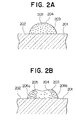
- Fig. 2A and Fig. 2B are schematic views showing a process that an ink composition is adhered to the surface of a base material such as a glass substrate or ceramics substrate and a solvent evaporates from a droplet of the ink composition.
- the surface area (S) of an interface 204, which is in contact with a gas phase, of the ink composition 203 is kept to have the minimum ratio (S/V) to the volume (V) of the ink composition 203, in other words, the ratio (V/S) between the volume (V) of the ink composition 203 and the surface area (S) of the interface 204 is controlled to be kept at a maximum as shown in Fig. 2A.
- the minimum ratio between the surface area of the interface 204, which is in contact with the gas phase, of the ink composition 203 and the volume of the ink composition 203 cannot be kept, and the ratio of the surface area of the interface 204, which is in contact with the gas phase, of the ink composition 203 to the volume of the ink composition increases as shown in Fig. 2B.
- a pigment 205 contained in the ink composition 203 is concentrated toward portions (circumference) 206a and 206b of the interface of the ink composition 203, and the uniform dispersion of the pigment 205 within the ink composition 203 is lost. Therefore, a pattern formed by the adhesion of the pigment 205 to the surface 202 of the base material 201 has light and dark portions. And, it is hard to stably form a good pattern because the adhesive force to the surface of the substrate is partly different.
- Table 1 Conventional ink composition Ink composition to provide good pattern A. Surface of base material Droplets deform Droplet shape is substantially constant B. Solvent evaporates Further deforms Droplet shape is not deformed heavily C. Most solvent has evaporated Weak adhesion of pigment Pigment adheres firmly to base material
- Table 2 Materials for ink composition State of ink composition adhered to base material No. Solvent Dispersant Repellency Spreading Adhesive force 1 Water Nonionic surface active agent ⁇ ⁇ ⁇ X X 2 Water Anionic surface active agent ⁇ ⁇ ⁇ X X 3 Water Cationic surface active agent ⁇ ⁇ ⁇ X X
- Table 2 shows the results obtained when conventional ink compositions were adhered to a glass substrate
- Table 3 shows the results also obtained when the ink composition of the present invention was adhered to a glass substrate.
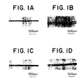
- Fig. 1B and Fig. 1D are photographs taken through a light microscope to show a state that a conventional ink composition is adhered to a glass substrate
- Fig. 1A and Fig. 1C are photographs taken through a light microscope to show a state that the ink composition of the invention is adhered to a glass substrate.
- FIG. 1B show a state that droplets are widely spaced as an experiment in order to clarify the effects of the ink composition of the present invention
- Fig. 1C and Fig. 1D show an example of drawing a line by continuously ejecting.
- the ink composition of the present invention has its all droplets arranged in good order with their shapes kept same, but the droplets of the conventional ink composition are deformed and not arranged in good order.
- the center of the line formed of the conventional ink composition has a portion lighter than its surroundings.
- the ink composition according to the invention can form a good pattern stably on the surface (a to-be-coloured layer) of the base material which is of the glass substrate and different from fiber of paper or the like.
- the surface of the basic material is a ceramics substrate or a film made of polyester resin or the like.
- the ink composition of the present invention contains a solvent, a pigment, and a dispersant which enhances the dispersion of the pigment into the solvent.
- the pigment contained in the droplets is kept uniformly dispersed within the droplets.
- the ink composition has physical properties such as a surface tension of 20.0 dyn/cm to 50.0 dyn/cm at 25°C and a viscosity of 1.5 cp to 20.0 cp at 25°C
- the ratio (S/V) of the surface area (S) of the interface, which is in contact with the gas phase, of the droplets to the volume (V) of the droplets can be kept minimum, in other words, the ratio (V/S) between the volume (V) of the droplets and the surface area (S) of the interface can be kept maximum, and the pigment contained in the droplets can be kept uniformly dispersed within the droplets.
- the ink composition of the invention contains a solvent, a pigment, and a dispersant which enhances the dispersion of the pigment into the solvent, and an additive can be added in addition to the solvent, pigment and dispersant in order to keep the ratio (S/V) of the surface area (S) of the interface, which is in contact with the gas phase, of the droplets to the volume (V) of the droplets minimum, in other words, keep maximum the ratio (V/S) between the volume (V) of the droplets and the surface area (S) of the interface in a process that the solvent is evaporating from the droplets after adhering the ink composition in the form of droplets onto the surface of the base material, and also to control the ink composition to have physical properties such as a surface tension of 20.0 dyn/cm to 50.0 dyn/cm at 25°C.
- the physical properties of the ink composition is adjusted to have a viscosity of 1.5 cp to 20.0 cp at 25°C. Therefore, the ink composition according to the invention can form a good pattern stably without causing light and dark portions or a partly different adhesive force of the pigment.
- the affinity of the solvent for the surface of the base material and its evaporation rate have a significant effect on steps A and B in Table 1.
- the solvent needs to have an affinity for the surface of the base material to obtain appropriate wettability and an appropriate evaporation rate as well.
- the solvent for the ink composition of the invention can be a mixture of water and various types of organic solvents to be used solely or as a mixture.
- organic solvents are at least one member selected from a group consisting of alkyl alcohols having 1 to 4 carbon atoms such as methyl alcohol, ethyl alcohol, n-propyl alcohol, isopropyl alcohol, n-butyl alcohol, sec-butyl alcohol, tert-butyl alcohol and isobutyl alcohol; amides such as dimethylformamide and dimethylacetamide; ketones or ketoalcohols such as acetone and diacetone alcohol; ethers such as tetrahydrofuran and dioxane; polyalkylene glycols such as polyethylene glycol and polypropylene glycol; alkylene glycols containing alkylene groups of two to six carbon atoms such as ethylene glycol, propylene glycol, butylene glycol, triethylene glycol, 1,2,
- a combination and a mixing ratio of the solvents are determined in a range that the properties of the ink composition are not deteriorated.
- the ink composition using water only as the solvent is defined as a water-based ink composition, and one using an organic solvent as the solvent is defined as a solvent-based ink composition.
- the pigment for the ink composition of the invention is desired to have an average particle diameter of 0.001 ⁇ m to 0.30 ⁇ m, preferably 0.05 ⁇ m to 0.15 ⁇ m, in view of the transparency of the pattern to be formed, and 0.5 ⁇ m to 50 ⁇ m, preferably 1 ⁇ m to 20 ⁇ m in view of securing a luminous efficacy for a phosphor.
- the average particle diameter is used to indicate as a diameter of the smallest sphere having the same surface area.
- the pigment for the ink composition of the invention can be various types depending on where it is used.
- examples include inorganic pigments such as carbon black, graphite black, iron black, Cu-Fe-Mn black, Co-Fe-Cr black, Cu-Cr-Mn black, titanium black, manganese black, cobalt black, ultramarine blue, cobalt blue, red oxide, cadmium red, cobalt green, sulfide phosphor, rare earth oxide phosphor, and rare earth oxysulfide phosphor; and organic pigments such as azo-based pigment, phthalocyanine-based pigment, indigo-based pigment, anthraquinone-based pigment, perylene-based pigment, perinone-based pigment, dioxazine-based pigment, quinacridone-based pigment, isoindorinone-based pigment, phthalone-based pigment, methine-azomethine-based pigment, and condensed polycyclic pigment. And, these pigments can be used
- the ink composition of the invention is to be applied for a color filter for the LCD, it is preferable to use copper phthalocyanine blue as a blue pigment, dioxazine violet as a purple pigment, anthraquinone red or perylene red as a red pigment, isoindorine yellow, benzidine yellow or isoindorinone yellow as a yellow pigment, phthalocyanine green as a green pigment, and carbon black, iron black, Cu-Fe-Mn black, Co-Fe-Cr black or Cu-Cr-Mn black as a black pigment.
- the ink composition of the invention is to be applied for a color filter for a color image receiving tube/PDP, it is preferable to use ultramarine blue or cobalt blue as a blue pigment, red oxide or cadmium red as a red pigment, cobalt green as a green pigment, and carbon black, iron black, graphite black, titanium black or cobalt black as a black pigment.
- the ink composition of the invention is to be applied for C-CRT/PDP phosphor picture elements, it is preferable to use Zn:Ag as a blue-luminous phosphor, Y 2 O 2 S:Eu or Y 2 O 3 :Eu as a red-luminous phosphor, ZnS:Cu, ZnS:Cu or Au as a green-luminous phosphor.
- the dispersant for the ink composition of the invention must be dispersed into the solvent so that it is adsorbed to the pigment to prevent the pigments from coagulating mutually, and it is also required to have a high affinity for a glass substrate.
- the dispersant which is adsorbed into the surface of the pigment contained in the ink composition serves to uniformly disperse the pigment into the ink composition, and also firmly adheres the pigment onto the surface of the base material. Therefore, the dispersant is related to step A in Table 1 and has a significant effect on step C.
- the dispersant for the ink composition of the invention is determined in view of combinations of the above-described ink composition types/pigments as required.
- the dispersant usable can be, for example, acrylic resin, polyvinyl acrylic pyrrolidone and polyvinyl alkyl pyrrolidone.
- the dispersant suitably usable is acrylic resin, polyvinyl alkyl pyrrolidone and the like when a combination of the ink composition type and the pigment is a water-based/inorganic pigment;
- the dispersant is polyvinyl butyral, acrylic resin, polyvinyl pyridine, polyamide resin, phenol resin, polyvinyl acrylic pyrrolidone, polyurethane resin and polyester resin when the combination is a solvent-based/organic pigment;
- the dispersant is polyvinyl butyral, acrylic resin and polyvinyl acrylic pyrrolidone when the combination is a solvent-based/inorganic pigment.
- the dispersant suitably usable includes polyvinyl butyral, acrylic resin, polyvinyl pyridine, polyamide resin, phenol resin or polyvinyl acrylic pyrrolidone when the pigment is an organic pigment.
- polyvinyl butyral, acrylic resin or polyvinyl acrylic pyrrolidone can be used suitably.
- the ink composition of the invention may contain an additive as a component for the ink composition in order to keep the ratio (S/V) of the surface area (S) of the interface, which is in contact with the gas phase, of the droplets to the volume (V) of the droplets minimum, in other words, keep maximum the ratio (V/S) between the volume (V) of the droplets and the surface area (S) of the interface in a process that the solvent is evaporating from the droplets after adhering the ink composition in the form of droplets onto the surface of the base material.
- the additive the physical properties of the ink composition can be controlled to have a surface tension of about 20.0 dyn/cm to about 50.0 dyn/cm at 25°C.
- the additive for the ink composition of the invention is suitably determined according to the above-described types of the ink composition.
- the additive preferably usable is at least one member selected from a group consisting of sodium dialkyl sulfosuccinate, fluorine-based surface active agent, and polyether modified silicone oil.
- the additive preferably usable is at least one member selected from a group consisting of silicone resin, acrylic resin, modified polysiloxane copolymer, polycarboxylic acid, polyester carboxylate, and unsaturated polycarboxylic acid.
- the ratio of the pigment in the ink composition it is 1 to 30 parts by weight, and preferably 3 to 15 parts by weight, to 100 parts by weight of the solvent to prevent a nozzle from being clogged by the ink composition and in view of an optical density (OD) of the pattern to be formed.
- the dispersant is 1 to 100 parts by weight and the additive is 1 to 30 parts by weight with respect to 100 parts by weight of the pigment. It is more preferable that the dispersant is 10 to 30 parts by weight and the additive is 3 to 10 parts by weight with respect to 100 parts by weight of the pigment.
- the dispersant When the dispersant is less than 1 part by weight to 100 parts by weight of the pigment, the dispersion of the pigment is degraded, causing it difficult to obtain the ink composition in which the pigment is uniformly dispersed. And, when the dispersant exceeds 100 parts by weight to 100 parts by weight of the pigment, the ink composition has a high viscosity, and the ink is not ejected uniformly from a nozzle in the ink-jet method, so that it is difficult to form a good pattern.
- the additive when the additive is less than 1 part by weight and exceeds 30 parts by weight with respect to 100 parts by weight of the pigment, in a process that the solvent is evaporating from the droplets after adhering the ink composition in the form of droplets onto the surface of the base material, it is difficult to control to minimize the ratio (S/V) of the surface area (S) of the interface, which is in contact with the gas phase, of the droplets to the volume (V) of the droplets, in other words, maximize the ratio (V/S) of the volume (V) of the droplets to the surface area (S) of the interface.
- the ink composition of the invention it is possible to add various types of components in a range not deteriorating the properties of the ink composition as required, such as a pH adjustor, a mildewproofing agent, a chelating agent or a reducing agent.
- a pattern forming method uses the above-described ink composition to form a pattern on the surface of a base material by the ink-jet method.
- the ink-jet method for ejecting the ink composition may be any method which can adhere the droplets of the ink composition onto the surface of a base material by effectively ejecting the ink composition from a nozzle.
- Suitably usable examples of the ink-jet method which ejects the ink composition include an electrostatic attraction method which applies an intense electrical field between a nozzle and an accelerating electrode provided several millimeters before the nozzle to change the ink composition to particles and extract successively from the nozzle and gives an information signal to deflecting electrodes while the extracted ink composition is flying between the deflecting electrodes to form a pattern; a method which applies a high pressure to ink by a small pump and mechanically vibrates a nozzle by a quartz oscillator or the like to forcedly eject the droplets of the ink composition, electrically charges the ejected droplets according to an information signal when they are ejected, and allows the charged droplets between deflecting electrode plates to deflect them according to a charged level, thereby forming a pattern; a method which gives an electrical signal to a piezoelectric element to cause a mechanical displacement to apply a pressure to the ink composition, and eject the droplets of the ink composition from
- the amount of the droplets of the ink composition to be adhered to the surface of a base material it is desired to control the amount of the droplets of the ink composition to be adhered to the surface of a base material. Specifically, if the amount of the droplets of the ink composition to be adhered to the surface of the base material is small, the amount of the pigment adhered to the surface of the base material is small, so that the optical density (OD) of the pattern formed is low, and it is hard to obtain prescribed optical properties. And, to remedy such a disadvantage, the amount of the pigment contained in the ink composition may be increased, thereby improving the optical density (OD) of the pattern. However, doing so makes it difficult to keep the properties of the ink composition and the nozzle tends to be clogged with the ink composition.
- the disadvantages cannot be remedied practically.
- the solvent contained in the ink composition is slow to evaporate in a moist atmosphere in the rainy season or the like and in a low-temperature environment in winter or the like, so that the adhesion of the pigment onto the surface of the base material is lowered, and it is hard to form a good pattern stably.
- the color filter according to the present invention has a base material and a colored layer which has a pigment adhered to the surface of the base material by the ink-jet method.
- this base material can be the above-described various types of base materials.
- Their examples include a glass substrate or a ceramics substrate; various types of film materials such as polyester resin, diacetate resin, triacetate resin, acrylic resin, polycarbonate resin, polyvinyl chloride resin, polyimide resin, cellophane or celluloid; and coated paper of which the surface is coated with organic polymer compounds such as polyamide or polyester.
- the pigment which forms the colored layer on the surface of the base material can be the above-described various types of pigments.
- the colored layer for the color filter according to the present invention is formed by adhering the above-described ink composition onto the surface of the base material by the ink-jet method and adhering the pigment contained in the ink composition onto the surface of the base material.
- the thickness of the colored layer of the color filter is determined according to a desired spectral characteristics, but generally desired to be about 0.01 to 5 ⁇ m.
- the colored layer itself for the color filter according to the invention has a sufficient durability, but to protect the colored layer from various environmental conditions, a resin of polyamide, polyimide, polyurethane, polycarbonate or silicone or an inorganic film of Si 3 N 4 , SiO 2 , SiO, Al 2 O 3 or Ta 2 O 3 can be formed as a protective layer on the surface of the colored layer by an application method such as spin coating or roll coating or a deposition method. When the provided protective layer is oriented, it can be applied to LCD easily.
- Fig. 1A is a photograph taken through a light microscope to show a state that the ink composition of the invention is adhered to a glass substrate.
- Fig. 1B is a photograph taken through a light microscope to show a state that a conventional ink composition is adhered to a glass substrate.
- Fig. 1C is a photograph taken through a light microscope to show a state that the ink composition of the invention is adhered to a glass substrate.
- Fig. 1D is a photograph taken through a light microscope to show a state that a conventional ink composition is adhered to a glass substrate.
- Fig. 2A is a schematic view showing a state that an ink composition is adhered to the surface of a glass substrate or ceramics substrate.
- Fig. 2B is a schematic view showing a state that a solvent is evaporating from a droplet of the ink composition.
- compositions A to C shown in Table 4 respective components were mixed and stirred in a stirring bath adjusted to 20°C, and passed through a filter having a pore diameter of 0.5 ⁇ m to prepare the ink compositions A to C.
- the pigment in the ink compositions A to C has an average particle diameter of about 0.1 ⁇ m.
- Table 5 shows viscosities and surface tensions of the ink compositions A to C at 25°C.
- Solmix AP-4 is sold by Nippon Kasei Chemical Co., Ltd.
- a glass substrate (with black matrix formed) for the display of LCD was mounted on a piezoelectric type ink-jet printer (MJ-800C; Seiko Epson Corp.; 720 dpi), and a color filter was produced using the ink compositions A to C.
- a piezoelectric type ink-jet printer MJ-800C; Seiko Epson Corp.; 720 dpi
- the obtained color filter had a good pattern with a black matrix (BM) width of about 40 ⁇ m and a pattern width of about 140 ⁇ m of each formed colored layer.
- BM black matrix
- the maximum difference among pattern widths of the formed colored layer was about 10 ⁇ m.
- Adhesion between the glass substrate and the each colored layer was good, and heat resistance, cold resistance and chemical resistance were equal to those of the colored layer of a conventional color filter formed by a dyeing method, a pigment dispersing method, an electrodeposition method or a printing method. Besides, optical properties of the colored layer were also same to those of the colored layer of the conventional color filter.
- the cost of forming the colored layer was about one fifth of the cost of forming the colored layer of the conventional color filter.
- compositions D to F shown in Table 4 respective components were mixed and stirred in a stirring bath adjusted to 20°C, and passed through a filter having a pore diameter of 0.5 ⁇ m to prepare the ink compositions D to F.
- the pigment in the ink compositions D to F has an average particle diameter of about 0.1 ⁇ m.
- Table 5 shows the viscosities and surface tensions of the ink compositions D to F at 25°C.
- Embodiment 1 The same glass substrate as used in Embodiment 1 was mounted on a piezoelectric type ink-jet printer (MJ-800C; Seiko Epson Corp.; 720 dpi), and a color filter was produced using the ink compositions D to F.
- a piezoelectric type ink-jet printer MJ-800C; Seiko Epson Corp.; 720 dpi
- the obtained color filter had a good pattern with a black matrix (BM) width of about 40 ⁇ m and a pattern width of about 140 ⁇ m of each formed colored layer.
- BM black matrix
- the maximum difference among pattern widths of the formed colored layer was about 10 ⁇ m.
- Adhesion between the glass substrate and the each colored layer was also good as in Embodiment 1, and heat resistance, cold resistance and chemical resistance were equal to those of the colored layer of a conventional color filter formed by a dyeing method, a pigment dispersing method, an electrodeposition method or a printing method. Besides, optical properties of the colored layer were also same to those of the colored layer of the conventional color filter.
- the cost of forming the colored layer was about one fifth of the cost of forming the colored layer of the conventional color filter.
- composition G shown in Table 4 respective components were mixed and stirred in a stirring bath adjusted to 20°C, and passed through a filter having a pore diameter of 0.5 ⁇ m to prepare the ink composition G.
- the pigment in the ink composition G has an average particle diameter of about 0.25 ⁇ m.
- Table 5 shows the viscosity and surface tension of the ink composition G at 25°C.
- Embodiment 1 The same glass substrate (without the BM) as used in Embodiment 1 was mounted on a piezoelectric type ink-jet printer (MJ-800C; Seiko Epson Corp.; 720 dpi), and a color filter was produced using the ink compositions A to C and G.
- a piezoelectric type ink-jet printer MJ-800C; Seiko Epson Corp.; 720 dpi
- the obtained color filter had a good pattern with a black matrix (BM) width of about 40 ⁇ m and a pattern width of about 140 ⁇ m of each formed colored layer.
- BM black matrix
- the maximum difference among pattern widths of the formed colored layer was about 10 ⁇ m.
- Adhesion between the glass substrate and the each colored layer was good, and heat resistance, cold resistance and chemical resistance were equal to those of the colored layer of a conventional color filter formed by a dyeing method, a pigment dispersing method, an electrodeposition method or a printing method. Besides, optical properties of the colored layer were also same to those of the colored layer of the conventional color filter.
- compositions H to J shown in Table 4 respective components were mixed and stirred in a stirring bath adjusted to 20°C, and passed through a filter having a pore diameter of 0.5 ⁇ m to prepare the ink compositions H to J.
- the pigments in the ink compositions H to J have an average particle diameter of about 0.023 ⁇ m, about 0.020 ⁇ m and about 0.021 ⁇ m.
- Table 5 shows viscosities and surface tensions of the ink compositions H to J at 25°C.
- a screen glass substrate (Nippon Electric Glass Co., Ltd.; with black matrix formed) for a 28-inch wide C-CRT was mounted on a piezoelectric type ink-jet printer (MJ-800C; Seiko Epson Corp.; 720 dpi), and a pattern of a colored layer of a color filter was produced using the ink compositions H to J.
- a color filter obtained had a pattern of each colored layer formed in black stripe holes having a pattern width of 150 ⁇ m.
- the maximum difference among pattern widths of the formed colored layer was about 10 ⁇ m.
- Adhesion between the glass substrate and the each colored layer was good, and heat resistance, cold resistance and chemical resistance of the each colored layer were equal to those of a conventional colored layer formed by a photolitho method. Besides, optical properties such as luminous brightness of the colored layer were also same to those of the colored layer of the conventional color filter.
- the cost of forming the colored layer including facilities investment was about 1/100 of the cost of forming the conventional colored layer. And, the amount of materials used for the colored layer was about 1/30.
- compositions K to M shown in Table 4 respective components were mixed and stirred in a stirring bath adjusted to 20°C, and passed through a filter having a pore diameter of 0.5 ⁇ m to prepare the ink compositions K to M.
- the pigments in the ink compositions K to M have an average particle diameter of about 0.023 ⁇ m, about 0.020 ⁇ m and about 0.021 ⁇ m.
- Table 5 shows viscosities and surface tensions of the ink compositions K to M at 25°C.
- the same screen glass substrate as used in Embodiment 4 was mounted on a piezoelectric type ink-jet printer (MJ-800C; Seiko Epson Corp.; 720 dpi), and a pattern of a colored layer for a color filter was produced using the ink compositions K to M.
- a piezoelectric type ink-jet printer MJ-800C; Seiko Epson Corp.; 720 dpi
- a color filter obtained had a pattern of each colored layer formed in black stripe holes having a pattern width of 150 ⁇ m.
- the maximum difference among pattern widths of the formed colored layer was about 10 ⁇ m.
- Adhesion between the glass substrate and the each colored layer was good, and heat resistance, cold resistance and chemical resistance of the each colored layer were equal to those of a conventional colored layer formed by a photolitho method. Besides, optical properties such as luminous brightness of the colored layer were also same to those of the colored layer of the conventional color filter.
- the cost of forming the colored layer including facilities investment was about 1/100 of the cost of forming the conventional colored layer. And, the amount of materials used for the colored layer was about 1/30.
- a screen glass substrate (Asahi Glass Co., Ltd.) for a 28-inch plasma display was mounted on a piezoelectric type ink-jet printer (MJ-800C; Seiko Epson Corp.; 720 dpi), and a pattern of a colored layer of a color filter was produced using the ink compositions H to J.
- a piezoelectric type ink-jet printer MJ-800C; Seiko Epson Corp.; 720 dpi
- a color filter obtained had a pattern of each colored layer formed in rectangular holes having a pattern width of 150 ⁇ m. On this color filter, the maximum difference among pattern widths of the formed colored layer was about 10 pm.
- Adhesion between the glass substrate and the each colored layer was good, and heat resistance, cold resistance and chemical resistance of the each colored layer were equal to those of a conventional colored layer formed by a photolitho method. Besides, optical properties such as luminous brightness of the colored layer were also same to those of the colored layer of the conventional color filter.
- the cost of forming the colored layer including facilities investment was about one fifth of the cost of forming the conventional colored layer. And, the amount of materials used for the colored layer was about 1/20.
- compositions N to P shown in Table 4 respective components were mixed and stirred in a stirring bath adjusted to 20°C, and passed through a filter having a pore diameter of 0.5 ⁇ m to prepare the ink compositions N to P.
- the pigments in the ink compositions N to P have an average particle diameter of about 0.023 ⁇ m, about 0.020 ⁇ m and about 0.021 ⁇ m.
- Table 5 shows viscosities and surface tensions of the ink compositions N to P at 25°C.
- a screen glass substrate (Asahi Glass Co., Ltd.) for a 28-inch plasma display was mounted on a piezoelectric type ink-jet printer (MJ-800C; Seiko Epson Corp.; 720 dpi), and a pattern of a colored layer of a color filter was produced using the ink compositions N to P.
- a piezoelectric type ink-jet printer MJ-800C; Seiko Epson Corp.; 720 dpi
- a color filter obtained had a pattern of each colored layer formed in rectangular holes having a pattern width of 150 ⁇ m.
- the maximum difference among pattern widths of the formed colored layer was about 10 ⁇ m.
- Adhesion between the glass substrate and the each colored layer was good, and heat resistance, cold resistance and chemical resistance of the each colored layer were equal to those of a conventional colored layer formed by a photolitho method. Besides, optical properties such as luminous brightness of the colored layer were also same to those of the colored layer of the conventional color filter.
- the cost of forming the colored layer including facilities investment was about one fifth of the cost of forming the conventional colored layer. And, the amount of materials used for the colored layer was about 1/20.
- compositions Q to S shown in Table 4 respective components were mixed and stirred in a stirring bath adjusted to 20°C, and passed through a filter having a pore diameter of 0.5 ⁇ m to prepare the ink compositions Q to S.
- the pigments in the ink compositions Q to S have an average particle diameter of about 0.010 ⁇ m.
- Table 5 shows viscosities and surface tensions of the ink compositions Q to S at 25°C.
- a wafer with a CCD (Charge Coupled Device) formed was mounted on a piezoelectric type ink-jet printer (MJ-800C; Seiko Epson Corp.; 720 dpi). And, to provide a pattern of each colored layer for a color filter in correspondence with each photo cell of the CCD, a pattern of a colored layer for the color filter was produced using the ink compositions Q to S.
- CCD Charge Coupled Device
- a color filter obtained had a pattern of each colored layer having a pattern width of 150 ⁇ m.
- the maximum difference among pattern widths of the formed colored layer was about 10 ⁇ m.
- Adhesion between the wafer and the each colored layer was good, and heat resistance, cold resistance and chemical resistance of the each colored layer were equal to those of a conventional colored layer formed by a photolitho method. Besides, optical properties of the colored layer were also same to those of the colored layer of the conventional color filter.
- the cost of forming the colored layer including facilities investment was about 1/100 of the cost of forming the conventional colored layer. And, the amount of materials used for the colored layer was about 1/30.
- composition T shown in Table 4 respective components were mixed and stirred in a stirring bath adjusted to 20°C, and passed through a filter having a pore diameter of 0.5 ⁇ m to prepare the ink composition T.
- the pigment in the ink composition T has an average particle diameter of about 0.025 ⁇ m.
- Table 5 shows the viscosity, surface tension and density of the ink composition T at 25°C.
- a polyester-based OHP film was mounted on a piezoelectric type ink-jet printer (MJ-800C; Seiko Epson Corp.; 720 dpi). And, a character pattern was formed on the OHP by using the ink composition T.
- a piezoelectric type ink-jet printer MJ-800C; Seiko Epson Corp.; 720 dpi.
- the OHP film obtained has the character pattern having a pattern width of 250 ⁇ m.
- the maximum difference among the formed character pattern widths was about 15 ⁇ m.
- Adhesion between the OHP film and the colored layer forming the character patterns was good, and heat resistance, cold resistance and chemical resistance of the colored layer were equal to those of a conventional colored layer formed on an OHP film. Besides, optical properties of the colored layer such as OD were also same to those of the conventional colored layer.
- the pigment is uniformly dispersed in the droplets adhered onto the surface of glass, ceramics or polyester resin of a base material. Therefore, a fine pattern can be formed on the surface of glass, ceramics or polyester resin by the ink-jet method without forming a to-be-colored layer.
- a pattern is formed by the ink-jet method using the ink composition containing the pigment which is uniformly dispersed in the droplets adhered onto the surface of glass, ceramics or polyester resin of a base material, so that a fine pattern having high reliability can be formed indirectly onto the surface of glass, ceramics or polyester resin of the base material. Therefore, the number of processes and facilities investment can be decreased and the pattern can be formed on the base material economically.
- the color filter of the present invention has the colored layer formed of the pigment adhered onto the surface of a base material by the ink-jet method, practical reliability in optical resistance and water resistance and cost efficiency can be improved.
Abstract
Description
- The present invention relates to an ink composition, a pattern forming method and a color filter, and particularly to an ink composition used to form a pattern by an ink-jet method, a pattern forming method which uses the above ink composition, and a color filter which is produced by the pattern forming method using the above ink composition.
- The pattern forming method according to the ink-jet method sprays droplets of an ink composition onto a base material by various types of ink composition ejecting methods such as an electrostatic attraction method, a method which employs a piezoelectric element to mechanically vibrate or bias ink, or a method of heating to foam ink and using a pressure by the foamed ink to form a pattern on the surface of the base material. And, the pattern forming method according to the ink-jet method has advantages that a pattern can be formed quickly without involving production of large noise, and a multi-colored pattern can be formed easily. Therefore, it is attracting attention in many fields.
- Meanwhile, color filters which are used for display units such as a CRT, a liquid crystal display and a plasma display, or a solid state image pickup device and the like have been produced by various types of methods such as a pigment dispersion method, a dye dispersion method, and a dyeing method.
- For example, Japanese Patent Laid-Open Publication No. Hei 7-179711 describes a method of producing a fluorescent film with a filter by forming a patterned photo absorption layer on the inner face of a face plate, applying a pigment dispersed solution and a phosphor slurry, and exposing through a mask and developing. And, Japanese Patent Laid-Open Publication No. Sho 59-75205 describes a method of producing a color filter by forming a colored layer on a substrate by the ink-jet method.
- However, the method of producing a fluorescent film with a filter described in Japanese Patent Laid-Open Publication No. Hei 7-179711 has a disadvantage that the production cost is high because it involves many steps to produce the fluorescent film, and the application of a pigment dispersed solution and a phosphor slurry and the exposure through a mask and development are required for each color. And, the method of producing a color filter described in Japanese Patent Laid-Open Publication No. Sho 59-75205 which forms a colored layer on a substrate by the ink-jet method has disadvantages that a dispersion preventive pattern or a wettability improver must be formed on a glass substrate in advance, increasing facilities investment and the number of processes, also increasing the production cost, and lowering a production yield.
- The present invention has been completed in view of the above circumstances, and aims to provide an ink composition which can form a fine pattern on the surface of glass, ceramics or polyester resins by the ink-jet method without requiring to form a wettability improver.
- The present invention also aims to provide a pattern forming method which can easily form a fine pattern efficiently on the surface of a glass substrate or the like, and does not involve many processes or facilities investment, so that the formed pattern excels in reliability and economy.
- Besides, the present invention aims to provide a color filter having a pattern which excels in optical resistance and water resistance and has high reliability in practical use, and which also excels in economy.
- An ink composition according to the present invention is controlled to keep maximum the ratio (V/S) of the volume (V) of a system which consists of a solvent, a pigment dispersed into the solvent and a dispersant which is dispersed into the solvent to enhance an affinity between the solvent and the pigment; and the surface area (S) of an interface of the system produced on a boundary between the system and a gas phase.
- And, an ink composition according to the present invention may have a system which includes or consists of a solvent, a pigment dispersed into the solvent and a dispersant which is dispersed into the solvent to enhance an affinity between the solvent and the pigment, and the system has (1) a surface tension of 20.0 dyn/cm to 50.0 dyn/cm at 25°C, and (2) a viscosity of 1.5 cp to 20.0 cp at 25°C.
- Besides, an ink composition according to the present invention may contain a solvent, a pigment dispersed into the solvent, a dispersant which is dispersed into the solvent to enhance an affinity between the solvent and the pigment, and an additive which is dispersed into the solvent to control free energy of an interface.
- A pattern forming method according to the invention has a step of ejecting from a nozzle by an ink-jet method droplets of an ink composition of which the ratio (V/S) between the volume (V) of a system which consists of a solvent, a pigment dispersed into the solvent and a dispersant which is dispersed into the solvent to enhance the affinity between the solvent and the pigment; and the surface area (S) of the interface of the system produced on at the boundary between the system and a gas phase is controlled to be kept at a maximum, a step of adhering the droplets onto the surface of a base material, and a step of adhering the pigment contained in the droplets onto the base material.
- And, a pattern forming method according to the invention has a step of ejecting from a nozzle by an ink-jet method droplets of an ink composition having a system which consists of a solvent, a pigment dispersed into the solvent and a dispersant which is dispersed into the solvent to enhance an affinity between the solvent and the pigment, and which has (1) a surface tension of 20.0 dyn/cm to 50.0 dyn/cm at 25°C and (2) a viscosity of 1.5 cp to 20.0 cp at 25°C, a step of adhering the droplets onto the surface of a base material, and a step of adhering the pigment contained in the droplets onto the base material.
- Furthermore, a pattern forming method according to the invention has a step of ejecting from a nozzle by an ink-jet method droplets of an ink composition containing a solvent, a pigment dispersed into the solvent, a dispersant which is dispersed into the solvent to enhance an affinity between the solvent and the pigment, and an additive which is dispersed into the solvent to control free energy of an interface, a step of adhering the droplets onto the surface of a base material, and a step of adhering the pigment contained in the droplets onto the base material.
- A color filter according to the invention has a base material and a colored layer which is formed of a pigment adhered to the surface of the base material by an ink-jet method.
- Generally, to form a pattern of picture elements for a color filter by an ink-jet method, when a base material has a surface (to-be-colored layer) of glass, ceramics or a film material made of polyester resin or the like which is different from fiber of paper or the like, a conventional ink composition is not adequately adhered to the surface of such a base material, and the ink composition is repelled or spreads on the surface of the base material. And, since the adhesion of a coloring matter to the surface of the base material is weak, it is easily separated from the surface of the base material, and the formed pattern is broken in a short period. The base material used herein generally means those having a to-be-colored layer surface, onto which the coloring matter of the ink composition is adhered, with a structure of glass, ceramics or a film made of polyester resin or the like which is different from fiber of paper or the like. Therefore, the base materials belonging to such a category can be a glass substrate or a ceramics substrate; various types of film materials such as polyester resin, diacetate resin, triacetate resin, acrylic resin, polycarbonate resin, polyvinyl chloride resin, polyimide resin, cellophane or celluloid; and coated paper of which the surface is coated with organic polymer compounds such as polyamide or polyester.
- Fig. 2A and Fig. 2B are schematic views showing a process that an ink composition is adhered to the surface of a base material such as a glass substrate or ceramics substrate and a solvent evaporates from a droplet of the ink composition.
- Specifically, when an
ink composition 203 is adhered to asurface 202 of abase material 201, the surface area (S) of aninterface 204, which is in contact with a gas phase, of theink composition 203 is kept to have the minimum ratio (S/V) to the volume (V) of theink composition 203, in other words, the ratio (V/S) between the volume (V) of theink composition 203 and the surface area (S) of theinterface 204 is controlled to be kept at a maximum as shown in Fig. 2A. But, as the solvent evaporates from the ink composition, the minimum ratio between the surface area of theinterface 204, which is in contact with the gas phase, of theink composition 203 and the volume of theink composition 203 cannot be kept, and the ratio of the surface area of theinterface 204, which is in contact with the gas phase, of theink composition 203 to the volume of the ink composition increases as shown in Fig. 2B. More specifically, the middle of theink composition 203 adhered to thesurface 202 of thebase material 201 sinks toward thebase material 201, and the ratio of the surface area of theinterface 204, which is in contact with the gas phase, of theink composition 203 to the volume of the ink composition increases as shown in Fig. 2B. And, apigment 205 contained in theink composition 203 is concentrated toward portions (circumference) 206a and 206b of the interface of theink composition 203, and the uniform dispersion of thepigment 205 within theink composition 203 is lost. Therefore, a pattern formed by the adhesion of thepigment 205 to thesurface 202 of thebase material 201 has light and dark portions. And, it is hard to stably form a good pattern because the adhesive force to the surface of the substrate is partly different. - The inventors have repeated various experiments, and finally found an ink composition which forms a good pattern without involving the above-described disadvantages by selecting types and particle diameters of a pigment as the coloring matter, a dispersant, and a solvent. In the experiments, respective steps shown in Table 1 were taken into account.
Table 1 Conventional ink composition Ink composition to provide good pattern A. Surface of base material Droplets deform Droplet shape is substantially constant B. Solvent evaporates Further deforms Droplet shape is not deformed heavily C. Most solvent has evaporated Weak adhesion of pigment Pigment adheres firmly to base material - It is apparent from Table 1 that in order to form a good pattern, when the solvent evaporates from the ink composition adhered to the surface of the base material, the shape of droplets of the ink composition on the surface of the base material must be kept to have the base material wet with the droplets. And, the pigment contained in the ink composition is required to have an affinity for the surface of the base material and a high adhesive force.
- To meet such conditions, various experiments have been made to find materials for the ink composition, and the results obtained are shown in Table 2 and Table 3. Symbols o, Δ and x in Table 2 and Table 3 indicate a good level, a practical level and an unpractical level, respectively.
Table 2 Materials for ink composition State of ink composition adhered to base material No. Solvent Dispersant Repellency Spreading Adhesive force 1 Water Nonionic surface active agent Δ ∼ ○ X X 2 Water Anionic surface active agent Δ ∼ ○ X X 3 Water Cationic surface active agent Δ ∼ ○ X X 
- Table 2 shows the results obtained when conventional ink compositions were adhered to a glass substrate, and Table 3 shows the results also obtained when the ink composition of the present invention was adhered to a glass substrate. In order that the invention may be illustrated and readily carried into effect, embodiments thereof will now be described by way of non-limiting examples only, with reference to the accompanying photographs and drawings. Fig. 1B and Fig. 1D are photographs taken through a light microscope to show a state that a conventional ink composition is adhered to a glass substrate, and Fig. 1A and Fig. 1C are photographs taken through a light microscope to show a state that the ink composition of the invention is adhered to a glass substrate. Fig. 1A and Fig. 1B show a state that droplets are widely spaced as an experiment in order to clarify the effects of the ink composition of the present invention, and Fig. 1C and Fig. 1D show an example of drawing a line by continuously ejecting. It is apparent from Fig. 1A and Fig. 1B that the ink composition of the present invention has its all droplets arranged in good order with their shapes kept same, but the droplets of the conventional ink composition are deformed and not arranged in good order. And, it is apparent from Fig. 1C and Fig. 1D that the center of the line formed of the conventional ink composition has a portion lighter than its surroundings. In other words, it is apparent from Fig. 1A to Fig. 1D that the ink composition according to the invention can form a good pattern stably on the surface (a to-be-coloured layer) of the base material which is of the glass substrate and different from fiber of paper or the like. The same result can also be obtained when the surface of the basic material is a ceramics substrate or a film made of polyester resin or the like.
- Now, the ink composition of the present invention will be described in detail.
- The ink composition of the present invention contains a solvent, a pigment, and a dispersant which enhances the dispersion of the pigment into the solvent. By appropriately controlling the types, amounts and component ratios of the solvent, pigment and dispersant, after adhering droplets of the ink composition onto the surface of a base material, the ratio (S/V) of the surface area (S) of the interface, which is in contact with the gas phase, of the droplets to the volume (V) of the droplets is kept minimum, in other words, the ratio (V/S) between the volume (V) of the droplets and the surface area (S) of the interface is kept maximum while the solvent is evaporating from the droplets. Therefore, while the solvent is evaporating from the droplets, the pigment contained in the droplets is kept uniformly dispersed within the droplets. And, when the ink composition has physical properties such as a surface tension of 20.0 dyn/cm to 50.0 dyn/cm at 25°C and a viscosity of 1.5 cp to 20.0 cp at 25°C, in a process that the solvent is evaporating from the droplets after adhering onto the surface of the base material, the ratio (S/V) of the surface area (S) of the interface, which is in contact with the gas phase, of the droplets to the volume (V) of the droplets can be kept minimum, in other words, the ratio (V/S) between the volume (V) of the droplets and the surface area (S) of the interface can be kept maximum, and the pigment contained in the droplets can be kept uniformly dispersed within the droplets. Besides, the ink composition of the invention contains a solvent, a pigment, and a dispersant which enhances the dispersion of the pigment into the solvent, and an additive can be added in addition to the solvent, pigment and dispersant in order to keep the ratio (S/V) of the surface area (S) of the interface, which is in contact with the gas phase, of the droplets to the volume (V) of the droplets minimum, in other words, keep maximum the ratio (V/S) between the volume (V) of the droplets and the surface area (S) of the interface in a process that the solvent is evaporating from the droplets after adhering the ink composition in the form of droplets onto the surface of the base material, and also to control the ink composition to have physical properties such as a surface tension of 20.0 dyn/cm to 50.0 dyn/cm at 25°C. At this time, the physical properties of the ink composition is adjusted to have a viscosity of 1.5 cp to 20.0 cp at 25°C. Therefore, the ink composition according to the invention can form a good pattern stably without causing light and dark portions or a partly different adhesive force of the pigment.
- In the ink composition according to the invention, the affinity of the solvent for the surface of the base material and its evaporation rate have a significant effect on steps A and B in Table 1. In other words, to accurately position the ink composition on the surface of the base material, the solvent needs to have an affinity for the surface of the base material to obtain appropriate wettability and an appropriate evaporation rate as well.
- To meet such conditions, the solvent for the ink composition of the invention can be a mixture of water and various types of organic solvents to be used solely or as a mixture. Preferably usable organic solvents are at least one member selected from a group consisting of alkyl alcohols having 1 to 4 carbon atoms such as methyl alcohol, ethyl alcohol, n-propyl alcohol, isopropyl alcohol, n-butyl alcohol, sec-butyl alcohol, tert-butyl alcohol and isobutyl alcohol; amides such as dimethylformamide and dimethylacetamide; ketones or ketoalcohols such as acetone and diacetone alcohol; ethers such as tetrahydrofuran and dioxane; polyalkylene glycols such as polyethylene glycol and polypropylene glycol; alkylene glycols containing alkylene groups of two to six carbon atoms such as ethylene glycol, propylene glycol, butylene glycol, triethylene glycol, 1,2,6-hexanetriol, thiodiglycol, hexylene glycol, and diethylene glycol; lower alkyl ethers of polyhydric alcohol such as ethylene glycol methyl ether, ethylene glycol ethyl ether, triethylene glycol monomethyl ether, and triethylene glycol monoethylene ether; and esters such as ethyl acetate and butyl acetate. To use a plurality of solvents in a mixed form, a combination and a mixing ratio of the solvents are determined in a range that the properties of the ink composition are not deteriorated. The ink composition using water only as the solvent is defined as a water-based ink composition, and one using an organic solvent as the solvent is defined as a solvent-based ink composition.
- And, to stably form a good pattern without causing light and dark portions or a partly different adhesive force of the pigment, the pigment for the ink composition of the invention is desired to have an average particle diameter of 0.001 µm to 0.30 µm, preferably 0.05 µm to 0.15 µm, in view of the transparency of the pattern to be formed, and 0.5 µm to 50 µm, preferably 1 µm to 20 µm in view of securing a luminous efficacy for a phosphor. The average particle diameter is used to indicate as a diameter of the smallest sphere having the same surface area.
- The pigment for the ink composition of the invention can be various types depending on where it is used. And examples include inorganic pigments such as carbon black, graphite black, iron black, Cu-Fe-Mn black, Co-Fe-Cr black, Cu-Cr-Mn black, titanium black, manganese black, cobalt black, ultramarine blue, cobalt blue, red oxide, cadmium red, cobalt green, sulfide phosphor, rare earth oxide phosphor, and rare earth oxysulfide phosphor; and organic pigments such as azo-based pigment, phthalocyanine-based pigment, indigo-based pigment, anthraquinone-based pigment, perylene-based pigment, perinone-based pigment, dioxazine-based pigment, quinacridone-based pigment, isoindorinone-based pigment, phthalone-based pigment, methine-azomethine-based pigment, and condensed polycyclic pigment. And, these pigments can be used solely or in a mixed form. To disperse an organic pigment into the solvent-based ink composition, a combination of the organic solvent and the organic pigment shall be selected so that the organic pigment does not dissolve into the organic solvent.
- When the ink composition of the invention is to be applied for a color filter for the LCD, it is preferable to use copper phthalocyanine blue as a blue pigment, dioxazine violet as a purple pigment, anthraquinone red or perylene red as a red pigment, isoindorine yellow, benzidine yellow or isoindorinone yellow as a yellow pigment, phthalocyanine green as a green pigment, and carbon black, iron black, Cu-Fe-Mn black, Co-Fe-Cr black or Cu-Cr-Mn black as a black pigment. And, when the ink composition of the invention is to be applied for a color filter for a color image receiving tube/PDP, it is preferable to use ultramarine blue or cobalt blue as a blue pigment, red oxide or cadmium red as a red pigment, cobalt green as a green pigment, and carbon black, iron black, graphite black, titanium black or cobalt black as a black pigment. Furthermore, when the ink composition of the invention is to be applied for C-CRT/PDP phosphor picture elements, it is preferable to use Zn:Ag as a blue-luminous phosphor, Y2O2S:Eu or Y2O3:Eu as a red-luminous phosphor, ZnS:Cu, ZnS:Cu or Au as a green-luminous phosphor.
- Besides, the dispersant for the ink composition of the invention must be dispersed into the solvent so that it is adsorbed to the pigment to prevent the pigments from coagulating mutually, and it is also required to have a high affinity for a glass substrate. The dispersant which is adsorbed into the surface of the pigment contained in the ink composition serves to uniformly disperse the pigment into the ink composition, and also firmly adheres the pigment onto the surface of the base material. Therefore, the dispersant is related to step A in Table 1 and has a significant effect on step C.
- To meet the above-described conditions, the dispersant for the ink composition of the invention is determined in view of combinations of the above-described ink composition types/pigments as required. Specifically, for a combination of the water-based ink composition/organic pigment, the dispersant usable can be, for example, acrylic resin, polyvinyl acrylic pyrrolidone and polyvinyl alkyl pyrrolidone. Similarly, the dispersant suitably usable is acrylic resin, polyvinyl alkyl pyrrolidone and the like when a combination of the ink composition type and the pigment is a water-based/inorganic pigment; the dispersant is polyvinyl butyral, acrylic resin, polyvinyl pyridine, polyamide resin, phenol resin, polyvinyl acrylic pyrrolidone, polyurethane resin and polyester resin when the combination is a solvent-based/organic pigment; and the dispersant is polyvinyl butyral, acrylic resin and polyvinyl acrylic pyrrolidone when the combination is a solvent-based/inorganic pigment. When an organic solvent is to be used as the solvent in the ink composition of the present invention, it is more preferable to use alcohols. When alcohols are used as the organic solvent, the dispersant suitably usable includes polyvinyl butyral, acrylic resin, polyvinyl pyridine, polyamide resin, phenol resin or polyvinyl acrylic pyrrolidone when the pigment is an organic pigment. On the other hand, when an inorganic pigment is to be used, polyvinyl butyral, acrylic resin or polyvinyl acrylic pyrrolidone can be used suitably.
- Furthermore, the ink composition of the invention may contain an additive as a component for the ink composition in order to keep the ratio (S/V) of the surface area (S) of the interface, which is in contact with the gas phase, of the droplets to the volume (V) of the droplets minimum, in other words, keep maximum the ratio (V/S) between the volume (V) of the droplets and the surface area (S) of the interface in a process that the solvent is evaporating from the droplets after adhering the ink composition in the form of droplets onto the surface of the base material. When the additive is used, the physical properties of the ink composition can be controlled to have a surface tension of about 20.0 dyn/cm to about 50.0 dyn/cm at 25°C.
- The additive for the ink composition of the invention is suitably determined according to the above-described types of the ink composition. Specifically, when the ink composition is water-based, the additive preferably usable is at least one member selected from a group consisting of sodium dialkyl sulfosuccinate, fluorine-based surface active agent, and polyether modified silicone oil. And, when the ink composition is solvent-based, the additive preferably usable is at least one member selected from a group consisting of silicone resin, acrylic resin, modified polysiloxane copolymer, polycarboxylic acid, polyester carboxylate, and unsaturated polycarboxylic acid.
- And, as to the ratio of the pigment in the ink composition, it is 1 to 30 parts by weight, and preferably 3 to 15 parts by weight, to 100 parts by weight of the solvent to prevent a nozzle from being clogged by the ink composition and in view of an optical density (OD) of the pattern to be formed.
- On the other hand, it is preferable that the dispersant is 1 to 100 parts by weight and the additive is 1 to 30 parts by weight with respect to 100 parts by weight of the pigment. It is more preferable that the dispersant is 10 to 30 parts by weight and the additive is 3 to 10 parts by weight with respect to 100 parts by weight of the pigment.
- When the dispersant is less than 1 part by weight to 100 parts by weight of the pigment, the dispersion of the pigment is degraded, causing it difficult to obtain the ink composition in which the pigment is uniformly dispersed. And, when the dispersant exceeds 100 parts by weight to 100 parts by weight of the pigment, the ink composition has a high viscosity, and the ink is not ejected uniformly from a nozzle in the ink-jet method, so that it is difficult to form a good pattern.
- And, when the additive is less than 1 part by weight and exceeds 30 parts by weight with respect to 100 parts by weight of the pigment, in a process that the solvent is evaporating from the droplets after adhering the ink composition in the form of droplets onto the surface of the base material, it is difficult to control to minimize the ratio (S/V) of the surface area (S) of the interface, which is in contact with the gas phase, of the droplets to the volume (V) of the droplets, in other words, maximize the ratio (V/S) of the volume (V) of the droplets to the surface area (S) of the interface.
- In addition, to the ink composition of the invention, it is possible to add various types of components in a range not deteriorating the properties of the ink composition as required, such as a pH adjustor, a mildewproofing agent, a chelating agent or a reducing agent.
- A pattern forming method according to the present invention uses the above-described ink composition to form a pattern on the surface of a base material by the ink-jet method. In the pattern forming method according to the present invention, the ink-jet method for ejecting the ink composition may be any method which can adhere the droplets of the ink composition onto the surface of a base material by effectively ejecting the ink composition from a nozzle. Suitably usable examples of the ink-jet method which ejects the ink composition include an electrostatic attraction method which applies an intense electrical field between a nozzle and an accelerating electrode provided several millimeters before the nozzle to change the ink composition to particles and extract successively from the nozzle and gives an information signal to deflecting electrodes while the extracted ink composition is flying between the deflecting electrodes to form a pattern; a method which applies a high pressure to ink by a small pump and mechanically vibrates a nozzle by a quartz oscillator or the like to forcedly eject the droplets of the ink composition, electrically charges the ejected droplets according to an information signal when they are ejected, and allows the charged droplets between deflecting electrode plates to deflect them according to a charged level, thereby forming a pattern; a method which gives an electrical signal to a piezoelectric element to cause a mechanical displacement to apply a pressure to the ink composition, and eject the droplets of the ink composition from a nozzle; and a method which applies thermal energy to the ink composition to cause a sharp volume change in the ink composition to eject the droplets of the ink composition from a nozzle.
- Furthermore, in the case of forming a pattern of picture elements for a color filter, it is desired to control the amount of the droplets of the ink composition to be adhered to the surface of a base material. Specifically, if the amount of the droplets of the ink composition to be adhered to the surface of the base material is small, the amount of the pigment adhered to the surface of the base material is small, so that the optical density (OD) of the pattern formed is low, and it is hard to obtain prescribed optical properties. And, to remedy such a disadvantage, the amount of the pigment contained in the ink composition may be increased, thereby improving the optical density (OD) of the pattern. However, doing so makes it difficult to keep the properties of the ink composition and the nozzle tends to be clogged with the ink composition. Thus, the disadvantages cannot be remedied practically. On the other hand, if the amount of the droplets of the ink composition to be adhered to the surface of a base material is large, even if the amount of the pigment contained in the ink composition is decreased, the solvent contained in the ink composition is slow to evaporate in a moist atmosphere in the rainy season or the like and in a low-temperature environment in winter or the like, so that the adhesion of the pigment onto the surface of the base material is lowered, and it is hard to form a good pattern stably.
- When a water-based ink composition is used in the pattern forming method according to the invention, it is desired to keep the surface of the base material, to which the droplets of the ink composition are adhered, at 20°C to 120°C in view of controlling the evaporation rate of the solvent water.
- The color filter according to the present invention has a base material and a colored layer which has a pigment adhered to the surface of the base material by the ink-jet method. And, this base material can be the above-described various types of base materials. Their examples include a glass substrate or a ceramics substrate; various types of film materials such as polyester resin, diacetate resin, triacetate resin, acrylic resin, polycarbonate resin, polyvinyl chloride resin, polyimide resin, cellophane or celluloid; and coated paper of which the surface is coated with organic polymer compounds such as polyamide or polyester. And, they can be applied for a display unit such as LCD, CRT or PDP, a wafer having a solid state image pickup device such as the light receiving face of a camera tube, CCD, BBD, CID or BASIS, and a contact image sensor using a thin film semiconductor. And, the pigment which forms the colored layer on the surface of the base material can be the above-described various types of pigments.
- The colored layer for the color filter according to the present invention is formed by adhering the above-described ink composition onto the surface of the base material by the ink-jet method and adhering the pigment contained in the ink composition onto the surface of the base material. The thickness of the colored layer of the color filter is determined according to a desired spectral characteristics, but generally desired to be about 0.01 to 5 µm.
- The colored layer itself for the color filter according to the invention has a sufficient durability, but to protect the colored layer from various environmental conditions, a resin of polyamide, polyimide, polyurethane, polycarbonate or silicone or an inorganic film of Si3N4, SiO2, SiO, Al2O3 or Ta2O3 can be formed as a protective layer on the surface of the colored layer by an application method such as spin coating or roll coating or a deposition method. When the provided protective layer is oriented, it can be applied to LCD easily.
- Fig. 1A is a photograph taken through a light microscope to show a state that the ink composition of the invention is adhered to a glass substrate.
- Fig. 1B is a photograph taken through a light microscope to show a state that a conventional ink composition is adhered to a glass substrate.
- Fig. 1C is a photograph taken through a light microscope to show a state that the ink composition of the invention is adhered to a glass substrate.
- Fig. 1D is a photograph taken through a light microscope to show a state that a conventional ink composition is adhered to a glass substrate.
- Fig. 2A is a schematic view showing a state that an ink composition is adhered to the surface of a glass substrate or ceramics substrate.
- Fig. 2B is a schematic view showing a state that a solvent is evaporating from a droplet of the ink composition.
- Embodiments of the invention will be described in detail with reference to the accompanying drawings. In the following embodiments, the symbol "%" indicates a percent by weight.
- In accordance with compositions A to C shown in Table 4, respective components were mixed and stirred in a stirring bath adjusted to 20°C, and passed through a filter having a pore diameter of 0.5 µm to prepare the ink compositions A to C. The pigment in the ink compositions A to C has an average particle diameter of about 0.1 µm. And, Table 5 shows viscosities and surface tensions of the ink compositions A to C at 25°C. Solmix AP-4 is sold by Nippon Kasei Chemical Co., Ltd.
- A glass substrate (with black matrix formed) for the display of LCD was mounted on a piezoelectric type ink-jet printer (MJ-800C; Seiko Epson Corp.; 720 dpi), and a color filter was produced using the ink compositions A to C.
- And, the obtained color filter had a good pattern with a black matrix (BM) width of about 40 µm and a pattern width of about 140 µm of each formed colored layer. On this color filter, the maximum difference among pattern widths of the formed colored layer was about 10 µm.
- Adhesion between the glass substrate and the each colored layer was good, and heat resistance, cold resistance and chemical resistance were equal to those of the colored layer of a conventional color filter formed by a dyeing method, a pigment dispersing method, an electrodeposition method or a printing method. Besides, optical properties of the colored layer were also same to those of the colored layer of the conventional color filter.
- The cost of forming the colored layer was about one fifth of the cost of forming the colored layer of the conventional color filter.
- In accordance with compositions D to F shown in Table 4, respective components were mixed and stirred in a stirring bath adjusted to 20°C, and passed through a filter having a pore diameter of 0.5 µm to prepare the ink compositions D to F. The pigment in the ink compositions D to F has an average particle diameter of about 0.1 µm. And, Table 5 shows the viscosities and surface tensions of the ink compositions D to F at 25°C.
- The same glass substrate as used in Embodiment 1 was mounted on a piezoelectric type ink-jet printer (MJ-800C; Seiko Epson Corp.; 720 dpi), and a color filter was produced using the ink compositions D to F.
- And, the obtained color filter had a good pattern with a black matrix (BM) width of about 40 µm and a pattern width of about 140 µm of each formed colored layer. On this color filter, the maximum difference among pattern widths of the formed colored layer was about 10 µm.
- Adhesion between the glass substrate and the each colored layer was also good as in Embodiment 1, and heat resistance, cold resistance and chemical resistance were equal to those of the colored layer of a conventional color filter formed by a dyeing method, a pigment dispersing method, an electrodeposition method or a printing method. Besides, optical properties of the colored layer were also same to those of the colored layer of the conventional color filter.
- The cost of forming the colored layer was about one fifth of the cost of forming the colored layer of the conventional color filter.
- In accordance with composition G shown in Table 4, respective components were mixed and stirred in a stirring bath adjusted to 20°C, and passed through a filter having a pore diameter of 0.5 µm to prepare the ink composition G. The pigment in the ink composition G has an average particle diameter of about 0.25 µm. And, Table 5 shows the viscosity and surface tension of the ink composition G at 25°C.
- The same glass substrate (without the BM) as used in Embodiment 1 was mounted on a piezoelectric type ink-jet printer (MJ-800C; Seiko Epson Corp.; 720 dpi), and a color filter was produced using the ink compositions A to C and G.
- And, the obtained color filter had a good pattern with a black matrix (BM) width of about 40 µm and a pattern width of about 140 µm of each formed colored layer. On this color filter, the maximum difference among pattern widths of the formed colored layer was about 10 µm.
- Adhesion between the glass substrate and the each colored layer was good, and heat resistance, cold resistance and chemical resistance were equal to those of the colored layer of a conventional color filter formed by a dyeing method, a pigment dispersing method, an electrodeposition method or a printing method. Besides, optical properties of the colored layer were also same to those of the colored layer of the conventional color filter.
- In accordance with compositions H to J shown in Table 4, respective components were mixed and stirred in a stirring bath adjusted to 20°C, and passed through a filter having a pore diameter of 0.5 µm to prepare the ink compositions H to J. The pigments in the ink compositions H to J have an average particle diameter of about 0.023 µm, about 0.020 µm and about 0.021 µm. And, Table 5 shows viscosities and surface tensions of the ink compositions H to J at 25°C.
- A screen glass substrate (Nippon Electric Glass Co., Ltd.; with black matrix formed) for a 28-inch wide C-CRT was mounted on a piezoelectric type ink-jet printer (MJ-800C; Seiko Epson Corp.; 720 dpi), and a pattern of a colored layer of a color filter was produced using the ink compositions H to J.
- Thus, a color filter obtained had a pattern of each colored layer formed in black stripe holes having a pattern width of 150 µm. On this color filter, the maximum difference among pattern widths of the formed colored layer was about 10 µm.
- Adhesion between the glass substrate and the each colored layer was good, and heat resistance, cold resistance and chemical resistance of the each colored layer were equal to those of a conventional colored layer formed by a photolitho method. Besides, optical properties such as luminous brightness of the colored layer were also same to those of the colored layer of the conventional color filter.
- The cost of forming the colored layer including facilities investment was about 1/100 of the cost of forming the conventional colored layer. And, the amount of materials used for the colored layer was about 1/30.
- In accordance with compositions K to M shown in Table 4, respective components were mixed and stirred in a stirring bath adjusted to 20°C, and passed through a filter having a pore diameter of 0.5 µm to prepare the ink compositions K to M. The pigments in the ink compositions K to M have an average particle diameter of about 0.023 µm, about 0.020 µm and about 0.021 µm. And, Table 5 shows viscosities and surface tensions of the ink compositions K to M at 25°C.
- The same screen glass substrate as used in Embodiment 4 was mounted on a piezoelectric type ink-jet printer (MJ-800C; Seiko Epson Corp.; 720 dpi), and a pattern of a colored layer for a color filter was produced using the ink compositions K to M.
- . Thus, a color filter obtained had a pattern of each colored layer formed in black stripe holes having a pattern width of 150 µm. On this color filter, the maximum difference among pattern widths of the formed colored layer was about 10 µm.
- Adhesion between the glass substrate and the each colored layer was good, and heat resistance, cold resistance and chemical resistance of the each colored layer were equal to those of a conventional colored layer formed by a photolitho method. Besides, optical properties such as luminous brightness of the colored layer were also same to those of the colored layer of the conventional color filter.
- The cost of forming the colored layer including facilities investment was about 1/100 of the cost of forming the conventional colored layer. And, the amount of materials used for the colored layer was about 1/30.
- In the same way as in Embodiment 4, the ink compositions H to J were prepared.
- A screen glass substrate (Asahi Glass Co., Ltd.) for a 28-inch plasma display was mounted on a piezoelectric type ink-jet printer (MJ-800C; Seiko Epson Corp.; 720 dpi), and a pattern of a colored layer of a color filter was produced using the ink compositions H to J.
- Thus, a color filter obtained had a pattern of each colored layer formed in rectangular holes having a pattern width of 150 µm. On this color filter, the maximum difference among pattern widths of the formed colored layer was about 10 pm.
- Adhesion between the glass substrate and the each colored layer was good, and heat resistance, cold resistance and chemical resistance of the each colored layer were equal to those of a conventional colored layer formed by a photolitho method. Besides, optical properties such as luminous brightness of the colored layer were also same to those of the colored layer of the conventional color filter.
- The cost of forming the colored layer including facilities investment was about one fifth of the cost of forming the conventional colored layer. And, the amount of materials used for the colored layer was about 1/20.
- In accordance with compositions N to P shown in Table 4, respective components were mixed and stirred in a stirring bath adjusted to 20°C, and passed through a filter having a pore diameter of 0.5 µm to prepare the ink compositions N to P. The pigments in the ink compositions N to P have an average particle diameter of about 0.023 µm, about 0.020 µm and about 0.021 µm. And, Table 5 shows viscosities and surface tensions of the ink compositions N to P at 25°C.
- A screen glass substrate (Asahi Glass Co., Ltd.) for a 28-inch plasma display was mounted on a piezoelectric type ink-jet printer (MJ-800C; Seiko Epson Corp.; 720 dpi), and a pattern of a colored layer of a color filter was produced using the ink compositions N to P.
- Thus, a color filter obtained had a pattern of each colored layer formed in rectangular holes having a pattern width of 150 µm. On this color filter, the maximum difference among pattern widths of the formed colored layer was about 10 µm.
- Adhesion between the glass substrate and the each colored layer was good, and heat resistance, cold resistance and chemical resistance of the each colored layer were equal to those of a conventional colored layer formed by a photolitho method. Besides, optical properties such as luminous brightness of the colored layer were also same to those of the colored layer of the conventional color filter.
- The cost of forming the colored layer including facilities investment was about one fifth of the cost of forming the conventional colored layer. And, the amount of materials used for the colored layer was about 1/20.
- In accordance with compositions Q to S shown in Table 4, respective components were mixed and stirred in a stirring bath adjusted to 20°C, and passed through a filter having a pore diameter of 0.5 µm to prepare the ink compositions Q to S. The pigments in the ink compositions Q to S have an average particle diameter of about 0.010 µm. And, Table 5 shows viscosities and surface tensions of the ink compositions Q to S at 25°C.
- A wafer with a CCD (Charge Coupled Device) formed was mounted on a piezoelectric type ink-jet printer (MJ-800C; Seiko Epson Corp.; 720 dpi). And, to provide a pattern of each colored layer for a color filter in correspondence with each photo cell of the CCD, a pattern of a colored layer for the color filter was produced using the ink compositions Q to S.
- Thus, a color filter obtained had a pattern of each colored layer having a pattern width of 150 µm. On this color filter, the maximum difference among pattern widths of the formed colored layer was about 10 µm.
- Adhesion between the wafer and the each colored layer was good, and heat resistance, cold resistance and chemical resistance of the each colored layer were equal to those of a conventional colored layer formed by a photolitho method. Besides, optical properties of the colored layer were also same to those of the colored layer of the conventional color filter.
- The cost of forming the colored layer including facilities investment was about 1/100 of the cost of forming the conventional colored layer. And, the amount of materials used for the colored layer was about 1/30.
- In accordance with composition T shown in Table 4, respective components were mixed and stirred in a stirring bath adjusted to 20°C, and passed through a filter having a pore diameter of 0.5 µm to prepare the ink composition T. The pigment in the ink composition T has an average particle diameter of about 0.025 µm. And, Table 5 shows the viscosity, surface tension and density of the ink composition T at 25°C.
- A polyester-based OHP film was mounted on a piezoelectric type ink-jet printer (MJ-800C; Seiko Epson Corp.; 720 dpi). And, a character pattern was formed on the OHP by using the ink composition T.
- Thus, the OHP film obtained has the character pattern having a pattern width of 250 µm. On this OHP film, the maximum difference among the formed character pattern widths was about 15 µm.
- Adhesion between the OHP film and the colored layer forming the character patterns was good, and heat resistance, cold resistance and chemical resistance of the colored layer were equal to those of a conventional colored layer formed on an OHP film. Besides, optical properties of the colored layer such as OD were also same to those of the conventional colored layer.
- The cost of forming the colored layer for the character patterns including facilities investment was about 1/100 of the cost of forming the conventional colored layer.


Table 5 Ink composition Viscosity (cp) Surface tension (dyn/cm) A 4 22 B 5 22 C 5 28 D 8 29 E 3 31 F 3 31 G 9 22 H 7 22 I 8 22 J 5 28 K 6 30 L 10 30 M 15 32 N 12 30 O 7 27 P 12 30 Q 7 36 R 4 40 S 3 42 T 11 28 - As described above, when the ink composition according to the present invention is used, the pigment is uniformly dispersed in the droplets adhered onto the surface of glass, ceramics or polyester resin of a base material. Therefore, a fine pattern can be formed on the surface of glass, ceramics or polyester resin by the ink-jet method without forming a to-be-colored layer.
- According to the pattern forming method of the present invention, a pattern is formed by the ink-jet method using the ink composition containing the pigment which is uniformly dispersed in the droplets adhered onto the surface of glass, ceramics or polyester resin of a base material, so that a fine pattern having high reliability can be formed indirectly onto the surface of glass, ceramics or polyester resin of the base material. Therefore, the number of processes and facilities investment can be decreased and the pattern can be formed on the base material economically.
- Besides, since the color filter of the present invention has the colored layer formed of the pigment adhered onto the surface of a base material by the ink-jet method, practical reliability in optical resistance and water resistance and cost efficiency can be improved.
Claims (31)
- An ink composition:comprising a system which includes or consists of a solvent, a pigment dispersed in the solvent and a dispersant which is dispersed in the solvent to enhance the affinity between the solvent and the pigment;which system is controlled to keep maximum the ratio between the volume of said system and the surface area of the interface of the system produced on a boundary between the system and a gas phase.
- An ink composition comprising:
a system which includes or consists of a solvent, a pigment dispersed in the solvent and a dispersant dispersed in the solvent to enhance the affinity between the solvent and the pigment, wherein(1) the system has a surface tension of 20.0 dyn/cm to 50.0 dyn/cm at 25°C, and(2) the system has a viscosity of 1.5 cp to 20.0 cp at 25°C. - An ink composition comprising:a solvent;a pigment dispersed in the solvent;a dispersant dispersed in the solvent to enhance an affinity between the solvent and the pigment; andan additive dispersed in the solvent to control free energy of an interface.
- An ink composition according to any one of Claims 1 to 3, wherein said solvent is water, said pigment is an organic pigment, and said dispersant is at least one of: acrylic resin, polyvinyl acrylic pyrrolidone and polyvinyl alkyl pyrrolidone.
- An ink composition according to Claim 4, wherein said organic pigment is at least one of:azo-based pigment, phthalocyanine-based pigment, indigo-based pigment, anthraquinone-based pigment, perylene-based pigment, perinone-based pigment, dioxazine-based pigment, quinacridone-based pigment, isoindorinone-based pigment, phthalone-based pigment, methine-azomethine-based pigment, and condensed polycyclic pigment.
- An ink composition according to any one of Claims 1 to 3, wherein said solvent is water, said pigment is an inorganic pigment, and said dispersant is at least one of: acrylic resin and polyvinyl acrylic pyrrolidone.
- An ink composition according to Claim 6, wherein said inorganic pigment is at least one of: carbon black, graphite black, iron black, Cu-Fe-Mn black, Co-Fe-Cr black, Cu-Cr-Mn black, titanium black, manganese black, cobalt black, ultramarine blue, cobalt blue, red oxide, cadmium red, cobalt green, sulfide phosphor, rare earth oxide phosphor, and rare earth oxysulfide phosphor.
- An ink composition according to any one of Claims 1 to 3, wherein said solvent is an organic solvent or a mixture of organic solvent and water, said pigment is an organic pigment, and said dispersant is at least one of:polyvinyl butyral, acrylic resin, polyvinyl pyridine, polyamide resin, phenol resin, polyvinyl acrylic pyrrolidone, polyurethane resin and polyester resin.
- An ink composition according to Claim 8, wherein said organic solvent is at least one of:alkyl alcohols, amides, ketones, ketoalcohols, ethers, polyalkylene glycols, alkylene glycols, and lower alkyl ethers of polyhydric alcohol.
- An ink composition according to Claim 8, wherein said organic pigment is at least one of: azo-based pigment, phthalocyanine-based pigment, indigo-based pigment, anthraquinone-based pigment, perylene-based pigment, perinone-based pigment, dioxazine-based pigment, quinacridone-based pigment, isoindorinone-based pigment, phthalone-based pigment, methine-azomethine-based pigment, and condensed polycyclic pigment.
- An ink composition according to any one of Claims 1 to 3, wherein said solvent is an organic solvent or a mixture of organic solvent and water, said pigment is an inorganic pigment, and said dispersant is at least one of:polyvinyl butyral, acrylic resin, and polyvinyl acrylic pyrrolidone.
- An ink composition according to Claim 11, wherein said organic solvent is at least one of:alkyl alcohols, amides, ketones, ketoalcohols, ethers, polyalkylene glycols, alkylene glycols, and lower alkyl ethers of polyhydric alcohol.
- An ink composition according to Claim 11, wherein said inorganic pigment is at least one of: carbon black, graphite black, iron black, Cu-Fe-Mn black, Co-Fe-Cr black, Cu-Cr-Mn black, titanium black, manganese black, cobalt black, ultramarine blue, cobalt blue, red oxide, cadmium red, cobalt green, sulfide phosphor, rare earth oxide phosphor, and rare earth oxysulfide phosphor.
- An ink composition according to Claim 3, wherein said solvent is water, and said additive is at least one of: sodium dialkyl sulfosuccinate, fluorine-based surface active agent, and polyether modified silicone oil.
- An ink composition according to Claim 3, wherein said solvent is an organic solvent or a mixture of organic solvent and water, and said additive is at least one of: silicone resin, acrylic resin, modified polysiloxane copolymer, polycarboxylic acid, polyester carboxylate, and unsaturated polycarboxylic acid.
- An ink composition according to Claim 3, wherein said organic solvent is at least one of: alkyl alcohols, amides, ketones, ketoalcohols, ethers, polyalkylene glycols, alkylene glycols, and lower alkyl ethers of polyhydric alcohol.
- An ink composition according to Claim 1 or 2, wherein to mix said solvent, said pigment and said dispersant, said pigment is present at 1 to 30 parts by weight per 100 parts by weight of said solvent, and said dispersant is present at 1 to 100 parts by weight per 100 parts by weight of said pigment.
- An ink composition according to Claim 3, wherein to mix said solvent, said pigment, said dispersant and said additive, said pigment is present at 1 to 30 parts by weight per 100 parts by weight of said solvent, said dispersant is present at 1 to 100 parts by weight per 100 parts by weight of said pigment, and said additive is present at 1 to 30 parts by weight per 100 parts by weight of said pigment.
- A pattern forming method comprising the steps of:ejecting from a nozzle by an ink-jet method droplets of an ink composition wherein the ratio between (i) the volume of an ink system which includes or consists of a solvent, a pigment dispersed in the solvent and a dispersant dispersed in the solvent to enhance the affinity between the solvent and the pigment; and (ii) the surface area of the interface of said system produced at the boundary between the system and a gas phase is controlled to be kept at a maximum,adhering the droplets onto the surface of a base material, andadhering the pigment contained in the droplets onto the base material.
- A pattern forming method comprising the steps of:ejecting from a nozzle by an ink-jet method droplets of an ink composition comprising a system which includes or consists of a solvent, a pigment dispersed in the solvent and a dispersantdispersed in the solvent to enhance an affinity between the solvent and the pigment, in which(1) the system has a surface tension of 20.0 dyn/cm to 50.0 dyn/cm at 25°C and(2) the system has a viscosity of 1.5 cp to 20.0 cp at 250C,adhering the droplets onto the surface of a base material, andadhering the pigment contained in the droplets onto the base material.
- A pattern forming method comprising the steps of:ejecting from a nozzle by an ink-jet method droplets of an ink composition containing a solvent, a pigment dispersed in the solvent, a dispersant dispersed in the solvent to enhance an affinity between the solvent and the pigment, and at least one additive dispersed in the solvent to control free energy of an interface,adhering the droplets onto the surface of a base material, andadhering the pigment contained in the droplets onto the base material.
- A pattern forming method according to any one of Claims 19 to 21, wherein the surface of said base material to which said droplets are adhered is glass, ceramics, polyester resin, diacetate resin, triacetate resin, acrylic resin, polycarbonate resin, polyvinyl chloride resin, polyimide resin, polyamide, cellophane or celluloid.
- A pattern forming method according to any one of claims 19 to 22 which involved use of an ink composition as claimed in any one of Claims 1 to 18.
- A colour filter comprising:a base material, anda coloured layer formed of a pigment adhered to the surface of the base material by an ink-jet method.
- A colour filter according to Claim 24, wherein the surface of said base material is glass, ceramics, polyester resin, diacetate resin, triacetate resin, acrylic resin, polycarbonate resin, polyvinyl chloride resin, polyimide resin, polyamide, cellophane or celluloid.
- A colour filter according to Claims 24 or 25, wherein said pigment is at least one of: azo-based pigment, phthalocyanine-based pigment, indigo-based pigment, anthraquinone-based pigment, perylene-based pigment, perinone-based pigment, dioxazine-based pigment, quinacridone-based pigment, isoindorinone-based pigment, phthalone-based pigment, methine-azomethine-based pigment, condensed polycyclic pigment, carbon black, graphite black, iron black, Cu-Fe-Mn black, Co-Fe-Cr black, Cu-Cr-Mn black, titanium black, manganese black, cobalt black, ultramarine blue, cobalt blue, red oxide, cadmium red, cobalt green, sulfide phosphor, rare earth oxide phosphor, and rare earth oxysulfide phosphor.
- A colour filter according to any one of Claims 24 to 26, wherein said base material is the display of a display unit.
- A colour filter according to any one of Claims 24 to 26, wherein said base material is a solid state image pickup device.
- A colour filter according to any one of Claims 24 to 28 which has been made by a pattern forming method as claimed in any one of Claims 19 to 23.
- Use of an ink composition as defined in any one of claims 1 to 18 in a pattern forming method as claimed in any one of claims 19 to 22.
- Use of a pattern forming method as defined in any one of claims 19 to 23 for making a colour filter as claimed in any one of Claims 24 to 28.
Applications Claiming Priority (3)
| Application Number | Priority Date | Filing Date | Title |
|---|---|---|---|
| JP337296 | 1996-01-11 | ||
| JP3372/96 | 1996-01-11 | ||
| JP337296 | 1996-01-11 |
Publications (3)
| Publication Number | Publication Date |
|---|---|
| EP0784085A2 true EP0784085A2 (en) | 1997-07-16 |
| EP0784085A3 EP0784085A3 (en) | 1998-12-23 |
| EP0784085B1 EP0784085B1 (en) | 2004-08-18 |
Family
ID=11555527
Family Applications (1)
| Application Number | Title | Priority Date | Filing Date |
|---|---|---|---|
| EP97300128A Expired - Lifetime EP0784085B1 (en) | 1996-01-11 | 1997-01-10 | Ink composition, pattern forming method, and colour filter |
Country Status (6)
| Country | Link |
|---|---|
| US (1) | US6416174B1 (en) |
| EP (1) | EP0784085B1 (en) |
| KR (1) | KR100245128B1 (en) |
| CN (1) | CN101187710A (en) |
| DE (1) | DE69730255T2 (en) |
| TW (1) | TW368515B (en) |
Cited By (8)
| Publication number | Priority date | Publication date | Assignee | Title |
|---|---|---|---|---|
| EP0899311A1 (en) * | 1997-08-25 | 1999-03-03 | Seiko Epson Corporation | Ink composition for ink jet recording, process for the preparation thereof, and ink jet recording process using said ink composition |
| US6001168A (en) * | 1997-06-30 | 1999-12-14 | Ciba Specialty Chemicals Corporation | Pigment dispersions comprising C.I. Pigment Red 222 |
| EP1048700A1 (en) * | 1999-04-27 | 2000-11-02 | Seiko Epson Corporation | Ink jet color filter resin composition, color filter production process |
| EP1072956A3 (en) * | 1999-07-19 | 2001-09-12 | Agfa-Gevaert naamloze vennootschap | Stable pigment dispersion and photosensitive recording material prepared therewith |
| EP1300244A1 (en) * | 2001-10-05 | 2003-04-09 | Eastman Kodak Company | Ink composition |
| US6639006B1 (en) | 1998-11-12 | 2003-10-28 | Avecia Limited | Composition based on cross-linkable, water-dissipatable acrylic polymers, process and use |
| US6648953B2 (en) | 1997-08-25 | 2003-11-18 | Seiko Epson Corporation | Ink composition for ink jet recording, process for the preparation thereof, and ink jet recording process using said ink composition |
| EP1510362A2 (en) * | 2003-08-30 | 2005-03-02 | Tampoprint AG | Decoration element and method of manufacturing same |
Families Citing this family (20)
| Publication number | Priority date | Publication date | Assignee | Title |
|---|---|---|---|---|
| US7476411B1 (en) * | 1997-02-24 | 2009-01-13 | Cabot Corporation | Direct-write deposition of phosphor powders |
| CN1333422C (en) * | 1998-07-08 | 2007-08-22 | 松下电器产业株式会社 | Plasma display panel manufacturing method for manufacturing a plasma display panel with superior picture quality, a manufacturing apparatus, and a phosphor ink |
| US7601406B2 (en) * | 2002-06-13 | 2009-10-13 | Cima Nanotech Israel Ltd. | Nano-powder-based coating and ink compositions |
| JP2004134933A (en) * | 2002-10-09 | 2004-04-30 | Konica Minolta Holdings Inc | Digital still camera and manufacturing method thereof |
| IL156589A0 (en) * | 2003-06-23 | 2004-01-04 | Nova Measuring Instr Ltd | Method and system for automatic target finding |
| EP1658342B1 (en) | 2003-08-25 | 2010-05-12 | Dip Tech. Ltd. | Ink for ceramic surfaces |
| DE10340754A1 (en) * | 2003-09-02 | 2005-03-24 | Tampoprint Ag | Visible element, e.g. a flat glass screen, comprises at least one visible side made of glass, which is decorated using color applied by an ink jet printer |
| WO2005116736A1 (en) * | 2004-05-28 | 2005-12-08 | Koninklijke Philips Electronics N.V. | Method of forming a film for a colour filter of a transflective liquid crystal display |
| WO2006135735A2 (en) * | 2005-06-10 | 2006-12-21 | Cima Nano Tech Israel Ltd. | Enhanced transparent conductive coatings and methods for making them |
| US7544723B2 (en) * | 2005-07-15 | 2009-06-09 | Applied Materials, Inc. | Blue printing ink for color filter applications |
| US7460267B2 (en) * | 2005-07-15 | 2008-12-02 | Applied Materials, Inc. | Green printing ink for color filter applications |
| US20070015847A1 (en) * | 2005-07-15 | 2007-01-18 | Applied Materials, Inc. | Red printing ink for color filter applications |
| US8741039B2 (en) | 2007-02-21 | 2014-06-03 | Sanford, L.P. | Permanent ink compositions and writing instruments containing same |
| TWI341319B (en) * | 2007-03-06 | 2011-05-01 | Au Optronics Corp | Ink composition and method of using the same to produce color filter |
| JP2009252973A (en) * | 2008-04-04 | 2009-10-29 | Panasonic Corp | Solid-state imaging device and manufacturing method therefor |
| US8329485B2 (en) * | 2011-05-09 | 2012-12-11 | Hong Kong Applied Science and Technology Research Institute Company Limited | LED phosphor ink composition for ink-jet printing |
| US9217090B2 (en) | 2012-02-29 | 2015-12-22 | Wki Holding Company, Inc. | Method and system for ink jet printing images to complex contoured surfaces of ceramic and glass items such as dishware |
| CN104530831A (en) * | 2014-12-23 | 2015-04-22 | 佛山欧神诺陶瓷股份有限公司 | Rare earth functional ceramic ink as well as preparation method and production method thereof |
| CN105622970A (en) * | 2016-01-06 | 2016-06-01 | 南京理工大学 | Ultrathin shading polyimide film and preparing method thereof |
| CN116606570B (en) * | 2023-04-20 | 2024-01-30 | 佛山市鑫响金属表面处理科技有限公司 | Colorant for metal surface treatment and preparation method thereof |
Citations (2)
| Publication number | Priority date | Publication date | Assignee | Title |
|---|---|---|---|---|
| JPS5975205A (en) | 1982-10-25 | 1984-04-27 | Seiko Epson Corp | Manufacture of color filter |
| JPH07179711A (en) | 1993-10-08 | 1995-07-18 | Toshiba Corp | Pigment dispersion composition, display having fluorescent membrane equipped with a filter and its production |
Family Cites Families (22)
| Publication number | Priority date | Publication date | Assignee | Title |
|---|---|---|---|---|
| NL7216227A (en) | 1972-11-30 | 1974-06-04 | ||
| US4957553A (en) * | 1986-12-01 | 1990-09-18 | Canon Kabushiki Kaisha | Ink for ink-jet recording and ink-jet recording process employing the same |
| US5079214A (en) * | 1990-10-11 | 1992-01-07 | Eastman Kodak Company | Patterned receiver for color filter array |
| US5180425A (en) * | 1991-11-05 | 1993-01-19 | E. I. Du Pont De Nemours And Company | Aqueous ink jet inks containing polyol/alkylene oxide condensates as cosolvents |
| JPH05224007A (en) * | 1992-02-13 | 1993-09-03 | Toray Ind Inc | Color filter |
| JPH05224008A (en) * | 1992-02-13 | 1993-09-03 | Toray Ind Inc | Color filter |
| JP3123195B2 (en) | 1992-04-15 | 2001-01-09 | ミノルタ株式会社 | Inkjet recording liquid |
| US5302197A (en) * | 1992-12-30 | 1994-04-12 | E. I. Du Pont De Nemours And Company | Ink jet inks |
| US6011098A (en) * | 1993-04-26 | 2000-01-04 | Canon Kabushiki Kaisha | Water-based ink |
| JPH0717911A (en) | 1993-06-30 | 1995-01-20 | Shiseido Co Ltd | 3-naphthylpropenoic acid ester derivative, ultraviolet rays absorber and skin external preparation containing the same blended therein |
| US5401303A (en) | 1994-04-26 | 1995-03-28 | E. I. Du Pont De Nemours And Company | Aqueous inks having improved halo characteristics |
| JP3102269B2 (en) * | 1994-06-23 | 2000-10-23 | ブラザー工業株式会社 | Inkjet recording method |
| DE69518731T2 (en) * | 1994-12-26 | 2004-07-01 | Kabushiki Kaisha Toshiba, Kawasaki | Process for the production of an image display screen |
| EP0735120A3 (en) * | 1995-03-28 | 1997-02-05 | Videojet Systems Int | A jet ink composition |
| US5854308A (en) * | 1996-02-29 | 1998-12-29 | Minnesota Mining And Manufacturing Company | Water-based pigmented inks having silicone-containing polymer incorporated therein |
| US5772741A (en) * | 1996-05-20 | 1998-06-30 | E. I. Du Pont De Nemours And Company | Aqueous ink jet ink compositions |
| US5954866A (en) * | 1996-06-11 | 1999-09-21 | Seiko Epson Corporation | Ink for ink jet recording and image forming method using the same |
| US5693127A (en) * | 1996-06-21 | 1997-12-02 | Domino Printing Sciences, Plc | Inks |
| US6274646B1 (en) * | 1996-08-30 | 2001-08-14 | Mikuni Color Ltd. | Ink composition capable of realizing print with improved fixation |
| JP3550637B2 (en) * | 1996-09-27 | 2004-08-04 | セイコーエプソン株式会社 | Inkjet recording method |
| EP0848045B1 (en) * | 1996-12-13 | 2001-01-10 | Eastman Kodak Company | Pigmented inkjet inks containing phosphated ester derivatives |
| US6040358A (en) * | 1996-12-27 | 2000-03-21 | E. I. Du Pont De Nemours And Company | Ink jet inks containing linear polymer additives |
-
1997
- 1997-01-09 CN CNA200710161882XA patent/CN101187710A/en active Pending
- 1997-01-09 TW TW086100183A patent/TW368515B/en not_active IP Right Cessation
- 1997-01-10 KR KR1019970001066A patent/KR100245128B1/en not_active IP Right Cessation
- 1997-01-10 EP EP97300128A patent/EP0784085B1/en not_active Expired - Lifetime
- 1997-01-10 DE DE69730255T patent/DE69730255T2/en not_active Expired - Fee Related
-
1999
- 1999-02-16 US US09/250,483 patent/US6416174B1/en not_active Expired - Fee Related
Patent Citations (2)
| Publication number | Priority date | Publication date | Assignee | Title |
|---|---|---|---|---|
| JPS5975205A (en) | 1982-10-25 | 1984-04-27 | Seiko Epson Corp | Manufacture of color filter |
| JPH07179711A (en) | 1993-10-08 | 1995-07-18 | Toshiba Corp | Pigment dispersion composition, display having fluorescent membrane equipped with a filter and its production |
Cited By (15)
| Publication number | Priority date | Publication date | Assignee | Title |
|---|---|---|---|---|
| US6001168A (en) * | 1997-06-30 | 1999-12-14 | Ciba Specialty Chemicals Corporation | Pigment dispersions comprising C.I. Pigment Red 222 |
| US6071989A (en) * | 1997-06-30 | 2000-06-06 | Ciba Specialty Chemicals Corporation | Process for preparing fine pigment dispersions |
| US6211347B1 (en) | 1997-06-30 | 2001-04-03 | Ciba Specialty Chemicals Corporation | Process for preparing fine pigment dispersions |
| EP0899311A1 (en) * | 1997-08-25 | 1999-03-03 | Seiko Epson Corporation | Ink composition for ink jet recording, process for the preparation thereof, and ink jet recording process using said ink composition |
| US6648953B2 (en) | 1997-08-25 | 2003-11-18 | Seiko Epson Corporation | Ink composition for ink jet recording, process for the preparation thereof, and ink jet recording process using said ink composition |
| US6639006B1 (en) | 1998-11-12 | 2003-10-28 | Avecia Limited | Composition based on cross-linkable, water-dissipatable acrylic polymers, process and use |
| US6627364B2 (en) | 1999-04-27 | 2003-09-30 | Seiko Epson Corporation | Ink jet color filter resin composition, color filter and color filter production process |
| EP1048700A1 (en) * | 1999-04-27 | 2000-11-02 | Seiko Epson Corporation | Ink jet color filter resin composition, color filter production process |
| US6576396B1 (en) | 1999-07-19 | 2003-06-10 | Agfa-Gevaert | Stable pigment dispersion and photosensitive recording material prepared therewith |
| EP1072956A3 (en) * | 1999-07-19 | 2001-09-12 | Agfa-Gevaert naamloze vennootschap | Stable pigment dispersion and photosensitive recording material prepared therewith |
| US6585362B2 (en) | 2001-10-05 | 2003-07-01 | Eastman Kodak Company | Ink composition, ink cartridge having ink composition, and method of filling ink cartridge |
| EP1300244A1 (en) * | 2001-10-05 | 2003-04-09 | Eastman Kodak Company | Ink composition |
| US6824260B2 (en) | 2001-10-05 | 2004-11-30 | Eastman Kodak Company | Ink composition, ink cartridge having ink composition, and method of filling ink cartridge |
| EP1510362A2 (en) * | 2003-08-30 | 2005-03-02 | Tampoprint AG | Decoration element and method of manufacturing same |
| EP1510362A3 (en) * | 2003-08-30 | 2005-08-24 | Tampoprint AG | Decoration element and method of manufacturing same |
Also Published As
| Publication number | Publication date |
|---|---|
| KR100245128B1 (en) | 2000-02-15 |
| DE69730255D1 (en) | 2004-09-23 |
| DE69730255T2 (en) | 2005-09-22 |
| TW368515B (en) | 1999-09-01 |
| EP0784085B1 (en) | 2004-08-18 |
| CN101187710A (en) | 2008-05-28 |
| US6416174B1 (en) | 2002-07-09 |
| EP0784085A3 (en) | 1998-12-23 |
Similar Documents
| Publication | Publication Date | Title |
|---|---|---|
| EP0784085B1 (en) | Ink composition, pattern forming method, and colour filter | |
| EP1528086B1 (en) | Oil-based ink composition for ink-jet recording | |
| US8651650B2 (en) | Inkjet recording ink, inkjet recording inkset, ink cartridge, inkjet recording method, and recorded matter | |
| US8518169B2 (en) | Ink set, ink container, inkjet recording method, recording device, and recorded matter | |
| US6153000A (en) | Color pigmented ink jet ink set | |
| US6003987A (en) | Ink set recording apparatus and method using ink set having a dye that becomes insoluble when mixed with another dye | |
| EP0588241B1 (en) | Set of ink-jet ink with reduced bleed and its use | |
| EP1471121A2 (en) | Inkjet recording ink composition and inkjet recording method | |
| JP5072383B2 (en) | Ink-jet ink for color filter and method for producing the same, method for producing color filter, and method for producing liquid crystal display device | |
| JP2008197506A (en) | Method for evaluating ink-jet ink for color filter | |
| JPH10114875A (en) | Ink composition, method for forming pattern and color filter | |
| EP1072927B1 (en) | Colour filter for a liquid crystal panel and process for producing it | |
| CN1160736A (en) | Ink composition, pattern forming method, and color filter | |
| US6051628A (en) | Water-resistant ink jet ink | |
| US7285161B2 (en) | Water base pigment ink for ink-jet recording | |
| JP2003138180A (en) | Ink, color filter, method for producing the color filters, liquid crystal display and image display apparatus | |
| JP3356932B2 (en) | Color filter, manufacturing method thereof and liquid crystal display device | |
| JP4510246B2 (en) | Manufacturing method of color filter | |
| JPH07253510A (en) | Color filter, its production and liquid crystal panel | |
| JP2002174713A (en) | Ink for forming color filter, method for manufacturing color filter by using the ink, color filter obtained by the method, and liquid crystal panel using the color filter | |
| JP2004177868A (en) | Color filter and its manufacturing method | |
| JP2020050731A (en) | Aqueous inkjet ink set and method for producing metal decorative article | |
| JPH09211219A (en) | Production of color filter by ink-jet printer containing metal alkoxide in the ink | |
| JP2002196126A (en) | Color filter substrate, method for producing the same, and liquid crystal element using the same | |
| JPH1121487A (en) | Pigment-dispersing type aqueous ink and production of color filter |
Legal Events
| Date | Code | Title | Description |
|---|---|---|---|
| PUAI | Public reference made under article 153(3) epc to a published international application that has entered the european phase |
Free format text: ORIGINAL CODE: 0009012 |
|
| 17P | Request for examination filed |
Effective date: 19970207 |
|
| AK | Designated contracting states |
Kind code of ref document: A2 Designated state(s): DE FR GB |
|
| PUAL | Search report despatched |
Free format text: ORIGINAL CODE: 0009013 |
|
| AK | Designated contracting states |
Kind code of ref document: A3 Designated state(s): DE FR GB |
|
| 17Q | First examination report despatched |
Effective date: 20010309 |
|
| GRAP | Despatch of communication of intention to grant a patent |
Free format text: ORIGINAL CODE: EPIDOSNIGR1 |
|
| GRAS | Grant fee paid |
Free format text: ORIGINAL CODE: EPIDOSNIGR3 |
|
| GRAA | (expected) grant |
Free format text: ORIGINAL CODE: 0009210 |
|
| AK | Designated contracting states |
Kind code of ref document: B1 Designated state(s): DE FR GB |
|
| REG | Reference to a national code |
Ref country code: GB Ref legal event code: FG4D |
|
| REF | Corresponds to: |
Ref document number: 69730255 Country of ref document: DE Date of ref document: 20040923 Kind code of ref document: P |
|
| ET | Fr: translation filed | ||
| PLBE | No opposition filed within time limit |
Free format text: ORIGINAL CODE: 0009261 |
|
| STAA | Information on the status of an ep patent application or granted ep patent |
Free format text: STATUS: NO OPPOSITION FILED WITHIN TIME LIMIT |
|
| 26N | No opposition filed |
Effective date: 20050519 |
|
| PGFP | Annual fee paid to national office [announced via postgrant information from national office to epo] |
Ref country code: GB Payment date: 20080109 Year of fee payment: 12 Ref country code: DE Payment date: 20080104 Year of fee payment: 12 |
|
| PGFP | Annual fee paid to national office [announced via postgrant information from national office to epo] |
Ref country code: FR Payment date: 20080108 Year of fee payment: 12 |
|
| GBPC | Gb: european patent ceased through non-payment of renewal fee |
Effective date: 20090110 |
|
| PG25 | Lapsed in a contracting state [announced via postgrant information from national office to epo] |
Ref country code: DE Free format text: LAPSE BECAUSE OF NON-PAYMENT OF DUE FEES Effective date: 20090801 |
|
| REG | Reference to a national code |
Ref country code: FR Ref legal event code: ST Effective date: 20091030 |
|
| PG25 | Lapsed in a contracting state [announced via postgrant information from national office to epo] |
Ref country code: GB Free format text: LAPSE BECAUSE OF NON-PAYMENT OF DUE FEES Effective date: 20090110 |
|
| PG25 | Lapsed in a contracting state [announced via postgrant information from national office to epo] |
Ref country code: FR Free format text: LAPSE BECAUSE OF NON-PAYMENT OF DUE FEES Effective date: 20090202 |