EP0783902A2 - Extracorporal control device for an implantable medical device - Google Patents
Extracorporal control device for an implantable medical device Download PDFInfo
- Publication number
- EP0783902A2 EP0783902A2 EP96250292A EP96250292A EP0783902A2 EP 0783902 A2 EP0783902 A2 EP 0783902A2 EP 96250292 A EP96250292 A EP 96250292A EP 96250292 A EP96250292 A EP 96250292A EP 0783902 A2 EP0783902 A2 EP 0783902A2
- Authority
- EP
- European Patent Office
- Prior art keywords
- signal
- transmission element
- pacemaker
- transmission
- behavior
- Prior art date
- Legal status (The legal status is an assumption and is not a legal conclusion. Google has not performed a legal analysis and makes no representation as to the accuracy of the status listed.)
- Granted
Links
Images
Classifications
-
- A—HUMAN NECESSITIES
- A61—MEDICAL OR VETERINARY SCIENCE; HYGIENE
- A61N—ELECTROTHERAPY; MAGNETOTHERAPY; RADIATION THERAPY; ULTRASOUND THERAPY
- A61N1/00—Electrotherapy; Circuits therefor
- A61N1/18—Applying electric currents by contact electrodes
- A61N1/32—Applying electric currents by contact electrodes alternating or intermittent currents
- A61N1/36—Applying electric currents by contact electrodes alternating or intermittent currents for stimulation
- A61N1/372—Arrangements in connection with the implantation of stimulators
- A61N1/37211—Means for communicating with stimulators
- A61N1/37235—Aspects of the external programmer
-
- A—HUMAN NECESSITIES
- A61—MEDICAL OR VETERINARY SCIENCE; HYGIENE
- A61N—ELECTROTHERAPY; MAGNETOTHERAPY; RADIATION THERAPY; ULTRASOUND THERAPY
- A61N1/00—Electrotherapy; Circuits therefor
- A61N1/18—Applying electric currents by contact electrodes
- A61N1/32—Applying electric currents by contact electrodes alternating or intermittent currents
- A61N1/38—Applying electric currents by contact electrodes alternating or intermittent currents for producing shock effects
- A61N1/39—Heart defibrillators
- A61N1/3925—Monitoring; Protecting
Definitions
- the invention relates to an extracorporeal device for use with an implantable medical device, in particular a pacemaker, defibrillator or cardioverter, according to the preamble of claim 1.
- the construction of a modern medical device which can be adapted to the individual conditions of a patient by means of a programming device usually allows signals to be recorded from inside the body.
- these can be signals which are to be transmitted as pure as possible from the measurement site, or signals which influence the operating behavior of the implantable device.
- These signals are influenced by signal transmission means which are provided within the processing part of the implantable device and are connected upstream or downstream of the telemetry stage.
- the action signals of the heart represented in the intracardiac EKG are recorded by an input filter provided for the normal operation of the pacemaker and then processed further. Due to the transmission properties of the input filter of the pacemaker, in particular due to the frequency response of the filter, the action signals of the heart are changed to a considerable extent, so that they do not allow a reliable diagnosis when evaluated in an EKG analysis device.
- a cardiac signal discriminator is known from DE-A-2 545 802 which serves to suppress interference signals which are detected simultaneously with the cardiac action signal.
- the cardiac signal discriminator has means by which the detected signals are rectified and attenuated at the same time.
- a digitally controlled amplitude control device for electrocardiographic signals is also known.
- the proposed control device has means which increase or decrease the transmission factor by one level each time a pulse signal (QRS complex) appears after comparing the signal amplitude with a threshold value.
- QRS complex pulse signal
- circuit arrangements known from the cited documents essentially relate to an adaptation of the amplitude of the intracardiac signals in order at least to limit the effectiveness of interference signals. This is necessary because the amplitude of these so-called artifacts often exceeds the cardiac useful signal by a hundred times.
- DD-A-295 995 describes a circuit arrangement for eliminating pacemaker pulse components from ECG leads, with which (surface) ECG signals can be freed from pacemaker pulse components by suitable filtering at the output of the EKG amplifier.
- DE-A-3 701 947 describes a method for acquiring a surface ECG, in which reliable processing of the cardiac action signals is also to be ensured for pacemaker wearers in that the operating parameters of the pacemaker are established by means of a wireless signal transmission device read out and then taken into account when processing the surface ECG.
- US Pat. No. 5,421,830 describes a programming system for a pacemaker or cardioverter / defibrillator with means for recording and analyzing an intracardially recorded heart signal, in which, in addition to means for storing and reproducing the heart signals, a simulation of the response of the implanted device to it is also simulated is provided.
- the known circuit arrangements do not solve the problem that the intracardiac EKG is distorted by the input filter of the pacemaker. It is therefore possible to transmit the intracardiac EKG to an extracorporeal control device via a telemetry transmitter for differentiated evaluation or storage.
- the diagnostic value of this intracardiac EKG as well as its usefulness for a possible simulation of the response of the pacemaker is greatly reduced by the signal-influencing effect of the input filter arranged in the pacemaker or possibly other transmission elements.
- the intracardiac EKG downstream of the point at which it was tapped for delivery to the telemetry unit is further influenced by amplifiers and filters before the signal of a detector device, such as a threshold value detector, which has been processed in this way is further processed. or a processing unit is supplied.
- the signal available on the extracorporeal device therefore differs from that in the pacemaker on Input of the detector or processing device present signal, so that the evaluation of the telemetrically transmitted signal does not allow a reliable statement about the detection or processing behavior of the pacemaker.
- the invention is therefore based on the object of providing an extracorporeal device for use with an implantable electromedical device which enables the most genuine possible provision and, if necessary, meaningful further processing of intracorporeally detected signals outside the body with regard to the function of the implanted device.
- the invention includes the technical teaching in the case of the extracorporeal device, on the one hand, to compensate for the signal influence caused by a transmission element located in front of the tapping point of the signal, for example the input filter of a pacemaker, in order to obtain an unadulterated signal, and, on the to the implanted device between the signal tapping point and the actual detector or the processing unit, the signal is influenced by amplifiers and filters simulate in order to be able to simulate the entire detection behavior of the implanted device externally.
- a transmission element located in front of the tapping point of the signal for example the input filter of a pacemaker
- the term "input signal” is to be understood in the following in a general sense:
- the invention is particularly advantageous for natural (spontaneous) heart action signals, i.e. applicable for external processing of intracardiac EKGs.
- body signals that reflect the activity of the pacemaker wearer, such as, for example, intrathoracically or intracardially detected impedance signals.
- it is not limited to this, but can in principle be used for all signals transmitted to the outside from the internal processing channel of an implanted device.
- the first transmission element arranged in the input channel is generally an input filter, which is designed, for example, as an anti-aliasing filter.
- the second transmission element usually consists of an amplifier with programmable amplification, which, by adjusting the amplification, enables the signal detector to be adapted to the electrical level of the input signal, or a correspondingly programmable amplifier filter module.
- the transmission elements can also consist of several individual components.
- Pacemakers with which versions of the device according to the invention can advantageously be used, have for transmitting the body signal (especially inracardial EKGs) to the outside of the body on a telemetry transmitter which is connected to the processing channel before the second transmission element and / or after the first transmission element.
- this telemetry transmitter is part of a telemetry unit of the pacemaker, which allows both transmitting and receiving mode, the signals recorded by the pacemaker being transmitted in the transmitting mode, while the receiving mode enables the pacemaker to be programmed by the extracorporeal control device.
- the signal is tapped for the telemetry transmitter either upstream or downstream of this transmission element.
- the pacemaker has two or more transmission elements (which is the rule in practice), the signal is tapped between the transmission elements.
- the device according to the invention has, in an embodiment tailored to implanted devices with signal tapping after a transmission link, downstream of the telemetry receiver, a third transmission link which has the task of compensating for the signal influence by the first transmission link upstream of the telemetry transmitter - as a rule the input filter. to provide the unadulterated input signal.
- This is particularly advantageous when recording and transmitting an intracardiac EKG as an input signal, since an unadulterated ECG has a much greater diagnostic value for the attending physician than that with known ones Control devices determined EKG signals distorted by the input filter of the pacemaker.
- the third transmission element therefore has, in particular, a transmission function which is exactly inverse with respect to the first transmission element in order to be able to compensate for its signal-influencing effect as completely as possible.
- the output signal AS (f) of the third transmission element with the complex transfer function c 3 (f) is then calculated from the telemetry signal TS (f) :
- AS ⁇ (f) c ⁇ 3rd (f) TS ⁇ (f)
- the signal appearing at the output of the transmission elements provided downstream of the tapping point differs from the telemetrically transmitted signal.
- a modeling of the pacemaker behavior is nevertheless made possible by the fact that the transfer function this link according to one aspect of the invention is also applied in the external device to the signal present there.
- the externally arranged third transmission element (this term in turn here may include several transmission elements provided in the extracorporeal device) in particular has exactly the same transmission function as the second transmission element arranged behind the telemetry transmitter.
- the provision of means for setting different transfer functions of the third transfer link enables the pacemaker behavior to be modeled for different settings of the second transfer link without having to reprogram the pacemaker itself.
- the second transmission element arranged in the cardiac pacemaker generally has a programmable amplifier which enables the downstream detector or processing device to be adapted to the level of the cardiac signals detected. This is important because the level of the cardiac signals sensed by the pacemaker depends on the position of the electrodes, the resistance of the body tissue and other factors and is therefore subject to fluctuations which have to be taken into account by adjusting the input gain.
- this setting is generally carried out by the attending doctor programming and programming various input amplifications in succession judged on the basis of sense markers or on the basis of the pacemaker behavior whether the pacemaker recognizes a signal delivered by the heart or not (“sensing test”).
- sensing test the input gain settings made during the test already affect the pacemaker behavior, which is often undesirable during the test. If the input sensitivity is too high, interfering signals are already incorrectly detected as heart actions, so that during the test there may be no stimulation per se. If, on the other hand, the input sensitivity is too low, the spontaneous cardiac actions are not detected and the pacemaker constantly stimulates during the test, even though the heart beats sufficiently fast.
- a further disadvantage of the previously known pacemaker systems is that the doctor generally sets a higher input sensitivity when programming the pacemaker than is actually required in order to be able to reliably detect a cardiac event even in the event of fluctuations in the intensity of the cardiac signals.
- the third transmission element is therefore followed by a detector device which has essentially the same detection behavior as that of the pacemaker.
- the transmission behavior of the third transmission element is adjustable in order to determine the transmission function that enables an optimal detection behavior.
- the setting is made in the extracorporeal device and not - as in known pacemaker systems - in the pacemaker itself, the pacemaker behavior is not influenced during the test. Only after the optimum setting has been determined is this telemetrically transmitted and set by the external device to the programmable pacemaker.
- the third transmission element preferably consists of a digital filter, the filter characteristics of which can be set by specifying a plurality of filter coefficients.
- the extracorporeal device can be used as a special control device for an implanted device (in particular a pacemaker, defibrillator and / or cardioverter), as a module of a programming device for such implanted devices or a body signal analysis device (such as an EKG or EEG device) or also be designed as an - in particular programmable - interface via which a conventional programming or analysis device can be connected to an implanted device in a substantially function-expanding manner.
- an implanted device in particular a pacemaker, defibrillator and / or cardioverter
- a body signal analysis device such as an EKG or EEG device
- a conventional programming or analysis device can be connected to an implanted device in a substantially function-expanding manner.
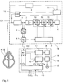
- FIG. 1 illustrates the structure of an extracorporeal control device 14 in cooperation with a programmable cardiac pacemaker 15.
- a programmable cardiac pacemaker 15 Of the two devices, only the modules related to the invention are shown; especially the conventional other components of a pacemaker are assumed to be known and are therefore not shown here.
- the shown pacemaker 15 works on the demand principle, i.e. it only sends stimulation impulses to the heart if the heart itself does not beat or does not beat sufficiently quickly.
- the pacemaker 15 therefore has an electrode E connected to the cardiac tissue H, which is connected to an anti-aliasing filter 1 for processing the input signal.
- this electrode is used to deliver stimulation pulses and is therefore additionally connected to the output of a pulse generator 16.
- the output signal of the anti-aliasing filter is fed to an amplifier 2, which amplifies the input signal by a factor of 32.
- the amplifier 2 is followed by a transmission element 3 with a plurality of filter elements 3a, 3b, 3c with adjustable cut-off frequencies f 1 , f 2 , f 2 , which by setting the Limit frequencies f 1 , f 2 , f 3 allow adaptation of the intracardially removed input signal to a downstream detector device 4. In this way, interference signals can be filtered out, which are recorded together with the heart signals via the electrode.
- the transmission element 3 has a plurality of control inputs via which the cut-off frequencies of the individual filter elements 3a, 3b, 3c can be set.
- the detector device 4 connected downstream of the transmission element 3 comprises as its main component a bipolar threshold value element which compares the amplified and filtered input signal with a positive and a negative threshold value and, in certain circumstances, detects a natural heartbeat when the positive threshold value is exceeded or the negative threshold value is undershot.
- the signal detector 4 additionally evaluates the time sequence and the duration of the threshold value violations in order to prevent incorrect detection when the signal level is shifted, for example due to an electrode shift in the body of the pacemaker wearer, with the result that the threshold value is permanently exceeded or undershot.
- the detector device 4 detects a natural heartbeat in the manner described above, this leads to an inhibition of the pulse generator 16, which otherwise stimulates with a predetermined stimulation frequency (see below). This means that the pulse generator 16 resets its internal clock generator and thus only emits a stimulation pulse if no further natural heartbeat is detected within a predetermined period of time after the detection.
- a body sensor S (shown here outside of the heart) is used to determine the stimulation frequency according to the patient's current hemodynamic requirement (which can be implemented, for example, as an intrathoracically arranged impedance measurement probe).
- Whose measurement signal is fed to an integrated amplifier and filter module 8, where signal processing takes place, and from there it arrives at a processing unit 9, which calculates the stimulation rate of the pacemaker and controls pulse generator 16 accordingly, likewise in a known manner, from the processed body signal.
- the pacemaker 15 enables the transmission of an intracardiac electrocardiogram (also referred to as "IECG”) and the signals from the body sensor S to an extracorporeal control device 14.
- IECG intracardiac electrocardiogram
- a two-channel analog / digital converter 5 is therefore connected to the input channel, which first converts the filtered input signal from the pacemaker and the measurement signal from the body sensor S into a digital data word, which is followed by digital data transmission to the extracorporeal Control device 14 allows.
- the pacemaker 15 has a telemetry unit 6.1, which enables both transmitting and receiving operation.
- transmission mode the IECG received via electrode E and / or the signal from body sensor S is transmitted to extracorporeal control device 14, while in reception mode Programming signals for setting the operating parameters of the pacemaker 15 are received.
- a programming option relates to the transfer function of the transfer element 3, which enables the detector device 4 to be adapted externally to the input signal received via the electrode by programming the desired transfer function.
- the extracorporeal control device 14 also has a telemetry unit 6.2 which enables the reception of the IECG and - in the transmission mode - the programming of the pacemaker 15.
- the extracorporeal control device 14 has a recursive digital filter system 10 of the second order, which enables filtering of the intracardiac EKG signal with a variable filter characteristic.
- the filter characteristic can be changed within wide limits by setting the filter coefficients c i .
- the output signal of this digital filter 10 is fed within the control device 14 to a detector or processing device 11 which has the same detection behavior as the detector device 4 located in the pacemaker 15.
- the control device 14 has a control unit 13, into which the attending physician enters the filter coefficients c i and thus determines the filter characteristics of the digital filter 10.
- the control unit 13 programs these filter coefficients c i into the digital filter 10 so that the attending physician can use the output signal of the detector device 11 to assess the effects of the filter settings on the detection behavior of the pacemaker.
- An indicator lamp 12 is shown in the figure as a means of checking the detection behavior, which indicates the detection of a cardiac action. In practice, of course, a refined preparation and also storage of the respective detection result will take place in order to be able to compare the effect of different filter settings.
- a filter and amplifier unit 17 is connected to the output of the second telemetry unit 6.2, to which the signal from the body sensor S (which is identified by coding in the transmission) is supplied by the telemetry unit.
- the transmission curve corresponds to that of module 8 in the pacemaker 15, so that the influencing of the body (eg impedance) signal in its signal processing path can also be simulated externally.
- a further display unit 18 is connected to the output of the filter and amplifier unit 17, on which the signal corresponding to the input signal of the processing unit 9 of the pacemaker can be displayed externally.
- Means for setting the transmission parameters of the assembly 8 are not shown in the figure, but can be provided and used in a similar manner to that described for the filter 10.
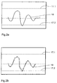
- FIG. 2b An exemplary signal curve for the output signal 19 of the digital filter 10 is shown in FIG. 2b.
- the threshold values of the downstream threshold element 11 are represented by horizontal dashed lines 17.1, 17.2. With this signal curve, the threshold value element 11 detects a cardiac event, since the lower threshold value 17.2 is not reached.
- the control unit 13 uses this to calculate which values of the cut-off frequencies f 1 , f 2 , f 3 are to be programmed, so that the second transmission element 3 located in the pacemaker 15 optimally reproduces this previously determined filter characteristic .
- the values determined in this way are then transmitted from the telemetry unit 6.2 to a control unit 7 located in the pacemaker 15, which adjusts the three filter elements 3a, 3b, 3c accordingly, so that the pacemaker 15 exhibits optimal detection behavior.
- a control unit 7 located in the pacemaker 15, which adjusts the three filter elements 3a, 3b, 3c accordingly, so that the pacemaker 15 exhibits optimal detection behavior.
- After programming these cut-off frequencies f 1 , f 2 , f 3 then shows the output signal of the second transmission element 3, the course 18 shown in FIG. 2a, which, apart from the lack of discretization, corresponds to the course shown in FIG. 2b, which is simulated by the extracorporeal control device 14.
- the embodiment of the invention is not limited to the preferred exemplary embodiments specified above. Rather, a number of variants are conceivable which make use of the solution shown, even in the case of fundamentally different types.
Abstract
Description
Die Erfindung betrifft eine extrakorporale Vorrichtung zur Benutzung mit einem implantierbaren medizinischen Gerät, insbesondere einem Herzschrittmacher, Defibrillator oder Kardioverter, gemäß dem Oberbegriff des Anspruchs 1.The invention relates to an extracorporeal device for use with an implantable medical device, in particular a pacemaker, defibrillator or cardioverter, according to the preamble of
Der Aufbau eines modernen, mittels eines Programmiergerätes auf die individuellen Bedingungen eines Patienten anpaßbaren medizinischen Geräts gestattet es üblicherweise, Signale aus dem Körperinneren aufzunehmen. Dabei kann es sich einerseits um Signale handeln, welche als solche möglichst unverfälscht vom Meßort übertragen werden sollen, oder aber um Signale, welche das Betriebsverhalten des implantierbaren Geräts beeinflussen. Diese Signale werden durch Signalübertragungsmittel beeinflußt, welche innerhalb des Verarbeitungsteils des implantierbaren Geräts vorgesehen und der Telemetriestufe vor- bzw. nachgeschaltet sind.The construction of a modern medical device which can be adapted to the individual conditions of a patient by means of a programming device usually allows signals to be recorded from inside the body. On the one hand, these can be signals which are to be transmitted as pure as possible from the measurement site, or signals which influence the operating behavior of the implantable device. These signals are influenced by signal transmission means which are provided within the processing part of the implantable device and are connected upstream or downstream of the telemetry stage.
So ist bei einem modernen Herzschrittmacher in der Regel die Übertragung der elektrischen Aktionspotentiale des Herzens in Form des intrakardialen Elektrokardiogramms an ein extrakorporales Gerät zum Zwecke der Auswertung und/oder Aufzeichnung vorgesehen.In modern pacemakers, for example, the transmission of the electrical action potentials of the heart in the form of the intracardiac electrocardiogram to an extracorporeal device is provided for the purpose of evaluation and / or recording.
Die in dem intrakardialen EKG repräsentierten Aktionssignale des Herzens werden durch ein für den normalen Betrieb des Herzschrittmachers vorgesehenes Eingangsfilter aufgenommen und danach weiterverarbeitet. Aufgrund der Übertragungseigenschaften des Eingangsfilters des Herzschrittmachers, insbesondere durch den Frequenzgang des Filters, werden die Aktionssignale des Herzens in erheblichem Maße verändert, so daß sie bei der Auswertung in einem EKG-Analysengerät keine sichere Diagnose zulassen.The action signals of the heart represented in the intracardiac EKG are recorded by an input filter provided for the normal operation of the pacemaker and then processed further. Due to the transmission properties of the input filter of the pacemaker, in particular due to the frequency response of the filter, the action signals of the heart are changed to a considerable extent, so that they do not allow a reliable diagnosis when evaluated in an EKG analysis device.
Aus DE--A-2 545 802 ist ein Herzsignaldiskriminator bekannt, der zur Unterdrückung von Störsignalen dient, welche gleichzeitig mit dem Herzaktionssignal erfaßt werden. Der Herzsignaldiskriminator weist Mittel auf, durch die die erfaßten Signale gleichgerichtet und gleichzeitig bedämpft werden.A cardiac signal discriminator is known from DE-A-2 545 802 which serves to suppress interference signals which are detected simultaneously with the cardiac action signal. The cardiac signal discriminator has means by which the detected signals are rectified and attenuated at the same time.
Aus EP-A- 0 012 709 ist weiterhin eine digital gesteuerte Amplitudenregeleinrichtung für elektrokardiographische Signale bekannt. Die vorgeschlagene Regeleinrichtung weist Mittel auf, welche den Übertragungsfaktor jeweils auf das Erscheinen eines Impulssignals (QRS-Komplex) hin nach Vergleich der Signalamplitude mit einem Schwellwert jeweils um eine Stufe vergrößern oder verkleinern.From EP-A-0 012 709 a digitally controlled amplitude control device for electrocardiographic signals is also known. The proposed control device has means which increase or decrease the transmission factor by one level each time a pulse signal (QRS complex) appears after comparing the signal amplitude with a threshold value.
Die aus den genannten Druckschriften bekannten Schaltungsanordnungen beziehen sich im wesentlichen auf eine Anpassung der Amplitude der intrakardialen Signale, um Störsignale in ihrer Wirksamkeit zumindest einzuschränken. Dies ist erforderlich, da die Amplitude dieser sogenannten Artefakte das kardiale Nutzsignal häufig um das Hundertfache übertrifft.The circuit arrangements known from the cited documents essentially relate to an adaptation of the amplitude of the intracardiac signals in order at least to limit the effectiveness of interference signals. This is necessary because the amplitude of these so-called artifacts often exceeds the cardiac useful signal by a hundred times.
In DD-A-295 995 wird eine Schaltungsanordnung zur Eliminierung von Herzschrittmacherimpulsanteilen aus EKG-Ableitungen beschrieben, mit der (Oberflächen-)EKG-Signale duch geeignete Filterung am Ausgang des EKG-Verstärkers von Schrittmacherimpulsanteilen befreit werden können.DD-A-295 995 describes a circuit arrangement for eliminating pacemaker pulse components from ECG leads, with which (surface) ECG signals can be freed from pacemaker pulse components by suitable filtering at the output of the EKG amplifier.
DE-A-3 701 947 beschreibt ein Verfahren zur Erfassung eines Oberflächen-EKG, bei dem eine zuverlässige Verarbeitung der Herzaktionssignale auch bei Schrittmacherträgern dadurch gesichert werden soll, daß die Betriebsparameter des Schrittmachers mittels einer drahtlosen Signalübertragungseinrichtung ausgelesen und dann bei der Verarbeitung des Oberflächen-EKG berücksichtigt werden.DE-A-3 701 947 describes a method for acquiring a surface ECG, in which reliable processing of the cardiac action signals is also to be ensured for pacemaker wearers in that the operating parameters of the pacemaker are established by means of a wireless signal transmission device read out and then taken into account when processing the surface ECG.
In US-A-5 421 830 wird ein Programmierungssystem für einen Schrittmacher oder Kardioverter/Defibrillator mit Mitteln zur Aufzeichnung und Analyse eines intrakardial aufgenommenen Herzsignals beschrieben, bei dem neben Mitteln zur Speicherung und Wiedergabe der Herzsignale auch eine Simulation des Ansprechens des implantierten Gerätes auf diese vorgesehen ist.US Pat. No. 5,421,830 describes a programming system for a pacemaker or cardioverter / defibrillator with means for recording and analyzing an intracardially recorded heart signal, in which, in addition to means for storing and reproducing the heart signals, a simulation of the response of the implanted device to it is also simulated is provided.
Die vorbekannten Schaltungsanordnungen lösen jedoch nicht das Problem, daß das intrakardiale EKG durch das Eingangsfilter des Herzschrittmachers verfälscht wird. Es ist deshalb zwar möglich, das intrakardiale EKG über einen Telemetriesender zur differenzierten Auswertung bzw. Speicherung an ein extrakorporales Kontrollgerät zu übertragen. Der diagnostische Wert dieses intrakardialen EKGs wie auch seine Brauchbarkeit für eine etwaige Simulation des Ansprechens des Herzschrittmachers ist jedoch durch die signalbeeinflussende Wirkung des in dem Herzschrittmacher angeordneten Eingangsfilters bzw. ggfs. anderer Übertragungsglieder stark herabgesetzt.However, the known circuit arrangements do not solve the problem that the intracardiac EKG is distorted by the input filter of the pacemaker. It is therefore possible to transmit the intracardiac EKG to an extracorporeal control device via a telemetry transmitter for differentiated evaluation or storage. However, the diagnostic value of this intracardiac EKG as well as its usefulness for a possible simulation of the response of the pacemaker is greatly reduced by the signal-influencing effect of the input filter arranged in the pacemaker or possibly other transmission elements.
Darüberhinaus besteht bei den vorbekannten Schaltungsanordnungen das Problem, daß das intrakardiale EKG stromabwärts des Punktes, an dem es zur Zuführung an die Telemetrieeinheit abgeggriffen wurde, durch Verstärker und Filter weiter beeinflußt wird, bevor das auf diese Weise aufbereitete Signal einer Detektoreinrichtung, etwa einem Schwellwertdetektor, bzw. einer Verarbeitungseinheit zugeführt wird. Das an dem extrakorporalen Gerät zur Verfügung stehende Signal unterscheidet sich deshalb von dem im Herzschrittmacher am Eingang der Detektor- bzw. Verarbeitungseinrichtung anliegenden Signal, so daß die Auswertung des telemetrisch übertragenen Signals keine verläßliche Aussage über das Detektions- bzw. Verarbeitungsverhalten des Herzschrittmachers ermöglicht.In addition, there is the problem with the known circuit arrangements that the intracardiac EKG downstream of the point at which it was tapped for delivery to the telemetry unit is further influenced by amplifiers and filters before the signal of a detector device, such as a threshold value detector, which has been processed in this way is further processed. or a processing unit is supplied. The signal available on the extracorporeal device therefore differs from that in the pacemaker on Input of the detector or processing device present signal, so that the evaluation of the telemetrically transmitted signal does not allow a reliable statement about the detection or processing behavior of the pacemaker.
Die oben angesprochenen Probleme bestehen auch hinsichtlich der externen Analyse sonstiger Körpersignale, die von einem im Verarbeitungskanal liegenden Abgriffspunkt in einem implantierten medizinischen Gerät nach außen übermittelt werden, so etwa auch für die körperliche Aktivität eines Patienten charakterisierende Signale.The problems mentioned above also exist with regard to the external analysis of other body signals which are transmitted to the outside from a tap point in the processing channel in an implanted medical device, for example also signals which characterize the physical activity of a patient.
Der Erfindung liegt somit die Aufgabe zugrunde, eine extrakorporale Vorrichtung zur Benutzuung mit einem implantierbaren elektromedizinischen Gerät zu schaffen, die eine möglichst unverfälschte Bereitstellung und ggfs. in Bezug auf die Funktion das implantierten Gerätes aussagekräftige Weiterverarbeitung intrakorporal erfaßter Signale außerhalb des Körpers ermöglicht.The invention is therefore based on the object of providing an extracorporeal device for use with an implantable electromedical device which enables the most genuine possible provision and, if necessary, meaningful further processing of intracorporeally detected signals outside the body with regard to the function of the implanted device.
Die Aufgabe wird durch eine Vorrichtung mit den Merkmalen des Anspruchs 1 gelöst.The object is achieved by a device having the features of
Die Erfindung schließt die technische Lehre ein, bei der extrakorporalen Vorrichtung zum einen die durch ein vor dem Abgriffspunkt des Signals liegendes Übertragungsglied - etwa das Eingangsfilter eines Herzschrittmachers - verursachte Signalbeeinflussung zu kompensieren, um ein unverfälschtes Signal zu erhalten, und ggfs. zum anderen die in dem implantierten Gerät zwischen dem Signalabgriffspunkt und dem eigentlichen Detektor bzw. der Verarbeitungseinheit erfolgende Signalbeeinflussung durch Verstärker und Filter zu simulieren, um extern das gesamte Detektionsverhalten des implantierten Gerätes nachbilden zu können.The invention includes the technical teaching in the case of the extracorporeal device, on the one hand, to compensate for the signal influence caused by a transmission element located in front of the tapping point of the signal, for example the input filter of a pacemaker, in order to obtain an unadulterated signal, and, on the to the implanted device between the signal tapping point and the actual detector or the processing unit, the signal is influenced by amplifiers and filters simulate in order to be able to simulate the entire detection behavior of the implanted device externally.
Der Begriff "Eingangssignal" ist im folgenden in einem allgemeinen Sinne zu verstehen: Besonders vorteilhaft ist die Erfindung auf natürliche (spontane) Herzaktionssignale, d.h. bei der externen Verarbeitung intrakardialer EKGs, anwendbar. Die Anwendung der Erfindung ist jedoch auch bei Körpersignalen mit Vorteil möglich, die die Aktivität des Herzschrittmacherträgers widerspiegeln, wie beispielsweise intrathorakal oder intrakardial erfaßten Impedanzsignalen. Sie ist jedoch hierauf nicht beschränkt, sondern prinzipiell für alle aus dem internen Verarbeitungskanal eines implantierten Gerätes nach außen übermittelten Signale anwendbar.The term "input signal" is to be understood in the following in a general sense: The invention is particularly advantageous for natural (spontaneous) heart action signals, i.e. applicable for external processing of intracardiac EKGs. However, the application of the invention is also advantageously possible with body signals that reflect the activity of the pacemaker wearer, such as, for example, intrathoracically or intracardially detected impedance signals. However, it is not limited to this, but can in principle be used for all signals transmitted to the outside from the internal processing channel of an implanted device.
Bei einem Herzschrittmacher ist das erste in dem Eingangskanal angeordnete Übertragungsglied in der Regel ein Eingangsfilter, das beispielsweise als Anti-Aliasing-Filter ausgeführt ist.In the case of a pacemaker, the first transmission element arranged in the input channel is generally an input filter, which is designed, for example, as an anti-aliasing filter.
Das zweite Übertragungsglied besteht in der Regel aus einem Verstärker mit programmierbarer Verstärkung, der durch eine Einstellung der Verstärkung die Anpassung des Signaldetektors an den elektrischen Pegel des Eingangssignals ermöglicht, bzw. einer entsprechend programmierbaren Veratärker-Filter-Baugruppe.The second transmission element usually consists of an amplifier with programmable amplification, which, by adjusting the amplification, enables the signal detector to be adapted to the electrical level of the input signal, or a correspondingly programmable amplifier filter module.
Die Übertragungsglieder können auch jeweils aus mehreren einzelnen Bauelementen bestehen.The transmission elements can also consist of several individual components.
Herzschrittmacher, mit denen Ausführungen des erfindungsgemaßen Gerätes vorteilhaft einsetzbar sind, weisen zur Übertragung des Körpersignals (speziell inrakardialen EKGs) nach außerhalb des Körpers einen Telemetriesender auf, der vor dem zweiten Übertragungsglied und/oder nach dem ersten Übertragungsglied mit dem Verarbeitungsskanal verbunden ist. In der Regel ist dieser Telemetriesender Bestandteil einer Telemetrieeinheit des Schrittmachers, die sowohl Sende- als auch Empfangsbetrieb erlaubt, wobei im Sendebetrieb eine Übertragung der von dem Herzschrittmacher aufgenommenen Signale erfolgt, während der Empfangsbetrieb eine Programmierung des Herzschrittmachers durch das extrakorporale Kontrollgerät ermöglicht.Pacemakers, with which versions of the device according to the invention can advantageously be used, have for transmitting the body signal (especially inracardial EKGs) to the outside of the body on a telemetry transmitter which is connected to the processing channel before the second transmission element and / or after the first transmission element. As a rule, this telemetry transmitter is part of a telemetry unit of the pacemaker, which allows both transmitting and receiving mode, the signals recorded by the pacemaker being transmitted in the transmitting mode, while the receiving mode enables the pacemaker to be programmed by the extracorporeal control device.
Wenn der Schrittmacher nur ein Übertragungsglied aufweist, erfolgt der Signalabgriff für den Telemetriesender also entweder stromaufwärts oder stromabwärts dieses Übertragungsgliedes.If the pacemaker has only one transmission element, the signal is tapped for the telemetry transmitter either upstream or downstream of this transmission element.
Weist der Herzschrittmacher dagegen zwei oder mehrere Übertragungsglieder auf (was in der Praxis die Regel ist), so erfolgt der Signalabgriff zwischen den Übertragungsgliedern.If, on the other hand, the pacemaker has two or more transmission elements (which is the rule in practice), the signal is tapped between the transmission elements.
Die erfindungsgemäße Vorrichtung weist in einer auf implantierte Geräte mit Signalabgriff nach einem Übertragungsglied zugeschnittenen Ausführung, dem Telemetrieempfänger nachgeschaltet, ein drittes Übertragungsglied auf, das die Aufgabe hat, die Signalbeeinflussung durch das dem Telemetriesender vorgeschaltete erste Übertragungsglied - in der Regel das Eingangsfilter - zu kompensieren, um das unverfälschte Eingangssignal zur Verfügung zu stellen. Dies ist besonders vorteilhaft bei der Aufnahme und Übertragung eines intrakardialen EKGs als Eingangssignal, da ein unverfälschtes EKG für den behandelnden Arzt einen wesentlich großeren diagnostischen Wert hat, als die mit bekannten Kontrollgeräten ermittelten, durch das Eingangsfilter des Herzschrittmachers verzerrten EKG-Signale. Das dritte Übertragungsglied weist deshalb insbesondere eine gegenüber dem ersten Übertragungsglied exakt inverse Übertragungsfunktion auf, um dessen signalbeeinflussende Wirkung möglichst vollständig kompensieren zu können.The device according to the invention has, in an embodiment tailored to implanted devices with signal tapping after a transmission link, downstream of the telemetry receiver, a third transmission link which has the task of compensating for the signal influence by the first transmission link upstream of the telemetry transmitter - as a rule the input filter. to provide the unadulterated input signal. This is particularly advantageous when recording and transmitting an intracardiac EKG as an input signal, since an unadulterated ECG has a much greater diagnostic value for the attending physician than that with known ones Control devices determined EKG signals distorted by the input filter of the pacemaker. The third transmission element therefore has, in particular, a transmission function which is exactly inverse with respect to the first transmission element in order to be able to compensate for its signal-influencing effect as completely as possible.
Weist das erste Übertragungsglied im Herzschrittmacher beispielsweise die komplexe Übertragungsfunktion c 1 (f) auf, so berechnet sich das Telemetriesignal TS(f) aus dem Eingangssignal ES(f) nach der Formel:![]()
![]()
Das Ausgangssignal AS(f) des dritten Übertragungsglieds mit der komplexen Übertragungsfunktion c 3 (f) errechnet sich dann aus dem Telemetriesignal TS(f):![]()
![]()
Die Übertragungsfunktion c 3 (f) muß hierbei so gewählt werden, daß das Ausgangssignal TS(f) des dritten Übertragungsglieds das Eingangssignal möglichst unverfälscht wiedergibt. Hieraus ergibt sich die Forderung:![]()
![]()
Bei implantierten Geräten mit Signalabgriff vor weiteren Übertragungsgliedern unterscheidet sich das am Ausgang der stromabwärts vom Abgriffspunkt vorgesehenen Übertragungsglieder (hier als "zweites Übertragungsglied" subsumiert) erscheinende Signal von dem telemetrisch übertragenen Signal. Eine Modellierung des Schrittmacherverhaltens wird aber dennoch dadurch ermöglicht, daß die Übertragungsfunktion dieses Gliedes gemäß einem Aspekt der Erfindung auch im externen Gerät auf das dort vorliegende Signal angewandt wird. Das extern angeordnete dritte Übertragungsglied (unter diesen Begriff werden hier wiederum ggfs. mehrere in der extrakorporalen Vorrichtung vorgesehene Übertragungsglieder gefaßt) weist deshalb in dieser Variante der Erfindung insbesonere exakt die gleiche Übertragungsfunktion wie das hinter dem Telemetriesender angeordnete zweite Übertragungsglied auf.In implanted devices with signal tapping in front of further transmission elements, the signal appearing at the output of the transmission elements provided downstream of the tapping point (subsumed here as "second transmission element") differs from the telemetrically transmitted signal. A modeling of the pacemaker behavior is nevertheless made possible by the fact that the transfer function this link according to one aspect of the invention is also applied in the external device to the signal present there. In this variant of the invention, the externally arranged third transmission element (this term in turn here may include several transmission elements provided in the extracorporeal device) in particular has exactly the same transmission function as the second transmission element arranged behind the telemetry transmitter.
In einer praktisch besonders bedeutsamen Fortbildung dieser Variante ermöglicht das Vorsehen von Mitteln zur Einstellung verschiedener Übertragungsfunktionen des dritten Übertragungsgliedes eine Modellierung des Schrittmacherverhaltens für verschiedene Einstellungen des zweiten Übertragungsglieds, ohne den Herzschrittmacher selbst umprogrammieren zu müssen.In a practically particularly important development of this variant, the provision of means for setting different transfer functions of the third transfer link enables the pacemaker behavior to be modeled for different settings of the second transfer link without having to reprogram the pacemaker itself.
Wie bereits vorstehend erläutert, weist das in dem Herzschrittmacher angeordnete zweite Übertragungsglied in der Regel einen programmierbaren Verstärker auf, der eine Anpassung der nachgeschalteten Detektor- bzw. Verarbeitungseinrichtung an den Pegel der erfaßten Herzsignale ermöglicht. Dies ist wichtig, da der Pegel der von dem Herzschrittmacher erfaßten Herzsignale von der Lage der Elektroden, dem Widerstand des Körpergewebes und anderen Faktoren abhängt und somit Schwankungen unterliegt, die durch eine Einstellung der Eingangsverstärkung berücksichtigt werden müssen.As already explained above, the second transmission element arranged in the cardiac pacemaker generally has a programmable amplifier which enables the downstream detector or processing device to be adapted to the level of the cardiac signals detected. This is important because the level of the cardiac signals sensed by the pacemaker depends on the position of the electrodes, the resistance of the body tissue and other factors and is therefore subject to fluctuations which have to be taken into account by adjusting the input gain.
Bei vorbekannten Schrittmachersystemen erfolgt diese Einstellung in der Regel, indem der behandelnde Arzt nacheinander verschiedene Eingangsverstärkungen programmiert und anhand von Sense-Markern oder aufgrund des Schrittmacherverhaltens beurteilt, ob der Schrittmacher ein vom Herz geliefertes Signal erkennt oder nicht ("Sensingtest"). Problematisch ist hierbei, daß sich die während des Tests vorgenommenen Einstellungen der Eingangsverstärkung bereits auf das Schrittmacherverhalten auswirken, was während des Tests oftmals unerwünscht ist. So werden bei zu hoher Eingangsempfindlichkeit bereits Störsignale fehlerhaft als Herzaktionen detektiert, so daß während des Tests eventuell eine an sich erforderliche Stimulation ausbleibt. Ist die Eingangsempfindlichkeit dagegen zu gering, so werden die spontanen Herzaktionen nicht detektiert, und der Herzschrittmacher stimuliert während des Tests ständig, obwohl das Herz selbst hinreichend schnell schlägt.In the case of previously known pacemaker systems, this setting is generally carried out by the attending doctor programming and programming various input amplifications in succession judged on the basis of sense markers or on the basis of the pacemaker behavior whether the pacemaker recognizes a signal delivered by the heart or not (“sensing test”). The problem here is that the input gain settings made during the test already affect the pacemaker behavior, which is often undesirable during the test. If the input sensitivity is too high, interfering signals are already incorrectly detected as heart actions, so that during the test there may be no stimulation per se. If, on the other hand, the input sensitivity is too low, the spontaneous cardiac actions are not detected and the pacemaker constantly stimulates during the test, even though the heart beats sufficiently fast.
Ein weiterer Nachteil der vorbekannten Schrittmachersysteme ist darin zu sehen, daß der Arzt bei der Programmierung des Schrittmachers in der Regel eine höhere Eingangsempfindlichkeit einstellt als tatsächlich erforderlich ist, um auch bei Intensitätsschwankungen der Herzsignale ein Herzereignis sicher erkennen zu können. Dies führt jedoch dazu, daß der Eingangsverstärker des Herzschrittmachers bei einem Herzereignis mit normaler Intensität in die Sättigung gerät, so daß die Amplitude dieses Herzereignisses nicht mehr bestimmt werden kann.A further disadvantage of the previously known pacemaker systems is that the doctor generally sets a higher input sensitivity when programming the pacemaker than is actually required in order to be able to reliably detect a cardiac event even in the event of fluctuations in the intensity of the cardiac signals. However, this leads to the fact that the input amplifier of the pacemaker saturates during a cardiac event with normal intensity, so that the amplitude of this cardiac event can no longer be determined.
In einer vorteilhaften Variante der Erfindung ist dem dritten Übertragungsglied deshalb eine Detektoreinrichtung nachgeschaltet, die im wesentlichen das gleiche Detektionsverhalten aufweist wie diejenige des Schrittmachers. Das Übertragungsverhalten des dritten Übertragungsglieds ist hierbei einstellbar, um die Übertragungsfunktion zu ermitteln, die ein optimales Detektionsverhalten ermöglicht. Da die Einstellung hierbei in der extrakorporalen Vorrichtung erfolgt und nicht - wie bei bekannten Schrittmachersystemen - im Schrittmacher selbst, wird das Schrittmacherverhalten während des Tests nicht beeinflußt. Erst nach Ermittlung der optimalen Einstellung wird diese vom externen Gerät telemetrisch an den programmierbaren Herzschrittmacher übertragen und eingestellt. Vorzugsweise besteht das dritte Übertragungsglied hierbei aus einem digitalen Filter, dessen Filtercharakteristik durch Vorgabe mehrerer Filterkoeffizienten einstellbar ist.In an advantageous variant of the invention, the third transmission element is therefore followed by a detector device which has essentially the same detection behavior as that of the pacemaker. The transmission behavior of the third transmission element is adjustable in order to determine the transmission function that enables an optimal detection behavior. There the setting is made in the extracorporeal device and not - as in known pacemaker systems - in the pacemaker itself, the pacemaker behavior is not influenced during the test. Only after the optimum setting has been determined is this telemetrically transmitted and set by the external device to the programmable pacemaker. In this case, the third transmission element preferably consists of a digital filter, the filter characteristics of which can be set by specifying a plurality of filter coefficients.
Die extrakorporale Vorrichtung kann in zweckmäßigen Ausführungen als spezielles Kontrollgerät für ein implantiertes Gerät (insbesondere einen Herzschrittmacher, Defibrillator und/oder Kardioverter), als Baugruppe eines Programmiergerätes für derartige implantierte Geräte oder eines Körpersignal-Analysengerätes (etwa eines EKG- oder EEG-Gerätes) oder auch als - insbesondere programmierbare - Schnittstelle ausgebildet sein, über die ein herkömmliches Programmier- oder Analysegerat auf wesentlich funktionserweiternde Weise mit einem implantierten Gerät verbindbar ist.The extracorporeal device can be used as a special control device for an implanted device (in particular a pacemaker, defibrillator and / or cardioverter), as a module of a programming device for such implanted devices or a body signal analysis device (such as an EKG or EEG device) or also be designed as an - in particular programmable - interface via which a conventional programming or analysis device can be connected to an implanted device in a substantially function-expanding manner.
Andere vorteilhafte Weiterbildungen der Erfindung sind in den Unteransprüchen gekennzeichnet bzw. werden nachstehend zusammen mit der Beschreibung der bevorzugten Ausführung der Erfindung anhand der Figuren näher dargestellt. Es zeigen:
Figur 1 als bevorzugtes Ausführungsbeispiel der Erfindung ein extrakorporales Kontrollgerät für einen implantierbaren Schrittmacher als Blockschaltbild,- Figur 2a einen exemplarischen Signalverlauf für das in dem Herzschrittmacher aufbereitete intrakardiale Herzsignal sowie
- Figur 2b das entsprechende Signal in dem extrakorporalen Kontrollgerät nach Fig. 1 in digitalisierter Form.
- 1 as a preferred exemplary embodiment of the invention, an extracorporeal control device for an implantable pacemaker as a block diagram,
- Figure 2a shows an exemplary signal curve for the intracardiac cardiac signal processed in the pacemaker and
- 2b shows the corresponding signal in the extracorporeal control device according to FIG. 1 in digitized form.
Das in Figur 1 gezeigte Blockschaltbild verdeutlicht den Aufbau eines extrakorporalen Kontrollgeräts 14 im Zusammenwirken mit einem programmierbaren Herzschrittmacher 15. Von beiden Geräten sind nur die in Bezug zur Erfindung stehenden Baugruppen dargestellt; speziell die herkömmlichen übrigen Baugruppen eines Schrittmachers werden als bekannt vorausgesetzt und sind daher hier nicht gezeigt.The block diagram shown in FIG. 1 illustrates the structure of an
Der dargestellte Herzschrittmacher 15 arbeitet nach dem Demand-Prinzip, d.h. er gibt Stimulationsimpulse nur dann an das Herz ab, wenn dieses selbst nicht oder nicht hinreichend schnell schlägt. Zur Detektion von Herzsignalen weist der Herzschrittmacher 15 deshalb eine mit dem Herzgewebe H verbundene Elektrode E auf, die zur Aufbereitung des Eingangssignals mit einem Anti-Aliasing-Filter 1 verbunden ist. Neben der Erfassung der spontanen Herzaktivität dient diese Elektrode zur Abgabe von Stimulationsimpulsen und ist deshalb zusätzlich mit dem Ausgang eines Impulsgenerators 16 verbunden.The shown
Das Ausgangssignal des Anti-Aliasing-Filters wird einem Verstärker 2 zugeführt, der das Eingangssignal um den Faktor 32 verstärkt.The output signal of the anti-aliasing filter is fed to an
Dem Verstärker 2 ist ein Übertragungsglied 3 mit mehreren Filterelementen 3a, 3b, 3c mit einstellbaren Grenzfrequenzen f 1 , f 2 , f 2 nachgeschaltet, das durch Einstellung der Grenzfrequenzen f 1 , f 2 , f 3 eine Anpassung des intrakardial abgenommenen Eingangssignals an eine nachgeschaltete Detektoreinrichtung 4 ermöglicht. Hierdurch können Störsignale ausgefiltert werden, die zusammen mit den Herzsignalen über die Elektrode aufgenommen werden. Zur Einstellung der Filtercharakteristik weist das Übertragungsglied 3 mehrere Steuereingänge auf, über die die Grenzfrequenzen der einzelnen Filterelemente 3a, 3b, 3c eingestellt werden können.The
Die dem Übertragungsglied 3 nachgeschaltete Detektoreinrichtung 4 umfaßt als Hauptbestandteil ein bipolares Schwellwertglied, das das verstärkte und gefilterte Eingangssignal mit einem positiven und einem negativen Schwellwert vergleicht und beim Überschreiten des positiven Schwellwerts bzw. beim Unterschreiten des negativen Schwellwerts unter bestimmten Umständen einen natürlichen Herzschlag detektiert. Der Signaldetektor 4 wertet hierbei zusätzlich die zeitliche Folge und die Dauer der Schwellwertüberschreitungen aus, um bei einer Verschiebung des Signalpegels, beispielsweise aufgrund einer Elektrodenverschiebung im Körper des Herzschrittmacherträgers mit der Folge einer dauerhaften Über- oder Unterschreitung eines Schwellwerts, eine Fehldetektion zu verhindern.The
Wenn die Detektoreinrichtung 4 auf die vorstehend beschriebene Weise einen natürlichen Herzschlag detektiert, führt dies zu einer Inhibierung des Impulsgenerators 16, der ansonsten mit vorgegebener Stimulationsfrequenz (siehe unten) stimuliert. Dies bedeutet, daß der Impulsgenerator 16 seinen internen Taktgeber zurücksetzt und somit erst dann einen Stimulationsimpuls abgibt, wenn innerhalb einer vorgegebenen Zeitspanne nach der Detektion kein weiterer natürlicher Herzschlag detektiert wird.If the
Zur Festlegung der Stimulationsfrequenz entsprechend dem aktuellen hämodynamischen Bedarf des Patienten dient ein - hier außerhalb des Herzens dargestellter - Körperfühler S (der beispielsweise in an sich bekannter Weise als intrathorakal angeordnete Impedanzmeßsonde ausgeführt sein kann). Dessen Meßsignal wird einer integrierten Verstärker- und Filterbaugruppe 8 zugeführt, wo eine Signalaufbereitung erfolgt, und gelangt von dort zu einer Verarbeitungseinheit 9, die aus dem aufbereiteten Körpersignal - ebenfalls in bekannter Weise - die Stimulationsrate des Schrittmachers errechnet und den Impulsgenerator 16 entsprechend steuert.A body sensor S (shown here outside of the heart) is used to determine the stimulation frequency according to the patient's current hemodynamic requirement (which can be implemented, for example, as an intrathoracically arranged impedance measurement probe). Whose measurement signal is fed to an integrated amplifier and
Neben der vorstehend beschriebenen herkömmlichen Funktionsweise als ratenadaptiver Demand-Schrittmacher ermöglicht der Herzschrittmacher 15 die Übertragung eines intrakardialen Elektrokardiogramms (auch als "IECG" bezeichnet) sowie der Signale des Körperfühlers S an ein extrakorporales Kontrollgerät 14.In addition to the conventional functioning described above as a rate-adaptive demand pacemaker, the
Stromabwärts des Anti-Aliasing-Filters 1 ist deshalb ein zweikanaliger Analog/Digital-Wandler 5 an den Eingangskanal angeschlossen, der das gefilterte Eingangssignal des Herzschrittmachers sowie das Meßsignal des Körperfühlers S zunächst in ein digitales Datenwort umwandelt, was eine anschließende digitale Datenübertragung an das extrakorporale Kontrollgerät 14 ermöglicht.Downstream of the
Hierzu weist der Schrittmacher 15 eine Telemetrieeinheit 6.1 auf, die sowohl Sende- als auch Empfangsbetrieb ermöglicht. Im Sendebetrieb wird das über die Elektrode E aufgenommene IECG und/oder das Signal des Korperfühlers S an das extrakorporale Kontrollgerät 14 übertragen, während im Empfangsbetrieb Programmiersignale zur Einstellung der Betriebsparameter des Herzschrittmachers 15 empfangen werden.For this purpose, the
Eine Programmiermöglichkeit betrifft hierbei die Übertragungsfunktion des Übertragungsglieds 3, was eine externe Anpassung der Detektoreinrichtung 4 an das über die Elektrode aufgenommene Eingangssignal ermöglicht, indem die gewünschte Übertragungsfunktion programmiert wird.A programming option relates to the transfer function of the transfer element 3, which enables the
Entsprechend weist auch das extrakorporale Kontrollgerät 14 eine Telemetrieeinheit 6.2 auf, die den Empfang des IECG sowie - im Sendebetrieb - die Programmierung des Herzschrittmachers 15 ermöglicht.Correspondingly, the
Weiterhin verfügt das extrakorporale Kontrollgerät 14 über ein rekursives Digitalfiltersystem 10 zweiter Ordnung, das eine Filterung des intrakardialen EKG-Signals mit variabler Filtercharakteristik ermöglicht. Das digitale Filter 10 berechnet hierbei aus dem als Folge x1, x2,....,xi,... digitaler Abtastwerte vorliegenden intrakardialen EKG-Signal als Ausgangssignal eine Folge y1, y2,..., yi nach der Formel![]()
![]()
Die Übertragungsfunktion dieses Filters 10 errechnet sich wie folgt:
Durch Einstellung der Filterkoeffizienten ci läßt sich die Filtercharakteristik in weiten Grenzen verändern.The filter characteristic can be changed within wide limits by setting the filter coefficients c i .
Das Ausgangssignal dieses digitalen Filters 10 wird innerhalb des Kontrollgeräts 14 einer Detektor- bzw. Verarbeitungseinrichtung 11 zugeführt, die das gleiche Detektionsverhalten aufweist wie die im Schrittmacher 15 befindliche Detektoreinrichtung 4. Auf diese Weise läßt sich das Detektionsverhalten des Herzschrittmachers 15 für verschiedene Filtercharakteristiken modellieren, ohne den Herzschrittmacher selbst jeweils umprogrammieren zu müssen. Das Kontrollgerät 14 weist hierzu eine Steuereinheit 13 auf, in die der behandelnde Arzt die Filterkoeffizienten ci eingibt und somit die Filtercharakteristik des digitalen Filters 10 bestimmt. Die Steuereinheit 13 programmiert diese Filterkoeffizienten ci dann in das digitale Filter 10, so daß der behandelnde Arzt anhand des Ausgangssignals der Detektoreinrichtung 11 die Auswirkungen der Filtereinstellungen auf das Detektionsverhalten des Schrittmachers beurteilen kann. Als Mittel zur Überprüfung des Detektionsverhaltens ist in der Figur eine Anzeigelampe 12 dargestellt, die jeweils die Erfassung einer Herzaktion anzeigt. Selbstverständlich wird in der Praxis eine verfeinerte Aufbereitung und auch Speicherung des jeweiligen Detektionsergebnisses erfolgen, um die Wirkung verschiedener Filtereinstellungen vergleichen zu können.The output signal of this
Neben der einstellbaren Digitalfilterbaugruppe 10 ist mit dem Ausgang der zweiten Telemetrieeinheit 6.2 eine Filter- und Verstärkereinheit 17 verbunden, der von der Telemetrieeinheit das (bei der Übertragung durch Codierung gekennzeichnete) Signals des Körperfühlers S zugeführt wird. Deren Übertragungskurve entspricht derjenigen der Baugruppe 8 im Schrittmacher 15, so daß auch die Beeinflussung des Körper-(z.B. Impedanz-)signals in dessen Signalaufbereitungsweg extern nachgebildet werden kann. Mit dem Ausgang der Filter- und Verstärkereinheit 17 ist eine weitere Anzeigeeinheit 18 verbunden, auf der das dem Eingangssignal der Verarbeitungseinheit 9 des Schrittmachers entsprechende Signal extern dargestellt werden kann. Mittel zur Einstellung der Übertragungsparameter der Baugruppe 8 sind in der Figur nicht gezeigt, können aber auf ähnliche Weise vorgesehen sein und genutzt werden, wie dies oben für das Filter 10 beschrieben wurde.In addition to the adjustable
Ein exemplarischer Signalverlauf für das Ausgangssignal 19 des digitalen Filters 10 ist in Figur 2b dargestellt. Die Schwellwerte des nachgeschalteten Schwellwertglieds 11 sind hierbei durch waagerechte gestrichelte Linien 17.1, 17.2 dargestellt. Bei diesem Signalverlauf detektiert das Schwellwertglied 11 ein Herzereignis, da der untere Schwellwert 17.2 unterschritten wird.An exemplary signal curve for the
Wenn der Arzt auf diese Weise die optimale Filtercharakteristik gefunden hat, errechnet die Steuereinheit 13 daraus, welche Werte der Grenzfrequenzen f 1 , f 2 , f 3 zu programmieren sind, damit das in dem Herzschrittmacher 15 befindliche zweite Übertragungsglied 3 diese zuvor ermittelte Filtercharakteristik optimal nachbildet.When the doctor has found the optimal filter characteristic in this way, the
Die auf diese Weise ermittelten Werte werden dann von der Telemetrieeinheit 6.2 an eine in dem Herzschrittmacher 15 befindliche Steuereinheit 7 übertragen, die die drei Filterelemente 3a, 3b, 3c entsprechend einstellt, so daß der Herzschrittmacher 15 ein optimales Detektionsverhalten zeigt. Nach der Programmierung dieser Grenzfrequenzen f 1 , f 2 , f 3 zeigt das Ausgangssignal des zweiten Übertragungsglieds 3 dann den in Figur 2a gezeigten Verlauf 18, der bis auf die fehlende Diskretisierung mit dem in Figur 2b dargestellten, durch das extrakorporale Kontrollgerät 14 simulierten Verlauf übereinstimmt.The values determined in this way are then transmitted from the telemetry unit 6.2 to a
Die Erfindung beschränkt sich in ihrer Ausführung nicht auf die vorstehend angegebenen bevorzugten Ausführungsbeispiele. Vielmehr ist eine Anzahl von Varianten denkbar, welche von der dargestellten Lösung auch bei grundsätzlich anders gearteten Ausführungen Gebrauch macht.The embodiment of the invention is not limited to the preferred exemplary embodiments specified above. Rather, a number of variants are conceivable which make use of the solution shown, even in the case of fundamentally different types.
Claims (9)
zur Aufnahme und Verarbeitung eines, insbesondere die Funktion des implantierbaren Geräts beeinflussenden, über einen intrakorporalen Signalaufnehmer (E, S) aufgenommenen Meßsignals einen Verarbeitungskanal (1 bis 3, 8) aufweist, in dem ein erstes und/oder ein zweites signalbeeinflussendes Übertragungsglied (1, 2, 3, 8) vorgesehen ist, wobei zur Übertragung eines von dem Meßsignal abgeleiteten Telemetriesignals an das Kontrollgerät (14) eine erste Telemetrieeinheit (6.1) vorgesehen ist, deren Eingang mit dem Ausgang des ersten Übertragungsglieds (1) und/oder dem Eingang des zweiten Übertragungsglieds (3, 8) verbunden ist,
mit einer zweiten Telemetrieeinheit (6.2) zum Empfang des von dem implantierbaren Gerät(15) ausgesandten Telemetriesignals,
gekennzeichnet durch
ein der zweiten Telemetrieeinheit (6.2) nachgeschaltetes drittes Übertragungsglied (10, 17) zur Kompensation der in dem Telemetriesignal enthaltenen, durch das erste Übertragungsglied (1) bewirkten Signalbeeinflussung zwecks extrakorporalen Bereitstellung eines von dem ersten Übertragungsglied im wesentlichen unbeeinflußten Meßsignals und/oder zur Nachbildung der durch das zweite Übertragungsglied (2, 3, 8) verursachten Signalbeeinflussung des Meßsignals zwecks extrakorporaler Nachbildung des Ausgangssignals des zweiten Übertragungsglieds, insbesondere zur externen Modellierung des Verhaltens des implantierbaren Geräts in Abhängigkeit von dem Meßsignal.Extracorporeal device (14) for use with an implantable electromedical device, in particular a pacemaker (15), defibrillator or cardioverter, which
has a processing channel (1 to 3, 8) in which a first and / or a second signal-influencing transmission element (1, 3) has a processing channel (1 to 3, 8) for recording and processing a measurement signal, in particular influencing the function of the implantable device. 2, 3, 8) is provided, wherein a first telemetry unit (6.1) is provided for transmitting a telemetry signal derived from the measurement signal to the control device (14), the input of which is connected to the output of the first transmission element (1) and / or the input of the second transmission element (3, 8) is connected,
with a second telemetry unit (6.2) for receiving the telemetry signal emitted by the implantable device (15),
marked by
a third transmission element (6.2) connected downstream of the second telemetry unit (6.2) to compensate for the signal influencing contained in the telemetry signal and caused by the first transmission element (1) for the purpose of providing an extracorporeal measurement signal which is essentially unaffected by the first transmission element and / or to emulate the signal influencing of the measurement signal caused by the second transmission element (2, 3, 8) for the purpose of extracorporeal simulation of the output signal of the second transmission element, in particular for external modeling of the behavior of the implantable device as a function of the measurement signal.
daß dem dritten Übertragungsglied (10) zur extrakorporalen Detektion des intrakorporal aufgenommenen Meßsignals mindestens mittelbar eine Detektorenrichtung (11) nachgeschaltet ist, die im wesentlichen das gleiche Detektionsverhalten aufweist wie eine entsprechende Detektoreinrichtung (4) des implantierbaren Geräts (15),
daß das Übertragungsverhalten des dritten Übertragungsglieds (10) zur Anpassung des Detektionsvermögens der nachgeschalteten Detektoreinrichtung (11) veränderbar ist und
daß das zweite Übertragungsglied (2, 3) im implantierbaren Gerät (15) entsprechend der bei dem dritten Übertragungsglied vorgenommenen Einstellung fernsteuerbar ist.Device (14) according to claim 6, characterized in that
that the third transmission element (10) for extracorporeal detection of the intracorporeally recorded measurement signal is followed at least indirectly by a detector direction (11) which has essentially the same detection behavior as a corresponding detector device (4) of the implantable device (15),
that the transmission behavior of the third transmission element (10) can be changed to adapt the detection capability of the downstream detector device (11) and
that the second transmission element (2, 3) in the implantable device (15) can be remotely controlled in accordance with the setting made for the third transmission element.
Applications Claiming Priority (2)
| Application Number | Priority Date | Filing Date | Title |
|---|---|---|---|
| DE19548658A DE19548658A1 (en) | 1995-12-18 | 1995-12-18 | Extracorporeal control device for an implantable medical device |
| DE19548658 | 1995-12-18 |
Publications (3)
| Publication Number | Publication Date |
|---|---|
| EP0783902A2 true EP0783902A2 (en) | 1997-07-16 |
| EP0783902A3 EP0783902A3 (en) | 1998-10-07 |
| EP0783902B1 EP0783902B1 (en) | 2005-10-26 |
Family
ID=7781359
Family Applications (1)
| Application Number | Title | Priority Date | Filing Date |
|---|---|---|---|
| EP96250292A Expired - Lifetime EP0783902B1 (en) | 1995-12-18 | 1996-12-17 | Extracorporal control device for an implantable medical device |
Country Status (3)
| Country | Link |
|---|---|
| US (1) | US5792207A (en) |
| EP (1) | EP0783902B1 (en) |
| DE (2) | DE19548658A1 (en) |
Cited By (2)
| Publication number | Priority date | Publication date | Assignee | Title |
|---|---|---|---|---|
| WO1999007354A2 (en) * | 1997-08-08 | 1999-02-18 | Duke University | Compositions, apparatus and methods for facilitating surgical procedures |
| US6711436B1 (en) | 1997-08-08 | 2004-03-23 | Duke University | Compositions, apparatus and methods for facilitating surgical procedures |
Families Citing this family (23)
| Publication number | Priority date | Publication date | Assignee | Title |
|---|---|---|---|---|
| DE19758393B4 (en) * | 1997-12-23 | 2006-04-20 | Biotronik Meß- und Therapiegeräte GmbH & Co. Ingenieurbüro Berlin | Arrangement for patient monitoring |
| US6223083B1 (en) * | 1999-04-16 | 2001-04-24 | Medtronic, Inc. | Receiver employing digital filtering for use with an implantable medical device |
| US6535763B1 (en) | 1999-08-22 | 2003-03-18 | Cardia Pacemakers, Inc. | Event marker alignment by inclusion of event marker transmission latency in the real-time data stream |
| US6721594B2 (en) | 1999-08-24 | 2004-04-13 | Cardiac Pacemakers, Inc. | Arrythmia display |
| US6650944B2 (en) | 2000-02-23 | 2003-11-18 | Medtronic, Inc. | Follow-up monitoring method and system for implantable medical devices |
| US6665558B2 (en) | 2000-12-15 | 2003-12-16 | Cardiac Pacemakers, Inc. | System and method for correlation of patient health information and implant device data |
| US8548576B2 (en) | 2000-12-15 | 2013-10-01 | Cardiac Pacemakers, Inc. | System and method for correlation of patient health information and implant device data |
| CA2449468A1 (en) | 2001-06-04 | 2002-12-12 | Albert Einstein Healthcare Network | Cardiac stimulating apparatus having a blood clot filter and atrial pacer |
| US6823209B2 (en) * | 2001-10-19 | 2004-11-23 | Medtronic Physio-Control Corp. | Electrocardiogram filter |
| US7065409B2 (en) * | 2002-12-13 | 2006-06-20 | Cardiac Pacemakers, Inc. | Device communications of an implantable medical device and an external system |
| US7009511B2 (en) | 2002-12-17 | 2006-03-07 | Cardiac Pacemakers, Inc. | Repeater device for communications with an implantable medical device |
| US7127300B2 (en) * | 2002-12-23 | 2006-10-24 | Cardiac Pacemakers, Inc. | Method and apparatus for enabling data communication between an implantable medical device and a patient management system |
| US7395117B2 (en) * | 2002-12-23 | 2008-07-01 | Cardiac Pacemakers, Inc. | Implantable medical device having long-term wireless capabilities |
| US6978182B2 (en) * | 2002-12-27 | 2005-12-20 | Cardiac Pacemakers, Inc. | Advanced patient management system including interrogator/transceiver unit |
| US20040128161A1 (en) * | 2002-12-27 | 2004-07-01 | Mazar Scott T. | System and method for ad hoc communications with an implantable medical device |
| US7286872B2 (en) * | 2003-10-07 | 2007-10-23 | Cardiac Pacemakers, Inc. | Method and apparatus for managing data from multiple sensing channels |
| US7471980B2 (en) * | 2003-12-22 | 2008-12-30 | Cardiac Pacemakers, Inc. | Synchronizing continuous signals and discrete events for an implantable medical device |
| US7794499B2 (en) | 2004-06-08 | 2010-09-14 | Theken Disc, L.L.C. | Prosthetic intervertebral spinal disc with integral microprocessor |
| US8150509B2 (en) | 2004-10-21 | 2012-04-03 | Cardiac Pacemakers, Inc. | Systems and methods for drug therapy enhancement using expected pharmacodynamic models |
| US7545272B2 (en) | 2005-02-08 | 2009-06-09 | Therasense, Inc. | RF tag on test strips, test strip vials and boxes |
| US7752059B2 (en) * | 2005-07-05 | 2010-07-06 | Cardiac Pacemakers, Inc. | Optimization of timing for data collection and analysis in advanced patient management system |
| US8046060B2 (en) | 2005-11-14 | 2011-10-25 | Cardiac Pacemakers, Inc. | Differentiating arrhythmic events having different origins |
| US20090149839A1 (en) * | 2007-12-11 | 2009-06-11 | Hyde Roderick A | Treatment techniques using ingestible device |
Citations (5)
| Publication number | Priority date | Publication date | Assignee | Title |
|---|---|---|---|---|
| DE295995C (en) | ||||
| DE2545802A1 (en) | 1975-10-13 | 1977-04-14 | Medtronic Inc | Discriminator device for heart signal system - has coronary activity definition device and circuitry stages for signal recognition |
| EP0012709A1 (en) | 1978-12-09 | 1980-06-25 | BIOTRONIK Mess- und Therapiegeräte GmbH & Co Ingenieurbüro Berlin | Circuit for an electrocardiographic signal |
| DE3701947A1 (en) | 1987-01-23 | 1987-06-11 | Siemens Ag | Method of recording an electrocardiogram (ECG) |
| US5421830A (en) | 1993-08-27 | 1995-06-06 | Pacesetter, Inc. | Programming system having means for recording and analyzing a patient's cardiac signal |
Family Cites Families (11)
| Publication number | Priority date | Publication date | Assignee | Title |
|---|---|---|---|---|
| DE3440615C1 (en) * | 1984-11-07 | 1986-04-10 | Institut für Rundfunktechnik GmbH, 8000 München | Method for transmitting and storing audio signals and device to carry out the method |
| EP0272714B1 (en) * | 1986-11-17 | 1992-06-24 | Alcatel N.V. | Adjustable echo canceller |
| US4757816A (en) * | 1987-01-30 | 1988-07-19 | Telectronics, N.V. | Telemetry system for implantable pacer |
| WO1989004192A1 (en) * | 1987-11-13 | 1989-05-18 | Biotronik Mess- Und Therapiegeräte Gmbh & Co. Inge | Cardiac pacemaker |
| DD295995A5 (en) * | 1990-06-27 | 1991-11-21 | Bezirkskrankenhaus "Friedrich Wolf" Chemnitz,De | CIRCUIT ARRANGEMENT FOR ELIMINATING PACEMAKER IMPULSE COMPONENTS FROM ELECTROCARDIOGRAPHY LEADS |
| US5113869A (en) * | 1990-08-21 | 1992-05-19 | Telectronics Pacing Systems, Inc. | Implantable ambulatory electrocardiogram monitor |
| US5168871A (en) * | 1990-11-09 | 1992-12-08 | Medtronic, Inc. | Method and apparatus for processing quasi-transient telemetry signals in noisy environments |
| US5357969A (en) * | 1993-03-18 | 1994-10-25 | Hewlett-Packard Company | Method and apparatus for accurately displaying an ECG signal |
| US5411536A (en) * | 1993-06-03 | 1995-05-02 | Intermedics, Inc. | Method and apparatus for communicating data between medical devices to improve detectability of errors |
| DE4417927B4 (en) * | 1994-05-19 | 2005-02-03 | Biotronik Meß- und Therapiegeräte GmbH & Co. Ingenieurbüro Berlin | Telemetry device, in particular for a tissue stimulator system |
| US5466246A (en) * | 1994-07-29 | 1995-11-14 | Pacesetter, Inc. | Telemetry receiver for implantable device, incorporating digital signal processing |
-
1995
- 1995-12-18 DE DE19548658A patent/DE19548658A1/en not_active Ceased
-
1996
- 1996-12-17 EP EP96250292A patent/EP0783902B1/en not_active Expired - Lifetime
- 1996-12-17 DE DE59611286T patent/DE59611286D1/en not_active Expired - Lifetime
- 1996-12-18 US US08/774,856 patent/US5792207A/en not_active Expired - Lifetime
Patent Citations (5)
| Publication number | Priority date | Publication date | Assignee | Title |
|---|---|---|---|---|
| DE295995C (en) | ||||
| DE2545802A1 (en) | 1975-10-13 | 1977-04-14 | Medtronic Inc | Discriminator device for heart signal system - has coronary activity definition device and circuitry stages for signal recognition |
| EP0012709A1 (en) | 1978-12-09 | 1980-06-25 | BIOTRONIK Mess- und Therapiegeräte GmbH & Co Ingenieurbüro Berlin | Circuit for an electrocardiographic signal |
| DE3701947A1 (en) | 1987-01-23 | 1987-06-11 | Siemens Ag | Method of recording an electrocardiogram (ECG) |
| US5421830A (en) | 1993-08-27 | 1995-06-06 | Pacesetter, Inc. | Programming system having means for recording and analyzing a patient's cardiac signal |
Cited By (10)
| Publication number | Priority date | Publication date | Assignee | Title |
|---|---|---|---|---|
| WO1999007354A2 (en) * | 1997-08-08 | 1999-02-18 | Duke University | Compositions, apparatus and methods for facilitating surgical procedures |
| WO1999007354A3 (en) * | 1997-08-08 | 1999-04-29 | Univ Duke | Compositions, apparatus and methods for facilitating surgical procedures |
| US6043273A (en) * | 1997-08-08 | 2000-03-28 | Duke University | Compositions, apparatus and methods for facilitating surgical procedures |
| US6060454A (en) * | 1997-08-08 | 2000-05-09 | Duke University | Compositions, apparatus and methods for facilitating surgical procedures |
| US6087394A (en) * | 1997-08-08 | 2000-07-11 | Duke University | Compositions, apparatus and methods for facilitating surgical procedures |
| US6101412A (en) * | 1997-08-08 | 2000-08-08 | Duke University | Compositions, apparatus and methods for facilitating surgical procedures |
| US6127410A (en) * | 1997-08-08 | 2000-10-03 | Duke University | Compositions, apparatus and methods for facilitating surgical procedures |
| US6141589A (en) * | 1997-08-08 | 2000-10-31 | Duke University | Switch control for external pacing system |
| US6414018B1 (en) | 1997-08-08 | 2002-07-02 | Duke University | Compositions, apparatus and methods for facilitating surgical procedures |
| US6711436B1 (en) | 1997-08-08 | 2004-03-23 | Duke University | Compositions, apparatus and methods for facilitating surgical procedures |
Also Published As
| Publication number | Publication date |
|---|---|
| US5792207A (en) | 1998-08-11 |
| DE19548658A1 (en) | 1997-06-19 |
| DE59611286D1 (en) | 2005-12-01 |
| EP0783902B1 (en) | 2005-10-26 |
| EP0783902A3 (en) | 1998-10-07 |
Similar Documents
| Publication | Publication Date | Title |
|---|---|---|
| EP0783902B1 (en) | Extracorporal control device for an implantable medical device | |
| DE60315485T2 (en) | DEVICE FOR DETECTING THE R-WAVE OF THE HEART IN A BODY ECG WAVEFORM | |
| EP0813891B1 (en) | Signal detector | |
| DE60025486T2 (en) | ADJUSTABLE EVOCATED HEART RESPONSE MEASURING DEVICE FOR AUTOMATIC EXAMINATION | |
| DE69832639T2 (en) | Implantable pacemaker system | |
| DE69727745T2 (en) | Pacemaker with safety stimulation | |
| DE69632853T2 (en) | Pacemaker with automatic function for the blanking time | |
| DE60220751T2 (en) | Pacemaker with improved capture confirmation | |
| DE60022714T2 (en) | Implantable pacemaker | |
| DE69916691T2 (en) | Pacemaker | |
| EP0392032B1 (en) | Medical implantable apparatus with telematic data transmission means | |
| DE69633957T2 (en) | Implantable device for antitachycardia | |
| EP0215729B1 (en) | Heart stimulator | |
| DE69533345T2 (en) | Atrial defibrillator and method of equipping a dual reset timer | |
| DE2322836A1 (en) | MONITORING DEVICE | |
| DE3428975A1 (en) | BREATH-CONTROLLED HEART PACEMAKER | |
| EP0865802A2 (en) | Device for determining the AV delay | |
| EP0464252B1 (en) | Device for tissue stimulation | |
| EP0215731B1 (en) | Heart stimulator | |
| EP0216725A2 (en) | Pacemaker | |
| DE69729768T2 (en) | Pacemaker with determination of the anaerobic threshold | |
| EP0414928A1 (en) | Medical apparatus for stimulating a physiological process in a living being, whereby the stimulation intensity is automatically adapted to body activity | |
| WO1997030630A1 (en) | Method and device for measuring the intracranial pressure in the skull of a test subject | |
| WO1991003272A1 (en) | Medical appliance for stimulating tissue contractions | |
| DE4416779B4 (en) | Device for avoiding the temporal coincidence of stimulated and spontaneous cardiac reactions |
Legal Events
| Date | Code | Title | Description |
|---|---|---|---|
| PUAI | Public reference made under article 153(3) epc to a published international application that has entered the european phase |
Free format text: ORIGINAL CODE: 0009012 |
|
| AK | Designated contracting states |
Kind code of ref document: A2 Designated state(s): DE FR GB IT NL SE |
|
| PUAL | Search report despatched |
Free format text: ORIGINAL CODE: 0009013 |
|
| AK | Designated contracting states |
Kind code of ref document: A3 Designated state(s): DE FR GB IT NL SE |
|
| 17P | Request for examination filed |
Effective date: 19990218 |
|
| 17Q | First examination report despatched |
Effective date: 20030212 |
|
| GRAP | Despatch of communication of intention to grant a patent |
Free format text: ORIGINAL CODE: EPIDOSNIGR1 |
|
| GRAS | Grant fee paid |
Free format text: ORIGINAL CODE: EPIDOSNIGR3 |
|
| GRAA | (expected) grant |
Free format text: ORIGINAL CODE: 0009210 |
|
| AK | Designated contracting states |
Kind code of ref document: B1 Designated state(s): DE FR GB IT NL SE |
|
| REG | Reference to a national code |
Ref country code: GB Ref legal event code: FG4D Free format text: NOT ENGLISH |
|
| GBT | Gb: translation of ep patent filed (gb section 77(6)(a)/1977) |
Effective date: 20051026 |
|
| REF | Corresponds to: |
Ref document number: 59611286 Country of ref document: DE Date of ref document: 20051201 Kind code of ref document: P |
|
| REG | Reference to a national code |
Ref country code: SE Ref legal event code: TRGR |
|
| ET | Fr: translation filed | ||
| PLBE | No opposition filed within time limit |
Free format text: ORIGINAL CODE: 0009261 |
|
| STAA | Information on the status of an ep patent application or granted ep patent |
Free format text: STATUS: NO OPPOSITION FILED WITHIN TIME LIMIT |
|
| 26N | No opposition filed |
Effective date: 20060727 |
|
| PGFP | Annual fee paid to national office [announced via postgrant information from national office to epo] |
Ref country code: NL Payment date: 20081219 Year of fee payment: 13 |
|
| PGFP | Annual fee paid to national office [announced via postgrant information from national office to epo] |
Ref country code: IT Payment date: 20081223 Year of fee payment: 13 |
|
| REG | Reference to a national code |
Ref country code: NL Ref legal event code: V1 Effective date: 20100701 |
|
| PG25 | Lapsed in a contracting state [announced via postgrant information from national office to epo] |
Ref country code: NL Free format text: LAPSE BECAUSE OF NON-PAYMENT OF DUE FEES Effective date: 20100701 |
|
| PG25 | Lapsed in a contracting state [announced via postgrant information from national office to epo] |
Ref country code: IT Free format text: LAPSE BECAUSE OF NON-PAYMENT OF DUE FEES Effective date: 20091217 |
|
| REG | Reference to a national code |
Ref country code: DE Ref legal event code: R082 Ref document number: 59611286 Country of ref document: DE |
|
| REG | Reference to a national code |
Ref country code: DE Ref legal event code: R081 Ref document number: 59611286 Country of ref document: DE Owner name: BIOTRONIK SE & CO. KG, DE Free format text: FORMER OWNER: BIOTRONIK MESS- UND THERAPIEGERAETE GMBH & CO. INGENIEURBUERO BERLIN, 12359 BERLIN, DE Effective date: 20111219 |
|
| PGFP | Annual fee paid to national office [announced via postgrant information from national office to epo] |
Ref country code: DE Payment date: 20121121 Year of fee payment: 17 |
|
| PGFP | Annual fee paid to national office [announced via postgrant information from national office to epo] |
Ref country code: SE Payment date: 20121217 Year of fee payment: 17 Ref country code: GB Payment date: 20121218 Year of fee payment: 17 |
|
| PGFP | Annual fee paid to national office [announced via postgrant information from national office to epo] |
Ref country code: FR Payment date: 20130123 Year of fee payment: 17 |
|
| REG | Reference to a national code |
Ref country code: DE Ref legal event code: R119 Ref document number: 59611286 Country of ref document: DE |
|
| REG | Reference to a national code |
Ref country code: SE Ref legal event code: EUG |
|
| GBPC | Gb: european patent ceased through non-payment of renewal fee |
Effective date: 20131217 |
|
| PG25 | Lapsed in a contracting state [announced via postgrant information from national office to epo] |
Ref country code: SE Free format text: LAPSE BECAUSE OF NON-PAYMENT OF DUE FEES Effective date: 20131218 |
|
| REG | Reference to a national code |
Ref country code: FR Ref legal event code: ST Effective date: 20140829 |
|
| REG | Reference to a national code |
Ref country code: DE Ref legal event code: R119 Ref document number: 59611286 Country of ref document: DE Effective date: 20140701 |
|
| PG25 | Lapsed in a contracting state [announced via postgrant information from national office to epo] |
Ref country code: DE Free format text: LAPSE BECAUSE OF NON-PAYMENT OF DUE FEES Effective date: 20140701 |
|
| PG25 | Lapsed in a contracting state [announced via postgrant information from national office to epo] |
Ref country code: GB Free format text: LAPSE BECAUSE OF NON-PAYMENT OF DUE FEES Effective date: 20131217 Ref country code: FR Free format text: LAPSE BECAUSE OF NON-PAYMENT OF DUE FEES Effective date: 20131231 |