EP0780707A1 - Element for UV high energy radiation transmission and method of fabrication of such an element and its utilisation - Google Patents
Element for UV high energy radiation transmission and method of fabrication of such an element and its utilisation Download PDFInfo
- Publication number
- EP0780707A1 EP0780707A1 EP96120168A EP96120168A EP0780707A1 EP 0780707 A1 EP0780707 A1 EP 0780707A1 EP 96120168 A EP96120168 A EP 96120168A EP 96120168 A EP96120168 A EP 96120168A EP 0780707 A1 EP0780707 A1 EP 0780707A1
- Authority
- EP
- European Patent Office
- Prior art keywords
- hydrogen
- transmission
- barrier layer
- radiation
- optical component
- Prior art date
- Legal status (The legal status is an assumption and is not a legal conclusion. Google has not performed a legal analysis and makes no representation as to the accuracy of the status listed.)
- Withdrawn
Links
- 230000005540 biological transmission Effects 0.000 title claims abstract description 73
- 230000005855 radiation Effects 0.000 title claims description 57
- 238000004519 manufacturing process Methods 0.000 title description 4
- 229910052739 hydrogen Inorganic materials 0.000 claims abstract description 95
- 239000001257 hydrogen Substances 0.000 claims abstract description 94
- UFHFLCQGNIYNRP-UHFFFAOYSA-N Hydrogen Chemical compound [H][H] UFHFLCQGNIYNRP-UHFFFAOYSA-N 0.000 claims abstract description 87
- VYPSYNLAJGMNEJ-UHFFFAOYSA-N Silicium dioxide Chemical compound O=[Si]=O VYPSYNLAJGMNEJ-UHFFFAOYSA-N 0.000 claims abstract description 39
- 230000003287 optical effect Effects 0.000 claims abstract description 37
- YZCKVEUIGOORGS-OUBTZVSYSA-N Deuterium Chemical compound [2H] YZCKVEUIGOORGS-OUBTZVSYSA-N 0.000 claims abstract description 29
- 229910052805 deuterium Inorganic materials 0.000 claims abstract description 29
- OKTJSMMVPCPJKN-UHFFFAOYSA-N Carbon Chemical compound [C] OKTJSMMVPCPJKN-UHFFFAOYSA-N 0.000 claims abstract description 6
- PXHVJJICTQNCMI-UHFFFAOYSA-N Nickel Chemical compound [Ni] PXHVJJICTQNCMI-UHFFFAOYSA-N 0.000 claims abstract description 6
- 229910002804 graphite Inorganic materials 0.000 claims abstract description 6
- 239000010439 graphite Substances 0.000 claims abstract description 6
- XUIMIQQOPSSXEZ-UHFFFAOYSA-N Silicon Chemical compound [Si] XUIMIQQOPSSXEZ-UHFFFAOYSA-N 0.000 claims abstract description 4
- 229910052782 aluminium Inorganic materials 0.000 claims abstract description 4
- XAGFODPZIPBFFR-UHFFFAOYSA-N aluminium Chemical compound [Al] XAGFODPZIPBFFR-UHFFFAOYSA-N 0.000 claims abstract description 4
- 229910052710 silicon Inorganic materials 0.000 claims abstract description 4
- 239000010703 silicon Substances 0.000 claims abstract description 4
- VYZAMTAEIAYCRO-UHFFFAOYSA-N Chromium Chemical compound [Cr] VYZAMTAEIAYCRO-UHFFFAOYSA-N 0.000 claims abstract description 3
- PCHJSUWPFVWCPO-UHFFFAOYSA-N gold Chemical compound [Au] PCHJSUWPFVWCPO-UHFFFAOYSA-N 0.000 claims abstract description 3
- 229910052737 gold Inorganic materials 0.000 claims abstract description 3
- 239000010931 gold Substances 0.000 claims abstract description 3
- 229910052759 nickel Inorganic materials 0.000 claims abstract description 3
- 150000004767 nitrides Chemical class 0.000 claims abstract description 3
- 239000010410 layer Substances 0.000 claims description 68
- 230000004888 barrier function Effects 0.000 claims description 52
- 239000000835 fiber Substances 0.000 claims description 50
- 238000009792 diffusion process Methods 0.000 claims description 32
- 238000000034 method Methods 0.000 claims description 25
- 239000013307 optical fiber Substances 0.000 claims description 18
- 239000011241 protective layer Substances 0.000 claims description 12
- 230000035699 permeability Effects 0.000 claims description 8
- 150000002431 hydrogen Chemical class 0.000 claims description 7
- 239000002826 coolant Substances 0.000 claims description 6
- 239000011248 coating agent Substances 0.000 claims description 3
- 238000000576 coating method Methods 0.000 claims description 3
- BQCADISMDOOEFD-UHFFFAOYSA-N Silver Chemical compound [Ag] BQCADISMDOOEFD-UHFFFAOYSA-N 0.000 claims description 2
- 229910052804 chromium Inorganic materials 0.000 claims description 2
- 239000011651 chromium Substances 0.000 claims description 2
- 239000011133 lead Substances 0.000 claims description 2
- 239000007788 liquid Substances 0.000 claims description 2
- 229910052709 silver Inorganic materials 0.000 claims description 2
- 239000004332 silver Substances 0.000 claims description 2
- 230000002401 inhibitory effect Effects 0.000 claims 1
- 229920002994 synthetic fiber Polymers 0.000 claims 1
- 230000000903 blocking effect Effects 0.000 abstract 3
- 239000004411 aluminium Substances 0.000 abstract 1
- 241000219739 Lens Species 0.000 description 10
- 238000010586 diagram Methods 0.000 description 6
- 239000011521 glass Substances 0.000 description 5
- 238000005253 cladding Methods 0.000 description 4
- 230000006378 damage Effects 0.000 description 4
- 230000007547 defect Effects 0.000 description 4
- 230000000694 effects Effects 0.000 description 4
- 239000000463 material Substances 0.000 description 4
- 230000001681 protective effect Effects 0.000 description 4
- PXGOKWXKJXAPGV-UHFFFAOYSA-N Fluorine Chemical compound FF PXGOKWXKJXAPGV-UHFFFAOYSA-N 0.000 description 3
- 230000006866 deterioration Effects 0.000 description 3
- 229910052731 fluorine Inorganic materials 0.000 description 3
- 239000011737 fluorine Substances 0.000 description 3
- XLYOFNOQVPJJNP-UHFFFAOYSA-M hydroxide Chemical compound [OH-] XLYOFNOQVPJJNP-UHFFFAOYSA-M 0.000 description 3
- 230000002427 irreversible effect Effects 0.000 description 3
- 230000007774 longterm Effects 0.000 description 3
- 238000002399 angioplasty Methods 0.000 description 2
- 230000035876 healing Effects 0.000 description 2
- 239000011261 inert gas Substances 0.000 description 2
- 229910052751 metal Inorganic materials 0.000 description 2
- 239000002184 metal Substances 0.000 description 2
- 230000000717 retained effect Effects 0.000 description 2
- 238000004544 sputter deposition Methods 0.000 description 2
- 240000004322 Lens culinaris Species 0.000 description 1
- 238000002679 ablation Methods 0.000 description 1
- 230000002411 adverse Effects 0.000 description 1
- 239000003570 air Substances 0.000 description 1
- QVGXLLKOCUKJST-UHFFFAOYSA-N atomic oxygen Chemical compound [O] QVGXLLKOCUKJST-UHFFFAOYSA-N 0.000 description 1
- 230000015572 biosynthetic process Effects 0.000 description 1
- 238000005251 capillar electrophoresis Methods 0.000 description 1
- 229910010293 ceramic material Inorganic materials 0.000 description 1
- 230000002596 correlated effect Effects 0.000 description 1
- 230000000875 corresponding effect Effects 0.000 description 1
- 238000013016 damping Methods 0.000 description 1
- 238000010574 gas phase reaction Methods 0.000 description 1
- 230000001678 irradiating effect Effects 0.000 description 1
- 238000005259 measurement Methods 0.000 description 1
- 230000007246 mechanism Effects 0.000 description 1
- 239000000203 mixture Substances 0.000 description 1
- 239000001301 oxygen Substances 0.000 description 1
- 229910052760 oxygen Inorganic materials 0.000 description 1
- 238000001782 photodegradation Methods 0.000 description 1
- 230000008092 positive effect Effects 0.000 description 1
- 238000004611 spectroscopical analysis Methods 0.000 description 1
- 230000003685 thermal hair damage Effects 0.000 description 1
- 239000012808 vapor phase Substances 0.000 description 1
Images

Classifications
-
- G—PHYSICS
- G02—OPTICS
- G02B—OPTICAL ELEMENTS, SYSTEMS OR APPARATUS
- G02B6/00—Light guides; Structural details of arrangements comprising light guides and other optical elements, e.g. couplings
- G02B6/10—Light guides; Structural details of arrangements comprising light guides and other optical elements, e.g. couplings of the optical waveguide type
- G02B6/102—Light guides; Structural details of arrangements comprising light guides and other optical elements, e.g. couplings of the optical waveguide type for infrared and ultraviolet radiation
-
- C—CHEMISTRY; METALLURGY
- C03—GLASS; MINERAL OR SLAG WOOL
- C03C—CHEMICAL COMPOSITION OF GLASSES, GLAZES OR VITREOUS ENAMELS; SURFACE TREATMENT OF GLASS; SURFACE TREATMENT OF FIBRES OR FILAMENTS MADE FROM GLASS, MINERALS OR SLAGS; JOINING GLASS TO GLASS OR OTHER MATERIALS
- C03C13/00—Fibre or filament compositions
- C03C13/04—Fibre optics, e.g. core and clad fibre compositions
- C03C13/045—Silica-containing oxide glass compositions
- C03C13/047—Silica-containing oxide glass compositions containing deuterium
-
- C—CHEMISTRY; METALLURGY
- C03—GLASS; MINERAL OR SLAG WOOL
- C03C—CHEMICAL COMPOSITION OF GLASSES, GLAZES OR VITREOUS ENAMELS; SURFACE TREATMENT OF GLASS; SURFACE TREATMENT OF FIBRES OR FILAMENTS MADE FROM GLASS, MINERALS OR SLAGS; JOINING GLASS TO GLASS OR OTHER MATERIALS
- C03C25/00—Surface treatment of fibres or filaments made from glass, minerals or slags
- C03C25/10—Coating
- C03C25/104—Coating to obtain optical fibres
- C03C25/106—Single coatings
- C03C25/1061—Inorganic coatings
-
- C—CHEMISTRY; METALLURGY
- C03—GLASS; MINERAL OR SLAG WOOL
- C03C—CHEMICAL COMPOSITION OF GLASSES, GLAZES OR VITREOUS ENAMELS; SURFACE TREATMENT OF GLASS; SURFACE TREATMENT OF FIBRES OR FILAMENTS MADE FROM GLASS, MINERALS OR SLAGS; JOINING GLASS TO GLASS OR OTHER MATERIALS
- C03C3/00—Glass compositions
- C03C3/04—Glass compositions containing silica
- C03C3/06—Glass compositions containing silica with more than 90% silica by weight, e.g. quartz
-
- G—PHYSICS
- G02—OPTICS
- G02B—OPTICAL ELEMENTS, SYSTEMS OR APPARATUS
- G02B1/00—Optical elements characterised by the material of which they are made; Optical coatings for optical elements
- G02B1/10—Optical coatings produced by application to, or surface treatment of, optical elements
-
- G—PHYSICS
- G02—OPTICS
- G02B—OPTICAL ELEMENTS, SYSTEMS OR APPARATUS
- G02B1/00—Optical elements characterised by the material of which they are made; Optical coatings for optical elements
- G02B1/10—Optical coatings produced by application to, or surface treatment of, optical elements
- G02B1/14—Protective coatings, e.g. hard coatings
-
- G—PHYSICS
- G02—OPTICS
- G02B—OPTICAL ELEMENTS, SYSTEMS OR APPARATUS
- G02B6/00—Light guides; Structural details of arrangements comprising light guides and other optical elements, e.g. couplings
- G02B6/24—Coupling light guides
- G02B6/36—Mechanical coupling means
- G02B6/38—Mechanical coupling means having fibre to fibre mating means
- G02B6/3807—Dismountable connectors, i.e. comprising plugs
- G02B6/381—Dismountable connectors, i.e. comprising plugs of the ferrule type, e.g. fibre ends embedded in ferrules, connecting a pair of fibres
- G02B6/3814—Dismountable connectors, i.e. comprising plugs of the ferrule type, e.g. fibre ends embedded in ferrules, connecting a pair of fibres with cooling or heat dissipation means
-
- C—CHEMISTRY; METALLURGY
- C03—GLASS; MINERAL OR SLAG WOOL
- C03C—CHEMICAL COMPOSITION OF GLASSES, GLAZES OR VITREOUS ENAMELS; SURFACE TREATMENT OF GLASS; SURFACE TREATMENT OF FIBRES OR FILAMENTS MADE FROM GLASS, MINERALS OR SLAGS; JOINING GLASS TO GLASS OR OTHER MATERIALS
- C03C2201/00—Glass compositions
- C03C2201/06—Doped silica-based glasses
- C03C2201/20—Doped silica-based glasses containing non-metals other than boron or halide
- C03C2201/21—Doped silica-based glasses containing non-metals other than boron or halide containing molecular hydrogen
-
- C—CHEMISTRY; METALLURGY
- C03—GLASS; MINERAL OR SLAG WOOL
- C03C—CHEMICAL COMPOSITION OF GLASSES, GLAZES OR VITREOUS ENAMELS; SURFACE TREATMENT OF GLASS; SURFACE TREATMENT OF FIBRES OR FILAMENTS MADE FROM GLASS, MINERALS OR SLAGS; JOINING GLASS TO GLASS OR OTHER MATERIALS
- C03C2201/00—Glass compositions
- C03C2201/06—Doped silica-based glasses
- C03C2201/20—Doped silica-based glasses containing non-metals other than boron or halide
- C03C2201/22—Doped silica-based glasses containing non-metals other than boron or halide containing deuterium
-
- C—CHEMISTRY; METALLURGY
- C03—GLASS; MINERAL OR SLAG WOOL
- C03C—CHEMICAL COMPOSITION OF GLASSES, GLAZES OR VITREOUS ENAMELS; SURFACE TREATMENT OF GLASS; SURFACE TREATMENT OF FIBRES OR FILAMENTS MADE FROM GLASS, MINERALS OR SLAGS; JOINING GLASS TO GLASS OR OTHER MATERIALS
- C03C2203/00—Production processes
- C03C2203/50—After-treatment
- C03C2203/52—Heat-treatment
- C03C2203/54—Heat-treatment in a dopant containing atmosphere
Landscapes
- Chemical & Material Sciences (AREA)
- Physics & Mathematics (AREA)
- Life Sciences & Earth Sciences (AREA)
- Optics & Photonics (AREA)
- Geochemistry & Mineralogy (AREA)
- Engineering & Computer Science (AREA)
- Chemical Kinetics & Catalysis (AREA)
- General Chemical & Material Sciences (AREA)
- Materials Engineering (AREA)
- Organic Chemistry (AREA)
- General Physics & Mathematics (AREA)
- General Life Sciences & Earth Sciences (AREA)
- Health & Medical Sciences (AREA)
- Toxicology (AREA)
- Inorganic Chemistry (AREA)
- Glass Compositions (AREA)
Abstract
Description
Die Erfindung betrifft ein optisches Bauteil für die Übertragung von energiereicher UV-Strahlung, das einen Übertragungsbereich aus synthetisch hergestelltem Quarzglas aufweist, in dem Wasserstoff und/oder Deuterium in einer Konzentration von mindestens 5 x 10¹⁹ Molekülen/cm3 enthalten sind, und der mindestens teilweise mit einer wasserstoffundurchlässigen oder einer die Wasserstoffdiffusion hemmenden ersten Sperrschicht umhüllt ist.The invention relates to an optical component for the transmission of high-energy UV radiation, which has a transmission region made of synthetically produced quartz glass, in which hydrogen and / or deuterium are contained in a concentration of at least 5 x 10 19 molecules / cm 3 , and the at least is partially coated with a hydrogen-impermeable or a first barrier layer which inhibits hydrogen diffusion.
Ein derartiges Bauteil ist aus der DE-C1 40 34 059 bekannt. Das darin beschriebene optische Bauteil ist in Form einer Faser mit einem Kern aus synthetischem Quarzglas und einem den Kern umhüllenden Mantel, der eine kleinere Brechzahl als der Kern aufweist, ausgebildet. Das Kernglas des gattungsgemäßen Bauteils ist mit Wasserstoff in einer Konzentration von mindestens 1 x 10¹⁹ Moleküle/cm3 beladen und es weist eine Hydroxyl-Ionen-Konzentration von 600 ppm auf. Zur Verhinderung der Ausdiffusion des Wasserstoffes ist die Faser von einer Diffusionssperrschicht aus Graphit mit einer Dicke von 0,2 µm umhüllt. Eine dichte Graphitschicht vermag zwar effektiv die Ausdiffusion von Wasserstoff zu verhindern, so daß die mechanischen und optischen Eigenschaften der Faser über einen langen Zeitraum erhalten bleiben; das Aufbringen einer solchen Schicht ist aber relativ aufwendig.Such a component is known from DE-C1 40 34 059. The optical component described therein is in the form of a fiber with a core made of synthetic quartz glass and a cladding that surrounds the core and has a lower refractive index than the core. The core glass of the generic component is loaded with hydrogen in a concentration of at least 1 x 10 19 molecules / cm 3 and it has a hydroxyl ion concentration of 600 ppm. To prevent the hydrogen from diffusing out, the fiber is covered by a diffusion barrier layer made of graphite with a thickness of 0.2 μm. A dense graphite layer can effectively prevent hydrogen from diffusing out, so that the mechanical and optical properties of the fiber are retained over a long period of time; however, the application of such a layer is relatively complex.
Der vorliegenden Erfindung liegt daher die Aufgabe zugrunde, ein Bauteil für die Übertragung energiereicher UV-Strahlung bereitzustellen, bei dem die mechanischen und optischen Eigenschaffen beim praktischen Einsatz über einen langen Zeitraum erhalten bleiben und das gleichzeitig einfach und kostengünstig herstellbar ist.The present invention is therefore based on the object of providing a component for the transmission of high-energy UV radiation, in which the mechanical and optical properties are retained over a long period of time during practical use and which is simultaneously simple and inexpensive to produce.
Weiterhin betrifft die Erfindung ein Verfahren zur Herstellung eines optischen Bauteils für die Übertragung von energiereicher UV-Strahlung durch Bereitstellen einer optischen Faser aus synthetischem Quarzglas oder aus dotiertem, synthetischem Quarzglas, die mit einem Übertragungsbereich für die Übertragung energiereicher UV-Strahlung versehen ist, und Beladen des Übertragungsbereiches mit Wasserstoff und/oder mit Deuterium.Furthermore, the invention relates to a method for producing an optical component for the transmission of high-energy UV radiation by providing an optical fiber synthetic quartz glass or doped synthetic quartz glass, which is provided with a transmission area for the transmission of high-energy UV radiation, and loading the transmission area with hydrogen and / or with deuterium.
Ein derartiges Verfahren ist aus der JP-A 6-56457 bekannt. Bei dem darin beschriebenen Verfahren wird eine optische Faser in wasserstoffhaltiger Atmosphäre bei einer Temperatur im Bereich zwischen 1000 °C und 2000 °C behandelt. Es hat sich aber gezeigt, daß mit diesem Verfahren hohe Wasserstoff- bzw. Deuteriumkonzentrationen von mindestens 5 x 10¹⁹ Molekülen/cm3 nicht erreichbar sind.Such a method is known from JP-A 6-56457. In the method described therein, an optical fiber is treated in a hydrogen-containing atmosphere at a temperature in the range between 1000 ° C and 2000 ° C. However, it has been shown that high hydrogen or deuterium concentrations of at least 5 × 10 19 molecules / cm 3 cannot be achieved with this method.
Der Erfindung liegt somit auch die Aufgabe zugrunde, ein Verfahren anzugeben, mit dem hohe Wasserstoff- bzw. Deuteriumkonzentrationen im Übertragungsbereich des optischen Bauteils einstellbar sind.The invention is therefore also based on the object of specifying a method with which high hydrogen or deuterium concentrations can be set in the transmission range of the optical component.
Weiterhin betrifft die Erfindung eine besondere Verwendungsweise eines optischen Bauteils zur Übertragung von energiereicher UV-Strahlung, wobei das Bauteil einen Übertragungsbereich aus synthetisch hergestelltem Quarzglas aufweist, in dem Wasserstoff und/oder Deuterium in einer Konzentration von mindestens 5 x 10¹⁹ Molekülen/cm3 enthalten sind.Furthermore, the invention relates to a particular use of an optical component for transmitting high-energy UV radiation, the component having a transmission region made of synthetically produced quartz glass, in which hydrogen and / or deuterium contain at a concentration of at least 5 × 10 19 molecules / cm 3 are.
Aus der europäischen Patentanmeldung EP-A1 0 401 845 ist es bekannt, optische Bauteile, beispielsweise Linsen, Prismen, Filter oder Fenster für die Übertragung energiereicher ultravioletter Strahlung im Wellenlängenbereich unterhalb von 360 nm einzusetzen. Die dafür vorgeschlagenen optischen Bauteile bestehen aus hochreinem, synthetischem Quarzglas mit einer Wasserstoffkonzentration im Bereich von 1 x 10¹⁶ Molekülen/cm3 bis 1 x 10²⁰ Molekülen/cm3.From European patent application EP-A1 0 401 845 it is known to use optical components, for example lenses, prisms, filters or windows for the transmission of high-energy ultraviolet radiation in the wavelength range below 360 nm. The optical components proposed for this purpose consist of high-purity, synthetic quartz glass with a hydrogen concentration in the range from 1 x 10 16 molecules / cm 3 to 1 x 10 20 molecules / cm 3 .
Die mittels optischer Bauteile übertragbaren optischen Leistungs- und Energiedichten sind begrenzt durch materialspezifische Zerstörschwellen, oberhalb von denen die optischen Eigenschaften der Übertragungsmedien irreversibel verändert werden. Es hat sich gezeigt, daß Wasserstoff in der Lage ist, derartige Strahlenschäden in Quarzglas auszuheilen oder zu verhindern. Die gemäß der EP-A1 0 401 845 übertragenen Energiedichten der UV-Strahlung liegen beispielsweise bei etwa 0,1 J/cm2. Impuls (bei Strahlung einer Wellenlänge von 193 nm) bzw. bei etwa 0,4 J/cm2. Impuls (bei Strahlung einer Wellenlänge von 248 nm). Dabei wurde ein Maximum der Strahlenbeständigkeit des Quarzglases gefunden, das je nach Wellenlänge der Strahlung bei einer Wasserstoffbeladung von ca. 1 x 10¹⁸ bis 1 x 10¹⁹ Molekülen/cm3 lag. Bei höheren Wasserstoffkonzentrationen wurde eine Verschlechterung der Strahlenbeständigkeit beobachtet.The optical power and energy densities that can be transmitted by means of optical components are limited by material-specific destruction thresholds, above which the optical properties of the transmission media are irreversibly changed. It has been shown that hydrogen is able to heal or prevent such radiation damage in quartz glass. The energy densities of the UV radiation transmitted according to EP-A1 0 401 845 are, for example, about 0.1 J / cm 2 pulse (for radiation with a wavelength of 193 nm) or about 0.4 J / cm 2 pulse (with radiation of a wavelength of 248 nm). A maximum of the radiation resistance of the quartz glass was found, which, depending on the wavelength of the radiation, was at a hydrogen loading of approx. 1 x 10 18 to 1 x 10 19 molecules / cm 3 . At higher hydrogen concentrations, a deterioration in radiation resistance was observed.
Der vorliegenden Erfindung liegt daher insoweit auch die Aufgabe zugrunde, eine für die Übertragung energiereicher UV-Strahlung optimierte Verwendungsweise anzugeben.In this respect, the present invention is therefore based on the object of specifying a method of use which is optimized for the transmission of high-energy UV radiation.
Hinsichtlich des optischen Bauteils wird die oben angegebene Aufgabe erfindungsgemäß dadurch gelöst, daß die Sperrschicht aus Quarzglas besteht.With regard to the optical component, the object specified above is achieved according to the invention in that the barrier layer consists of quartz glass.
Eine Sperrschicht aus Quarzglas ist besonders einfach herstellbar und im gesamten UV-Wellenlängenbereich bis hinab zu Wellenlängen von ca. 180 nm optisch durchlässig. Die Sperrschicht kann aus einem Quarzglas mit niedrigerem Brechungsindex als das Quarzglas des Übertragungsbereiches ausgebildet sein, wodurch sie zur Lichtführung im Übertragungsbereich beitragen kann. Durch die Sperrschicht kann die Wasserstoffkonzentration im Übertragungsbereich auf hohem Niveau gehalten werden.A quartz glass barrier layer is particularly easy to manufacture and optically transparent in the entire UV wavelength range down to wavelengths of approximately 180 nm. The barrier layer can be formed from a quartz glass with a lower refractive index than the quartz glass of the transmission area, as a result of which it can contribute to the light guidance in the transmission area. Due to the barrier layer, the hydrogen concentration in the transmission area can be kept at a high level.
Als Übertragungsbereich wird derjenige Bereich des Bauteils verstanden, in dem die UV-Strahlung infolge ihrer Übertragung die höchsten Defektraten erzeugt. Dies ist bei einer Faser beispielsweise der lichtführende Kern, bei einer Linse insbesondere die Einkoppel- und Auskoppelflächen für die Strahlung.The transmission area is understood to be that area of the component in which the UV radiation generates the highest defect rates as a result of its transmission. In the case of a fiber, for example, this is the light-guiding core, in the case of a lens in particular the coupling-in and coupling-out surfaces for the radiation.
Im Hinblick auf die Strahlenbeständigkeit des Bauteils sind Wasserstoff und Deuterium gleichermaßen wirksam. Sofern im Zusammenhang mit der Beladung des Quarzglases der Ausdruck "Wasserstoff" verwendet wird, so ist dies hier und im folgenden im Sinne von Wasserstoff und/oder Deuterium zu verstehen, sofern nicht ausdrücklich etwas anderes gesagt wird.With regard to the radiation resistance of the component, hydrogen and deuterium are equally effective. If the term “hydrogen” is used in connection with the loading of the quartz glass, this and in the following is to be understood in the sense of hydrogen and / or deuterium, unless expressly stated otherwise.
Die Ermittlung der Beladung des Quarzglases mit Wasserstoff bzw. mit Deuterium erfolgt spektroskopisch. Dabei wird für die Wasserstoff-Beladung die Grundschwingung bei 2,42 µm und für die Deuterium-Beladung die Grundschwingung bei 3,58 µm verwendet. Zur Ermittlung quantitativer Werte wird in herkömmlicher Art und Weise eine Eichprobe mit bekannter Wasserstoff-bzw. Deuteriumbeladung bei diesen Wellenlängen gemessen und der so ermittelte Meßwert in Beziehung zu dem entsprechenden Meßwert bei der unbekannten Wasserstoff-bzw. Deuteriumkonzentration gesetzt.The loading of the quartz glass with hydrogen or with deuterium is determined spectroscopically. The fundamental at 2.42 µm is used for the hydrogen loading and the fundamental at 3.58 µm for the deuterium loading. In order to determine quantitative values, a calibration sample with known hydrogen or. Deuterium loading measured at these wavelengths and the measured value determined in this way in relation to the corresponding measured value for the unknown hydrogen or Deuterium concentration set.
Das Bauteil kann mit der Sperrschicht vollständig oder teilweise umhüllt sein. Bei einigen Anwendungen ist es wichtig, daß die Funktionsflächen mit der Sperrschicht versehen sind. Unter Funktionsflächen werden dabei diejenigen Oberflächen des Übertragungsbereiches verstanden, bei denen die UV-Strahlung in das Bauteil eintritt oder aus dem Bauteil austritt oder die zur Führung der UV-Strahlung beitragen, wie beispielsweise das den Kern umhüllende Mantelglas einer optischen Faser. Als optische Bauteile kommen beispielsweise optische Fasern, Linsen, Prismen, Fenster, Maskenplatten oder Filter in Frage.The component can be completely or partially covered with the barrier layer. In some applications it is important that the functional surfaces are provided with the barrier layer. Functional surfaces are understood to mean those surfaces of the transmission area where the UV radiation enters or exits the component or which contribute to guiding the UV radiation, such as, for example, the one that envelops the core Cladding glass of an optical fiber. Optical fibers, lenses, prisms, windows, mask plates or filters can be used as optical components, for example.
Als besonders geeignet hat sich ein Bauteil erwiesen, bei dem die Schichtdicke der ersten Sperrschicht zwischen 5% und 50%, vorzugsweise um 20%, der Gesamt-Außenabmesssung von Übertragungsbereich und Sperrschicht beträgt. Dadurch wird die Ausdiffussion von Wasserstoff aus dem Übertragungsbereich behindert. Die Behinderung der Wasserstoff-Ausdiffusion aus dem Übertragungsbereich ist umso wirksamer, je dicker die erste Sperrschicht gewählt wird. Eine definierte Obergrenze für die Schichtdicke gibt es nicht; diese bestimmt sich in erster Linie anhand wirtschaftlicher Erwägungen.A component has proven to be particularly suitable in which the layer thickness of the first barrier layer is between 5% and 50%, preferably around 20%, of the overall outer dimension of the transmission area and barrier layer. This hinders the diffusion of hydrogen from the transmission area. The thicker the first barrier layer, the more effective it is to prevent the hydrogen diffusion from the transmission area. There is no defined upper limit for the layer thickness; this is primarily determined on the basis of economic considerations.
Beispielsweise kann bei einem Bauteil in Form einer optischen Faser die Schichtdicke der ersten Sperrschicht der Dicke des den Faserkern umhüllenden Mantelglases entsprechen, während unter der Gesamt-Außenabmesssung von Übertragungsbereich und Sperrschicht in dem Fall der Außendurchmesser des Mantelglases zu verstehen ist. Der Kern der optischen Faser bildet dabei den Übertragungsbereich. Zwar wird mit zunehmender Dicke der Sperrschicht die Ausdiffusion von Wasserstoff aus der Faser zunehmend gehemmt, dieser positive Effekt wird jedoch bei Dicken der Sperrschicht oberhalb der angegebenen Obergrenze durch die relative Vergrößerung der Querschnittsfläche der Faser auf Kosten des die UV-Strahlung übertragenden Kernbereiches aufgehoben.For example, in the case of a component in the form of an optical fiber, the layer thickness of the first barrier layer may correspond to the thickness of the cladding glass that envelops the fiber core, while the overall outer dimension of the transmission area and barrier layer in the case is to be understood as the outer diameter of the cladding glass. The core of the optical fiber is the transmission area. Although the outward diffusion of hydrogen from the fiber is increasingly inhibited with increasing thickness of the barrier layer, this positive effect is canceled out in the case of thicknesses of the barrier layer above the specified upper limit by the relative enlargement of the cross-sectional area of the fiber at the expense of the core area transmitting the UV radiation.
Vorteilhafterweise ist eine die erste Sperrschicht umhüllende zweite Sperrschicht vorzusehen, die Aluminium, Chrom, Nickel, Blei, Silber, Gold, Graphit, ein Carbid, ein Nitrid oder ein Oxinitrid, insbesondere Siliziumoxinitrid, enthält. Dadurch wird die Ausdiffussion von Wasserstoff aus dem Übertragungsbereich auch bei hohen Temperaturen behindert oder sogar verhindert und dadurch die Langzeitstabilität der optischen und mechanischen Bauteileigenschaften erhöht. Derartige Sperrschichten lassen sich beispielsweise durch geeignete Gasphasenreaktionen oder durch Kathodenzerstäubung aufbringen.A second barrier layer enveloping the first barrier layer is advantageously to be provided, which contains aluminum, chromium, nickel, lead, silver, gold, graphite, a carbide, a nitride or an oxynitride, in particular silicon oxynitride. This prevents or even prevents the diffusion of hydrogen out of the transmission range even at high temperatures, thereby increasing the long-term stability of the optical and mechanical component properties. Such barrier layers can be applied, for example, by suitable gas phase reactions or by sputtering.
Besonders bewährt hat sich ein optisches Bauteil, bei dem die erste oder die zweite Sperrschicht Bereiche mit hoher Wasserstoffdurchlässigkeit und Bereiche mit geringer Wasserstoffdurchlässigkeit aufweisen. Die Unterschiede in der Wasserstoffdurchlässigkeiten verschiedener Bereiche der Sperrschicht können dabei auf unterschiedlichen Diffusionskonstanten der für die Sperrschicht eingesetzten Materialien oder auf unterschiedlichen Dicken der jeweiligen Sperrschicht-Bereiche beruhen. Diese Ausführungsform des erfindungsgemäßen optischen Bauteils zeichnet sich dadurch aus, daß die Sperrschicht-Bereiche mit relativ hoher Wasserstoffdurchlässigkeit ein einfaches Beladen des Rohlings mit Wasserstoff erlauben, während die Bereiche mit geringer Wasserstoffdurchlässigkeit die spätere Ausdiffusion während des bestimmungsgemäßen Einsatzes des Bauteiles vermindern. Dieser Effekt ist natürlich umso ausgeprägter, je größer der Unterschied der Wasserstoffdurchlässigkeiten zwischen den jeweiligen Bereichen ist. Es können sowohl die erste als auch die zweite Sperrschicht, als auch beide Sperrschichten entsprechend ausgebildet sein.An optical component in which the first or the second barrier layer has regions with high hydrogen permeability and regions with low hydrogen permeability has proven particularly useful. The differences in the hydrogen permeabilities of different areas of the barrier layer can be based on different diffusion constants of the materials used for the barrier layer or on different thicknesses of the respective barrier layer areas. This embodiment of the optical component according to the invention is characterized in that the barrier layer regions with a relatively high hydrogen permeability allow the blank to be easily loaded with hydrogen while the areas with low hydrogen permeability reduce the later diffusion during the intended use of the component. This effect is of course more pronounced the greater the difference in hydrogen permeability between the respective areas. Both the first and the second barrier layer, as well as both barrier layers, can be designed accordingly.
Als besonders günstig hinsichtlich der Langzeitstabilität bei der Übertragung sehr hoher Energiedichten hat sich ein Bauteil erwiesen, bei dem die Wasserstoffkonzentration im Übertragungsbereich mindestens 5 x 10²⁰ Moleküle/cm3 beträgt.A component in which the hydrogen concentration in the transmission region is at least 5 × 10 20 molecules / cm 3 has proven to be particularly advantageous with regard to the long-term stability in the transmission of very high energy densities.
Als besonders geeignet hat sich ein Bauteil erwiesen, bei der mindestens die erste Sperrschicht aus mehreren Schichten aufgebaut ist, wovon eine erste Schicht vor einer Beladung des Übertragungsbereiches mit Wasserstoff/Deuterium, und eine zweite Schicht nach der Beladung aufgebracht wird. Ein derartiges Bauteil läßt sich einfach mit Wasserstoff beladen und zeichnet sich durch eine besonders gute Langzeitstabilität aus. Vorteilhafterweise wird hierzu auf dem Rohling, beispielsweise einer Faser, zunächst eine dünne Sperrschicht aufgebracht, um die mechanische Stabilität zu gewährleisten. Danach wird der Rohling mit Wasserstoff beladen, wobei die dünne Sperrschicht eine nur geringe Diffusionsbarriere darstellt. Diese Diffusionsbarriere reicht jedoch aus, um bei weiteren Verfahrensschritten, in denen die Sperrschicht verstärkt wird, die Ausdiffusion von Wasserstoff wirksam zu verhindern. Dies gilt insbesondere dann, wenn die Verstärkung der Sperrschicht bei einer niedrigeren Temperatur erfolgt oder wesentlich schneller durchgeführt werden kann als die Beladung des Bauteils mit Wasserstoff.A component has proven to be particularly suitable in which at least the first barrier layer is composed of a plurality of layers, of which a first layer is applied before loading the transmission area with hydrogen / deuterium, and a second layer after loading. Such a component can be easily loaded with hydrogen and is characterized by particularly good long-term stability. For this purpose, a thin barrier layer is advantageously first applied to the blank, for example a fiber, in order to ensure mechanical stability. The blank is then loaded with hydrogen, the thin barrier layer representing only a small diffusion barrier. However, this diffusion barrier is sufficient to effectively prevent the out-diffusion of hydrogen in further process steps in which the barrier layer is reinforced. This applies in particular when the barrier layer is reinforced at a lower temperature or can be carried out much faster than loading the component with hydrogen.
In einer anderen bevorzugten Ausführungsform ist das optische Bauteil als optische Faser ausgebildet, mit einem Übertragungsbereich aus synthetisch hergestelltem Quarzglas, und wobei unterhalb der zweiten Sperrschicht eine Kunststoff-Schutzschicht vorgesehen ist. Die Kunststoff-Schutzschicht gewährleistet einen mechanischen Schutz beim Hantieren der Faser, insbesondere beim Beladen mit Wasserstoff. Dabei kann der Wasserstoff leicht durch die Schutzschicht hindurchdiffundieren.In another preferred embodiment, the optical component is designed as an optical fiber, with a transmission area made of synthetically produced quartz glass, and a plastic protective layer is provided below the second barrier layer. The plastic protective layer ensures mechanical protection when handling the fiber, especially when loading with hydrogen. The hydrogen can easily diffuse through the protective layer.
Für die Übertragung von UV-Strahlung einer Wellenlänge kleiner als 270 nm hat sich ein Bauteil als besonders strahlenresistent erwiesen, bei dem der Übertragungsbereich einen OH-Gehalt von höchstens 5 ppm aufweist.For the transmission of UV radiation with a wavelength of less than 270 nm, a component has proven to be particularly radiation-resistant, in which the transmission range has an OH content of at most 5 ppm.
In einer bevorzugten Ausführungsform des Bauteils ist der Übertragungsbereich in Form mindestens einer Faser oder eines Stabes ausgebildet, und mindestens teilweise von einer Hülse umgeben, die ein flüssiges oder ein gasförmiges Kühlmittel enthält. Hiermit läßt sich der Übertragungsbereich auf niedriger Temperatur halten, wodurch die Ausdiffusion von Wasserstoff aus dem Übertragungsbereich verlangsamt wird. Als Kühlmittel kommen Luft, Sauerstoff, Inertgase oder eine geeignete Kühlflüssigkeit in Frage. Es ist nicht erforderlich, daß die Hülse das Bauteil vollständig umgibt. Üblicherweise sind die Stirnflächen der Faser bzw. des Stabes frei zugänglich. Aber auch die Zylindermantelfläche der Faser bzw. des Stabes muß von der Hülse nicht vollständig umgeben sein. Zwischen der Zylindermantelfläche und der Innenseite der Hülse verbleibt ein Spalt, der mit dem Kühlmittel gefüllt ist. Besonders einfach gestaltet sich ein Bauteil, bei dem die Hülse ein rohrförmiges Peltier-Element aufweist. Üblicherweise sind mehrere Peltier-Elemente vorgesehen. Diese können hülsenförmig ausgebildet sein. Mittels des Peltier-Elementes bzw. der Peltier-Elemente ist das Kühlmittel ohne großen apparativen Aufwand kühlbar.In a preferred embodiment of the component, the transmission area is designed in the form of at least one fiber or rod, and at least partially of a sleeve surrounded, which contains a liquid or a gaseous coolant. This allows the transmission area to be kept at a low temperature, which slows down the diffusion of hydrogen out of the transmission area. Air, oxygen, inert gases or a suitable coolant are suitable as coolants. It is not necessary for the sleeve to completely surround the component. The end faces of the fiber or rod are usually freely accessible. But the cylindrical surface of the fiber or rod does not have to be completely surrounded by the sleeve. A gap remains between the cylinder jacket surface and the inside of the sleeve and is filled with the coolant. A component in which the sleeve has a tubular Peltier element is particularly simple. Several Peltier elements are usually provided. These can be sleeve-shaped. By means of the Peltier element or the Peltier elements, the coolant can be cooled without great expenditure on equipment.
Hinsichtlich des Verfahrens wird die oben angegebene Aufgabe ausgehend von dem eingangs erläuterten Verfahren erfindungsgemäß durch folgende Verfahrensschritte gelöst:
- a) Beschichten der Faser mit einer die Wasserstoffdiffusion hemmenden Sperrschicht und
- b) Beladen der Faser in einer wasserstoffhaltigen Atmosphäre unter einem Druck
im Bereich von
- a) coating the fiber with a barrier layer which inhibits hydrogen diffusion and
- b) loading the fiber in a hydrogen-containing atmosphere under a pressure in the range of 0.1 MPa to 200 MPa and at a temperature between 100 ° C and 800 ° C to produce a hydrogen / deuterium concentration of at least 5 x 10 19 molecules / cm 3 in the transmission range.
Erfindungsgemäß wird zunächst eine optische Faser hergestellt, beispielsweise durch Ziehen aus einer Vorform. Anschließend wird die optische Faser mit einer Sperrschicht gegen die Ausdiffussion von Wassserstoff versehen. Bei dieser Sperrschicht kann es sich um Schichten aus Quarzglas oder aus einem der oben genannten metallischen oder keramischen Materialien handeln. Die Sperrschicht muß in Bezug auf die Schichtdicke und das Material so ausgelegt sein, daß anschließend die Durchführung des Verfahrensschritt b) in einem wirtschaftlich sinnvollen Zeitraum, der im Bereich mehrerer Tage liegen kann, noch ermöglicht ist.According to the invention, an optical fiber is first produced, for example by drawing from a preform. Then the optical fiber is provided with a barrier layer against the diffusion of hydrogen. This barrier layer can be layers made of quartz glass or one of the above-mentioned metallic or ceramic materials. With regard to the layer thickness and the material, the barrier layer must be designed in such a way that it is then possible to carry out process step b) within an economically sensible period of time, which can be in the range of several days.
Die Sperrschicht erschwert zwar einerseits die Eindiffusion von Wasserstoff während des Verfahrensschrittes b), andererseits behindert sie aber auch die Ausdiffusion von Wasserstoff aus dem Übertragungsbereich, insbesondere bei den höheren Temperaturen des Verfahrensschrittes b). Es hat sich gezeigt, daß bei einem Druck im Bereich von 0,1 MPa bis 200 MPa und bei einer Temperatur zwischen 100 °C und 800 °C die Erschwerung der Eindiffusion mehr als kompensiert wird durch die Behinderung der Ausdiffussion von Wasserstoff.The barrier layer on the one hand impedes the diffusion of hydrogen during process step b), but on the other hand it also hinders the out-diffusion of hydrogen from the transmission area, in particular at the higher temperatures of process step b). It has been shown that at a pressure in the range of 0.1 MPa to 200 MPa and at a temperature between 100 ° C and 800 ° C, the difficulty of the diffusion is more than compensated for by the hindrance to the out-diffusion of hydrogen.
Die wasserstoffhaltige Atmosphäre kann zu 100 % aus H2 bzw. D2 bestehen, oder aus einer Mischung von H2 bzw. D2 und einem Inertgas. Bei einem Druck von mehr als 200 MPa wird das Verfahren unwirtschaftlich, ebenso bei einer Temperatur von weniger als 100 °C, aufgrund der dann geringen Diffusionsgeschwindigkeit von Wasserstoff. Bei einer Temperatur von mehr als 800 °C wächst die Gefahr einer Beschädigung der Sperrschicht.The hydrogen-containing atmosphere can consist of 100% H 2 or D 2 , or a mixture of H 2 or D 2 and an inert gas. At a pressure of more than 200 MPa, the process becomes uneconomical, likewise at a temperature of less than 100 ° C., due to the then slow diffusion rate of hydrogen. At a temperature of more than 800 ° C, the risk of damage to the barrier layer increases.
Besonders bevorzugt wird eine Verfahrensweise, bei der die Verfahrensschritte a) und b) mehrmals nacheinander ausgeführt werden, wobei eine aus mehreren, dünneren Teilschichten bestehende Sperrschicht aufgebaut wird, mit der Maßgabe, daß nach dem Aufbringen der obersten Teilschicht der Verfahrensschritt b) entfallen kann.A procedure is particularly preferred in which process steps a) and b) are carried out several times in succession, a barrier layer consisting of a plurality of thinner sub-layers being built up, with the proviso that process step b) can be omitted after the uppermost sub-layer has been applied.
Die Wasserstoff-Beladung des Übertragunsgbereiches wird erleichtert, wenn vor der erstmaligen Durchführung des Verfahrensschrittes b) der Übertragungsbereich mit Wasserstoff/Deuterum beladen wird.The hydrogen loading of the transmission area is facilitated if the transmission area is loaded with hydrogen / deuterum before step b) is carried out for the first time.
In einer bevorzugten Verfahrensweise erfolgt das Dotieren bei einer Temperatur zwischen 100 °C und 400 °C. In diesem Temperaturbereich erfolgt die Eindiffusion von Wasserstoff in den Übertragungsbereich ausreichend schnell, ohne daß die Gefahr einer thermischen Beschädigung einer auf dem Bauteil vorhandenen Beschichtung besteht.In a preferred procedure, the doping takes place at a temperature between 100 ° C. and 400 ° C. In this temperature range, the diffusion of hydrogen into the transmission range takes place sufficiently quickly without the risk of thermal damage to a coating present on the component.
Hinsichtlich des Verwendung wird die oben angegebene Aufgabe erfindungsgemäß dadurch gelöst, daß in Abhängigkeit von der Wellenlänge eine Mindestenergiedichte der UV-Strahlung wie folgt eingestellt wird:
- bei 193 nm eine
Energiedichte von mindestens 1,5 J/cm2, - bei 248 nm eine
Energiedichte von mindestens 2,0 J/cm2, - bei 265 nm eine
Energiedichte von mindestens 2,5 J/cm2 und - bei 308 nm eine
Energiedichte von mindestens 3,5 J/cm2,
- at 193 nm an energy density of at least 1.5 J / cm 2 ,
- at 248 nm an energy density of at least 2.0 J / cm 2 ,
- at 265 nm an energy density of at least 2.5 J / cm 2 and
- at 308 nm an energy density of at least 3.5 J / cm 2 ,
Überraschenderweise wurde gefunden, daß nicht, wie aufgrund der aus dem Stand der Technik bekannten Verfahrens erwartet, bei sehr hohen Wasserstoffkonzentrationen von mindestens 5 x 10¹⁹ Moleküle/cm3 zwangsläufig eine weitere Verschlechterung der Strahlenbeständigkeit des Quarzglases auftritt. Vielmehr hat sich gezeigt, daß sogar eine ausgezeichnete Strahlenbeständigkeit erzielt wird, wenn in Verbindung mit hohen Wasserstoffkonzentrationen im Übertragungsbereich des Bauteils eine UV-Strahlung mit hohen Energiedichten übertragen wird.Surprisingly, it was found that, as expected on the basis of the process known from the prior art, a further deterioration in the radiation resistance of the quartz glass does not necessarily occur at very high hydrogen concentrations of at least 5 × 10 19 molecules / cm 3 . Rather, it has been shown that even excellent radiation resistance is achieved when combined with high hydrogen concentrations UV radiation with high energy densities is transmitted in the transmission area of the component.
Grundsätzlich wird mit zunehmender Energiedichte eine Verschlechterung der Strahlenbeständigkeit des Bauteils beobachtet. Umsomehr überraschte es, daß gerade die Übertragung einer im Vergleich zum gattungsgemäßen Verfahren sehr hohen Energiedichte in einem ausgezeichneten Lebensdauerverhalten des für die Übertragung verwendeten optischen Bauteils resultierte.Basically, with increasing energy density, a deterioration in the radiation resistance of the component is observed. It was all the more surprising that the transmission of a very high energy density compared to the generic method resulted in an excellent service life of the optical component used for the transmission.
Zur Erklärung dieses überraschenden Effektes kann angenommen werden, daßjede UV-Strahlung in Abhängigkeit von der Wellenlänge und der eingestrahlten Energiedichte mit einer spezifischen Defekterzeugungsrate im Quarzglas einhergeht. Diese spezifischen Defekterzeugungsraten sind jeweils korrelierbar mit einem Sättigungswert des Wasserstoffgehaltes. Bei einer Wasserstoffkonzentration unterhalb des Sättigungswertes ist die Ausheilungsrate durch den Wasserstoff zu langsam; bei Wasserstoffkonzentrationen oberhalb des Sättigungswertes könnten sich die überflüssigen Wasserstoffmoleküle nachteilig auswirken. Sie könnten beispielsweise für die Ausheilung relevante Diffusionsmechanismen behindern oder sogar zu einer zusätzlichen Defektentstehung beitragen.To explain this surprising effect, it can be assumed that each UV radiation, depending on the wavelength and the radiated energy density, is associated with a specific defect generation rate in the quartz glass. These specific defect generation rates can each be correlated with a saturation value of the hydrogen content. At a hydrogen concentration below the saturation value, the hydrogen healing rate is too slow; at hydrogen concentrations above the saturation value, the unnecessary hydrogen molecules could have an adverse effect. For example, they could hinder diffusion mechanisms relevant for healing or even contribute to additional defect formation.
Es hat sich gezeigt, daß bei den oben angegebenen Wellenlängen und Energiedichten diese Sättigungskonzentration an Wasserstoff oberhalb des angegebenen Mindestwertes von 5 x 10¹⁹ Moleküle/cm3 liegt. Dieser Zusammenhang wurde mit Wasserstoffbeladungen bis zu 5 x 10²¹ Moleküle/cm3 als richtig nachgewiesen. Es ist anzunehmen, daß er auch bei noch höheren Wasserstoffkonzentrationen zu beobachten ist. Insbesondere ist zu erwarten, daß bei Energiedichten, die oberhalb der angegebenen Mindestwerte liegen, die Sättigungskonzentration an Wasserstoff jedenfalls oberhalb des angegebenen Mindestwertes liegt.It has been shown that at the wavelengths and energy densities specified above, this saturation concentration of hydrogen is above the specified minimum value of 5 × 10 19 molecules / cm 3 . This relationship has been proven to be correct with hydrogen loading up to 5 x 10 21 molecules / cm 3 . It can be assumed that it can also be observed at even higher hydrogen concentrations. In particular, it is to be expected that at energy densities which are above the specified minimum values, the saturation concentration of hydrogen is in any case above the specified minimum value.
Die im Anspruch angegebenen Energiedichten werden gemessen, indem die Gesamtenergie der in den Übertragungsbereich eingestrahlten UV-Strahlung auf die Größe der bestrahlten Fläche bezogen wird. Die Fläche kann durch eine Blende festgelegt sein. Bei einer optischen Faser ergibt sich die Fläche durch den Querschnitt des Faserkerns. Die bestrahlte Fläche kann auch mittels eines Strahlenanalysegerätes bestimmt werden. Die zu übertragende UV-Strahlung kann beispielsweise von einem Laser, einem Excimerstrahler oder einer Deuteriumlampe ausgehen.The energy densities specified in the claim are measured by relating the total energy of the UV radiation radiated into the transmission area to the size of the irradiated area. The area can be defined by an aperture. In the case of an optical fiber, the area results from the cross section of the fiber core. The irradiated area can also be determined using a radiation analyzer. The UV radiation to be transmitted can originate, for example, from a laser, an excimer emitter or a deuterium lamp.
Es ist davon auszugehen, daß die gleichen Effekte auch bei UV-Strahlung anderer, als im Anspruch genannten Wellenlängen beobachtet werden, wobei sich für die jeweilige UV-Strahlung die Mindestenergiedichte aus den im Anspruch genannten Werten interpolieren läßt.It can be assumed that the same effects are also observed with UV radiation of wavelengths other than those mentioned in the claim, it being possible for the respective UV radiation to interpolate the minimum energy density from the values mentioned in the claim.
Im Falle der Übertragung von Laserstrahlung wird die Impulslänge der Laserimpulse auf mindestens 10 ns eingestellt. Die übertragene Energie nimmt linear mit der Impulslänge zu, während zwischen der induzierten Dämpfung und der Impulslänge eine Wurzelabhängigkeit besteht.In the case of the transmission of laser radiation, the pulse length of the laser pulses is set to at least 10 ns. The transmitted energy increases linearly with the pulse length, while there is a root dependency between the induced damping and the pulse length.
Vorteilhafterweise wird die Betriebstemperatur beim bestimmungsgemäßen Einsatz des Bauteils um mindestens 50 °C niedriger gewählt als die Temperatur, die beim Beladen des Bauteil mit Wasserstoff und/oder Deuterium eingestellt worden ist. Durch die niedrigere Betriebstemperatur wird gewährleistet, daß die Ausdiffusion von Wasserstoff aus dem Bauteil langsamer verläuft als die Eindiffusion von Wasserstoff beim Beladen des Rohlings zur Herstellung des Bauteils.When the component is used as intended, the operating temperature is advantageously chosen to be at least 50 ° C. lower than the temperature that was set when the component was loaded with hydrogen and / or deuterium. The lower operating temperature ensures that the out-diffusion of hydrogen from the component is slower than the in-diffusion of hydrogen when loading the blank for the production of the component.
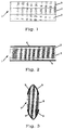
Ausführungsbeispiele der Erfindung werden nachfolgend anhand der Patentzeichnung näher erläutert. In der Zeichnung zeigen im einzelnen
- Figur 1:
- in schematischer Darstellung einen Längsschnitt durch ein erfindungsgemäßes Bauteil in Form einer Faser in einer ersten Ausführungsform,
- Figur 2:
- in schematischer Darstellung einen Längsschnitt durch ein erfindungsgemäßes Bauteil in Form einer Faser in einer zweiten Ausführungsform,
- Figur 3:
- in schematischer Darstellung einen Längsschnitt durch eine optische Linse,
- Figur 4:
- in schematischer Darstellung einen Längsschnitt durch einen Lichtleitstab,
- Figur 5:
- einen radialen Querschnitt durch ein erfindungsgemäßes Bauteil in Form eines Lichtleitstabes in einer zweiten Ausführungsform und
- Figur 6:
- ein Zeitstanddiagramm, das das Lebensdauerverhalten erfindungsgemäßer optischer Bauteile bei Bestrahlung mit UV-Strahlung wiedergibt.
- Figure 1:
- a schematic representation of a longitudinal section through an inventive component in the form of a fiber in a first embodiment,
- Figure 2:
- a schematic representation of a longitudinal section through an inventive component in the form of a fiber in a second embodiment,
- Figure 3:
- a schematic representation of a longitudinal section through an optical lens,
- Figure 4:
- a schematic representation of a longitudinal section through a light guide rod,
- Figure 5:
- a radial cross section through a component according to the invention in the form of a light guide rod in a second embodiment and
- Figure 6:
- a timing diagram that shows the life behavior of optical components according to the invention when irradiated with UV radiation.
Bei der in Figur 1 dargestellten Ausführungsform ist das optische Bauteil in Form einer optischen Faser ausgebildet, der insgesamt die Bezugsziffer 1 zugeordnet ist. Die Faser 1 besteht aus einem Kern 2 aus undotiertem, synthetisch hergestelltem Quarzglas. Der Kern 2 ist umhüllt von einem Mantel 3. Der Mantel 3 besteht aus synthetischem Quarzglas, das mit ca. 4 Gew.-% Fluor dotiert ist. Die Faser 1 hat eine Länge von 1m. Der Durchmesser des Kerns 2 der Faser 1 beträgt ca. 200 µm. Der Mantel 3 weist eine Dicke von 100 µm auf. Der Gesamtaußendurchmesser der Faser 1 beträgt somit 400 µm; das Verhältnis der Mantelstärke zum Gesamtaußendurchmesser beträgt 1:4.In the embodiment shown in FIG. 1 , the optical component is in the form of an optical fiber, to which
Der Kern 2 ist mit Wasserstoff in einer Konzentration von 5 x 10²⁰ Moleküle/cm3 beladen und weist einen Hydroxylionen-Gehalt von ca. 2 ppm auf.The
Die Beladung der Faser 1 mit Wasserstoff erfolgte bei einer Temperatur von 80 °C und einem Druck von etwa 30 MPa (300 atm) in wasserstoffhaltiger Atmosphäre. Die Beladungsdauer betrug 200 Stunden.The loading of the
Die Faser 1 zeichnet sich durch einen großen Kernquerschnitt aus und wird für eine Anwendung im Bereich der Leistungsübertragung energiereicher UV-Strahlung für industrielle Anwendungen, beispielsweise für die Übertragung von Excimerlaserlicht bei Stepper-Maschinen eingesetzt. Hierbei dürfen an die Biegsamkeit der Faser keine hohen Ansprüche gestellt werden. Zur Verhinderung der Ausdiffusion des Wasserstoffes wird hierzu die Faser in einer (in der Figur 1 nicht dargestellten) Hülse geführt, die mittels Peltier-Elementen kühlbar ist. Die übertragene UV-Strahlung hat eine Wellenlänge von 193 nm und eine Energiedichte von ca. 2 J/cm2.The
Sofern in den nachfolgenden Figuren 2 bis 6 identische Bezugsziffern wie in Figur 1 verwendet werden, sollen diese gleiche oder äquivalente Bauteile bezeichnen, wie sie anhand Figur 1 für die jeweiligen Bezugsziffern erläutert sind.Insofar as identical reference numerals as in FIG. 1 are used in the following FIGS. 2 to 6, these are to denote the same or equivalent components as are explained with reference to FIG. 1 for the respective reference numerals.
Bei dem Ausführungsbeispiel gemäß Figur 2 ist das erfindungsgemäße Bauteil ebenfalls in Form einer optischen Faser 1 ausgebildet. Es weist einen Kern 2 aus Quarzglas, das mit ca. 1 Gew.-% Fluor dotiert ist und einen Mantel 3 aus mit ca. 5 Gew.-% Fluor dotiertem Quarzglas auf. Der Mantel 3 ist umhüllt von einer 0,5 µm dicken Diffusionssperrschicht 4 aus Graphit. Die Faser 1 hat eine Länge von ca. 0,5 m. Der Durchmesser des Kerns 2 der Faser 1 beträgt ca. 50 µm. Der Mantel 3 weist eine Dicke von 2,5 µm auf. Der Gesamtaußendurchmesser der Faser 1 beträgt somit 56 µm.In the exemplary embodiment according to FIG. 2 , the component according to the invention is also designed in the form of an
Der Kern 2 ist mit Deuterium in einer Konzentration von 5 x 10²⁰ Molekülen/cm3 beladen und weist einen Hydroxylionen-Gehalt von ca. 600 ppm auf.The
Die Beladung der Faser 1 mit Deuterium erfolgte bei einer Temperatur von 80 °C und einem Druck von etwa 37 MPa (370 atm) in deuteriumhaltiger Atmosphäre. Die Beladungsdauer betrug 200 Stunden.The
Die Faser 1 ist zur Anwendung in einem Dentalgerät zur Bestrahlung von Zähnen mit UV-Strahlung einer Wellenlänge von 193 nm bestimmt. Hierzu werden einer Vielzahl der Fasern 1 zu einem Lichtleitbündel zusammengefaßt.The
Zur Behandlung von Zähnen wird eine von einem Excimerlaser ausgehende UV-Strahlung einer Wellenlänge von 193 nm und einer Energiedichte von 2 J/cm2 übertragen, wobei die Impulslänge der Laserimpulse auf 20 ns und die Repetitionsrate auf 25 Hz eingestellt ist. Dabei konnte auch nach längerer Betriebsdauer, die ca. 2000 Laserimpulsen entspricht, keine Abnahme der anfänglichen Transmission des Quarzglases festgestellt werden. Der Mantel 3 und die Diffusionssperrschicht 4 verhindern die Ausdiffusion von Deuterium und erlauben einen Einsatz der Faser 1 auch bei höheren Temperaturen, beispielsweise um 80 °C.To treat teeth, UV radiation from an excimer laser with a wavelength of 193 nm and an energy density of 2 J / cm 2 is transmitted, the pulse length of the laser pulses being set to 20 ns and the repetition rate to 25 Hz. Even after a long period of operation, which corresponds to approx. 2000 laser pulses, no decrease in the initial transmission of the quartz glass was found. The
Die Faser ist auch zum Einsatz im Bereich der Angioplastie geeignet. Hierbei wird üblicherweise mit UV-Strahlung einer Wellenlänge von 308 nm gearbeitet. Zur Herstellung eines Katheters werden mehrere der in Figur 2 dargestellten Fasern zu einem Faserbündel zusammengefaßt. Es wird eine UV-Strahlung einer Wellenlänge von 308 nm mit einer Energiedichte von 4 J/cm2 übertragen. Hierfür wird ein KrF-Excimerlaser eingesetzt, bei dem die Impulslänge der Laserimpulse auf 20 ns und die Repetitionsrate auf 20 Hz eingestellt ist. Die Betriebstemperatur während der Übertragung beträgt ca. 37 °C, die Übertragungsdauer 24 Stunden. Unter diesen Bedingungen wurde bei einer Wellenlänge von 308 nm keine durch die UV-Strahlung erzeugte irreversible Zusatzdämfung des Quarzglases festgestellt.The fiber is also suitable for use in the field of angioplasty. Usually UV radiation with a wavelength of 308 nm is used. To produce a catheter, several of the fibers shown in FIG. 2 are combined to form a fiber bundle. UV radiation with a wavelength of 308 nm and an energy density of 4 J / cm 2 is transmitted. A KrF excimer laser is used for this, in which the pulse length of the laser pulses is set to 20 ns and the repetition rate to 20 Hz. The operating temperature during the transfer is approx. 37 ° C, the transfer time is 24 hours. Under these conditions, no irreversible additional attenuation of the quartz glass produced by the UV radiation was found at a wavelength of 308 nm.
Die erfindungsgemäße Verwendung eines optischen Bauteils wird nachfolgend anhand der Figuren 3 und 4 erläutert. In Figur 3 ist eine optische Linse 7 aus Quarzglas in einem Querschnitt dargestellt. Die Lichtaustrittsfläche 8 der Linse 7 ist an ihrem äußeren Rand mit einer umlaufenden, geschlossenen Metallschicht 9 aus Aluminium versehen. Diese Metallschicht 9, die nach dem Beladen der Linse 7 durch Kathodenzerstäubung aufgesputtert worden ist, behindert die Ausdiffusion von Wasserstoff aus der Linse 7. Das Quarzglas der Linse 7 ist mit etwa 7,5 x 10²¹ Molekülen/cm3 Wasserstoff beladen.The use of an optical component according to the invention is explained below with reference to FIGS. 3 and 4. In Figure 3 , an optical lens 7 made of quartz glass is shown in a cross section. The
Die Linse 7 wurde mit einer Excimerlaser-Strahlung der Wellenlänge 265 nm, einer Energiedichte von 3,5 J/cm2, mit einer Impulslänge der Laserimpulse von 20 ns und mit einer Repetitionsrate von 20 Hz, 24 Stunden lang bei Raumtemperatur bestrahlt. Danach wurde bei einer Meßwellenlänge von 248 nm eine durch die UV-Strahlung erzeugte irreversible Zusatzdämfung des Quarzglases von lediglich 0,2 dB/m festgestellt.The lens 7 was irradiated with excimer laser radiation having a wavelength of 265 nm, an energy density of 3.5 J / cm 2 , a pulse length of the laser pulses of 20 ns and a repetition rate of 20 Hz for 24 hours at room temperature. Then at one Measurement wavelength of 248 nm an irreversible additional attenuation of the quartz glass produced by the UV radiation of only 0.2 dB / m was found.
Figur 4 zeigt ausschnittsweise einen Längsschnitt durch einen Lichtleitstab 10. Dieser weist einen Lichtleiter 11 auf, der aus einer Vielzahl einzelner Quarzglas-Lichtleitfasern gebildet ist. Sein Außendurchmesser beträgt 1 mm. Der Lichtleiter 11, der eine Wasserstoffkonzentration von 7,5 x 10²¹ Molekülen/cm3 aufweist, ist bereichsweise von einer Schutzhülle 12 umgeben, die aus einem aus der Dampfphase abgeschiedenen Siliziumoxinitrid besteht. Die Schutzhülle 12 läßt ringförmige Öffnungen 13 zum Lichtleiter 11 mit einer Breite von ca. 1 mm frei. Die Schutzhülle 12 weist eine Dicke von 2 µm auf und behindert die Ausdiffusion von Wasserstoff aus dem Lichtleiter 11. Die Schutzhülle 12 kann vor dem Beladen des Lichtleiters 11 mit Wasserstoff aufgebracht werden. Die Öffnungen 13 erlauben die Eindiffusion von Wasserstoff in den Lichtleiter 11. FIG. 4 shows a section of a longitudinal section through a
Bei dem in Figur 5 gezeigten Querschnitt durch einen dem in Figur 4 dargestellten ähnlichen Lichtleitstab 10, ist die Mantelfläche des Lichtleiters 11 vollständig von einer ersten, dünnen, geschlossenen Schutzschicht 14 und einer zweiten, dicken, geschlossenen Schutzschicht 15 umgeben. Die dünne Schutzschicht 14 weist eine Dicke von 0,5 µm, die dicke Schutzschicht 15 eine Dicke von 3 µm auf. Die Schutzschichten 14; 15, die aus Quarzglas bestehen, das einen kleineren Brechungsindex aufweist, als das Quarzglas des Lichtleiters 11, verhindern die Ausdiffusion von Wasserstoff aus dem Lichtleiter 11 und sie tragen gleichzeitig zur Lichtführung innerhalb des Lichtleiters bei.In the cross section shown in FIG. 5 through a
Das Beladen des Lichtleiters 11 mit Wasserstoff erfolgt derart, daß zunächst die dünne Schutzschicht 14 auf den Lichtleiter 11 aufgebracht wird. Diese schützt den Lichtleiter 11 vor mechanischen Beschädigungen. Danach wird der Lichtleiter 11, wie oben beschrieben, mit Wasserstoff beladen, und anschließend die dickere Schutzschicht 15 auf die dünne Schutzschicht 14 aufgebracht, die die Ausdiffusion von Wasserstoff verhindert.The
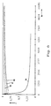
In Figur 6 ist ein Zeitstanddiagramm von erfindungsgemäßen optischen Fasern im Vergleich zu dem Zeitstanddiagramm einer üblichen optischen Faser dargestellt. Für die Messungen des Zeitstandverhaltens der Fasern wurden in diese UV-Strahlung eine Wellenlänge von 248 nm mittels eines KrF-Excimerlaser eingekoppelt. Die dabei eingestellte Energiedichte der Strahlung betrug 3,0 J/cm2, die Impulslänge der Laserstrahlung 15 ns und die Repetitionsrate 20 Hz. Die Faserlänge war jeweils 1 m. Die Geometrie der Fasern entspricht im übrigen derjenigen optischen Faser, wie sie anhand Figur 2 erläutert worden ist. Es wurde die Transmission der Fasern in Abhängigkeit von der Anzahl der Laserimpulse gemessen. In dem Diagramm gemäß Figur 6 ist auf der y-Achse eine auf die Anfangstransmission der Fasern normierte Transmission "T", und auf der x-Achse die Anzahl der Laserimpulse "N" aufgetragen. In dem Diagramm sind die Zeitstandkurven von insgesamt vier unterschiedlichen Fasern eingetragen, die sich lediglich in ihrer Deuteriumkonzentration im Kern unterscheiden. FIG. 6 shows a timing diagram of optical fibers according to the invention in comparison to the timing diagram of a conventional optical fiber. To measure the creep behavior of the fibers, a wavelength of 248 nm was coupled into this UV radiation using a KrF excimer laser. The energy density of the radiation set was 3.0 J / cm 2 , the pulse length of the laser radiation was 15 ns and the repetition rate was 20 Hz. The fiber length was 1 m in each case. The geometry of the fibers otherwise corresponds to that of the optical fiber, as has been explained with reference to FIG. 2. The transmission of the fibers was measured as a function of the number of laser pulses. In the diagram 6, a transmission "T" normalized to the initial transmission of the fibers is plotted on the y-axis, and the number of laser pulses "N" is plotted on the x-axis. The diagram shows the creep curves of a total of four different fibers, which differ only in their deuterium concentration in the core.
Die mit der Bezugsziffer 16 bezeichnete Kurve repräsentiert das Zeitstandverhalten einer Faser mit 5 x 10¹⁹ Molekülen/cm3, die Bezugsziffer 17 einer Faser mit 1 x 10²⁰ Molekülen/cm3 und die Bezugsziffer 18 einer Faser mit 5 x 10²⁰ Moleküle/cm3 Deuterium im Kern.The curve designated by the
Das Zeitstanddiagramm zeigt deutlich, daß eine Photodegradation bei den erfindungsgemäßen Fasern 16,17,18 nicht auftritt.The creep diagram clearly shows that photodegradation does not occur in the
Demgegenüber zeigt die handelsübliche optische Faser mit einem mit 5 x 10¹⁸ Molekülen/cm3 Deuterium beladenen Kernglas, deren Zeitstandverhalten durch die Kurve 19 repräsentiert wird, bereits nach ca. 1000 Laserimpulsen eine deutliche, irreversible Abnahme der Transmission.In contrast, the commercially available optical fiber with a core glass loaded with 5 x 10 18 molecules / cm 3 deuterium, the creep behavior of which is represented by
Das erfindungsgemäße Bauteil ist zur Übertragung von Excimerlaser-Strahlung im medizinischen Bereich, beispielsweise in der Angioplastie, in der Augenheilkunde zur Ablation von Hornhautgewebe oder für die Behandlung von Zähnen geeignet. Weiterhin kommen industrielle Anwendungen der erfindungsgemäßen Bauteile, beispielsweise zur Übertragung von Excimerlaserlicht in Steppermaschinen oder zur Materialbehandlung, sowie in der Spektroskopie zur Übertragung von Deuteriumlampenlicht bei der Kapillarelektrophorese in Frage.The component according to the invention is suitable for the transmission of excimer laser radiation in the medical field, for example in angioplasty, in ophthalmology for the ablation of corneal tissue or for the treatment of teeth. Furthermore, industrial applications of the components according to the invention are possible, for example for the transmission of excimer laser light in stepper machines or for material treatment, and in spectroscopy for the transmission of deuterium lamp light in capillary electrophoresis.
Claims (16)
Applications Claiming Priority (4)
| Application Number | Priority Date | Filing Date | Title |
|---|---|---|---|
| DE19547904A DE19547904A1 (en) | 1995-12-21 | 1995-12-21 | Optical component for transmitting UV radiation |
| DE19547904 | 1995-12-21 | ||
| JP12862596A JP3719776B2 (en) | 1996-05-23 | 1996-05-23 | Optical fiber for ultraviolet transmission, manufacturing method thereof, and transmission line using the same |
| JP128625/96 | 1996-05-23 |
Publications (1)
| Publication Number | Publication Date |
|---|---|
| EP0780707A1 true EP0780707A1 (en) | 1997-06-25 |
Family
ID=26021512
Family Applications (1)
| Application Number | Title | Priority Date | Filing Date |
|---|---|---|---|
| EP96120168A Withdrawn EP0780707A1 (en) | 1995-12-21 | 1996-12-18 | Element for UV high energy radiation transmission and method of fabrication of such an element and its utilisation |
Country Status (2)
| Country | Link |
|---|---|
| US (1) | US6220059B1 (en) |
| EP (1) | EP0780707A1 (en) |
Cited By (4)
| Publication number | Priority date | Publication date | Assignee | Title |
|---|---|---|---|---|
| WO2008140676A2 (en) * | 2007-05-09 | 2008-11-20 | Corning Incorporated | Glasses having low oh, od levels |
| US9746749B2 (en) | 2008-07-11 | 2017-08-29 | Nkt Photonics A/S | Lifetime extending and performance improvements of optical fibers via loading |
| EP1849029B1 (en) | 2005-02-04 | 2018-06-20 | Centre National de la Recherche Scientifique (CNRS) | Composite optical fibre for a laser- and pump-wave confinement laser and use thereof in lasers |
| US10228510B2 (en) | 2014-12-18 | 2019-03-12 | Nkt Photonics A/S | Photonic crystal fiber, a method of production thereof and a supercontinuum light source |
Families Citing this family (20)
| Publication number | Priority date | Publication date | Assignee | Title |
|---|---|---|---|---|
| US6763686B2 (en) * | 1996-10-23 | 2004-07-20 | 3M Innovative Properties Company | Method for selective photosensitization of optical fiber |
| DE59810104D1 (en) | 1997-09-22 | 2003-12-11 | Infineon Technologies Ag | OPTICAL SYSTEM FOR COUPLING LASER RADIATION INTO A LIGHTWAVE GUIDE AND METHOD FOR THE PRODUCTION THEREOF |
| US6944380B1 (en) | 2001-01-16 | 2005-09-13 | Japan Science And Technology Agency | Optical fiber for transmitting ultraviolet ray, optical fiber probe, and method of manufacturing the optical fiber probe |
| US6892012B2 (en) * | 2001-05-18 | 2005-05-10 | Fujikura, Ltd. | Optical fiber bundle unit for transmitting ultraviolet light |
| US6856713B2 (en) * | 2001-08-20 | 2005-02-15 | Polymicro Technologies, Llc | Optical component and method of making the same |
| US6857293B2 (en) * | 2001-12-20 | 2005-02-22 | 3M Innovative Properties Company | Apparatus for selective photosensitization of optical fiber |
| WO2003091774A1 (en) * | 2002-04-26 | 2003-11-06 | Japan Science And Technology Corporation | Fiber grating and method for making the same |
| US6865322B2 (en) * | 2002-06-04 | 2005-03-08 | Goi Acquisitions Llc | Fiber optic device with enhanced resistance to environmental conditions and method |
| US6741774B2 (en) * | 2002-06-04 | 2004-05-25 | Gould Fiber Optics, Inc. | Fiber optic device with enhanced resistance to environmental conditions and method |
| EP1422202A1 (en) * | 2002-11-25 | 2004-05-26 | Alcatel | Method of fabricating an optical fiber |
| US20050252246A1 (en) * | 2004-05-12 | 2005-11-17 | Shirley Arthur I | Method for manufacturing optical fiber |
| US6907170B1 (en) | 2004-07-22 | 2005-06-14 | Halliburton Energy Services, Inc. | Hydrogen diffusion delay barrier for fiber optic cables used in hostile environments |
| US7218820B2 (en) * | 2004-07-22 | 2007-05-15 | Welldynamics, Inc. | Method and system for providing a hydrogen diffusion barrier for fiber optic cables used in hostile environments |
| US7400803B2 (en) | 2005-03-25 | 2008-07-15 | Welldynamics, B.V. | Method and apparatus for providing a hydrogen diffusion barrier for fiber optic cables used in hostile environments |
| US7024089B2 (en) | 2004-07-26 | 2006-04-04 | Sbc Knowledge Ventures, L.P. | Fiber distribution frame arrangement having a centralized controller which universally controls and monitors access to fiber distribution frames |
| US20070105703A1 (en) * | 2005-11-07 | 2007-05-10 | Bookbinder Dana C | Deuteroxyle-doped silica glass, optical member and lithographic system comprising same and method of making same |
| US7635658B2 (en) * | 2005-11-07 | 2009-12-22 | Corning Inc | Deuteroxyl-doped silica glass, optical member and lithographic system comprising same and method of making same |
| US7934390B2 (en) * | 2006-05-17 | 2011-05-03 | Carl Zeiss Smt Gmbh | Method for manufacturing a lens of synthetic quartz glass with increased H2 content |
| FR2943337B1 (en) * | 2009-03-20 | 2011-12-23 | Draka Comteq France | METHOD FOR PROCESSING OPTICAL FIBERS WITH DEUTERIUM |
| DE102019115928B4 (en) * | 2019-06-12 | 2023-07-27 | J-Fiber Gmbh | Hydrogen barrier quartz fiber and method of making same |
Citations (6)
| Publication number | Priority date | Publication date | Assignee | Title |
|---|---|---|---|---|
| JPS59121007A (en) * | 1982-12-28 | 1984-07-12 | Toshiba Corp | Optical fiber device for infrared laser treating device |
| EP0286190A2 (en) * | 1987-04-09 | 1988-10-12 | Philips Patentverwaltung GmbH | Connection end of a light-guide glued on a mount |
| EP0401845A2 (en) | 1989-06-09 | 1990-12-12 | Heraeus Quarzglas GmbH | Optical members and blanks of synthetic silica glass and method for their production |
| EP0483477A1 (en) * | 1990-10-26 | 1992-05-06 | Heraeus Quarzglas GmbH | Flexible optical device for the transmission of light and use of the device |
| EP0529268A2 (en) * | 1991-08-28 | 1993-03-03 | Leybold Aktiengesellschaft | Anti-reflex hard coating for plastic lenses |
| JPH0656457A (en) | 1992-08-12 | 1994-03-01 | Fujikura Ltd | Production of fiber for transmitting ultraviolet light |
Family Cites Families (3)
| Publication number | Priority date | Publication date | Assignee | Title |
|---|---|---|---|---|
| JPS6075802A (en) * | 1983-10-03 | 1985-04-30 | Sumitomo Electric Ind Ltd | Production of image fiber |
| GB8912470D0 (en) * | 1989-05-31 | 1989-07-19 | Stc Plc | Carbon coating of optical fibres |
| US5478371A (en) * | 1992-05-05 | 1995-12-26 | At&T Corp. | Method for producing photoinduced bragg gratings by irradiating a hydrogenated glass body in a heated state |
-
1996
- 1996-12-18 EP EP96120168A patent/EP0780707A1/en not_active Withdrawn
- 1996-12-23 US US08/772,659 patent/US6220059B1/en not_active Expired - Lifetime
Patent Citations (7)
| Publication number | Priority date | Publication date | Assignee | Title |
|---|---|---|---|---|
| JPS59121007A (en) * | 1982-12-28 | 1984-07-12 | Toshiba Corp | Optical fiber device for infrared laser treating device |
| EP0286190A2 (en) * | 1987-04-09 | 1988-10-12 | Philips Patentverwaltung GmbH | Connection end of a light-guide glued on a mount |
| EP0401845A2 (en) | 1989-06-09 | 1990-12-12 | Heraeus Quarzglas GmbH | Optical members and blanks of synthetic silica glass and method for their production |
| EP0483477A1 (en) * | 1990-10-26 | 1992-05-06 | Heraeus Quarzglas GmbH | Flexible optical device for the transmission of light and use of the device |
| DE4034059C1 (en) | 1990-10-26 | 1992-05-14 | Heraeus Quarzglas Gmbh, 6450 Hanau, De | |
| EP0529268A2 (en) * | 1991-08-28 | 1993-03-03 | Leybold Aktiengesellschaft | Anti-reflex hard coating for plastic lenses |
| JPH0656457A (en) | 1992-08-12 | 1994-03-01 | Fujikura Ltd | Production of fiber for transmitting ultraviolet light |
Non-Patent Citations (2)
| Title |
|---|
| PATENT ABSTRACTS OF JAPAN vol. 18, no. 288 (C - 1207) 2 June 1994 (1994-06-02) * |
| PATENT ABSTRACTS OF JAPAN vol. 8, no. 248 (P - 313)<1685> 14 November 1984 (1984-11-14) * |
Cited By (15)
| Publication number | Priority date | Publication date | Assignee | Title |
|---|---|---|---|---|
| EP1849029B1 (en) | 2005-02-04 | 2018-06-20 | Centre National de la Recherche Scientifique (CNRS) | Composite optical fibre for a laser- and pump-wave confinement laser and use thereof in lasers |
| WO2008140676A3 (en) * | 2007-05-09 | 2009-01-08 | Corning Inc | Glasses having low oh, od levels |
| CN101730667B (en) * | 2007-05-09 | 2013-03-27 | 康宁股份有限公司 | Glasses having low oh, od levels |
| WO2008140676A2 (en) * | 2007-05-09 | 2008-11-20 | Corning Incorporated | Glasses having low oh, od levels |
| US9746749B2 (en) | 2008-07-11 | 2017-08-29 | Nkt Photonics A/S | Lifetime extending and performance improvements of optical fibers via loading |
| US9971230B2 (en) | 2008-07-11 | 2018-05-15 | Nkt Photonics A/S | Lifetime extending and performance improvements of optical fibers via loading |
| US9766530B2 (en) | 2008-07-11 | 2017-09-19 | Nkt Photonics A/S | Supercontinuum light source |
| US10281797B2 (en) | 2008-07-11 | 2019-05-07 | Nkt Photonics A/S | Lifetime extending and performance improvements of optical fibers via loading |
| US10474003B2 (en) | 2008-07-11 | 2019-11-12 | Nkt Photonics A/S | Lifetime extending and performance improvements of optical fibers via loading |
| US11048145B2 (en) | 2008-07-11 | 2021-06-29 | Nkt Photonics A/S | Lifetime extending and performance improvements of optical fibers via loading |
| US10228510B2 (en) | 2014-12-18 | 2019-03-12 | Nkt Photonics A/S | Photonic crystal fiber, a method of production thereof and a supercontinuum light source |
| US10557987B2 (en) | 2014-12-18 | 2020-02-11 | Nkt Photonics A/S | Photonic crystal fiber, a method of production thereof and a supercontinuum light source |
| US10928584B2 (en) | 2014-12-18 | 2021-02-23 | Nkt Photonics A/S | Photonic crystal fiber, a method of production thereof and a supercontinuum light source |
| US11409033B2 (en) | 2014-12-18 | 2022-08-09 | Nkt Photonics A/S | Photonic crystal fiber, a method of production thereof and a supercontinuum light source |
| US11719881B2 (en) | 2014-12-18 | 2023-08-08 | Nkt Photonics A/S | Photonic crystal fiber, a method of production thereof and a supercontinuum light source |
Also Published As
| Publication number | Publication date |
|---|---|
| US6220059B1 (en) | 2001-04-24 |
Similar Documents
| Publication | Publication Date | Title |
|---|---|---|
| EP0780707A1 (en) | Element for UV high energy radiation transmission and method of fabrication of such an element and its utilisation | |
| DE2906071C2 (en) | Method of drawing a fiber of thermoplastic material to make optical waveguides | |
| DE102005017752B4 (en) | Quartz glass optical component, method of making the component and use thereof | |
| EP1982963B1 (en) | Method for producing an optical component of synthetic quartz glass with enhanced radiation resistance, and blank for producing the component | |
| DE102009055326A1 (en) | High purity quartz glass with low absolute refractive index | |
| DE19505929C1 (en) | Low attenuation optical component e.g.. fibre or preform | |
| DE112004000579T5 (en) | Optical elements and methods for producing optical elements | |
| EP1770417A1 (en) | Optical fibre and manufacturing method thereof | |
| DE10316487B4 (en) | Process for producing a preform for optical fibers | |
| DE19942443A1 (en) | UV transparent optical glass material, especially for VUV excimer radiation applications, is produced from a high purity silicon compound by a soot process and is free from impurities apart from hydroxyl groups | |
| EP0964832B1 (en) | Synthetic quartz glass preform and device for the production thereof | |
| DE4034059C1 (en) | ||
| DE3150525A1 (en) | POLYCRYSTALLINE ZINKSULFID AND ZINKSELENID PRODUCTS WITH IMPROVED OPTICAL QUALITY AND METHOD FOR THE PRODUCTION OF SUCH ARTICLES | |
| DE19928971A1 (en) | Multi-cladding optical fibers with long-period gratings, e.g. for fiber amplifiers | |
| DE19547904A1 (en) | Optical component for transmitting UV radiation | |
| DE4206182C2 (en) | Component for the transmission of high-energy light and use of the component | |
| DE102008049325B4 (en) | Method for producing a tubular semifinished product made of quartz glass and semi-finished products made of quartz glass | |
| DE102004018887B4 (en) | A method of manufacturing a quartz glass component for use with a source of ultraviolet rays and a method of aptitude diagnosis of such a quartz glass component | |
| WO2000015570A1 (en) | Optical component made of silica glass and method for the production thereof | |
| EP4030204B1 (en) | Microstructured optical fibre and preform for same | |
| DE102019115928B4 (en) | Hydrogen barrier quartz fiber and method of making same | |
| DE3803413C1 (en) | ||
| DE4404874C2 (en) | Method for increasing the light sensitivity of a doped optical waveguide | |
| DE4209004A1 (en) | Light waveguide preform prodn - by forming complex former and rare earth cpd. using heat and leading into substrate tube | |
| DE3133013A1 (en) | "METHOD FOR PRODUCING A LIGHT-FIBER FIBER BLANK" |
Legal Events
| Date | Code | Title | Description |
|---|---|---|---|
| PUAI | Public reference made under article 153(3) epc to a published international application that has entered the european phase |
Free format text: ORIGINAL CODE: 0009012 |
|
| 17P | Request for examination filed |
Effective date: 19961220 |
|
| AK | Designated contracting states |
Kind code of ref document: A1 Designated state(s): DE FR GB |
|
| 17Q | First examination report despatched |
Effective date: 20011115 |
|
| RAP1 | Party data changed (applicant data changed or rights of an application transferred) |
Owner name: HERAEUS QUARZGLAS GMBH & CO. KG |
|
| STAA | Information on the status of an ep patent application or granted ep patent |
Free format text: STATUS: THE APPLICATION IS DEEMED TO BE WITHDRAWN |
|
| 18D | Application deemed to be withdrawn |
Effective date: 20020528 |