EP0778566B1 - Apparatus and method for synthesising an information signal and a reproduction control signal and information signal recording apparatus - Google Patents
Apparatus and method for synthesising an information signal and a reproduction control signal and information signal recording apparatus Download PDFInfo
- Publication number
- EP0778566B1 EP0778566B1 EP96308568A EP96308568A EP0778566B1 EP 0778566 B1 EP0778566 B1 EP 0778566B1 EP 96308568 A EP96308568 A EP 96308568A EP 96308568 A EP96308568 A EP 96308568A EP 0778566 B1 EP0778566 B1 EP 0778566B1
- Authority
- EP
- European Patent Office
- Prior art keywords
- information
- sub
- code
- signal
- synthesis signal
- Prior art date
- Legal status (The legal status is an assumption and is not a legal conclusion. Google has not performed a legal analysis and makes no representation as to the accuracy of the status listed.)
- Expired - Lifetime
Links
Images


Classifications
-
- G—PHYSICS
- G11—INFORMATION STORAGE
- G11B—INFORMATION STORAGE BASED ON RELATIVE MOVEMENT BETWEEN RECORD CARRIER AND TRANSDUCER
- G11B20/00—Signal processing not specific to the method of recording or reproducing; Circuits therefor
- G11B20/10—Digital recording or reproducing
-
- G—PHYSICS
- G11—INFORMATION STORAGE
- G11B—INFORMATION STORAGE BASED ON RELATIVE MOVEMENT BETWEEN RECORD CARRIER AND TRANSDUCER
- G11B20/00—Signal processing not specific to the method of recording or reproducing; Circuits therefor
- G11B20/00086—Circuits for prevention of unauthorised reproduction or copying, e.g. piracy
- G11B20/00884—Circuits for prevention of unauthorised reproduction or copying, e.g. piracy involving a watermark, i.e. a barely perceptible transformation of the original data which can nevertheless be recognised by an algorithm
- G11B20/00913—Circuits for prevention of unauthorised reproduction or copying, e.g. piracy involving a watermark, i.e. a barely perceptible transformation of the original data which can nevertheless be recognised by an algorithm based on a spread spectrum technique
-
- G—PHYSICS
- G11—INFORMATION STORAGE
- G11B—INFORMATION STORAGE BASED ON RELATIVE MOVEMENT BETWEEN RECORD CARRIER AND TRANSDUCER
- G11B20/00—Signal processing not specific to the method of recording or reproducing; Circuits therefor
- G11B20/00086—Circuits for prevention of unauthorised reproduction or copying, e.g. piracy
-
- G—PHYSICS
- G11—INFORMATION STORAGE
- G11B—INFORMATION STORAGE BASED ON RELATIVE MOVEMENT BETWEEN RECORD CARRIER AND TRANSDUCER
- G11B20/00—Signal processing not specific to the method of recording or reproducing; Circuits therefor
- G11B20/10—Digital recording or reproducing
- G11B20/10527—Audio or video recording; Data buffering arrangements
-
- H—ELECTRICITY
- H04—ELECTRIC COMMUNICATION TECHNIQUE
- H04N—PICTORIAL COMMUNICATION, e.g. TELEVISION
- H04N5/00—Details of television systems
- H04N5/76—Television signal recording
- H04N5/91—Television signal processing therefor
- H04N5/913—Television signal processing therefor for scrambling ; for copy protection
- H04N2005/91307—Television signal processing therefor for scrambling ; for copy protection by adding a copy protection signal to the video signal
- H04N2005/91314—Television signal processing therefor for scrambling ; for copy protection by adding a copy protection signal to the video signal the copy protection signal being a pulse signal inserted in blanking intervals of the video signal, e.g. pseudo-AGC pulses, pseudo-sync pulses
-
- H—ELECTRICITY
- H04—ELECTRIC COMMUNICATION TECHNIQUE
- H04N—PICTORIAL COMMUNICATION, e.g. TELEVISION
- H04N5/00—Details of television systems
- H04N5/76—Television signal recording
- H04N5/91—Television signal processing therefor
- H04N5/913—Television signal processing therefor for scrambling ; for copy protection
- H04N2005/91307—Television signal processing therefor for scrambling ; for copy protection by adding a copy protection signal to the video signal
- H04N2005/91321—Television signal processing therefor for scrambling ; for copy protection by adding a copy protection signal to the video signal the copy protection signal being a copy protection control signal, e.g. a record inhibit signal
-
- H—ELECTRICITY
- H04—ELECTRIC COMMUNICATION TECHNIQUE
- H04N—PICTORIAL COMMUNICATION, e.g. TELEVISION
- H04N5/00—Details of television systems
- H04N5/76—Television signal recording
- H04N5/91—Television signal processing therefor
- H04N5/913—Television signal processing therefor for scrambling ; for copy protection
- H04N2005/91307—Television signal processing therefor for scrambling ; for copy protection by adding a copy protection signal to the video signal
- H04N2005/91328—Television signal processing therefor for scrambling ; for copy protection by adding a copy protection signal to the video signal the copy protection signal being a copy management signal, e.g. a copy generation management signal [CGMS]
-
- H—ELECTRICITY
- H04—ELECTRIC COMMUNICATION TECHNIQUE
- H04N—PICTORIAL COMMUNICATION, e.g. TELEVISION
- H04N5/00—Details of television systems
- H04N5/76—Television signal recording
- H04N5/91—Television signal processing therefor
- H04N5/913—Television signal processing therefor for scrambling ; for copy protection
- H04N2005/91307—Television signal processing therefor for scrambling ; for copy protection by adding a copy protection signal to the video signal
- H04N2005/9135—Television signal processing therefor for scrambling ; for copy protection by adding a copy protection signal to the video signal by superimposing the spectrally spread copy protection signal onto the video signal
-
- H—ELECTRICITY
- H04—ELECTRIC COMMUNICATION TECHNIQUE
- H04N—PICTORIAL COMMUNICATION, e.g. TELEVISION
- H04N5/00—Details of television systems
- H04N5/76—Television signal recording
- H04N5/91—Television signal processing therefor
- H04N5/913—Television signal processing therefor for scrambling ; for copy protection
- H04N2005/91357—Television signal processing therefor for scrambling ; for copy protection by modifying the video signal
- H04N2005/91371—Television signal processing therefor for scrambling ; for copy protection by modifying the video signal the video color burst signal being modified
Definitions
- the present invention relates to information signal copying system and method. More particularly, the invention relates to a copy prevention system in which a signal is not lost even in a communication by an analog signal.
- Fig. 1 is a diagram showing the principle of the copy prevention system.
- reference numeral 100 denotes a reproducing apparatus; 101 a recording medium for reproduction; 102 a reproducing unit; 110 a recording apparatus; 111 a recording unit; 112 a copy control signal detecting unit; 113 a recording medium for recording; 121 a read signal from the recording medium 101; 122 a reproduction signal which is supplied from the reproducing apparatus 100 to the recording apparatus 110; 123 a copy control signal; and 124 a write signal to the recording medium 113.
- a recording signal is read out from the recording medium 101 by the reproducing unit 102 and is outputted as a digital or analog reproduction signal 122.
- the copy control signal detecting unit 112 detects the copy control signal 123.
- the recording unit 111 generates the write signal 124 which inhibits or permits the recording to the recording medium 113 for recording.
- Fig. 2 is a block diagram of the recording apparatus by a digital signal.
- reference numeral 200 denotes an analog unit; 201 an information source from which information to be recorded is generated; and 210 a digital unit.
- the digital unit 210 comprises: an encoding unit 211, a copy prevention code generator 212, a synthesizer 213, a writing unit 214, and a recording medium 215.
- An analog information signal 231 is converted to a digital information signal 232 by an ADC (analog/digital converter) 221 and is supplied to the digital unit 210.
- ADC analog/digital converter
- the encoding unit 211 encodes the digital information signal and supplies an information code 233 to the synthesizer 213.
- the synthesizer 213 synthesizes the information code 233 and a copy prevention code 234 from the copy prevention code generator 212.
- An output signal 235 from the synthesizer 213 is supplied to the writing unit 214 and an output signal 236 of the writing unit 214 is recorded in the recording medium 215.
- the information code 233 and copy prevention code 234 are recorded in the recording medium 215.
- the system of Fig. 2 can be applied to, for example, a mastering of a read-only disk medium.
- Fig. 3 shows another example of a recording apparatus for digitally recording.
- the copy prevention code is added in the encoding unit 211.
- the information code 233 from the encoding unit 211 is supplied to a code reading unit 216 and an added copy prevention code 237 is separated.
- the copy prevention code is supplied to a control unit 217 of the copy prevention code.
- the control unit 217 limits a generation of copy. For example, when the copy prevention code is a code for permitting a copy of one generation, the control unit 217 generates a control signal 238 for rewriting the copy prevention code to a code for inhibiting the copy and a control signal 239 for instructing permission or inhibition of the recording of a signal to the recording medium 215 by the writing unit 214.
- the control signal 238 is supplied to a code changing unit 218, the copy prevention code is changed to a code having the contents of inhibiting the copy, and the writing is permitted by the control signal 239.
- the system of Fig. 3 can be applied to, for example, a digital VTR.
- Fig. 4 is a schematic diagram of a copy system by the digital connection.
- Reference numeral 301 denotes a digital data reproducing apparatus; 302 a digital data recording apparatus; and 311 a digital signal.
- the digital signal 311 is supplied from the digital data reproducing apparatus 301 to the digital data recording apparatus 302 and the recording operation of the digital data recording apparatus 302 is controlled by the copy control signal included in the digital signal 311.
- Fig. 5 shows an example of the copy system by the digital connection.
- reference numeral 400 denotes a reproducing apparatus; 401 a recording medium on the reproduction side; 402 a reading unit; 410 a digital interface; 411 a communication path; 420 a recording apparatus; 424 a copy prevention code reading unit; 425 a copy control signal control unit; 426 a code changing unit; 421 a writing unit; 423 a recording side recording medium; 431 a read signal; 432 a digital reproduction signal; 435 a copy prevention code which was read; 436 and 437 control signals; and 438 a write signal.
- the read signal 431 obtained from the recording medium 401 is supplied to the reading unit 402 and is outputted as a digital reproduction signal 432.
- the digital reproduction signal 432 passes through the communication path 411 of the digital interface 410 and is supplied to the code reading unit 424 and the copy prevention code 435 is separated.
- the copy control signal control unit 425 decodes the separated copy prevention code 433 and reads the information.
- the control signal 436 for changing the copy prevention code is outputted to the code changing unit 426 and the control signal 437 for instructing the permission or inhibition of the recording of the signal to the recording medium 425 is outputted to the writing unit 421.
- the permission and inhibition of the recording but also the limitation of the copy about the generation can be performed.
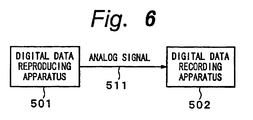
- Fig. 6 shows a schematic construction.
- Reference numeral 501 denotes a digital data reproducing apparatus; 502 a digital data recording apparatus; and 511 an analog signal transmitted between the apparatuses 501 and 502.
- the analog signal 511 which was D/A converted and outputted from the digital data reproducing apparatus 501 is inputted to the digital data recording apparatus 502 and is A/D converted and digitally recorded.
- the copy prevention control cannot be executed in the digital data recording apparatus 502.
- a few methods have been proposed as a method of preventing the copy by an analog interface.
- the analog signal is a video signal
- a phase of a color burst of an analog video signal to be outputted is partially inverted or a pseudo synchronization signal having an extremely large level is inserted as a sync signal for AGC, so that even if the normal reproduction can be performed.
- the video signal is recorded by the VTR, a normal reproduction image is not obtained in a monitor receiver.
- a digital copy prevention code is added to a signal in which an information source was digitally encoded.
- the digital recording apparatus detects the copy control signal and can execute the copy prevention control.
- the digital signal as a copy control signal added by the D/A conversion is dropped out.
- the copy control signal cannot be consequently detected in the digital recording apparatus in which the signal is finally recorded.
- the copy prevention control cannot be performed.
- it is necessary to prevent the copy by using the difference between the AGC methods of the VTR and the monitor receiver or the difference between the characteristics of the APC methods.
- the modified code signal can be combined with the audio signal to obtain a composite audio signal which is not readily distinguishable from the original audio signal by listening.
- the digital information can be recovered from the composite audio signal by a procedure which is essentially the compliment of that used to obtain the composite audio signal.
- EP-A-0,618,723 describes a system in which a video signal is processed to selectively permit copying by superposing in that portion of the video signal which does not contain useful picture information a copyright information signal indicative of whether the viewable picture that is displayed from the video signal is subject to copyright and a copy generation signal indicative of the number of successive generations of copies that can be made from the video signal.
- the copy control signal since a band of the additional information such as a copy control signal or the like is widened by the spread spectrum and the addition information is added to the signal band of the information source, the copy control signal cannot be deleted by a filter or the like. Since the spread spectrum signal is added, an influence by a deterioration or the like is hardly exerted on the original data. Further, as long as no synchronization is obtained at a timing when the spread spectrum is performed, it is difficult to perform not only the detection of the addition of the signal but also the detection of the copy control signal.
- different codes can be used as a PN code which is used for the spread spectrum and a several kinds of orthogonal codes can be also multiplied.
- the copy control signal is not erased even after the digital signal was D/A converted, the copy is prevented for the digital data recording apparatus which is connected in an analogwise manner. Since the copy control signal is not erased even in the signal recorded in the analog recording apparatus and the copy control signal cannot be deleted by a filter or the like, a very high effect of copy prevention can be obtained. Further, there is an advantage such that by multiplying the kind of spread spectrum and the orthogonal functions, an amount of information which can be added can be freely controlled.
- Fig. 7 is a diagram showing a construction of an embodiment of a recording apparatus according to the invention.
- an analog unit 800 has an information source 801 for generating an information signal to be recorded and a synthesizer 802 for synthesizing an information signal 831 and a copy control code 833.
- a synthesis signal 834 from the synthesizer 802 is converted into a digital signal by an ADC (analog/digital converter) 821.
- the digital signal is supplied to a digital unit 810.
- a copy control code generating unit 811 generates a copy control code 832 to control a copy prevention.
- the copy control code 832 is supplied to a spread spectrum unit 812 and is spread spectrum processed.
- the spread spectrum processed copy control code 833 is supplied to the synthesizer 802.
- a synthesis signal 835 which was converted into the digital signal is supplied to an encoding unit 813.
- the encoding unit 813 encodes digital information and its output 836 is supplied to a writing unit 814.
- a write signal 837 from the writing unit 814 is recorded into a recording medium 815.
- the analog unit 800 includes: a code reading unit 816 for extracting the spread spectrum processed copy control code multiplexed to the analog signal 831 from the information source 801; and a code changing unit 818 for changing the copy control code.
- the code changing unit 818 generates the synthesis signal 834 in which the copy control code which was spread spectrum processed was multiplexed to the analog information signal.
- the synthesis signal 834 is converted into the digital signal 835 by the ADC (analog/digital converter) 821.
- the digital signal 835 is supplied to the encoding unit 813 of the digital unit 810.
- An output signal of the ADC 821 is recorded into the recording medium 815 by the digital unit 810 in a manner similar to the foregoing embodiment.
- the information to be recorded there are audio information and/or video information.
- the recording medium 815 is a tape-shaped or disk-shaped medium in which a digital signal can be optically or magnetically recorded.
- a copy control code 838 extracted by the code reading unit 816 is supplied to a copy control signal control unit 817.
- the control unit 817 decodes the original copy control code and generates a copy control code 839 to be newly recorded.
- the copy control code 839 after the change is supplied to the code changing unit 818 and the copy control code in the synthesis signal 834 is changed.
- the new copy control code is also made identical to the original copy control code.
- the new copy control code is changed to a code indicative of the copy inhibition.
- the writing unit 814 When an original copy control signal 840 which is supplied from the copy control signal control unit 817 denotes the copy permission, the writing unit 814 records an output of the encoding unit 813 into the recording medium 815. When the signal 840 denotes the copy inhibition, the writing unit 814 doesn't record the output of the encoding unit 813 to the recording medium 815.
- the code reading unit 816 executes a process for an inverse spread spectrum and generates the copy control code 838 and also generates the synthesis signal and a control signal 841 for synchronization control to the code changing unit 818.
- the code changing unit 818 erases the original copy control code by the inverse spread spectrum and, subsequently, synthesizes the new copy control code 839 by the spread spectrum.
- the code changing unit 818 receives the control signal 841 which is used for the synchronization control that is executed for the inverse spread spectrum from the code reading unit 816.
- the copy control code is, for example, a code of two bits and is information to instruct a control about the copy as shown below.
- a reproducing apparatus 900 reproduces a recording medium 901 in which a synthesis signal has digitally been recorded.
- a read signal 931 outputted from the recording medium 901 for reproduction is set to a digital reproduction signal 932 by a reading unit 902 and is inputted to a decoding unit 903 and is decoded into a digital decoding signal 933 by the decoding unit 903. Further, the signal 933 is converted into an analog synthesis signal 934 by a DAC (digital/analog converter) 904.
- the analog synthesis signal 934 is supplied to an ADC 921 and an inverse spread spectrum unit 923 in a recording apparatus 920 through a communication path 911 of an analog interface 910. A copy control code which was spread spectrum processed has been added to the analog synthesis signal 934.
- a digital information signal 935 from the ADC 921 is encoded by an encoding unit 922.
- An encoding signal 936 from the encoding unit 922 is supplied to a writing unit 925.
- a write signal 939 from the writing unit 925 is recorded into a recording medium 926 for recording.
- a signal 937 which was inversely spread by the inverse spread spectrum unit 923 is inputted to a copy control code detecting unit 924 and a copy control code 938 is detected.
- the writing unit 925 is controlled by the copy control code 938. When the copy is permitted in accordance with the copy control code 938, the writing is performed. When the copy is inhibited, the writing is inhibited.
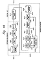
- Fig. 10 shows another embodiment of a copy system according to the invention.
- the reproducing apparatus 900 reproduces the recording medium 901, generates the analog synthesis signal 934 in which the analog information signal and the copy control code have been synthesized, and supplies the signal 934 to the recording apparatus 920 through the communication path 911 of the analog interface 910.
- the analog synthesis signal 934 is supplied to a code reading unit 927 of the recording apparatus 920 and a multiplexed copy control code 940 is extracted.
- a code changing unit 929 to change the copy control code is provided.
- the code changing unit 929 generates a synthesis signal 945 in which the spread spectrum processed copy control code has been multiplexed to the analog information signal.
- the synthesis signal 945 is converted into the digital signal 935 by the ADC 921.
- the digital signal is supplied to the encoding unit 922.
- the output signal of the ADC 921 is recorded into the recording medium 926 by the encoding unit 922.
- the copy control code 940 extracted by the code reading unit 927 is supplied to a copy control code control unit 928.
- the control unit 928 decodes the original copy control code 940 and generates a copy control code 941 to be newly recorded.
- the copy control code 941 after the change is supplied to the code changing unit 929 and the copy control code in the synthesis signal 945 is changed.
- the new copy control code is also made identical to the original copy control code.
- the original copy control code denotes the permission of the copy of one generation, the new copy control code is changed to the code indicative of the copy inhibition.
- the code reading unit 927 executes a process of the inverse spread spectrum, generates the copy control code 940, and also generates the synthesis signal and a control signal 943 which is used for synchronization control to the code changing unit 929.
- the code changing unit 929 erases the original control code by the inverse spread spectrum which was sync controlled by the control signal 943 and, subsequently, synthesizes the new copy control code 941 by the spread spectrum.
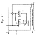
- Fig. 11 shows an example of the code reading unit 927 (similar to 816 as well).
- the synthesis signal 934 is supplied to a multiplier 11 and a sync control circuit 12.
- a PN (pseudo noise) code from a PN code generator 14 is supplied to the multiplier 11 and sync control circuit 12.
- the sync control circuit 12 extracts the timing signal 943 by using a fact that the PN code has a steep autocorrelation.
- An oscillating frequency and a phase of an oscillator 13 are controlled by the extracted timing signal 943 and an output signal of the oscillator 13 is supplied to the PN code generator 14.
- the PN code generated from the output of the oscillator 13 which was sync controlled and the synthesis signal 934 are multiplied by the multiplier 11, so that the demodulated copy control code 940 is derived from the multiplier 11.
- the copy control code 940 is supplied to the control unit 928.
- an M sequence maximum length sequence
- GOLD code or the like
- the former half sequence of its period and one bit on the lower significant side of the copy control code two bits
- the latter half sequence of the period and one bit on the higher significant side are multiplied and the modulation of the spread spectrum is executed.
- a way of modulating the copy control code by the spread spectrum is not limited to such an example but other various methods can be used.
- the spread spectrum modulation can be also performed.
- the invention is not limited to the direct modulation but the signal can be also modulated by a frequency hopping method or a time hopping method. Further, different PN codes can be also used for the spread spectrum and a few kinds of orthogonal codes can be also multiplied.
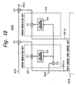
- Fig. 12 shows an example of the code changing unit 929 (similar to 818 as well).
- the synthesis signal 934 is supplied to a subtractor 31.
- a signal generated by a spread modulating unit 20 is supplied to the subtractor 31.
- the modulating unit 20 is constructed by a multiplier 21, an oscillator 23, and a PN code generator 24.
- the sync control signal 943 from the code reading unit 927 is supplied to the oscillator 23.
- An output of the oscillator 23 is supplied to the PN code generator 24 and the PN code in which a frequency and a phase are the same as those upon modulation is generated.
- Same information 941a as the copy control code extracted by the reading unit 927 is supplied from the control unit 928 to the multiplier 21. Therefore, by supplying an output of the multiplier 21 to the subtractor 31, the modulation copy control code included in the synthesis signal is erased.
- An output signal of the subtractor 31 is supplied to an adder 32.
- a signal generated by a spread modulating unit 40 is supplied to the adder 32.
- the modulating unit 40 is constructed by a multiplier 41 and a PN code generator 44.
- the output of the oscillator 23 of the modulating unit 20 is supplied to the PN code generator 44 and a PN code in which a frequency and a phase are the same as those upon modulation is generated.
- a copy control code 941b to be newly added is supplied from the control unit 928 to the multiplier 41. Therefore, by supplying an output of the multiplier 41 to the adder 32, the copy control code can be newly added.
- the copy control code is synthesized in an analogwise manner.
- information to be synthesized is not limited to the copy control code.
- the copyright management information is information that is necessary for a right management of the name of author, reversion of the right regarding a literary work, use conditions, identification number, and the like.
- the invention is not limited to the case of recording into the recording medium but can be also applied to a case of transmitting the analog information signal by a wire or a radio manner.
- addition information which was modulated by the spread spectrum can be also added to the analog information signal to be transmitted.
- the addition information is detected by the inverse spread spectrum and, on the basis of it, for example, the permission or inhibition of the reproduction of the analog information signal on the reception side is controlled.
- the copy control signal cannot be deleted by a filter or the like. So long as the synchronization cannot be obtained for the timing when the spread spectrum is performed, it is difficult to perform not only the detection of the copy control signal but also the detection of the addition of the signal. Therefore, according to the invention, the copy control can be certainly executed. According to the invention, since the spread spectrum processed signal is added, an influence by a deterioration or the like is hardly exerted on the original data. According to the invention as mentioned above, even after the digital signal was D/A converted, the copy control signal is not deleted.
- the copy can be prevented for the digital data recording apparatus which is connected in an analogwise manner and the copy control signal is also preserved even in the signal recorded in the analog recording apparatus.
Abstract
Description
- The present invention relates to information signal copying system and method. More particularly, the invention relates to a copy prevention system in which a signal is not lost even in a communication by an analog signal.
- There are some methods for copy prevention in a recording system of digital data, for example, a digital VTR (video tape recorder). One of them is a method of inhibiting a copy by adding a copy control signal to digital data. First, a principle of a copy prevention system will be described. In the accompanying drawings, Fig. 1 is a diagram showing the principle of the copy prevention system. In Fig. 1,
reference numeral 100 denotes a reproducing apparatus; 101 a recording medium for reproduction; 102 a reproducing unit; 110 a recording apparatus; 111 a recording unit; 112 a copy control signal detecting unit; 113 a recording medium for recording; 121 a read signal from therecording medium 101; 122 a reproduction signal which is supplied from the reproducingapparatus 100 to therecording apparatus 110; 123 a copy control signal; and 124 a write signal to therecording medium 113. - In the reproducing
apparats 100 constructed by therecording medium 101 for reproduction and the reproducingunit 102 in Fig. 1, a recording signal is read out from therecording medium 101 by the reproducingunit 102 and is outputted as a digital oranalog reproduction signal 122. On the other hand, in therecording apparatus 110 constructed by therecording unit 111, copy controlsignal detecting unit 112, and recordingmedium 113 for recording, the copy controlsignal detecting unit 112 detects thecopy control signal 123. In accordance with the detection result, therecording unit 111 generates thewrite signal 124 which inhibits or permits the recording to therecording medium 113 for recording. - The recording apparatus for recording a signal to the
recording medium 101 which is reproduced by the reproducingapparatus 100 will now be described. Fig. 2 is a block diagram of the recording apparatus by a digital signal. In Fig. 2,reference numeral 200 denotes an analog unit; 201 an information source from which information to be recorded is generated; and 210 a digital unit. Thedigital unit 210 comprises: anencoding unit 211, a copyprevention code generator 212, asynthesizer 213, awriting unit 214, and arecording medium 215. Ananalog information signal 231 is converted to adigital information signal 232 by an ADC (analog/digital converter) 221 and is supplied to thedigital unit 210. In thedigital unit 210, theencoding unit 211 encodes the digital information signal and supplies aninformation code 233 to thesynthesizer 213. Thesynthesizer 213 synthesizes theinformation code 233 and acopy prevention code 234 from the copyprevention code generator 212. Anoutput signal 235 from thesynthesizer 213 is supplied to thewriting unit 214 and anoutput signal 236 of thewriting unit 214 is recorded in therecording medium 215. Theinformation code 233 andcopy prevention code 234 are recorded in therecording medium 215. The system of Fig. 2 can be applied to, for example, a mastering of a read-only disk medium. - Fig. 3 shows another example of a recording apparatus for digitally recording. According to the example of Fig. 3, the copy prevention code is added in the
encoding unit 211. Theinformation code 233 from theencoding unit 211 is supplied to acode reading unit 216 and an addedcopy prevention code 237 is separated. The copy prevention code is supplied to acontrol unit 217 of the copy prevention code. Thecontrol unit 217 limits a generation of copy. For example, when the copy prevention code is a code for permitting a copy of one generation, thecontrol unit 217 generates acontrol signal 238 for rewriting the copy prevention code to a code for inhibiting the copy and acontrol signal 239 for instructing permission or inhibition of the recording of a signal to therecording medium 215 by thewriting unit 214. When the original copy prevention code permits the copy of one generation, thecontrol signal 238 is supplied to acode changing unit 218, the copy prevention code is changed to a code having the contents of inhibiting the copy, and the writing is permitted by thecontrol signal 239. The system of Fig. 3 can be applied to, for example, a digital VTR. - In a copy system using a digital medium, the operation in case of a digital connection and the operation in case of an analog connection are different. Examples in those cases will now be described, respectively. First, the digital connection will be described. Fig. 4 is a schematic diagram of a copy system by the digital connection.
Reference numeral 301 denotes a digital data reproducing apparatus; 302 a digital data recording apparatus; and 311 a digital signal. As for the operation of Fig. 4, thedigital signal 311 is supplied from the digitaldata reproducing apparatus 301 to the digitaldata recording apparatus 302 and the recording operation of the digitaldata recording apparatus 302 is controlled by the copy control signal included in thedigital signal 311. - Fig. 5 shows an example of the copy system by the digital connection. In Fig. 5,
reference numeral 400 denotes a reproducing apparatus; 401 a recording medium on the reproduction side; 402 a reading unit; 410 a digital interface; 411 a communication path; 420 a recording apparatus; 424 a copy prevention code reading unit; 425 a copy control signal control unit; 426 a code changing unit; 421 a writing unit; 423 a recording side recording medium; 431 a read signal; 432 a digital reproduction signal; 435 a copy prevention code which was read; 436 and 437 control signals; and 438 a write signal. - The operation of the construction of Fig. 5 will now be described. In the reproducing
apparatus 400 comprising therecording medium 401 for reproduction andreading unit 402, theread signal 431 obtained from therecording medium 401 is supplied to thereading unit 402 and is outputted as adigital reproduction signal 432. Thedigital reproduction signal 432 passes through thecommunication path 411 of thedigital interface 410 and is supplied to thecode reading unit 424 and thecopy prevention code 435 is separated. The copy controlsignal control unit 425 decodes the separated copy prevention code 433 and reads the information. Thecontrol signal 436 for changing the copy prevention code is outputted to thecode changing unit 426 and thecontrol signal 437 for instructing the permission or inhibition of the recording of the signal to therecording medium 425 is outputted to thewriting unit 421. In the construction of Fig. 5, not only the permission and inhibition of the recording but also the limitation of the copy about the generation can be performed. - The copy system by the analog connection will now be described. Fig. 6 shows a schematic construction.
Reference numeral 501 denotes a digital data reproducing apparatus; 502 a digital data recording apparatus; and 511 an analog signal transmitted between theapparatuses analog signal 511 which was D/A converted and outputted from the digitaldata reproducing apparatus 501 is inputted to the digitaldata recording apparatus 502 and is A/D converted and digitally recorded. In such a system, when the copy control signal has been extinguished in theanalog signal 511, the copy prevention control cannot be executed in the digitaldata recording apparatus 502. - A few methods have been proposed as a method of preventing the copy by an analog interface. For example, when the analog signal is a video signal, a phase of a color burst of an analog video signal to be outputted is partially inverted or a pseudo synchronization signal having an extremely large level is inserted as a sync signal for AGC, so that even if the normal reproduction can be performed. When the video signal is recorded by the VTR, a normal reproduction image is not obtained in a monitor receiver.
- In a conventional copy system, a digital copy prevention code is added to a signal in which an information source was digitally encoded. In case of a digital interface, therefore, the digital recording apparatus detects the copy control signal and can execute the copy prevention control. Even if the digital data reproducing apparatus is used, however, in case of an analog interface, the digital signal as a copy control signal added by the D/A conversion is dropped out. The copy control signal cannot be consequently detected in the digital recording apparatus in which the signal is finally recorded. The copy prevention control cannot be performed. Thus, it is necessary to prevent the copy by using the difference between the AGC methods of the VTR and the monitor receiver or the difference between the characteristics of the APC methods.
- As mentioned above, when executing the copy prevention by using the difference between the AGC methods of the VTR and the monitor receiver or the difference between the APC characteristics, there is a fear of occurrence of problems such that the copy cannot be prevented, a reproduction image of the monitor receiver is disturbed by a countermeasure for the copy prevention, or the like.
- US 5,319,735, upon which the precharacterising portions of appended
claims 1 and 16 are based, describes a process in which a code signal representing a sequence of code symbols carrying digital information is generated with the frequency components of the code signal being essentially confined to a preselected signalling band lying within the bandwidth of an audio signal within which the code signal is to be embedded. The audio signal is continuously frequency analysed over a frequency band encompassing the signalling band and the code signal is dynamically filtered as a function of the analysis thereby to provide a modified code signal with frequency components which are, at each time instant, essentially a preselected small proportion of the levels of the corresponding audio signal frequency components. Accordingly, the modified code signal can be combined with the audio signal to obtain a composite audio signal which is not readily distinguishable from the original audio signal by listening. Furthermore, the digital information can be recovered from the composite audio signal by a procedure which is essentially the compliment of that used to obtain the composite audio signal. - EP-A-0,618,723 describes a system in which a video signal is processed to selectively permit copying by superposing in that portion of the video signal which does not contain useful picture information a copyright information signal indicative of whether the viewable picture that is displayed from the video signal is subject to copyright and a copy generation signal indicative of the number of successive generations of copies that can be made from the video signal.
- It is an object of the invention to provide information signal recording apparatus and method, information signal copy system and method, and an information signal recording medium which can certainly prevent a copy in case of an analog interface and hardly exerts an influence such as deterioration or the like on an original signal in that case.
- According to the present invention, there is provided an apparatus for processing a synthesis signal of a main information and a sub information as defined in appended
claims 1 and a method of processing a synthesis signal of a main information and a sub information as defined in appended claim 16. - In the invention, since a band of the additional information such as a copy control signal or the like is widened by the spread spectrum and the addition information is added to the signal band of the information source, the copy control signal cannot be deleted by a filter or the like. Since the spread spectrum signal is added, an influence by a deterioration or the like is hardly exerted on the original data. Further, as long as no synchronization is obtained at a timing when the spread spectrum is performed, it is difficult to perform not only the detection of the addition of the signal but also the detection of the copy control signal. In addition, different codes can be used as a PN code which is used for the spread spectrum and a several kinds of orthogonal codes can be also multiplied. According to the invention, therefore, since the copy control signal is not erased even after the digital signal was D/A converted, the copy is prevented for the digital data recording apparatus which is connected in an analogwise manner. Since the copy control signal is not erased even in the signal recorded in the analog recording apparatus and the copy control signal cannot be deleted by a filter or the like, a very high effect of copy prevention can be obtained. Further, there is an advantage such that by multiplying the kind of spread spectrum and the orthogonal functions, an amount of information which can be added can be freely controlled.
- The invention will be further described by way of example, with reference to the accompanying drawings, in which:-
- Fig. 1 is a block diagram showing a principle of a copy prevention system;
- Fig. 2 is a block diagram of an example of a recording apparatus according to a digital signal of a copy control code;
- Fig. 3 is a block diagram of another example of a recording apparatus by a digital signal of a copy control code;
- Fig. 4 is a block diagram schematically showing a copy system by a digital connection;
- Fig. 5 is a block diagram of an example of the copy system by the digital connection;
- Fig. 6 is a block diagram schematically showing a copy system by an analog connection;
- Fig. 7 is a block diagram of an arrangement of a recording apparatus by an analog signal of a copy control code;
- Fig. 8 is a block diagram of an embodiment of a recording apparatus by an analog signal of a copy control code according to the invention;
- Fig. 9 is a block diagram of an arrangement of a copy system according to the invention;
- Fig. 10 is a block diagram of another embodiment of a copy system according to the invention;
- Fig. 11 is a block diagram showing a construction of an example of a code reading unit in another embodiment of the copy system according to the invention; and
- Fig. 12 is a block diagram showing a construction of an example of a code changing unit in another embodiment of the copy system according to the invention.
-
- An arrangement useful for an understanding of the invention will now be described hereinbelow with reference to the drawings. Fig. 7 is a diagram showing a construction of an embodiment of a recording apparatus according to the invention.
- In Fig. 7, an
analog unit 800 has aninformation source 801 for generating an information signal to be recorded and asynthesizer 802 for synthesizing aninformation signal 831 and acopy control code 833. Asynthesis signal 834 from thesynthesizer 802 is converted into a digital signal by an ADC (analog/digital converter) 821. The digital signal is supplied to adigital unit 810. - A copy control
code generating unit 811 generates acopy control code 832 to control a copy prevention. Thecopy control code 832 is supplied to aspread spectrum unit 812 and is spread spectrum processed. The spread spectrum processedcopy control code 833 is supplied to thesynthesizer 802. Asynthesis signal 835 which was converted into the digital signal is supplied to anencoding unit 813. Theencoding unit 813 encodes digital information and itsoutput 836 is supplied to awriting unit 814. Awrite signal 837 from thewriting unit 814 is recorded into arecording medium 815. By a construction of Fig. 8, the copy control code of the same band as that of the analog signal of the information source can be added. - Fig. 8 shows an embodiment of a recording apparatus according to the invention. As shown in Fig. 8, the
analog unit 800 includes: acode reading unit 816 for extracting the spread spectrum processed copy control code multiplexed to theanalog signal 831 from theinformation source 801; and acode changing unit 818 for changing the copy control code. Thecode changing unit 818 generates thesynthesis signal 834 in which the copy control code which was spread spectrum processed was multiplexed to the analog information signal. Thesynthesis signal 834 is converted into thedigital signal 835 by the ADC (analog/digital converter) 821. Thedigital signal 835 is supplied to theencoding unit 813 of thedigital unit 810. An output signal of theADC 821 is recorded into therecording medium 815 by thedigital unit 810 in a manner similar to the foregoing embodiment. As specific examples of the information to be recorded, there are audio information and/or video information. Therecording medium 815 is a tape-shaped or disk-shaped medium in which a digital signal can be optically or magnetically recorded. - A
copy control code 838 extracted by thecode reading unit 816 is supplied to a copy controlsignal control unit 817. Thecontrol unit 817 decodes the original copy control code and generates acopy control code 839 to be newly recorded. Thecopy control code 839 after the change is supplied to thecode changing unit 818 and the copy control code in thesynthesis signal 834 is changed. For example, when the original copy control code denotes that the copy is permitted or inhibited, the new copy control code is also made identical to the original copy control code. When the original copy control code denotes that the copy of one generation is permitted, the new copy control code is changed to a code indicative of the copy inhibition. - When an original
copy control signal 840 which is supplied from the copy controlsignal control unit 817 denotes the copy permission, thewriting unit 814 records an output of theencoding unit 813 into therecording medium 815. When thesignal 840 denotes the copy inhibition, thewriting unit 814 doesn't record the output of theencoding unit 813 to therecording medium 815. - As will be explained hereinlater, the
code reading unit 816 executes a process for an inverse spread spectrum and generates thecopy control code 838 and also generates the synthesis signal and acontrol signal 841 for synchronization control to thecode changing unit 818. As will be explained hereinlater, thecode changing unit 818 erases the original copy control code by the inverse spread spectrum and, subsequently, synthesizes the newcopy control code 839 by the spread spectrum. Thecode changing unit 818 receives thecontrol signal 841 which is used for the synchronization control that is executed for the inverse spread spectrum from thecode reading unit 816. - The copy control code is, for example, a code of two bits and is information to instruct a control about the copy as shown below.
- 00:
- can be copied
- 01:
- undefined
- 10:
- copy of one generation can be performed
- 11:
- copy is inhibited
- A copy system using a recording medium in which the synthesis signal to which the copy control code had been multiplexed has digitally been recorded by the construction of Fig. 7 or 8 will now be described with reference to Fig. 9. In Fig. 9, a reproducing
apparatus 900 reproduces arecording medium 901 in which a synthesis signal has digitally been recorded. - In the reproducing
apparatus 900, aread signal 931 outputted from therecording medium 901 for reproduction is set to adigital reproduction signal 932 by areading unit 902 and is inputted to adecoding unit 903 and is decoded into adigital decoding signal 933 by thedecoding unit 903. Further, thesignal 933 is converted into ananalog synthesis signal 934 by a DAC (digital/analog converter) 904. Theanalog synthesis signal 934 is supplied to anADC 921 and an inversespread spectrum unit 923 in arecording apparatus 920 through acommunication path 911 of ananalog interface 910. A copy control code which was spread spectrum processed has been added to theanalog synthesis signal 934. - In the
recording apparatus 920, a digital information signal 935 from theADC 921 is encoded by anencoding unit 922. Anencoding signal 936 from theencoding unit 922 is supplied to awriting unit 925. Awrite signal 939 from thewriting unit 925 is recorded into arecording medium 926 for recording. Asignal 937 which was inversely spread by the inversespread spectrum unit 923 is inputted to a copy control code detecting unit 924 and a copy control code 938 is detected. Thewriting unit 925 is controlled by the copy control code 938. When the copy is permitted in accordance with the copy control code 938, the writing is performed. When the copy is inhibited, the writing is inhibited. As mentioned above, by adding the copy control signal to the same band as that of the information source signal in an analogwise manner by the spread spectrum, there is obtained an effect such that even in the digital data recording apparatus connected in an analogwise manner, the recording can be controlled without extinguishing the copy control signal. - Fig. 10 shows another embodiment of a copy system according to the invention. In a manner similar to the arrangement of Fig. 9, the reproducing
apparatus 900 reproduces therecording medium 901, generates theanalog synthesis signal 934 in which the analog information signal and the copy control code have been synthesized, and supplies thesignal 934 to therecording apparatus 920 through thecommunication path 911 of theanalog interface 910. - The
analog synthesis signal 934 is supplied to acode reading unit 927 of therecording apparatus 920 and a multiplexedcopy control code 940 is extracted. Acode changing unit 929 to change the copy control code is provided. Thecode changing unit 929 generates asynthesis signal 945 in which the spread spectrum processed copy control code has been multiplexed to the analog information signal. Thesynthesis signal 945 is converted into thedigital signal 935 by theADC 921. The digital signal is supplied to theencoding unit 922. In a manner similar to the foregoing embodiment, the output signal of theADC 921 is recorded into therecording medium 926 by theencoding unit 922. - The
copy control code 940 extracted by thecode reading unit 927 is supplied to a copy controlcode control unit 928. Thecontrol unit 928 decodes the originalcopy control code 940 and generates acopy control code 941 to be newly recorded. Thecopy control code 941 after the change is supplied to thecode changing unit 929 and the copy control code in thesynthesis signal 945 is changed. For example, when the original copy control code indicates the copy permission or copy inhibition, the new copy control code is also made identical to the original copy control code. When the original copy control code denotes the permission of the copy of one generation, the new copy control code is changed to the code indicative of the copy inhibition. - As will be explained hereinlater, the
code reading unit 927 executes a process of the inverse spread spectrum, generates thecopy control code 940, and also generates the synthesis signal and acontrol signal 943 which is used for synchronization control to thecode changing unit 929. As will be explained hereinlater, thecode changing unit 929 erases the original control code by the inverse spread spectrum which was sync controlled by thecontrol signal 943 and, subsequently, synthesizes the newcopy control code 941 by the spread spectrum. - Fig. 11 shows an example of the code reading unit 927 (similar to 816 as well). The
synthesis signal 934 is supplied to amultiplier 11 and async control circuit 12. A PN (pseudo noise) code from aPN code generator 14 is supplied to themultiplier 11 andsync control circuit 12. Thesync control circuit 12 extracts thetiming signal 943 by using a fact that the PN code has a steep autocorrelation. An oscillating frequency and a phase of anoscillator 13 are controlled by the extractedtiming signal 943 and an output signal of theoscillator 13 is supplied to thePN code generator 14. The PN code generated from the output of theoscillator 13 which was sync controlled and thesynthesis signal 934 are multiplied by themultiplier 11, so that the demodulatedcopy control code 940 is derived from themultiplier 11. Thecopy control code 940 is supplied to thecontrol unit 928. - As a PN code, an M sequence (maximum length sequence), GOLD code, or the like can be used. In case of the M sequence, for example, the former half sequence of its period and one bit on the lower significant side of the copy control code (two bits) are multiplied. The latter half sequence of the period and one bit on the higher significant side are multiplied and the modulation of the spread spectrum is executed. A way of modulating the copy control code by the spread spectrum is not limited to such an example but other various methods can be used. For example, after the copy control code was linear-modulated, the spread spectrum modulation can be also performed. The invention is not limited to the direct modulation but the signal can be also modulated by a frequency hopping method or a time hopping method. Further, different PN codes can be also used for the spread spectrum and a few kinds of orthogonal codes can be also multiplied.
- Fig. 12 shows an example of the code changing unit 929 (similar to 818 as well). The
synthesis signal 934 is supplied to asubtractor 31. A signal generated by aspread modulating unit 20 is supplied to thesubtractor 31. The modulatingunit 20 is constructed by amultiplier 21, anoscillator 23, and aPN code generator 24. The sync control signal 943 from thecode reading unit 927 is supplied to theoscillator 23. An output of theoscillator 23 is supplied to thePN code generator 24 and the PN code in which a frequency and a phase are the same as those upon modulation is generated. Same information 941a as the copy control code extracted by thereading unit 927 is supplied from thecontrol unit 928 to themultiplier 21. Therefore, by supplying an output of themultiplier 21 to thesubtractor 31, the modulation copy control code included in the synthesis signal is erased. - An output signal of the
subtractor 31 is supplied to anadder 32. A signal generated by aspread modulating unit 40 is supplied to theadder 32. The modulatingunit 40 is constructed by amultiplier 41 and aPN code generator 44. The output of theoscillator 23 of the modulatingunit 20 is supplied to thePN code generator 44 and a PN code in which a frequency and a phase are the same as those upon modulation is generated. Acopy control code 941b to be newly added is supplied from thecontrol unit 928 to themultiplier 41. Therefore, by supplying an output of themultiplier 41 to theadder 32, the copy control code can be newly added. - According to the above embodiment, the copy control code is synthesized in an analogwise manner. In the invention, however, information to be synthesized is not limited to the copy control code. For example, it is also possible to modulate copyright management information by the spread spectrum together with the copy control code and to multiplex the resultant modulated information to the analog information signal. The copyright management information is information that is necessary for a right management of the name of author, reversion of the right regarding a literary work, use conditions, identification number, and the like.
- Further, the invention is not limited to the case of recording into the recording medium but can be also applied to a case of transmitting the analog information signal by a wire or a radio manner. Namely, addition information which was modulated by the spread spectrum can be also added to the analog information signal to be transmitted. On the reception side, the addition information is detected by the inverse spread spectrum and, on the basis of it, for example, the permission or inhibition of the reproduction of the analog information signal on the reception side is controlled.
- According to the invention, by spread spectrum processing the addition information such as a copy control signal or the like, the band is widened and the addition information is added to the signal band of the information source, the copy control signal cannot be deleted by a filter or the like. So long as the synchronization cannot be obtained for the timing when the spread spectrum is performed, it is difficult to perform not only the detection of the copy control signal but also the detection of the addition of the signal. Therefore, according to the invention, the copy control can be certainly executed. According to the invention, since the spread spectrum processed signal is added, an influence by a deterioration or the like is hardly exerted on the original data. According to the invention as mentioned above, even after the digital signal was D/A converted, the copy control signal is not deleted. Therefore, the copy can be prevented for the digital data recording apparatus which is connected in an analogwise manner and the copy control signal is also preserved even in the signal recorded in the analog recording apparatus. There is a very high copy prevention effect. Further, by multiplying the kind of spread spectrum and the orthogonal functions, an amount of information which can be added can be freely controlled.
- The present invention is not limited to the foregoing embodiments but many modifications and variations are possible within the scope of the appended claims of the invention.
Claims (30)
- An apparatus for processing a synthesis signal of a main information and a sub information, which was spread spectrum processed, comprising:first providing means (14) for providing first code used for detecting said sub-information from said synthesis signal (934);detecting means (11) for detecting said sub-information (940) using said generated first code by executing an inverse spread spectrum process to said synthesis signal; andupdate means (928) for detecting a sub-information status from said detected sub-information and determining an updated sub-information status of said main information; characterised by:second providing means (44) for providing second code different from said first code used for indicating said updated sub-information status of said main information and same as code used for detecting said updated sub-information; andnew synthesis signal generating means (41, 32) for generating a new synthesis signal from said updated sub-information, which was spread spectrum processed using said second code provided, and said synthesis signal.
- An apparatus according to claim 1, wherein said sub information indicates copy control information (838,940;839,941).
- An apparatus according to claim 2, wherein said update means (817,928) determines said updated sub-information status to a "copy inhibition" status, when said detected sub-information status indicates a "copy of one generation can be performed" status.
- An apparatus according to claim 1, 2 or 3, further comprising
recording control means (814,925) for controlling recording to a recording medium (815,926) based on said detected sub-information status (838,940). - An apparatus according to claim 1, wherein said sub-information indicates at least one of an author information regarding said main information, a reversion information of the right regarding said main information, a use condition information of said main information, and an identification information of said main information.
- An apparatus according to any preceding claim, wherein said new synthesis signal generating means comprises:removing means (31) for removing said sub information (838,940) from said synthesis signal (934); andadding means (32) for adding a signal (839, 941) indicating said updated sub-information status to said synthesis signal (934) from which said sub information (838,940) was removed.
- An apparatus according to claim 6, wherein said removing means (31) removes said sub information (838,940) from said synthesis signal (934) using said first code provided from said first providing means.
- An apparatus according to claim 7, wherein said removing means (31) executes a spread spectrum process to said detected sub-information (838, 940) using the same spread code as the spread code used for synthesizing said sub-information to said main information and removes said sub-information (838, 940) from said synthesis signal (934) using said sub-information which was spread spectrum.
- An apparatus according to any preceding claim, further comprising
timing generating means (12,13) for generating timing signal from said synthesis signal; wherein
said first providing means (816,927,14) provides said first code with timing based on said timing signal. - An apparatus according to claim 9, wherein
said sub-information is synthesized to said main information using code same as said first code; and
said timing generating means (12,13) generates said timing signal using a characteristic that spread codes have a steep autocorrelation. - An apparatus according to claim 9 or 10, wherein
said second providing means (818,929,23,41,44) provides said second code with timing based on said timing signal. - An apparatus according to claim 9, 10 or 11, wherein said new synthesis signal generating means (818,929, 21,23,24) removing said sub-information (828,940) using said first code generated with timing based on said timing signal.
- An apparatus according to claim 1, further comprising encoding means (813,922) for encoding said new synthesis signal (834,945).
- An apparatus according to claim 1, wherein
said detecting means comprises extracting means (816,927,14) for extracting said sub-information by executing an inverse spread spectrum process to said synthesis signal, thereby forming an extracted sub-information (838,940);
said update means comprises control means (817,928) for changing said extracted sub information based on an updated sub information status, thereby forming a changed sub-information (839,941); and
said new synthesis signal generating means comprises spread spectrum means (818,929) for executing a spread spectrum process to said changed sub information and
synthesis means (818,929,31,32) for generating a new synthesis signal (834,945) from said changed sub information which was spread spectrum processed and said synthesis signal. - An apparatus according to claim 1, wherein
said first providing means comprises code generating means for generating first code same as code used for synthesizing said main information and said sub-information;
said detecting means comprises extracting means (816,927) for extracting said sub information from said synthesis signal using said generated first code, thereby forming a extracted sub-information;
said update means comprises control means (817,928) for changing said sub information from said extracting means based on an updated sub information status, thereby forming a changed sub information; and
said new synthesis signal generating means comprises modulating means (40) for modulating said changed sub information using said generated second code, and synthesis means (31,32) for generating a new synthesis signal from said modulated changed sub information and said synthesis signal. - A method of processing a synthesis signal of a main information and a sub-information, which was spread spectrum processed, comprising:providing first code used for detecting said sub-information from said synthesis signal (934);detecting said sub-information (940) using said generated first code by executing an inverse spread spectrum process to said synthesis signal; anddetecting a sub-information status from said detected sub-information and determining an updated sub-information status of said main information; characterised byproviding second code different from said first code used for indicating said updated sub-information status of said main information and same as code used for detecting said updated sub-information; andgenerating a new synthesis signal from said updated sub-information, which was spread spectrum processed using said second code provided, and said synthesis signal.
- The method according to claim 16, wherein
said sub-information indicates copy control information (838,940;839,941). - The method according to claim 17, comprising
determining said updated sub-information status to a "copy inhibition" status, when said detected sub-information status indicates a "copy of one generation can be performed" status. - The method according to claim 16, 17 or 18, further comprising controlling (814,925) recording to a recording medium (815,926) based on said detected sub information status (838,940).
- The method according to claim 16, wherein
said sub-information indicates at least one of an author information regarding said main information, a reversion information of the right regarding said main information, a use condition information of said main information, and an identification information of said main information. - The method according to any one of claims 16 to 20, wherein said step of generating comprises:removing (31) said sub information (838,940) from said synthesis signal (934); andadding (32) a signal (839, 940) indicating said updated sub-information status to said synthesis signal (934) from which said sub information (838,940) was removed.
- The method according to claim 21, wherein said step of removing (31) removes said sub information (838,940) from said synthesis signal (934) using said first code provided from said step of providing first code.
- The method according to claim 22, wherein
said step of removing (31) executes a spread spectrum process to said detected sub-information (83 8,940) using the same spread code as the spread code used for synthesizing said sub- information to said main information and removes said sub-information (838, 940) from said synthesis signal (934) using said sub-information which was spread spectrum. - The method according to any one of claims 16 to 23, further comprising generating (12,13) a timing signal from said synthesis signal; wherein
said step of providing first code provides said first code with timing based on said timing signal. - The method according to claim 24, wherein said sub-information is synthesized to said main information using code same as said first code; and
said step of generating timing (12,13) generates said timing signal using a characteristic that spread codes have a steep autocorrelation. - The method according to claim 24 or 25, wherein
said step of providing second code provides said second code with timing based on said timing signal. - The method according to claim 24, 25 or 26, wherein
said step of generating removes said sub-information (828,940) using said first code generated with timing based on said timing signal. - The method according to claim 16, further comprising
encoding (813,922) said new synthesis signal (834,945). - A method according to claim 16, wherein
said step of detecting said sub-information comprises extracting (816,927,14) said sub-information by executing an inverse spread spectrum process to said synthesis signal, thereby forming an extracted sub-information (838,940);
said step of detecting a sub-information status comprises changing (817,928) said extracted sub-information based on an updated sub-information status, thereby forming a changed sub-information (839,941); and
said step of generating comprises executing (818,929) a spread spectrum process to said changed sub-information, and generating (818,929,31,32) a new synthesis signal (834,945) from said changed sub-information which was spread spectrum processed and said synthesis signal. - A method according to claim 16, wherein
said step of providing first code comprises generating a first code same as code used for synthesizing said main information and said sub-information;
said step of detecting said sub-information comprises extracting (816,927) said sub information from said synthesis signal using said generated first code, thereby forming an extracted sub-information;
said step of detecting a sub-information status comprises changing (817,928) said sub information from said extracting means based on an updated sub-information status, thereby forming a changed sub information; and
said step of generating comprises modulating (40) said changed sub-information using said generated second code; and generating (31,32) a new synthesis signal from said modulated changed sub information and said synthesis signal.
Applications Claiming Priority (3)
| Application Number | Priority Date | Filing Date | Title |
|---|---|---|---|
| JP339959/95 | 1995-12-04 | ||
| JP33995995 | 1995-12-04 | ||
| JP33995995A JP3371187B2 (en) | 1995-12-04 | 1995-12-04 | Information signal recording apparatus and method, and information signal duplication apparatus and method |
Publications (3)
| Publication Number | Publication Date |
|---|---|
| EP0778566A2 EP0778566A2 (en) | 1997-06-11 |
| EP0778566A3 EP0778566A3 (en) | 1997-12-17 |
| EP0778566B1 true EP0778566B1 (en) | 2003-03-26 |
Family
ID=18332390
Family Applications (1)
| Application Number | Title | Priority Date | Filing Date |
|---|---|---|---|
| EP96308568A Expired - Lifetime EP0778566B1 (en) | 1995-12-04 | 1996-11-27 | Apparatus and method for synthesising an information signal and a reproduction control signal and information signal recording apparatus |
Country Status (11)
| Country | Link |
|---|---|
| US (1) | US5982977A (en) |
| EP (1) | EP0778566B1 (en) |
| JP (1) | JP3371187B2 (en) |
| KR (1) | KR100484208B1 (en) |
| CN (1) | CN1161988C (en) |
| AT (1) | ATE235735T1 (en) |
| CA (1) | CA2191667C (en) |
| DE (1) | DE69626936T2 (en) |
| ES (1) | ES2192218T3 (en) |
| ID (1) | ID17086A (en) |
| TW (1) | TW353174B (en) |
Cited By (1)
| Publication number | Priority date | Publication date | Assignee | Title |
|---|---|---|---|---|
| US8248506B2 (en) | 1998-07-17 | 2012-08-21 | Sony Corporation | Imaging apparatus |
Families Citing this family (57)
| Publication number | Priority date | Publication date | Assignee | Title |
|---|---|---|---|---|
| US6611607B1 (en) | 1993-11-18 | 2003-08-26 | Digimarc Corporation | Integrating digital watermarks in multimedia content |
| US5748763A (en) | 1993-11-18 | 1998-05-05 | Digimarc Corporation | Image steganography system featuring perceptually adaptive and globally scalable signal embedding |
| US6944298B1 (en) | 1993-11-18 | 2005-09-13 | Digimare Corporation | Steganographic encoding and decoding of auxiliary codes in media signals |
| US6614914B1 (en) | 1995-05-08 | 2003-09-02 | Digimarc Corporation | Watermark embedder and reader |
| US6983051B1 (en) | 1993-11-18 | 2006-01-03 | Digimarc Corporation | Methods for audio watermarking and decoding |
| JP3528394B2 (en) * | 1996-01-23 | 2004-05-17 | ソニー株式会社 | Data recording / reproducing device |
| JP3695016B2 (en) * | 1996-10-15 | 2005-09-14 | ソニー株式会社 | Video signal processing apparatus and video signal processing method |
| JP3778236B2 (en) * | 1996-10-22 | 2006-05-24 | ソニー株式会社 | Video signal transmission method, video signal output method, video signal output device, and additional information detection device |
| JP3707165B2 (en) * | 1996-11-01 | 2005-10-19 | ソニー株式会社 | Video transmission method, video processing method, video transmission device, and video processing device |
| JP3736588B2 (en) * | 1996-11-18 | 2006-01-18 | ソニー株式会社 | Information output apparatus, information output method, recording apparatus, and information duplication prevention control method |
| JPH10172235A (en) * | 1996-12-09 | 1998-06-26 | Sony Corp | Method for information recording updating, apparatus therefor, recording medium initializing apparatus and recording medium |
| JPH10174063A (en) * | 1996-12-10 | 1998-06-26 | Sony Corp | Video signal transmitting method, superimposed information extracting method, video signal output device, video signal receiver and video signal recording medium |
| TW401702B (en) * | 1997-01-20 | 2000-08-11 | Sony Corp | Image signal transmitting method, superimposed signal extracting method, image signal output apparatus, image signal receiving apparatus and image signal recording medium |
| JP3867738B2 (en) * | 1997-01-22 | 2007-01-10 | ソニー株式会社 | Video signal transmission method and superimposed information extraction method |
| JP3901268B2 (en) * | 1997-01-23 | 2007-04-04 | ソニー株式会社 | Information signal output control device, information signal output control method, information signal duplication prevention device, and information signal duplication prevention method |
| KR100238082B1 (en) * | 1997-04-14 | 2000-01-15 | 윤종용 | Recorder for automatically selecting recording mode |
| JPH1145556A (en) * | 1997-05-29 | 1999-02-16 | Sony Corp | Device and method for recording audio data |
| JPH1145548A (en) * | 1997-05-29 | 1999-02-16 | Sony Corp | Method and device for recording audio data, and transmission method of audio data |
| JPH10336578A (en) | 1997-06-05 | 1998-12-18 | Sony Corp | Information addition method for video signal, additional information detection method and device for the same |
| JPH10340531A (en) * | 1997-06-10 | 1998-12-22 | Sony Corp | Device, method and medium of recording information signal |
| US6356704B1 (en) | 1997-06-16 | 2002-03-12 | Ati Technologies, Inc. | Method and apparatus for detecting protection of audio and video signals |
| EP0886274A3 (en) * | 1997-06-17 | 1999-09-08 | Sony Corporation | Information signal processing unit |
| US6430356B1 (en) * | 1997-06-27 | 2002-08-06 | Victor Company Of Japan, Ltd. | Information recording and reproducing apparatus for dubbing an audio-visual digital signal and auxiliary information recorded in a magnetic tape |
| JPH1175165A (en) | 1997-08-29 | 1999-03-16 | Sony Corp | Detection method and device for spread spectrum signal |
| JPH1175166A (en) * | 1997-08-29 | 1999-03-16 | Sony Corp | Superimposition method and device for additional information to video signal |
| JPH1173725A (en) * | 1997-08-29 | 1999-03-16 | Sony Corp | Information signal recording/reproducing system, information recording device, information signal reproducing device and information signal recording/ reproducing method |
| JP4045381B2 (en) * | 1997-08-29 | 2008-02-13 | ソニー株式会社 | Method and apparatus for superimposing additional information on video signal |
| JP4456185B2 (en) * | 1997-08-29 | 2010-04-28 | 富士通株式会社 | Visible watermarked video recording medium with copy protection function and its creation / detection and recording / playback device |
| JP4003096B2 (en) * | 1997-09-01 | 2007-11-07 | ソニー株式会社 | Method and apparatus for superimposing additional information on video signal |
| JP3867744B2 (en) * | 1997-09-01 | 2007-01-10 | ソニー株式会社 | Spread spectrum signal detection method and apparatus |
| TW398116B (en) * | 1997-09-01 | 2000-07-11 | Sony Corp | Method and apparatus for detecting spectrum spread signals |
| JP3750707B2 (en) * | 1997-09-02 | 2006-03-01 | ソニー株式会社 | Spread spectrum signal detection method and apparatus |
| JPH1188848A (en) | 1997-09-02 | 1999-03-30 | Sony Corp | Method and system for superimposing and transmitting additional information, device for superimposing and detecting additional information and storage medium |
| JP3775016B2 (en) * | 1997-09-02 | 2006-05-17 | ソニー株式会社 | Transmission and / or recording apparatus, reception and / or reproduction apparatus, transmission / reception / recording / reproduction apparatus, transmission / reception system, transmission and / or recording method, reception and / or reproduction method, transmission method, and recording medium |
| JP4003098B2 (en) * | 1997-09-17 | 2007-11-07 | ソニー株式会社 | Information addition method and information addition apparatus for image signal |
| JP3956479B2 (en) | 1998-04-27 | 2007-08-08 | ソニー株式会社 | Mobile communication system, mobile station and base station |
| JPH11328851A (en) * | 1998-05-19 | 1999-11-30 | Sony Corp | Terminal device and reproduction method |
| JP2000013585A (en) * | 1998-06-19 | 2000-01-14 | Sony Corp | Superimposing device and method for additional information, image information recorder and its method |
| US6976265B1 (en) * | 1998-10-08 | 2005-12-13 | Ati International Srl | Method and apparatus for controlling display of content signals |
| CA2288366A1 (en) | 1998-11-05 | 2000-05-05 | Akira Ogino | Additional information transmission method, additional information transmission system, information signal output apparatus, information signal processing apparatus, information signal recording apparatus and information signal recording medium |
| JP3868643B2 (en) | 1998-12-03 | 2007-01-17 | 株式会社日立製作所 | Digital information duplication restriction method, digital information duplication restriction device, and digital information recording device |
| EP2665062A3 (en) | 1998-12-11 | 2016-10-19 | Sony Corporation | Technique for controlling copying of data |
| US20070100757A1 (en) | 1999-05-19 | 2007-05-03 | Rhoads Geoffrey B | Content Protection Arrangements |
| US6690880B1 (en) * | 1999-05-21 | 2004-02-10 | Ati International, Srl | Method and apparatus for copy protection detection in a video signal |
| JP2001067792A (en) | 1999-08-30 | 2001-03-16 | Sony Corp | Device and metod for recording and recording medium |
| JP3728621B2 (en) * | 2000-02-10 | 2005-12-21 | 松下電器産業株式会社 | Digital data copy control method and playback apparatus |
| US6845170B2 (en) | 2001-01-11 | 2005-01-18 | Sony Corporation | Watermark resistant to resizing and rotation |
| JP4512280B2 (en) * | 2001-02-16 | 2010-07-28 | 日立コンシューマエレクトロニクス株式会社 | Stream data playback device |
| US6865273B2 (en) | 2002-06-05 | 2005-03-08 | Sony Corporation | Method and apparatus to detect watermark that are resistant to resizing, rotation and translation |
| US7602936B2 (en) | 2001-03-08 | 2009-10-13 | Sony Corporation | Method to make wavelet watermarks resistant to affine transformations |
| US8122465B2 (en) * | 2001-07-05 | 2012-02-21 | Digimarc Corporation | Watermarking to set video usage permissions |
| US7263202B2 (en) | 2001-07-05 | 2007-08-28 | Digimarc Corporation | Watermarking to control video recording |
| EP1442454A4 (en) * | 2001-11-01 | 2006-03-08 | Mattel Inc | Digital audio device |
| US7433489B2 (en) | 2001-11-28 | 2008-10-07 | Sony Electronics Inc. | Method to ensure temporal synchronization and reduce complexity in the detection of temporal watermarks |
| US7317811B2 (en) | 2001-11-28 | 2008-01-08 | Sony Electronics Inc. | Method to decode temporal watermarks in compressed video |
| JP2003186500A (en) * | 2001-12-17 | 2003-07-04 | Sony Corp | Information transmission system, information encoding device and information decoding device |
| US8929011B1 (en) * | 2013-10-14 | 2015-01-06 | Lsi Corporation | Sync mark system for two dimensional magnetic recording |
Family Cites Families (13)
| Publication number | Priority date | Publication date | Assignee | Title |
|---|---|---|---|---|
| GB1572622A (en) * | 1977-03-29 | 1980-07-30 | Secr Defence | Code synchronising apparatus |
| JPH0731877B2 (en) * | 1985-07-03 | 1995-04-10 | 株式会社日立製作所 | Information recording / reproducing method and apparatus |
| KR930008167B1 (en) * | 1986-08-11 | 1993-08-26 | 매크로비젼 코포레이션 | Method and apparatus for preventing the copying of a video program |
| DE3851724T2 (en) * | 1987-07-08 | 1995-05-04 | Matsushita Electric Ind Co Ltd | Method and device for protecting copy signals. |
| JP2845915B2 (en) * | 1989-01-06 | 1999-01-13 | 株式会社日立製作所 | Information reproducing method and information reproducing apparatus |
| US5134496A (en) * | 1989-05-26 | 1992-07-28 | Technicolor Videocassette Of Michigan Inc. | Bilateral anti-copying device for video systems |
| JP3114263B2 (en) * | 1991-07-29 | 2000-12-04 | ソニー株式会社 | Video signal recording system |
| US5319735A (en) * | 1991-12-17 | 1994-06-07 | Bolt Beranek And Newman Inc. | Embedded signalling |
| JP3049155B2 (en) * | 1992-06-15 | 2000-06-05 | 株式会社リコー | Optical disc reproducing method and apparatus therefor |
| JP2618571B2 (en) * | 1992-09-24 | 1997-06-11 | 富士通株式会社 | Data reproduction circuit for magneto-optical disk |
| US5315448A (en) * | 1993-03-18 | 1994-05-24 | Macrovision Corporation | Copy protection for hybrid digital video tape recording and unprotected source material |
| JP3250333B2 (en) * | 1993-04-02 | 2002-01-28 | ソニー株式会社 | Video signal processing method, video signal recording method, video signal reproduction method, video signal processing device, video signal recording device, and video signal reproduction device |
| JP3321972B2 (en) * | 1994-02-15 | 2002-09-09 | ソニー株式会社 | Digital signal recording device |
-
1995
- 1995-12-04 JP JP33995995A patent/JP3371187B2/en not_active Expired - Fee Related
-
1996
- 1996-11-22 US US08/755,101 patent/US5982977A/en not_active Expired - Lifetime
- 1996-11-27 AT AT96308568T patent/ATE235735T1/en active
- 1996-11-27 DE DE69626936T patent/DE69626936T2/en not_active Expired - Lifetime
- 1996-11-27 EP EP96308568A patent/EP0778566B1/en not_active Expired - Lifetime
- 1996-11-27 ES ES96308568T patent/ES2192218T3/en not_active Expired - Lifetime
- 1996-11-29 TW TW085114759A patent/TW353174B/en not_active IP Right Cessation
- 1996-11-29 CA CA002191667A patent/CA2191667C/en not_active Expired - Fee Related
- 1996-12-02 ID IDP963567A patent/ID17086A/en unknown
- 1996-12-02 KR KR1019960061085A patent/KR100484208B1/en not_active IP Right Cessation
- 1996-12-04 CN CNB961233915A patent/CN1161988C/en not_active Expired - Fee Related
Cited By (3)
| Publication number | Priority date | Publication date | Assignee | Title |
|---|---|---|---|---|
| US8248506B2 (en) | 1998-07-17 | 2012-08-21 | Sony Corporation | Imaging apparatus |
| US8830355B2 (en) | 1998-07-17 | 2014-09-09 | Sony Corporation | Imaging apparatus |
| US9210340B2 (en) | 1998-07-17 | 2015-12-08 | Sony Corporation | Imaging apparatus |
Also Published As
| Publication number | Publication date |
|---|---|
| ATE235735T1 (en) | 2003-04-15 |
| US5982977A (en) | 1999-11-09 |
| KR100484208B1 (en) | 2005-08-17 |
| CA2191667A1 (en) | 1997-06-05 |
| TW353174B (en) | 1999-02-21 |
| EP0778566A3 (en) | 1997-12-17 |
| DE69626936T2 (en) | 2004-02-05 |
| DE69626936D1 (en) | 2003-04-30 |
| CN1161620A (en) | 1997-10-08 |
| KR970050856A (en) | 1997-07-29 |
| JP3371187B2 (en) | 2003-01-27 |
| ID17086A (en) | 1997-12-04 |
| EP0778566A2 (en) | 1997-06-11 |
| CA2191667C (en) | 2005-07-12 |
| JPH09163341A (en) | 1997-06-20 |
| CN1161988C (en) | 2004-08-11 |
| ES2192218T3 (en) | 2003-10-01 |
Similar Documents
| Publication | Publication Date | Title |
|---|---|---|
| EP0778566B1 (en) | Apparatus and method for synthesising an information signal and a reproduction control signal and information signal recording apparatus | |
| CN1127851C (en) | Information output device, information recording device, informaion duplication control system and recording medium of the same | |
| US6282654B1 (en) | Information signal recording/reproducing system, information signal recording device, information signal reproducing device and information signal recording/reproducing process | |
| US20020150246A1 (en) | Additional information embedding device and additional information embedding method | |
| EP1032205B1 (en) | Additional information embedding and detecting method and apparatus | |
| KR100829177B1 (en) | Content data, record medium, recording method, recording apparatus, reproducing method, and reproducing apparatus | |
| US6526510B1 (en) | Signal reproducing method and apparatus, signal recording method and apparatus and signal recording system | |
| KR20000006035A (en) | Copy generation management method, information signal reproducing method, information signal reproducing apparatus, and information signal recording apparatus | |
| KR20000035263A (en) | Additional information transmission method, Additional information transmission system, information signal output apparatus, information signal processing apparatus, information signal recording apparatus and information signal recording medium | |
| KR20000052380A (en) | Information signal copyright protection method information signal, recording method and device, and information signal, output method and device background of the invention | |
| JPH10200504A (en) | Information signal transmission method, copy prevention control method, information signal output device, information signal recorder and information signal recording medium | |
| US6381262B1 (en) | Information signal processing unit | |
| US20010007608A1 (en) | Information transmission method, information duplication prohibiting method, information duplication prohibiting device and information crevording medium | |
| US6782191B1 (en) | Additional information superposing method, information signal copy control method, information signal output device and information signal recording device | |
| JP3867738B2 (en) | Video signal transmission method and superimposed information extraction method | |
| KR970071714A (en) | A recording medium having a copy protection signal superimposed on a main signal, a device for reproducing the recording medium, a device for recording a copy protection signal on the recording medium, and a digital signal having the superimposed copy protection signal Device | |
| US20010053279A1 (en) | Video signal transmission method, superimposed information extraction method, video signal output device, video signal receiving device, and video recording medium | |
| KR100693455B1 (en) | Spectral spread signal detection method and apparatus | |
| KR100717251B1 (en) | Record carrier carrying a stereo signal and a data signal | |
| US6427047B1 (en) | Apparatus and method for protecting the unauthorized duplication of a signal | |
| MXPA96006067A (en) | Apparatus and method for synthesizing information signs and reproduction control signals, and apparatus for recording information signals | |
| US6359905B1 (en) | Method and apparatus of detecting spectrum spread signal | |
| JP3888401B2 (en) | Information signal output device, information signal output method, information signal reproduction device, and information signal reproduction method | |
| JPH0746535A (en) | Digital signal recording device and digital signal reproducing device | |
| JPH10334593A (en) | Information signal recording control method, information signal processing device and information signal recording medium |
Legal Events
| Date | Code | Title | Description |
|---|---|---|---|
| PUAI | Public reference made under article 153(3) epc to a published international application that has entered the european phase |
Free format text: ORIGINAL CODE: 0009012 |
|
| AK | Designated contracting states |
Kind code of ref document: A2 Designated state(s): AT DE ES FR GB IT NL |
|
| PUAL | Search report despatched |
Free format text: ORIGINAL CODE: 0009013 |
|
| AK | Designated contracting states |
Kind code of ref document: A3 Designated state(s): AT DE ES FR GB IT NL |
|
| 17P | Request for examination filed |
Effective date: 19980514 |
|
| 17Q | First examination report despatched |
Effective date: 20000629 |
|
| GRAH | Despatch of communication of intention to grant a patent |
Free format text: ORIGINAL CODE: EPIDOS IGRA |
|
| RTI1 | Title (correction) |
Free format text: APPARATUS AND METHOD FOR SYNTHESISING AN INFORMATION SIGNAL AND A REPRODUCTION CONTROL SIGNAL AND INFORMATION SIGNAL RECORDING APPARATUS |
|
| GRAH | Despatch of communication of intention to grant a patent |
Free format text: ORIGINAL CODE: EPIDOS IGRA |
|
| GRAA | (expected) grant |
Free format text: ORIGINAL CODE: 0009210 |
|
| AK | Designated contracting states |
Designated state(s): AT DE ES FR GB IT NL |
|
| REG | Reference to a national code |
Ref country code: GB Ref legal event code: FG4D |
|
| REF | Corresponds to: |
Ref document number: 69626936 Country of ref document: DE Date of ref document: 20030430 Kind code of ref document: P |
|
| REG | Reference to a national code |
Ref country code: ES Ref legal event code: FG2A Ref document number: 2192218 Country of ref document: ES Kind code of ref document: T3 |
|
| ET | Fr: translation filed | ||
| PLBE | No opposition filed within time limit |
Free format text: ORIGINAL CODE: 0009261 |
|
| STAA | Information on the status of an ep patent application or granted ep patent |
Free format text: STATUS: NO OPPOSITION FILED WITHIN TIME LIMIT |
|
| 26N | No opposition filed |
Effective date: 20031230 |
|
| REG | Reference to a national code |
Ref country code: GB Ref legal event code: 746 Effective date: 20091130 |
|
| PGFP | Annual fee paid to national office [announced via postgrant information from national office to epo] |
Ref country code: AT Payment date: 20101112 Year of fee payment: 15 |
|
| PGFP | Annual fee paid to national office [announced via postgrant information from national office to epo] |
Ref country code: DE Payment date: 20101119 Year of fee payment: 15 |
|
| PGFP | Annual fee paid to national office [announced via postgrant information from national office to epo] |
Ref country code: GB Payment date: 20101118 Year of fee payment: 15 Ref country code: IT Payment date: 20101126 Year of fee payment: 15 |
|
| PGFP | Annual fee paid to national office [announced via postgrant information from national office to epo] |
Ref country code: FR Payment date: 20111130 Year of fee payment: 16 Ref country code: NL Payment date: 20111124 Year of fee payment: 16 Ref country code: ES Payment date: 20111115 Year of fee payment: 16 |
|
| REG | Reference to a national code |
Ref country code: NL Ref legal event code: V1 Effective date: 20130601 |
|
| REG | Reference to a national code |
Ref country code: AT Ref legal event code: MM01 Ref document number: 235735 Country of ref document: AT Kind code of ref document: T Effective date: 20121127 |
|
| GBPC | Gb: european patent ceased through non-payment of renewal fee |
Effective date: 20121127 |
|
| PG25 | Lapsed in a contracting state [announced via postgrant information from national office to epo] |
Ref country code: AT Free format text: LAPSE BECAUSE OF NON-PAYMENT OF DUE FEES Effective date: 20121127 |
|
| REG | Reference to a national code |
Ref country code: FR Ref legal event code: ST Effective date: 20130731 |
|
| PG25 | Lapsed in a contracting state [announced via postgrant information from national office to epo] |
Ref country code: IT Free format text: LAPSE BECAUSE OF NON-PAYMENT OF DUE FEES Effective date: 20121127 Ref country code: NL Free format text: LAPSE BECAUSE OF NON-PAYMENT OF DUE FEES Effective date: 20130601 |
|
| REG | Reference to a national code |
Ref country code: DE Ref legal event code: R119 Ref document number: 69626936 Country of ref document: DE Effective date: 20130601 |
|
| PG25 | Lapsed in a contracting state [announced via postgrant information from national office to epo] |
Ref country code: DE Free format text: LAPSE BECAUSE OF NON-PAYMENT OF DUE FEES Effective date: 20130601 |
|
| PG25 | Lapsed in a contracting state [announced via postgrant information from national office to epo] |
Ref country code: GB Free format text: LAPSE BECAUSE OF NON-PAYMENT OF DUE FEES Effective date: 20121127 Ref country code: FR Free format text: LAPSE BECAUSE OF NON-PAYMENT OF DUE FEES Effective date: 20121130 |
|
| REG | Reference to a national code |
Ref country code: ES Ref legal event code: FD2A Effective date: 20140305 |
|
| PG25 | Lapsed in a contracting state [announced via postgrant information from national office to epo] |
Ref country code: ES Free format text: LAPSE BECAUSE OF NON-PAYMENT OF DUE FEES Effective date: 20121128 |