EP0778010A2 - Method and apparatus for delivery, deployment and retrieval of stents - Google Patents
Method and apparatus for delivery, deployment and retrieval of stents Download PDFInfo
- Publication number
- EP0778010A2 EP0778010A2 EP96308844A EP96308844A EP0778010A2 EP 0778010 A2 EP0778010 A2 EP 0778010A2 EP 96308844 A EP96308844 A EP 96308844A EP 96308844 A EP96308844 A EP 96308844A EP 0778010 A2 EP0778010 A2 EP 0778010A2
- Authority
- EP
- European Patent Office
- Prior art keywords
- balloon
- stent
- catheter
- aperture
- providing
- Prior art date
- Legal status (The legal status is an assumption and is not a legal conclusion. Google has not performed a legal analysis and makes no representation as to the accuracy of the status listed.)
- Granted
Links
- 238000000034 method Methods 0.000 title claims description 35
- 239000012530 fluid Substances 0.000 claims abstract description 81
- 230000010412 perfusion Effects 0.000 claims description 25
- 238000004891 communication Methods 0.000 claims description 20
- 239000012781 shape memory material Substances 0.000 claims description 17
- 239000011148 porous material Substances 0.000 claims description 12
- 230000007704 transition Effects 0.000 claims description 10
- 229920000431 shape-memory polymer Polymers 0.000 claims description 4
- 238000004519 manufacturing process Methods 0.000 claims description 3
- 229910001566 austenite Inorganic materials 0.000 claims description 2
- 238000010438 heat treatment Methods 0.000 claims description 2
- 229910000734 martensite Inorganic materials 0.000 claims description 2
- 229920000642 polymer Polymers 0.000 claims description 2
- 238000001816 cooling Methods 0.000 claims 2
- 239000011521 glass Substances 0.000 claims 1
- 230000008859 change Effects 0.000 abstract description 13
- 230000000694 effects Effects 0.000 abstract description 4
- 239000012782 phase change material Substances 0.000 abstract description 3
- 238000003287 bathing Methods 0.000 abstract 1
- FAPWRFPIFSIZLT-UHFFFAOYSA-M Sodium chloride Chemical compound [Na+].[Cl-] FAPWRFPIFSIZLT-UHFFFAOYSA-M 0.000 description 6
- 239000000463 material Substances 0.000 description 6
- 230000036760 body temperature Effects 0.000 description 4
- 239000013078 crystal Substances 0.000 description 4
- 229910001000 nickel titanium Inorganic materials 0.000 description 4
- 239000011780 sodium chloride Substances 0.000 description 4
- 230000002792 vascular Effects 0.000 description 4
- 208000031481 Pathologic Constriction Diseases 0.000 description 2
- HZEWFHLRYVTOIW-UHFFFAOYSA-N [Ti].[Ni] Chemical compound [Ti].[Ni] HZEWFHLRYVTOIW-UHFFFAOYSA-N 0.000 description 2
- 238000002399 angioplasty Methods 0.000 description 2
- 230000009477 glass transition Effects 0.000 description 2
- 229910052751 metal Inorganic materials 0.000 description 2
- 239000002184 metal Substances 0.000 description 2
- HLXZNVUGXRDIFK-UHFFFAOYSA-N nickel titanium Chemical compound [Ti].[Ti].[Ti].[Ti].[Ti].[Ti].[Ti].[Ti].[Ti].[Ti].[Ti].[Ni].[Ni].[Ni].[Ni].[Ni].[Ni].[Ni].[Ni].[Ni].[Ni].[Ni].[Ni].[Ni].[Ni] HLXZNVUGXRDIFK-UHFFFAOYSA-N 0.000 description 2
- 230000002028 premature Effects 0.000 description 2
- 230000008569 process Effects 0.000 description 2
- 230000001681 protective effect Effects 0.000 description 2
- 229910001285 shape-memory alloy Inorganic materials 0.000 description 2
- 208000037804 stenosis Diseases 0.000 description 2
- 230000036262 stenosis Effects 0.000 description 2
- FDSYTWVNUJTPMA-UHFFFAOYSA-N 2-[3,9-bis(carboxymethyl)-3,6,9,15-tetrazabicyclo[9.3.1]pentadeca-1(15),11,13-trien-6-yl]acetic acid Chemical compound C1N(CC(O)=O)CCN(CC(=O)O)CCN(CC(O)=O)CC2=CC=CC1=N2 FDSYTWVNUJTPMA-UHFFFAOYSA-N 0.000 description 1
- KKJUPNGICOCCDW-UHFFFAOYSA-N 7-N,N-Dimethylamino-1,2,3,4,5-pentathiocyclooctane Chemical compound CN(C)C1CSSSSSC1 KKJUPNGICOCCDW-UHFFFAOYSA-N 0.000 description 1
- 201000001320 Atherosclerosis Diseases 0.000 description 1
- 208000024172 Cardiovascular disease Diseases 0.000 description 1
- 229910045601 alloy Inorganic materials 0.000 description 1
- 239000000956 alloy Substances 0.000 description 1
- 239000008280 blood Substances 0.000 description 1
- 210000004369 blood Anatomy 0.000 description 1
- 210000001715 carotid artery Anatomy 0.000 description 1
- 239000002872 contrast media Substances 0.000 description 1
- 238000007887 coronary angioplasty Methods 0.000 description 1
- 210000004351 coronary vessel Anatomy 0.000 description 1
- 238000012377 drug delivery Methods 0.000 description 1
- 238000005538 encapsulation Methods 0.000 description 1
- 238000005516 engineering process Methods 0.000 description 1
- 230000002708 enhancing effect Effects 0.000 description 1
- 210000001035 gastrointestinal tract Anatomy 0.000 description 1
- 231100001261 hazardous Toxicity 0.000 description 1
- 238000002513 implantation Methods 0.000 description 1
- 238000002347 injection Methods 0.000 description 1
- 239000007924 injection Substances 0.000 description 1
- 230000000266 injurious effect Effects 0.000 description 1
- 210000003734 kidney Anatomy 0.000 description 1
- 210000002414 leg Anatomy 0.000 description 1
- 239000007788 liquid Substances 0.000 description 1
- 230000007246 mechanism Effects 0.000 description 1
- 150000002739 metals Chemical class 0.000 description 1
- 238000012986 modification Methods 0.000 description 1
- 230000004048 modification Effects 0.000 description 1
- RVTZCBVAJQQJTK-UHFFFAOYSA-N oxygen(2-);zirconium(4+) Chemical compound [O-2].[O-2].[Zr+4] RVTZCBVAJQQJTK-UHFFFAOYSA-N 0.000 description 1
- 230000009467 reduction Effects 0.000 description 1
- 210000001635 urinary tract Anatomy 0.000 description 1
Images
Classifications
-
- A—HUMAN NECESSITIES
- A61—MEDICAL OR VETERINARY SCIENCE; HYGIENE
- A61F—FILTERS IMPLANTABLE INTO BLOOD VESSELS; PROSTHESES; DEVICES PROVIDING PATENCY TO, OR PREVENTING COLLAPSING OF, TUBULAR STRUCTURES OF THE BODY, e.g. STENTS; ORTHOPAEDIC, NURSING OR CONTRACEPTIVE DEVICES; FOMENTATION; TREATMENT OR PROTECTION OF EYES OR EARS; BANDAGES, DRESSINGS OR ABSORBENT PADS; FIRST-AID KITS
- A61F2/00—Filters implantable into blood vessels; Prostheses, i.e. artificial substitutes or replacements for parts of the body; Appliances for connecting them with the body; Devices providing patency to, or preventing collapsing of, tubular structures of the body, e.g. stents
- A61F2/95—Instruments specially adapted for placement or removal of stents or stent-grafts
- A61F2/958—Inflatable balloons for placing stents or stent-grafts
- A61F2002/9583—Means for holding the stent on the balloon, e.g. using protrusions, adhesives or an outer sleeve
-
- A—HUMAN NECESSITIES
- A61—MEDICAL OR VETERINARY SCIENCE; HYGIENE
- A61F—FILTERS IMPLANTABLE INTO BLOOD VESSELS; PROSTHESES; DEVICES PROVIDING PATENCY TO, OR PREVENTING COLLAPSING OF, TUBULAR STRUCTURES OF THE BODY, e.g. STENTS; ORTHOPAEDIC, NURSING OR CONTRACEPTIVE DEVICES; FOMENTATION; TREATMENT OR PROTECTION OF EYES OR EARS; BANDAGES, DRESSINGS OR ABSORBENT PADS; FIRST-AID KITS
- A61F2210/00—Particular material properties of prostheses classified in groups A61F2/00 - A61F2/26 or A61F2/82 or A61F9/00 or A61F11/00 or subgroups thereof
- A61F2210/0014—Particular material properties of prostheses classified in groups A61F2/00 - A61F2/26 or A61F2/82 or A61F9/00 or A61F11/00 or subgroups thereof using shape memory or superelastic materials, e.g. nitinol
- A61F2210/0023—Particular material properties of prostheses classified in groups A61F2/00 - A61F2/26 or A61F2/82 or A61F9/00 or A61F11/00 or subgroups thereof using shape memory or superelastic materials, e.g. nitinol operated at different temperatures whilst inside or touching the human body, heated or cooled by external energy source or cold supply
- A61F2210/0042—Particular material properties of prostheses classified in groups A61F2/00 - A61F2/26 or A61F2/82 or A61F9/00 or A61F11/00 or subgroups thereof using shape memory or superelastic materials, e.g. nitinol operated at different temperatures whilst inside or touching the human body, heated or cooled by external energy source or cold supply using a fluid, e.g. circulating
Definitions
- This invention relates to methods and apparatus for delivering, deploying and retrieving medical endoprostheses, commonly referred to as "stents". More specifically, the invention relates to delivering a stent composed of shape-memory material on a balloon catheter without using an outer protective sheath, and deploying the stent by introducing temperature-controlled fluid through the balloon catheter to induce a shape change in the shape-memory material, the fluid causing the balloon to expand along with the stent thereby enhancing control over placement of the stent and enabling retrieval of the stent when necessary.
- Stents are known in the prior art for maintaining the patency of a diseased or weakened vessel or other passageway. Stents have been implanted, for example, in passageways in the urinary tract system and in the coronary arteries of the endovascular system. Such mechanical prosthetic devices are typically inserted into the vessel, positioned across an affected area and then expanded, or allowed to self-expand, to keep the vessel or passageway open. Effectively, the stent overcomes the natural tendency of the weakened area to close. Stents used in the vascular system are generally implanted transluminally during or following percutaneous transluminal coronary angioplasty (angioplasty or PCTA).
- angioplasty percutaneous transluminal coronary angioplasty
- a number of vascular stents have been proposed, including self-expanding stents and expandable stents.
- Self-expanding stents may be mechanically compressed springs which expand when released, and/or they may be constructed from shape-memory materials including shape-memory polymers and metals such as nickel-titanium (“Nitinol”) alloys and the like, which have shape-memory characteristics.
- Nititanium nickel-titanium
- a stent formed of shape-memory alloy such as nickel-titanium is formed into a desired expanded configuration and then heated until the metal crystals assume their high-temperature structure known as the beta phase, parent phase or austenite.
- the stent is then cooled so that the crystals transition to a martensite crystal structure, generally with no change in shape.
- the material is then formed into a reduced diameter configuration for implantation.
- the shape of the stent returns to the desired expanded configuration.
- a material having a phase-change transition temperature in excess of 125°F is chosen to prevent premature expansion of the stent upon exposure to human body temperature (97.8°F).
- materials with lower phase-change transition temperatures may be used, provided the stent is insulated from the human body temperature prior to reaching the location for deployment.
- Dotter U.S. Patent No. 4,503,569 describes a stent comprising a helically wound coil of shape-memory alloy that is placed over the outer wall of a guide catheter.
- the stent and guide catheter are carried within an outer sheath.
- the outer sheath is withdrawn.
- a hot saline solution is then injected through the inner guide catheter and flows out of the catheter through apertures, so that the fluid bathes the stent and causes it to expand.
- a balloon may be positioned on one or both sides of the stent to reduce thermodilution of the saline solution and enhance the phase change.
- Froix U.S. Patent No. 5,163,952 discloses shape-memory-polymer tubular and coil stents having an elastic memory which causes them to expand to a predetermined diameter upon exposure to particular conditions.
- Shape-memory polymer stents are initially formed having the desired expanded diameter. The stents are then physically stretched at elevated temperature causing them to assume a reduced diameter. While under tension, the stents are cooled to below the glass transition phase of the plastic. The stent then remains in the stretched and reduced-diameter configuration until after the stent is raised to above the glass transition temperature at the site desired to be treated.
- stents can be formed to expand by different degrees and upon exposure to various conditions including various temperatures.
- a drawback of previously known delivery systems for shape-memory material stents is the use of a protective sheath to prevent premature expansion at body temperatures and to enhance delivery through the tortuous vessels of the vascular system.
- Such sheaths increase the cross-sectional profile of the delivery system, necessitating use of a delivery catheter with a larger diameter.
- the large diameter of the delivery catheter may in turn increase the risk of complications at the patient access site.
- the increased cross-sectional profile of the delivery system also detracts from the ability of the device to navigate through tortuous vessels or passageways.
- the increased cross-sectional profile of the delivery system may make it impossible to deliver a phase-change material stent to the area desired to be treated and may decrease the ability to deliver sufficient contrast material through the guide catheter for enabling precise positioning.
- phase-change stent crimped or encapsulated onto the balloon of a balloon catheter having perfusion apertures communicating from the inflation lumen to the exterior of the catheter to enable a temperature-controlled fluid to be used both to pressurize the balloon and induce expansion of the stent.
- a delivery system in accordance with the present invention include PTCA type stenting, PTA type stenting, graft support, graft delivery, INR use, GI tract use, drug delivery, and biliary stenting.
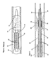
- FIG. 1 is an elevational view of a distal end of a previously known stent deployment catheter.
- FIG. 2 is a cross-sectional view of a distal end of a stent deployment system constructed in accordance with the present invention.
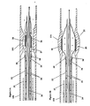
- FIGS. 3A and 3B show cross-sectional views, respectively, prior to and during deployment, of the distal end of a stent deployment system according to the present invention.
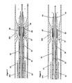
- FIG. 4 is a cross-sectional view of a distal end of an alternative embodiment of a stent deployment system according to the present invention.
- FIG. 5 is a cross-sectional view of a distal end of another alternative embodiment of a stent deployment system according to the present invention.
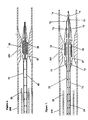
- FIG. 6 is a cross-sectional view of a distal end of a single-lumen embodiment of a stent deployment system according to the present invention.
- FIG. 7 is a cross-sectionaL view of the distal end of an alternative single-lumen embodiment of a stent deployment system according to the present invention.
- the present invention relates generally to methods and apparatus for deploying stents made of shape-memory material.
- a phase-change stent may be crimped or encapsulated onto the balloon of a balloon catheter. Encapsulation of the stent may be accomplished as described in U.S. Patent Application Serial No. 08/451,270, filed on May 30, 1995, which is hereby incorporated by reference.
- a stent delivery system including a balloon catheter having an inflation lumen in fluid communication with one or more perfusion apertures. Temperature-controlled fluid introduced into the inflation lumen serves both to pressurize and expand the balloon and also escape via the perfusion apertures to bathe the stent.
- Temperature-controlled fluid introduced into the inflation lumen serves both to pressurize and expand the balloon and also escape via the perfusion apertures to bathe the stent.
- This arrangement allows for the temperature of the stent to be controlled by the exiting fluid, while the inflating balloon maintains contact with the expanding stent.
- the balloon therefore assists in controlling the location of the stent during deployment and may also assist in its expansion in a conventional manner.
- Coil stent 15 is shown compressed onto guide catheter 16.
- Guide catheter 16 has perfusion apertures 12 which enable heated saline to be directed over the stent to effect the phase change and expansion.
- coil stent 15 expands out of contact with guide catheter 16.
- Holes 13 allow the heated saline to inflate distally-located balloon 14 to reduce thermodilution of the heated saline from the vicinity of the stent.
- Stent 28 illustratively forms a coil of shape-memory material, for example, Nitinol, positioned over balloon 27 of balloon catheter 22 in a stent engagement region.
- Shape-memory materials can also be used to form other stent configurations, such as tubular stents, without departing from the present invention.
- Balloon catheter 22 may be formed of conventional catheter materials and includes two lumens, central lumen 26 for receiving guidewire 24 and inflation lumen 25 for supplying temperature-controlled fluid to balloon 27.
- Balloon catheter 22 is delivered over guidewire 24, through guide catheter 23, to stenosis 101 in vessel 100 using conventional catheterization techniques.
- temperature-controlled fluid is introduced through inflation lumen 25 to balloon 27 as shown by the arrows in FIG. 2.
- This fluid which may be heated saline, pressurizes balloon 27 pushing it into intimate physical and thermal contact with stent 28.
- Stent 28 under the influence of the pressure and temperature from balloon 27, expands to its deployed form. Balloon 27 and stent 28 therefore remain in intimate contact at all times during this deployment, enabling accurate placement of stent 28.
- a plurality of apertures 29 are formed between the interior of balloon 27 and central lumen 26 distally of the stent location. These apertures are dimensioned to allow controlled leakage of the temperature-controlled fluid into central lumen 26, and thence into vessel 100, to maintain the temperature of the fluid in the balloon. Apertures 29 have sufficient size, for example, about 10 mils, and number that balloon 27 is sufficiently pressurized to be maintained in intimate contact with stent 28 during deployment.
- FIGS. 3A and 3B an alternative embodiment of the stent delivery system of the present invention is described. Elements common with FIG. 2 are indicated by like reference numerals in FIGS. 3A and 3B.
- stent 28 is compressed onto balloon 27 of balloon catheter 22.
- Balloon catheter 22 includes perfusion jets 30 located proximally of the stent position, by which temperature-controlled fluid may exit balloon catheter 22 and bathe the stent.
- Perfusion jets 30 direct temperature-controlled fluid from inflation lumen 25 over stent 28. This provides a second means effecting the phase change in stent 28 in addition to heat exchange with balloon 27, as in the embodiment of FIG. 2. Perfusion jets 30 also may be used as an alternative to, or in addition to, distally-located apertures 29 described with respect to the embodiment of FIG. 2. Perfusion jets 30 are provided in sufficient number and size, for example, having a diameter of 10 mils, to enable balloon 27 to be adequately pressurized.
- FIG. 3B illustrates operation of the delivery system and stent 28 during deployment.
- balloon 27 maintains intimate contact with stent 28 during deployment, thereby providing both temperature control and accurate placement of stent 28.
- Balloon 27 may additionally assist in the expansion of the stent by the application of radial expansion pressure to the stent.
- balloon 27 has a plurality of perfusion pores 40 located in the stent engagement region of the balloon.
- Perfusion pores 40 permit seepage of temperature-controlled fluid through the wall of balloon 27 directly onto stent 28.
- Perfusion pores 40 may be macroscopic or microscopic apertures, depending upon the choice of material for the balloon, and are preferably evenly distributed over the area within which the stent is located. As with the embodiments of FIGS. 2 and 3, the size and number of perfusion pores 40 is selected so that adequate pressure may be maintained in balloon 27 during deployment of stent 28.
- FIG. 5 illustrates yet another alternative embodiment of the stent delivery system of the present invention.
- balloon catheter 22 includes external apertures 50 located distally of the stent location. Apertures 50 may be provided through balloon 27 or may be in the form of a partial seal between balloon 27 and central lumen 26.
- temperature-controlled fluid leaks out of the balloon in a controlled manner downstream of stent 28. The fluid in the balloon is continually replenished through inflation lumen 25, thus maintaining the pressure and temperature of the fluid in balloon 27.
- balloon catheter 22 includes a single lumen 60.
- the absence of a guidewire and central lumen 26 allows for a significant reduction in the diameter of the stent delivery system.
- balloon catheter 22 does not permit use of a guidewire, the catheter must itself be steerable. This can be acheived using the conventional technology of fixed-wire stents.
- Balloon catheter 22 of FIG. 6 includes perfusion pores 40 in balloon 27 in the stent engagement region. Perfusion pores 40 allow temperature-controlled fluid to bathe stent 28, as shown by the arrows in FIG. 6. Like the previously described embodiments, balloon 27 is maintained in intimate physical and thermal contact with stent 28 during deployment, thus assisting deployment and positioning of the stent.
- Balloon catheter 22 includes inflation lumen 71 that communicates with the interior of balloon 27 via apertures 72.
- Inflation lumen 71 is also adapted to receive guidewire 24.
- a taper 73 is provided in the distal end of the catheter so that inflation lumen 71 is only slightly larger than guidewire 24. The small remaining gap between the guidewire and the exterior of inflation lumen 71 forms aperture 74.
- Aperture 74 permits escape of temperature-controlled fluid from the balloon as shown by the arrows.
- Temperature-controlled fluid flows through apertures 72 into balloon 27, as shown by the arrows in FIG. 7, to control the balloon temperature and pressurize the balloon during stent deployment.
- Apertures 72 are of sufficient number and size so as to ensure adequate pressurization of the balloon to maintain contact with the stent and also adequate flow through the balloon to maintain the temperature of the fluid.
- a deployed stent comprising a two-way shape-memory material or a mechanically expanded stent having a shape memory of a reduced diameter may be retrieved using the above-described apparatus.
- a stent comprising a two-way shape-memory material changes from its contracted configuration to its expanded configuration, and vice-versa, when it experiences a phase change.
- the retrieval process begins by positioning the deployment device inside of the lumen of an expanded stent.
- a fluid at a temperature selected to cause the phase-change material of the stent to contract is then introduced to the balloon, which expands to contact the deployed stent and to place the fluid in thermal contact with the stent.
- the stent changes phase, it contracts onto the balloon, and when the phase change is completed, perfusion may be halted.
- the balloon is then deflated and the delivery system withdrawn to retrieve the stent.
- the present invention may also be used for treatment of narrowed vessels in other components of the vascular system, for example, the kidney, leg, carotid artery, or elsewhere in the body.
- the size of the stent and the stent delivery system, as well as their external characteristics, may need to be adjusted to compensate for the differing sizes of the vessel or passageway to be treated.
- FIGS. 2-7 are for illustrative purposes only.
- a typical catheter according to the present invention would have a combination of such apertures designed so as to optimize the temperature environment of the stent through the combination of contact with the balloon and direct contact with the perfusing temperature-controlled fluid.
- this invention can be used for the deployment and retrieval of shape-memory stents of many different configurations. Accordingly, the scope of this invention is to be limited only by the appended claims.
Abstract
Description
- This invention relates to methods and apparatus for delivering, deploying and retrieving medical endoprostheses, commonly referred to as "stents". More specifically, the invention relates to delivering a stent composed of shape-memory material on a balloon catheter without using an outer protective sheath, and deploying the stent by introducing temperature-controlled fluid through the balloon catheter to induce a shape change in the shape-memory material, the fluid causing the balloon to expand along with the stent thereby enhancing control over placement of the stent and enabling retrieval of the stent when necessary.
- Stents are known in the prior art for maintaining the patency of a diseased or weakened vessel or other passageway. Stents have been implanted, for example, in passageways in the urinary tract system and in the coronary arteries of the endovascular system. Such mechanical prosthetic devices are typically inserted into the vessel, positioned across an affected area and then expanded, or allowed to self-expand, to keep the vessel or passageway open. Effectively, the stent overcomes the natural tendency of the weakened area to close. Stents used in the vascular system are generally implanted transluminally during or following percutaneous transluminal coronary angioplasty (angioplasty or PCTA).
- A number of vascular stents have been proposed, including self-expanding stents and expandable stents. Self-expanding stents may be mechanically compressed springs which expand when released, and/or they may be constructed from shape-memory materials including shape-memory polymers and metals such as nickel-titanium ("Nitinol") alloys and the like, which have shape-memory characteristics.
- In a manner known in the art, a stent formed of shape-memory alloy such as nickel-titanium is formed into a desired expanded configuration and then heated until the metal crystals assume their high-temperature structure known as the beta phase, parent phase or austenite. The stent is then cooled so that the crystals transition to a martensite crystal structure, generally with no change in shape. The material is then formed into a reduced diameter configuration for implantation.
- When the temperature of the stent is later raised so that the crystal structure transitions to the parent phase, the shape of the stent returns to the desired expanded configuration. Typically, a material having a phase-change transition temperature in excess of 125°F is chosen to prevent premature expansion of the stent upon exposure to human body temperature (97.8°F). However, materials with lower phase-change transition temperatures may be used, provided the stent is insulated from the human body temperature prior to reaching the location for deployment.
- Dotter U.S. Patent No. 4,503,569 describes a stent comprising a helically wound coil of shape-memory alloy that is placed over the outer wall of a guide catheter. The stent and guide catheter are carried within an outer sheath. At the delivery site, the outer sheath is withdrawn. A hot saline solution is then injected through the inner guide catheter and flows out of the catheter through apertures, so that the fluid bathes the stent and causes it to expand. The patent describes that a balloon may be positioned on one or both sides of the stent to reduce thermodilution of the saline solution and enhance the phase change.
- Balko et al. U.S. Patent No. 4,512,338 which discloses a Nitinol wire stent in the form of a coil which is delivered to the desired site while housed inside of an insulating sheath. When the insulating sheath is withdrawn, the surrounding body temperature causes the stent to expand.
- Froix U.S. Patent No. 5,163,952 discloses shape-memory-polymer tubular and coil stents having an elastic memory which causes them to expand to a predetermined diameter upon exposure to particular conditions. Shape-memory polymer stents are initially formed having the desired expanded diameter. The stents are then physically stretched at elevated temperature causing them to assume a reduced diameter. While under tension, the stents are cooled to below the glass transition phase of the plastic. The stent then remains in the stretched and reduced-diameter configuration until after the stent is raised to above the glass transition temperature at the site desired to be treated. Depending upon the polymer selected and process of manufacture, stents can be formed to expand by different degrees and upon exposure to various conditions including various temperatures.
- Various methods have been used to induce the temperature change required to effect the shape-memory characteristic, including intervascular electrical resistive heating elements, R.F., and temperature-controlled fluid boluses injected through a guide catheter around the delivery catheter.
- A drawback of previously known delivery systems for shape-memory material stents is the use of a protective sheath to prevent premature expansion at body temperatures and to enhance delivery through the tortuous vessels of the vascular system. Such sheaths increase the cross-sectional profile of the delivery system, necessitating use of a delivery catheter with a larger diameter. The large diameter of the delivery catheter may in turn increase the risk of complications at the patient access site.
- The increased cross-sectional profile of the delivery system also detracts from the ability of the device to navigate through tortuous vessels or passageways. The increased cross-sectional profile of the delivery system may make it impossible to deliver a phase-change material stent to the area desired to be treated and may decrease the ability to deliver sufficient contrast material through the guide catheter for enabling precise positioning.
- Another drawback of self-expanding stents, both coiled spring stents and phase-change stents, is the inability to control expansion of the stent once the stent loses contact with the guide catheter. In particular, as the stent expands, or is pushed out of a catheter for self-expansion, it moves radially out of contact with the delivery device. Because there no longer is contact between the stent and the delivery device, there is no mechanism to control positioning of the stent location during this critical phase of deployment. Consequently, the stent may move away from the desired site.
- Yet another problem is encountered when elevated (or reduced) temperatures are required to cause the phase change in the stent material. For example, in the system described in the Dotter patent, the fluid flowing through the catheter exchanges heat with the vessel wall, and as the fluid flows out of the catheter it is diluted by the blood or other fluids contained in the vessel. Thus, it may be necessary to flush large volumes of liquid through the guide catheter to maintain the required temperature environment around the stent to effect deployment. The injection of such large volumes of hot or cold fluid into the vessel may be injurious or hazardous to the vessel and the tissues through which it passes.
- It would therefore be desirable to provide methods and apparatus for delivering a shape-memory material stent to an affected area of a vessel without using a sheath.
- It would further be desirable to provide methods and apparatus for effecting the phase change of the stent without perfusing large quantities of fluid into the vessel to be treated.
- It would still further be desirable to provide methods and apparatus for maintaining control over the positioning of a phase-change stent during deployment.
- It is an object of this invention to provide methods and apparatus for delivering a phase-change stent to an affected area of a vessel without using a sheath.
- It is a further an object of this invention to provide methods and apparatus for effecting the phase change of the stent without perfusing large quantities of fluid into the vessel to be treated.
- It is still further an object of this invention to provide methods and apparatus for maintaining control over the positioning of a phase-change stent during deployment.
- These and other objects of the invention are accomplished in accordance with the principles of the invention by providing a phase-change stent crimped or encapsulated onto the balloon of a balloon catheter having perfusion apertures communicating from the inflation lumen to the exterior of the catheter to enable a temperature-controlled fluid to be used both to pressurize the balloon and induce expansion of the stent. Some of the intended uses for a delivery system in accordance with the present invention include PTCA type stenting, PTA type stenting, graft support, graft delivery, INR use, GI tract use, drug delivery, and biliary stenting.
- The following is a description of some specific embodiments of the invention, reference being made to the accompanying drawings, in which:
- FIG. 1 is an elevational view of a distal end of a previously known stent deployment catheter.
- FIG. 2 is a cross-sectional view of a distal end of a stent deployment system constructed in accordance with the present invention.
- FIGS. 3A and 3B show cross-sectional views, respectively, prior to and during deployment, of the distal end of a stent deployment system according to the present invention.
- FIG. 4 is a cross-sectional view of a distal end of an alternative embodiment of a stent deployment system according to the present invention.
- FIG. 5 is a cross-sectional view of a distal end of another alternative embodiment of a stent deployment system according to the present invention.
- FIG. 6 is a cross-sectional view of a distal end of a single-lumen embodiment of a stent deployment system according to the present invention.
- FIG. 7 is a cross-sectionaL view of the distal end of an alternative single-lumen embodiment of a stent deployment system according to the present invention.
- The present invention relates generally to methods and apparatus for deploying stents made of shape-memory material. In particular, according to the present invention, a phase-change stent may be crimped or encapsulated onto the balloon of a balloon catheter. Encapsulation of the stent may be accomplished as described in U.S. Patent Application Serial No. 08/451,270, filed on May 30, 1995, which is hereby incorporated by reference.
- In accordance with the present invention, a stent delivery system is provided including a balloon catheter having an inflation lumen in fluid communication with one or more perfusion apertures. Temperature-controlled fluid introduced into the inflation lumen serves both to pressurize and expand the balloon and also escape via the perfusion apertures to bathe the stent. This arrangement allows for the temperature of the stent to be controlled by the exiting fluid, while the inflating balloon maintains contact with the expanding stent. The balloon therefore assists in controlling the location of the stent during deployment and may also assist in its expansion in a conventional manner.
- Referring to FIG. 1, an illustrative prior art stent deployment system, such as disclosed in the above-mentioned Dotter patent, is described.
Coil stent 15 is shown compressed ontoguide catheter 16.Guide catheter 16 hasperfusion apertures 12 which enable heated saline to be directed over the stent to effect the phase change and expansion. During and after this deployment,coil stent 15 expands out of contact withguide catheter 16.Holes 13 allow the heated saline to inflate distally-locatedballoon 14 to reduce thermodilution of the heated saline from the vicinity of the stent. - Referring now to FIG. 2, an illustrative embodiment of a stent delivery system of the present invention is described.
Stent 28 illustratively forms a coil of shape-memory material, for example, Nitinol, positioned overballoon 27 ofballoon catheter 22 in a stent engagement region. Shape-memory materials can also be used to form other stent configurations, such as tubular stents, without departing from the present invention.Balloon catheter 22 may be formed of conventional catheter materials and includes two lumens,central lumen 26 for receivingguidewire 24 andinflation lumen 25 for supplying temperature-controlled fluid to balloon 27. -
Balloon catheter 22 is delivered overguidewire 24, throughguide catheter 23, to stenosis 101 invessel 100 using conventional catheterization techniques. When located at the site ofstenosis 101, temperature-controlled fluid is introduced throughinflation lumen 25 to balloon 27 as shown by the arrows in FIG. 2. This fluid, which may be heated saline, pressurizesballoon 27 pushing it into intimate physical and thermal contact withstent 28.Stent 28, under the influence of the pressure and temperature fromballoon 27, expands to its deployed form.Balloon 27 andstent 28 therefore remain in intimate contact at all times during this deployment, enabling accurate placement ofstent 28. - As seen in FIG. 2, a plurality of
apertures 29 are formed between the interior ofballoon 27 andcentral lumen 26 distally of the stent location. These apertures are dimensioned to allow controlled leakage of the temperature-controlled fluid intocentral lumen 26, and thence intovessel 100, to maintain the temperature of the fluid in the balloon.Apertures 29 have sufficient size, for example, about 10 mils, and number thatballoon 27 is sufficiently pressurized to be maintained in intimate contact withstent 28 during deployment. - With respect to FIGS. 3A and 3B, an alternative embodiment of the stent delivery system of the present invention is described. Elements common with FIG. 2 are indicated by like reference numerals in FIGS. 3A and 3B. In FIG. 3A,
stent 28 is compressed ontoballoon 27 ofballoon catheter 22.Balloon catheter 22 includesperfusion jets 30 located proximally of the stent position, by which temperature-controlled fluid may exitballoon catheter 22 and bathe the stent. -
Perfusion jets 30 direct temperature-controlled fluid frominflation lumen 25 overstent 28. This provides a second means effecting the phase change instent 28 in addition to heat exchange withballoon 27, as in the embodiment of FIG. 2.Perfusion jets 30 also may be used as an alternative to, or in addition to, distally-locatedapertures 29 described with respect to the embodiment of FIG. 2.Perfusion jets 30 are provided in sufficient number and size, for example, having a diameter of 10 mils, to enableballoon 27 to be adequately pressurized. - FIG. 3B illustrates operation of the delivery system and
stent 28 during deployment. As seen in FIG. 3B,balloon 27 maintains intimate contact withstent 28 during deployment, thereby providing both temperature control and accurate placement ofstent 28.Balloon 27 may additionally assist in the expansion of the stent by the application of radial expansion pressure to the stent. - Referring now to FIG. 4, another alternative embodiment of the present invention is described in which
balloon 27 has a plurality of perfusion pores 40 located in the stent engagement region of the balloon. Perfusion pores 40 permit seepage of temperature-controlled fluid through the wall ofballoon 27 directly ontostent 28. Perfusion pores 40 may be macroscopic or microscopic apertures, depending upon the choice of material for the balloon, and are preferably evenly distributed over the area within which the stent is located. As with the embodiments of FIGS. 2 and 3, the size and number of perfusion pores 40 is selected so that adequate pressure may be maintained inballoon 27 during deployment ofstent 28. - FIG. 5 illustrates yet another alternative embodiment of the stent delivery system of the present invention. In the embodiment of FIG. 5,
balloon catheter 22 includesexternal apertures 50 located distally of the stent location.Apertures 50 may be provided throughballoon 27 or may be in the form of a partial seal betweenballoon 27 andcentral lumen 26. In this embodiment, temperature-controlled fluid leaks out of the balloon in a controlled manner downstream ofstent 28. The fluid in the balloon is continually replenished throughinflation lumen 25, thus maintaining the pressure and temperature of the fluid inballoon 27. - With respect to FIG. 6, a single lumen embodiment of the present invention is described. As seen in FIG. 6,
balloon catheter 22 includes asingle lumen 60. The absence of a guidewire andcentral lumen 26 allows for a significant reduction in the diameter of the stent delivery system. However, becauseballoon catheter 22 does not permit use of a guidewire, the catheter must itself be steerable. This can be acheived using the conventional technology of fixed-wire stents. -
Balloon catheter 22 of FIG. 6 includes perfusion pores 40 inballoon 27 in the stent engagement region. Perfusion pores 40 allow temperature-controlled fluid to bathestent 28, as shown by the arrows in FIG. 6. Like the previously described embodiments,balloon 27 is maintained in intimate physical and thermal contact withstent 28 during deployment, thus assisting deployment and positioning of the stent. - Referring now to FIG. 7, an alternative embodiment of a single lumen delivery system is described.
Balloon catheter 22 includesinflation lumen 71 that communicates with the interior ofballoon 27 viaapertures 72.Inflation lumen 71 is also adapted to receiveguidewire 24. Ataper 73 is provided in the distal end of the catheter so thatinflation lumen 71 is only slightly larger thanguidewire 24. The small remaining gap between the guidewire and the exterior ofinflation lumen 71forms aperture 74.Aperture 74 permits escape of temperature-controlled fluid from the balloon as shown by the arrows. - Temperature-controlled fluid flows through
apertures 72 intoballoon 27, as shown by the arrows in FIG. 7, to control the balloon temperature and pressurize the balloon during stent deployment.Apertures 72 are of sufficient number and size so as to ensure adequate pressurization of the balloon to maintain contact with the stent and also adequate flow through the balloon to maintain the temperature of the fluid. - Further in accordance with the above-described methods and apparatus, a deployed stent comprising a two-way shape-memory material or a mechanically expanded stent having a shape memory of a reduced diameter may be retrieved using the above-described apparatus. A stent comprising a two-way shape-memory material changes from its contracted configuration to its expanded configuration, and vice-versa, when it experiences a phase change.
- The retrieval process begins by positioning the deployment device inside of the lumen of an expanded stent. A fluid at a temperature selected to cause the phase-change material of the stent to contract is then introduced to the balloon, which expands to contact the deployed stent and to place the fluid in thermal contact with the stent. As the stent changes phase, it contracts onto the balloon, and when the phase change is completed, perfusion may be halted. The balloon is then deflated and the delivery system withdrawn to retrieve the stent.
- While one application for the above-described stent includes treatment of cardiovascular disease such as atherosclerosis or other forms of coronary narrowing, the present invention may also be used for treatment of narrowed vessels in other components of the vascular system, for example, the kidney, leg, carotid artery, or elsewhere in the body. As will of course be appreciated, the size of the stent and the stent delivery system, as well as their external characteristics, may need to be adjusted to compensate for the differing sizes of the vessel or passageway to be treated.
- While this invention has been described in connection with illustrative preferred embodiments thereof, modifications and changes may be made thereto by those skilled in the art without departing from the spirit and scope of the invention. In particular, the location of the various apertures shown in FIGS. 2-7 are for illustrative purposes only. A typical catheter according to the present invention would have a combination of such apertures designed so as to optimize the temperature environment of the stent through the combination of contact with the balloon and direct contact with the perfusing temperature-controlled fluid. Moreover, this invention can be used for the deployment and retrieval of shape-memory stents of many different configurations. Accordingly, the scope of this invention is to be limited only by the appended claims.
Claims (31)
- A catheter for use in delivering a stent, the stent having a reduced diameter for intraluminal delivery and an expanded diameter, greater than the reduced diameter, when heated beyond a transition temperature, the catheter comprising:a first tube having a proximal end, a distal end and a wall defining a first lumen;a balloon sealingly connected to the first tube adjacent the distal end, the balloon defining an interior volume and having an exterior surface defining a stent engagement region, the interior volume of the balloon in communication with the first lumen, so that a heated fluid introduced through the proximal end of the first lumen pressurizes the balloon and heats the stent engagement region.
- The catheter as defined in claim 1 wherein the exterior surface of the balloon further comprises a portion defining a plurality of perfusion pores in the stent engagement region.
- The catheter as defined in claim 2 wherein the first tube further includes a portion defining at least one aperture through the wall, the interior volume of the balloon communicating with the first lumen via the at least one aperture.
- The catheter as defined in claim 1 wherein the first tube further comprises a portion defining an exit port located distally of the balloon.
- The catheter as defined in claim 4 wherein the first tube further includes a portion defining at least one aperture through the wall, the interior volume of the balloon communicating with the first lumen via the at least one aperture.
- The catheter as defined in claim 5 wherein the first lumen is adapted to receive a guidewire, the guidewire extending from the catheter distally of the balloon via the exit port.
- The catheter as defined in claim 1 further comprising a second tube defining a second lumen adapted for receiving a guidewire, the first tube further including a portion defining at least one aperture through the wall located proximally of the stent engagement region.
- The catheter as defined in claim 7 wherein the second tube is disposed concentrically within the first tube, the first lumen being defined by an annulus between the first and second tubes.
- The catheter as defined in claim 1 further comprising a second tube defining a second lumen adapted for receiving a guidewire, the balloon including a portion defining at least one aperture located distally of the stent engagement region.
- The catheter as defined in claim 9 wherein the second tube is disposed concentrically within the first tube, the first lumen being defined by an annulus between the first and second tubes.
- The catheter as defined in claim 1 further comprising a second tube defining a second lumen adapted for receiving a guidewire, the balloon including a portion defining at least one aperture located distally of the stent engagement region.
- The catheter as defined in claim 11 wherein the second tube is disposed concentrically within the first tube, the first lumen being defined by an annulus between the first and second tubes.
- The catheter as defined in claim 1 further comprising a second tube defining a second lumen adapted for receiving a guidewire, the balloon including a portion defining a plurality of perfusion pores located in the stent engagement region.
- The catheter as defined in claim 13 wherein the second tube is disposed concentrically within the first tube, the first lumen being defined by an annulus between the first and second tubes.
- A method for manufacturing a stent delivery system including a catheter and a stent formed of a shape-memory material, the method comprising steps of:providing a catheter having proximal and distal ends and an inflation lumen;providing a balloon at the distal end of the catheter so that the interior of the balloon is in fluid communication with the inflation lumen, the balloon having a portion defining a stent engagement region;providing at least one aperture in fluid communication with the inflation lumen to permit temperature-controlled fluid to exit the catheter near the balloon;forming a stent having an expanded diameter from a shape-memory material;heating the stent until the shape-memory material transitions to an austenite phase,cooling the stent until the shape-memory material transitions to a martensite phase;positioning the stent over the stent engagement region of the balloon; andcompressing the stent onto the stent engagement region to a reduced diameter less than the expanded diameter.
- The method as defined in claim 15 wherein the step of providing at least one aperture in fluid communication with the inflation lumen comprises a step of providing one or more perfusion jets located on the catheter proximal to the balloon, the jets being adapted to direct temperature-controlled fluid over the stent.
- The method as defined in claim 15 wherein the step of providing at least one aperture in fluid communication with the inflation lumen comprises a step of providing one or more perfusion pores located in the stent engagement region, the perfusion pores being adapted to allow a controlled perfusion of temperature-controlled fluid over the stent.
- The method as defined in claim 15 wherein the step of providing at least one aperture in fluid communication with the inflation lumen comprises a step of providing one or more apertures located on the catheter distal to the balloon, the apertures being adapted to allow a controlled flow of temperature-controlled fluid out of the balloon.
- The method as defined in claim 17 wherein the step of providing at least one aperture in fluid communication with the inflation lumen further comprises providing at least one aperture located distal to the stent engagement region of the balloon and adapted to allow a controlled flow of temperature-controlled fluid out of the balloon.
- The method as defined in claim 15 wherein the step of providing at least one aperture in fluid communication with the inflation lumen comprises a step of providing at least one aperture located between the interior of the balloon and the interior of a central lumen passing through the balloon, the at least one aperture being adapted to allow a controlled flow of temperature-controlled fluid out of the balloon.
- The method as defined in claim 15 wherein the step of providing at least one aperture in fluid communication with the inflation lumen comprises a step of providing at least one aperture located between the interior of the balloon and the exterior of the balloon distal of the stent engagement region, the at least one downstream aperture being adapted to allow a controlled flow of temperature-controlled fluid out of the balloon.
- A method for manufacturing a stent delivery system including a catheter and a stent formed of a shape-memory material, the method comprising steps of:providing a catheter having proximal and distal ends and an inflation lumen;providing a balloon at the distal end of the catheter so that the interior of the balloon is in fluid communication with the inflation lumen, the balloon having a portion defining a stent engagement region;providing at least one aperture in fluid communication with the inflation lumen to permit temperature-controlled fluid to exit the catheter near the balloon;forming a stent having an expanded diameter from a shape-memory polymer;physically reducing the diameter of the stent;cooling the stent until the polymer enters the glass phase;positioning the stent over the stent engagement region of the balloon.
- The method as defined in claim 22 wherein the step of providing at least one aperture in fluid communication with the inflation lumen comprises a step of providing one or more perfusion jets located on the catheter proximal to the balloon, the jets being adapted to direct temperature-controlled fluid over the stent.
- The method as defined in claim 22 wherein the step of providing at least one aperture in fluid communication with the inflation lumen comprises a step of providing one or more perfusion pores located in the stent engagement region, the perfusion pores being adapted to allow a controlled perfusion of temperature-controlled fluid over the stent.
- The method as defined in claim 22 wherein the step of providing at least one aperture in fluid communication with the inflation lumen comprises a step of providing one or more apertures located on the catheter distal to the balloon, the apertures being adapted to allow a controlled flow of temperature-controlled fluid out of the balloon.
- The method as defined in claim 24 wherein the step of providing at least one aperture in fluid communication with the inflation lumen further comprises providing at least one aperture located distal to the stent engagement region of the balloon and adapted to allow a controlled flow of temperature-controlled fluid out of the balloon.
- The method as defined in claim 22 wherein the step of providing at least one aperture in fluid communication with the inflation lumen comprises a step of providing at least one aperture located between the interior of the balloon and the interior of a central lumen passing through the balloon, the at least one aperture being adapted to allow a controlled flow of temperature-controlled fluid out of the balloon.
- The method as defined in claim 22 wherein the step of providing at least one aperture in fluid communication with the inflation lumen comprises a step of providing at least one aperture located between the interior of the balloon and the exterior of the balloon distal of the stent engagement region, the at least one downstream aperture being adapted to allow a controlled flow of temperature-controlled fluid out of the balloon.
- A method for introducing and deploying a stent comprising a shape-memory material at an affected site within a vessel of a human body, the method comprising steps of:providing a catheter having proximal and distal ends, a balloon located in the region of the distal end, an inflation lumen communicating between the proximal end and the balloon, and at least one aperture in fluid communication with the inflation lumen to permit temperature-controlled fluid to exit the catheter near the balloon;providing a stent that expands to an expanded diameter when heated beyond a transition temperature;positioning the stent over the balloon in a form having a reduced diameter, the reduced diameter being less than the expanded diameter;inserting the catheter transluminally through a body vessel until the stent is located within an area of the vessel to be treated;providing a bio-compatible fluid at a temperature sufficient to heat the stent above the transition temperature; andinjecting the biocompatible fluid into the inflation lumen of the catheter at the proximal end of the catheter to cause inflation of the balloon and a controlled flow of the biocompatible fluid through the at least one aperture, the bio-compatible fluid injected at a rate sufficient to maintain the balloon and the stent in intimate physical and thermal contact during transition of the stent from the reduced diameter to the expanded diameter.
- The method as defined in claim 29 further comprising steps of:after the step of injecting bio-compatible fluid, dissipating the fluid in the balloon to cause deflation of the balloon; andwithdrawing the catheter from the vessel of the human body.
- A method for retrieving a stent having an expanded diameter comprising a shape-memory material from an affected site within a vessel of a human body, the method comprising steps of:providing a catheter having proximal and distal ends, a balloon located in the region of the distal end, an inflation lumen communicating between the proximal end and the balloon, and at least one aperture in fluid communication with the inflation lumen to permit temperature-controlled fluid to exit the catheter near the balloon;inserting the catheter transluminally through a body vessel until the balloon is located within the stent within the body vessel;providing a bio-compatible fluid at a temperature effective to cause the stent to contract from the expanded diameter to a reduced diameter less than the expanded diameter;injecting the biocompatible fluid into the inflation lumen of the catheter at the proximal end of the catheter to cause inflation of the balloon and a controlled flow of the biocompatible fluid through the at least one aperture, the bio-compatible fluid injected at a rate sufficient to inflate the balloon into intimate physical and thermal contact with the stent while the stent contracts from the expanded diameter to the reduced diameter;dissipating the fluid in the balloon to allow deflation of the balloon as the stent contracts onto the balloon; andwithdrawing the catheter and the stent from the vessel of the human body.
Applications Claiming Priority (2)
| Application Number | Priority Date | Filing Date | Title |
|---|---|---|---|
| US568543 | 1995-12-07 | ||
| US08/568,543 US6579305B1 (en) | 1995-12-07 | 1995-12-07 | Method and apparatus for delivery deployment and retrieval of a stent comprising shape-memory material |
Publications (3)
| Publication Number | Publication Date |
|---|---|
| EP0778010A2 true EP0778010A2 (en) | 1997-06-11 |
| EP0778010A3 EP0778010A3 (en) | 1997-07-16 |
| EP0778010B1 EP0778010B1 (en) | 2003-09-17 |
Family
ID=24271717
Family Applications (1)
| Application Number | Title | Priority Date | Filing Date |
|---|---|---|---|
| EP96308844A Expired - Lifetime EP0778010B1 (en) | 1995-12-07 | 1996-12-05 | Apparatus for delivery, deployment and retrieval of stents |
Country Status (7)
| Country | Link |
|---|---|
| US (1) | US6579305B1 (en) |
| EP (1) | EP0778010B1 (en) |
| JP (2) | JPH09266950A (en) |
| AT (1) | ATE249794T1 (en) |
| AU (1) | AU716432B2 (en) |
| CA (1) | CA2190795C (en) |
| DE (1) | DE69630002T2 (en) |
Cited By (12)
| Publication number | Priority date | Publication date | Assignee | Title |
|---|---|---|---|---|
| WO1999015106A1 (en) * | 1997-09-22 | 1999-04-01 | Ave Connaught | Balloon mounted stent and method therefor |
| EP0974313A1 (en) * | 1998-07-23 | 2000-01-26 | Jomed Implantate GmbH | Stent implantation catheter assembly |
| EP1000591A3 (en) * | 1998-11-16 | 2000-06-07 | Cordis Corporation | Balloon catheter and stent delivery system having enhanced stent retention |
| US6289568B1 (en) | 1998-11-16 | 2001-09-18 | Cordis Corporation | Method for making a balloon catheter stent deployment system |
| US6293959B1 (en) | 1998-11-16 | 2001-09-25 | Cordis Corporation | Balloon catheter and stent delivery system having enhanced stent retention and method |
| US6464718B1 (en) | 1998-11-16 | 2002-10-15 | Cordis Corporation | Balloon catheter for stent delivery having microchannels and method |
| US6562061B1 (en) | 2000-02-22 | 2003-05-13 | Scimed Life Systems, Inc. | Stent delivery balloon with securement structure |
| FR2839880A1 (en) * | 2002-05-21 | 2003-11-28 | Groupe Lepine | Connecting bar for intervertebral fixator used in spinal correction has duct for heat exchange fluid to actuate shape memory metal |
| US6676692B2 (en) | 2001-04-27 | 2004-01-13 | Intek Technology L.L.C. | Apparatus for delivering, repositioning and/or retrieving self-expanding stents |
| WO2005025457A1 (en) * | 2003-08-26 | 2005-03-24 | Boston Scientific Scimed, Inc. | Stent delivery system |
| WO2018026818A1 (en) * | 2016-08-02 | 2018-02-08 | Boston Scientific Scimed, Inc. | Stent delivery system |
| US9913649B2 (en) | 2014-05-28 | 2018-03-13 | Boston Scientific Scimed, Inc. | Catheter with radiofrequency cutting tip and heated balloon |
Families Citing this family (101)
| Publication number | Priority date | Publication date | Assignee | Title |
|---|---|---|---|---|
| US6530952B2 (en) * | 1997-12-29 | 2003-03-11 | The Cleveland Clinic Foundation | Bioprosthetic cardiovascular valve system |
| US6358276B1 (en) * | 1998-09-30 | 2002-03-19 | Impra, Inc. | Fluid containing endoluminal stent |
| DE19936980C1 (en) * | 1999-08-05 | 2001-04-26 | Aesculap Ag & Co Kg | Insertion catheter for vascular prostheses |
| US7572270B2 (en) | 2001-02-16 | 2009-08-11 | Cordis Corporation | Balloon catheter stent delivery system with ridges |
| DE60232710D1 (en) | 2001-02-16 | 2009-08-06 | Cordis Corp | METHOD FOR PRODUCING A BALLOON CATHETER STENT APPLICATION SYSTEM WITH FINISHING |
| US6666880B1 (en) * | 2001-06-19 | 2003-12-23 | Advised Cardiovascular Systems, Inc. | Method and system for securing a coated stent to a balloon catheter |
| GB0121980D0 (en) | 2001-09-11 | 2001-10-31 | Cathnet Science Holding As | Expandable stent |
| US6863683B2 (en) | 2001-09-19 | 2005-03-08 | Abbott Laboratoris Vascular Entities Limited | Cold-molding process for loading a stent onto a stent delivery system |
| US20030135266A1 (en) | 2001-12-03 | 2003-07-17 | Xtent, Inc. | Apparatus and methods for delivery of multiple distributed stents |
| US7892273B2 (en) | 2001-12-03 | 2011-02-22 | Xtent, Inc. | Custom length stent apparatus |
| US7182779B2 (en) | 2001-12-03 | 2007-02-27 | Xtent, Inc. | Apparatus and methods for positioning prostheses for deployment from a catheter |
| US20040186551A1 (en) | 2003-01-17 | 2004-09-23 | Xtent, Inc. | Multiple independent nested stent structures and methods for their preparation and deployment |
| US8080048B2 (en) * | 2001-12-03 | 2011-12-20 | Xtent, Inc. | Stent delivery for bifurcated vessels |
| US7294146B2 (en) | 2001-12-03 | 2007-11-13 | Xtent, Inc. | Apparatus and methods for delivery of variable length stents |
| US7147656B2 (en) | 2001-12-03 | 2006-12-12 | Xtent, Inc. | Apparatus and methods for delivery of braided prostheses |
| US7351255B2 (en) | 2001-12-03 | 2008-04-01 | Xtent, Inc. | Stent delivery apparatus and method |
| US7137993B2 (en) | 2001-12-03 | 2006-11-21 | Xtent, Inc. | Apparatus and methods for delivery of multiple distributed stents |
| US7309350B2 (en) | 2001-12-03 | 2007-12-18 | Xtent, Inc. | Apparatus and methods for deployment of vascular prostheses |
| US20030163190A1 (en) * | 2002-02-25 | 2003-08-28 | Scimed Life Systems, Inc. | High temperature stent delivery system |
| US20030195609A1 (en) * | 2002-04-10 | 2003-10-16 | Scimed Life Systems, Inc. | Hybrid stent |
| US6699275B1 (en) * | 2002-10-11 | 2004-03-02 | Enteromedics Inc. | Stent and delivery system |
| US20040193246A1 (en) * | 2003-03-25 | 2004-09-30 | Microvention, Inc. | Methods and apparatus for treating aneurysms and other vascular defects |
| GB0310715D0 (en) * | 2003-05-09 | 2003-06-11 | Angiomed Ag | Strain management in stent delivery system |
| US7241308B2 (en) | 2003-06-09 | 2007-07-10 | Xtent, Inc. | Stent deployment systems and methods |
| US20050010105A1 (en) * | 2003-07-01 | 2005-01-13 | Sra Jasbir S. | Method and system for Coronary arterial intervention |
| WO2005037133A2 (en) * | 2003-10-10 | 2005-04-28 | Arshad Quadri | System and method for endoluminal grafting of bifurcated and branched vessels |
| US20050137620A1 (en) * | 2003-12-22 | 2005-06-23 | Scimed Life Systems, Inc. | Balloon catheter retrieval device |
| US7326236B2 (en) | 2003-12-23 | 2008-02-05 | Xtent, Inc. | Devices and methods for controlling and indicating the length of an interventional element |
| US7323006B2 (en) * | 2004-03-30 | 2008-01-29 | Xtent, Inc. | Rapid exchange interventional devices and methods |
| US20050267570A1 (en) * | 2004-05-27 | 2005-12-01 | Shadduck John H | Endovascular occlusion devices and methods of use |
| US20050288766A1 (en) | 2004-06-28 | 2005-12-29 | Xtent, Inc. | Devices and methods for controlling expandable prostheses during deployment |
| US8317859B2 (en) | 2004-06-28 | 2012-11-27 | J.W. Medical Systems Ltd. | Devices and methods for controlling expandable prostheses during deployment |
| EP1788988A4 (en) * | 2004-07-27 | 2011-05-11 | Univ Southern California | Percutaneously retrievable stent assembly with fluid draining capability |
| US7758640B2 (en) * | 2004-12-16 | 2010-07-20 | Valvexchange Inc. | Cardiovascular valve assembly |
| US8641746B2 (en) * | 2005-05-31 | 2014-02-04 | J.W. Medical Systems Ltd. | In situ stent formation |
| US7780723B2 (en) | 2005-06-13 | 2010-08-24 | Edwards Lifesciences Corporation | Heart valve delivery system |
| US8038704B2 (en) | 2005-07-27 | 2011-10-18 | Paul S. Sherburne | Stent and other objects removal from a body |
| WO2007022496A2 (en) * | 2005-08-19 | 2007-02-22 | Icon Medical Corp. | Medical device deployment instrument |
| CN100408122C (en) * | 2005-11-02 | 2008-08-06 | 陈鹏宏 | Device for posting prostate bracket made from nickel titanium |
| AU2007227000A1 (en) | 2006-03-20 | 2007-09-27 | Xtent, Inc. | Apparatus and methods for deployment of linked prosthetic segments |
| US8333000B2 (en) | 2006-06-19 | 2012-12-18 | Advanced Cardiovascular Systems, Inc. | Methods for improving stent retention on a balloon catheter |
| US20080004696A1 (en) * | 2006-06-29 | 2008-01-03 | Valvexchange Inc. | Cardiovascular valve assembly with resizable docking station |
| US7886419B2 (en) | 2006-07-18 | 2011-02-15 | Advanced Cardiovascular Systems, Inc. | Stent crimping apparatus and method |
| US20080269865A1 (en) * | 2006-08-07 | 2008-10-30 | Xtent, Inc. | Custom Length Stent Apparatus |
| US20080132988A1 (en) * | 2006-12-01 | 2008-06-05 | Scimed Life Systems, Inc. | Balloon geometry for delivery and deployment of shape memory polymer stent with flares |
| WO2008088835A1 (en) * | 2007-01-18 | 2008-07-24 | Valvexchange Inc. | Tools for removal and installation of exchangeable cardiovascular valves |
| US20080199510A1 (en) | 2007-02-20 | 2008-08-21 | Xtent, Inc. | Thermo-mechanically controlled implants and methods of use |
| US8486132B2 (en) | 2007-03-22 | 2013-07-16 | J.W. Medical Systems Ltd. | Devices and methods for controlling expandable prostheses during deployment |
| CA2704920C (en) | 2007-06-25 | 2016-08-16 | Microvention, Inc. | Self-expanding prosthesis |
| CA2696055C (en) | 2007-08-21 | 2013-12-10 | Valvexchange Inc. | Method and apparatus for prosthetic valve removal |
| US20090125097A1 (en) * | 2007-11-13 | 2009-05-14 | Medtronic Vascular, Inc. | Device and Method for Stent Graft Fenestration in Situ |
| US8926688B2 (en) | 2008-01-11 | 2015-01-06 | W. L. Gore & Assoc. Inc. | Stent having adjacent elements connected by flexible webs |
| US8715332B2 (en) * | 2008-01-15 | 2014-05-06 | Boston Scientific Scimed, Inc. | Expandable stent delivery system with outer sheath |
| EP2240121B1 (en) * | 2008-01-16 | 2019-05-22 | St. Jude Medical, Inc. | Delivery and retrieval systems for collapsible/expandable prosthetic heart valves |
| US9101503B2 (en) | 2008-03-06 | 2015-08-11 | J.W. Medical Systems Ltd. | Apparatus having variable strut length and methods of use |
| US10028747B2 (en) | 2008-05-01 | 2018-07-24 | Aneuclose Llc | Coils with a series of proximally-and-distally-connected loops for occluding a cerebral aneurysm |
| US10716573B2 (en) | 2008-05-01 | 2020-07-21 | Aneuclose | Janjua aneurysm net with a resilient neck-bridging portion for occluding a cerebral aneurysm |
| US9061119B2 (en) | 2008-05-09 | 2015-06-23 | Edwards Lifesciences Corporation | Low profile delivery system for transcatheter heart valve |
| US8430933B2 (en) * | 2008-07-24 | 2013-04-30 | MedShape Inc. | Method and apparatus for deploying a shape memory polymer |
| US8069858B2 (en) * | 2008-07-24 | 2011-12-06 | Medshape Solutions, Inc. | Method and apparatus for deploying a shape memory polymer |
| US8652202B2 (en) | 2008-08-22 | 2014-02-18 | Edwards Lifesciences Corporation | Prosthetic heart valve and delivery apparatus |
| WO2010030859A1 (en) * | 2008-09-12 | 2010-03-18 | Valvexchange Inc. | Valve assembly with exchangeable valve member and a tool set for exchanging the valve member |
| CN102215780B (en) | 2008-09-25 | 2015-10-14 | 高级分支系统股份有限公司 | Part crimped stent |
| US11298252B2 (en) | 2008-09-25 | 2022-04-12 | Advanced Bifurcation Systems Inc. | Stent alignment during treatment of a bifurcation |
| US8828071B2 (en) | 2008-09-25 | 2014-09-09 | Advanced Bifurcation Systems, Inc. | Methods and systems for ostial stenting of a bifurcation |
| US8821562B2 (en) | 2008-09-25 | 2014-09-02 | Advanced Bifurcation Systems, Inc. | Partially crimped stent |
| WO2010048052A1 (en) | 2008-10-22 | 2010-04-29 | Boston Scientific Scimed, Inc. | Shape memory tubular stent with grooves |
| US9358140B1 (en) | 2009-11-18 | 2016-06-07 | Aneuclose Llc | Stent with outer member to embolize an aneurysm |
| EP2549958A4 (en) | 2010-03-24 | 2016-09-14 | Advanced Bifurcation Systems Inc | Methods and systems for treating a bifurcation with provisional side branch stenting |
| CN109363807B (en) | 2010-03-24 | 2021-04-02 | 高级分支系统股份有限公司 | System and method for treating a bifurcation |
| WO2011119883A1 (en) | 2010-03-24 | 2011-09-29 | Advanced Bifurcation Systems, Inc. | Stent alignment during treatment of a bifurcation |
| EP3449879B1 (en) | 2011-02-08 | 2020-09-23 | Advanced Bifurcation Systems Inc. | System for treating a bifurcation with a fully crimped stent |
| EP2672925B1 (en) | 2011-02-08 | 2017-05-03 | Advanced Bifurcation Systems, Inc. | Multi-stent and multi-balloon apparatus for treating bifurcations |
| US9155619B2 (en) | 2011-02-25 | 2015-10-13 | Edwards Lifesciences Corporation | Prosthetic heart valve delivery apparatus |
| US9339384B2 (en) | 2011-07-27 | 2016-05-17 | Edwards Lifesciences Corporation | Delivery systems for prosthetic heart valve |
| US8808385B1 (en) | 2013-01-06 | 2014-08-19 | Medshape, Inc. | Mechanically-activated shape memory polymer spinal cage |
| US9907684B2 (en) | 2013-05-08 | 2018-03-06 | Aneuclose Llc | Method of radially-asymmetric stent expansion |
| US10299948B2 (en) | 2014-11-26 | 2019-05-28 | W. L. Gore & Associates, Inc. | Balloon expandable endoprosthesis |
| US10179046B2 (en) | 2015-08-14 | 2019-01-15 | Edwards Lifesciences Corporation | Gripping and pushing device for medical instrument |
| US11259920B2 (en) | 2015-11-03 | 2022-03-01 | Edwards Lifesciences Corporation | Adapter for prosthesis delivery device and methods of use |
| US10321996B2 (en) | 2015-11-11 | 2019-06-18 | Edwards Lifesciences Corporation | Prosthetic valve delivery apparatus having clutch mechanism |
| US11219746B2 (en) | 2016-03-21 | 2022-01-11 | Edwards Lifesciences Corporation | Multi-direction steerable handles for steering catheters |
| US10799677B2 (en) | 2016-03-21 | 2020-10-13 | Edwards Lifesciences Corporation | Multi-direction steerable handles for steering catheters |
| US10799676B2 (en) | 2016-03-21 | 2020-10-13 | Edwards Lifesciences Corporation | Multi-direction steerable handles for steering catheters |
| US10568752B2 (en) * | 2016-05-25 | 2020-02-25 | W. L. Gore & Associates, Inc. | Controlled endoprosthesis balloon expansion |
| RU2759657C2 (en) | 2017-04-18 | 2021-11-16 | Эдвардз Лайфсайенсиз Корпорейшн | Apparatus for sealing a cardiac valve and apparatus for delivery thereof |
| US11224511B2 (en) | 2017-04-18 | 2022-01-18 | Edwards Lifesciences Corporation | Heart valve sealing devices and delivery devices therefor |
| US10973634B2 (en) | 2017-04-26 | 2021-04-13 | Edwards Lifesciences Corporation | Delivery apparatus for a prosthetic heart valve |
| US10959846B2 (en) | 2017-05-10 | 2021-03-30 | Edwards Lifesciences Corporation | Mitral valve spacer device |
| CR20190571A (en) | 2017-06-30 | 2020-04-19 | Edwards Lifesciences Corp | Docking stations transcatheter valves |
| CR20190570A (en) | 2017-06-30 | 2020-05-17 | Edwards Lifesciences Corp | Lock and release mechanisms for trans-catheter implantable devices |
| US10857334B2 (en) | 2017-07-12 | 2020-12-08 | Edwards Lifesciences Corporation | Reduced operation force inflator |
| US10806573B2 (en) | 2017-08-22 | 2020-10-20 | Edwards Lifesciences Corporation | Gear drive mechanism for heart valve delivery apparatus |
| US11051939B2 (en) | 2017-08-31 | 2021-07-06 | Edwards Lifesciences Corporation | Active introducer sheath system |
| CN115177404A (en) | 2017-10-18 | 2022-10-14 | 爱德华兹生命科学公司 | Catheter assembly |
| US11207499B2 (en) | 2017-10-20 | 2021-12-28 | Edwards Lifesciences Corporation | Steerable catheter |
| US11844914B2 (en) | 2018-06-05 | 2023-12-19 | Edwards Lifesciences Corporation | Removable volume indicator for syringe |
| US11779728B2 (en) | 2018-11-01 | 2023-10-10 | Edwards Lifesciences Corporation | Introducer sheath with expandable introducer |
| CA3190698A1 (en) | 2020-08-24 | 2022-03-03 | Edwards Lifesciences Corporation | Commissure marker for a prosthetic heart valve |
| CA3193292A1 (en) | 2020-08-31 | 2022-03-03 | Edwards Lifesciences Corporation | Systems and methods for crimping and device preparation |
| WO2024012380A1 (en) * | 2022-07-13 | 2024-01-18 | 杭州启明医疗器械股份有限公司 | Catheter implant system, and included associated device, prosthetic heart valves and method |
Citations (3)
| Publication number | Priority date | Publication date | Assignee | Title |
|---|---|---|---|---|
| US4503569A (en) | 1983-03-03 | 1985-03-12 | Dotter Charles T | Transluminally placed expandable graft prosthesis |
| US4512338A (en) | 1983-01-25 | 1985-04-23 | Balko Alexander B | Process for restoring patency to body vessels |
| US5163952A (en) | 1990-09-14 | 1992-11-17 | Michael Froix | Expandable polymeric stent with memory and delivery apparatus and method |
Family Cites Families (12)
| Publication number | Priority date | Publication date | Assignee | Title |
|---|---|---|---|---|
| US4584998A (en) * | 1981-09-11 | 1986-04-29 | Mallinckrodt, Inc. | Multi-purpose tracheal tube |
| US4646742A (en) * | 1986-01-27 | 1987-03-03 | Angiomedics Incorporated | Angioplasty catheter assembly |
| JPS63158064A (en) * | 1986-12-23 | 1988-07-01 | テルモ株式会社 | Blood vessel dilating catheter |
| US5242451A (en) * | 1987-09-24 | 1993-09-07 | Terumo Kabushiki Kaisha | Instrument for retaining inner diameter of tubular organ lumen |
| AU4191989A (en) * | 1988-08-24 | 1990-03-23 | Marvin J. Slepian | Biodegradable polymeric endoluminal sealing |
| US5147385A (en) * | 1989-11-01 | 1992-09-15 | Schneider (Europe) A.G. | Stent and catheter for the introduction of the stent |
| IL105828A (en) | 1993-05-28 | 1999-06-20 | Medinol Ltd | Medical stent |
| US5599307A (en) * | 1993-07-26 | 1997-02-04 | Loyola University Of Chicago | Catheter and method for the prevention and/or treatment of stenotic processes of vessels and cavities |
| EP0666065A1 (en) | 1994-02-02 | 1995-08-09 | Katsushi Mori | Stent for biliary, urinary or vascular system |
| IL108832A (en) | 1994-03-03 | 1999-12-31 | Medinol Ltd | Urological stent and deployment device therefor |
| AU3783295A (en) * | 1994-11-16 | 1996-05-23 | Advanced Cardiovascular Systems Inc. | Shape memory locking mechanism for intravascular stent |
| US5603722A (en) * | 1995-06-06 | 1997-02-18 | Quanam Medical Corporation | Intravascular stent |
-
1995
- 1995-12-07 US US08/568,543 patent/US6579305B1/en not_active Expired - Lifetime
-
1996
- 1996-11-20 CA CA002190795A patent/CA2190795C/en not_active Expired - Fee Related
- 1996-11-25 AU AU71962/96A patent/AU716432B2/en not_active Ceased
- 1996-12-04 JP JP32410696A patent/JPH09266950A/en active Pending
- 1996-12-05 DE DE69630002T patent/DE69630002T2/en not_active Expired - Fee Related
- 1996-12-05 AT AT96308844T patent/ATE249794T1/en not_active IP Right Cessation
- 1996-12-05 EP EP96308844A patent/EP0778010B1/en not_active Expired - Lifetime
-
2003
- 2003-01-20 JP JP2003011110A patent/JP2003180842A/en active Pending
Patent Citations (3)
| Publication number | Priority date | Publication date | Assignee | Title |
|---|---|---|---|---|
| US4512338A (en) | 1983-01-25 | 1985-04-23 | Balko Alexander B | Process for restoring patency to body vessels |
| US4503569A (en) | 1983-03-03 | 1985-03-12 | Dotter Charles T | Transluminally placed expandable graft prosthesis |
| US5163952A (en) | 1990-09-14 | 1992-11-17 | Michael Froix | Expandable polymeric stent with memory and delivery apparatus and method |
Cited By (17)
| Publication number | Priority date | Publication date | Assignee | Title |
|---|---|---|---|---|
| US5976181A (en) * | 1997-09-22 | 1999-11-02 | Ave Connaught | Balloon mounted stent and method therefor |
| WO1999015106A1 (en) * | 1997-09-22 | 1999-04-01 | Ave Connaught | Balloon mounted stent and method therefor |
| EP0974313A1 (en) * | 1998-07-23 | 2000-01-26 | Jomed Implantate GmbH | Stent implantation catheter assembly |
| EP1000591A3 (en) * | 1998-11-16 | 2000-06-07 | Cordis Corporation | Balloon catheter and stent delivery system having enhanced stent retention |
| US6289568B1 (en) | 1998-11-16 | 2001-09-18 | Cordis Corporation | Method for making a balloon catheter stent deployment system |
| US6293959B1 (en) | 1998-11-16 | 2001-09-25 | Cordis Corporation | Balloon catheter and stent delivery system having enhanced stent retention and method |
| US6464718B1 (en) | 1998-11-16 | 2002-10-15 | Cordis Corporation | Balloon catheter for stent delivery having microchannels and method |
| US6562061B1 (en) | 2000-02-22 | 2003-05-13 | Scimed Life Systems, Inc. | Stent delivery balloon with securement structure |
| US7258696B2 (en) | 2001-04-27 | 2007-08-21 | Intek Technology L.L.C. | Apparatus for delivering, repositioning and/or retrieving self-expanding stents |
| US6676692B2 (en) | 2001-04-27 | 2004-01-13 | Intek Technology L.L.C. | Apparatus for delivering, repositioning and/or retrieving self-expanding stents |
| US6837901B2 (en) | 2001-04-27 | 2005-01-04 | Intek Technology L.L.C. | Methods for delivering, repositioning and/or retrieving self-expanding stents |
| FR2839880A1 (en) * | 2002-05-21 | 2003-11-28 | Groupe Lepine | Connecting bar for intervertebral fixator used in spinal correction has duct for heat exchange fluid to actuate shape memory metal |
| JP2007503250A (en) * | 2003-08-26 | 2007-02-22 | ボストン サイエンティフィック サイムド, インコーポレイテッド | Stent delivery system |
| WO2005025457A1 (en) * | 2003-08-26 | 2005-03-24 | Boston Scientific Scimed, Inc. | Stent delivery system |
| US9913649B2 (en) | 2014-05-28 | 2018-03-13 | Boston Scientific Scimed, Inc. | Catheter with radiofrequency cutting tip and heated balloon |
| WO2018026818A1 (en) * | 2016-08-02 | 2018-02-08 | Boston Scientific Scimed, Inc. | Stent delivery system |
| JP2019527115A (en) * | 2016-08-02 | 2019-09-26 | ボストン サイエンティフィック サイムド,インコーポレイテッドBoston Scientific Scimed,Inc. | Stent delivery system |
Also Published As
| Publication number | Publication date |
|---|---|
| JPH09266950A (en) | 1997-10-14 |
| EP0778010A3 (en) | 1997-07-16 |
| CA2190795A1 (en) | 1997-06-08 |
| AU7196296A (en) | 1997-06-12 |
| US6579305B1 (en) | 2003-06-17 |
| DE69630002T2 (en) | 2004-06-09 |
| DE69630002D1 (en) | 2003-10-23 |
| ATE249794T1 (en) | 2003-10-15 |
| AU716432B2 (en) | 2000-02-24 |
| JP2003180842A (en) | 2003-07-02 |
| EP0778010B1 (en) | 2003-09-17 |
| CA2190795C (en) | 2001-08-07 |
Similar Documents
| Publication | Publication Date | Title |
|---|---|---|
| EP0778010B1 (en) | Apparatus for delivery, deployment and retrieval of stents | |
| US6077295A (en) | Self-expanding stent delivery system | |
| EP1872742B1 (en) | Guidewire loaded stent for delivery through a catheter | |
| US6837901B2 (en) | Methods for delivering, repositioning and/or retrieving self-expanding stents | |
| US5725549A (en) | Coiled stent with locking ends | |
| US5993484A (en) | Apparatus and method for dilatation of a body lumen and delivery of a prosthesis therein | |
| US6881220B2 (en) | Method of recapturing a stent | |
| US20070276461A1 (en) | Delivery catheter having active engagement mechanism for prosthesis | |
| US6348067B1 (en) | Method and system with shape memory heating apparatus for temporarily supporting a tubular organ | |
| EP1663069B1 (en) | Implant with shape memory | |
| US20030069628A1 (en) | Apparatus and a method for delivery of a self-expanding medical device | |
| MXPA97002425A (en) | System for supply of endoprotesis auto-expans | |
| MXPA00002599A (en) | Crush resistant stent |
Legal Events
| Date | Code | Title | Description |
|---|---|---|---|
| PUAI | Public reference made under article 153(3) epc to a published international application that has entered the european phase |
Free format text: ORIGINAL CODE: 0009012 |
|
| PUAL | Search report despatched |
Free format text: ORIGINAL CODE: 0009013 |
|
| AK | Designated contracting states |
Kind code of ref document: A2 Designated state(s): AT BE CH DE DK ES FI FR GB GR IE IT LI LU MC NL PT SE |
|
| AK | Designated contracting states |
Kind code of ref document: A3 Designated state(s): AT BE CH DE DK ES FI FR GB GR IE IT LI LU MC NL PT SE |
|
| 17P | Request for examination filed |
Effective date: 19971117 |
|
| RAP1 | Party data changed (applicant data changed or rights of an application transferred) |
Owner name: MEDTRONIC AVE, INC. |
|
| 17Q | First examination report despatched |
Effective date: 20020717 |
|
| GRAH | Despatch of communication of intention to grant a patent |
Free format text: ORIGINAL CODE: EPIDOS IGRA |
|
| RTI1 | Title (correction) |
Free format text: APPARATUS FOR DELIVERY, DEPLOYMENT AND RETRIEVAL OF STENTS |
|
| GRAS | Grant fee paid |
Free format text: ORIGINAL CODE: EPIDOSNIGR3 |
|
| GRAA | (expected) grant |
Free format text: ORIGINAL CODE: 0009210 |
|
| AK | Designated contracting states |
Kind code of ref document: B1 Designated state(s): AT BE CH DE DK ES FI FR GB GR IE IT LI LU MC NL PT SE |
|
| PG25 | Lapsed in a contracting state [announced via postgrant information from national office to epo] |
Ref country code: NL Free format text: LAPSE BECAUSE OF FAILURE TO SUBMIT A TRANSLATION OF THE DESCRIPTION OR TO PAY THE FEE WITHIN THE PRESCRIBED TIME-LIMIT Effective date: 20030917 Ref country code: IT Free format text: LAPSE BECAUSE OF FAILURE TO SUBMIT A TRANSLATION OF THE DESCRIPTION OR TO PAY THE FEE WITHIN THE PRE;WARNING: LAPSES OF ITALIAN PATENTS WITH EFFECTIVE DATE BEFORE 2007 MAY HAVE OCCURRED AT ANY TIME BEFORE 2007. THE CORRECT EFFECTIVE DATE MAY BE DIFFERENT FROM THE ONE RECORDED.SCRIBED TIME-LIMIT Effective date: 20030917 Ref country code: FI Free format text: LAPSE BECAUSE OF FAILURE TO SUBMIT A TRANSLATION OF THE DESCRIPTION OR TO PAY THE FEE WITHIN THE PRESCRIBED TIME-LIMIT Effective date: 20030917 Ref country code: BE Free format text: LAPSE BECAUSE OF FAILURE TO SUBMIT A TRANSLATION OF THE DESCRIPTION OR TO PAY THE FEE WITHIN THE PRESCRIBED TIME-LIMIT Effective date: 20030917 Ref country code: AT Free format text: LAPSE BECAUSE OF FAILURE TO SUBMIT A TRANSLATION OF THE DESCRIPTION OR TO PAY THE FEE WITHIN THE PRESCRIBED TIME-LIMIT Effective date: 20030917 |
|
| REG | Reference to a national code |
Ref country code: GB Ref legal event code: FG4D |
|
| PGFP | Annual fee paid to national office [announced via postgrant information from national office to epo] |
Ref country code: FR Payment date: 20030923 Year of fee payment: 8 |
|
| REG | Reference to a national code |
Ref country code: CH Ref legal event code: EP |
|
| PGFP | Annual fee paid to national office [announced via postgrant information from national office to epo] |
Ref country code: IE Payment date: 20031007 Year of fee payment: 8 |
|
| REF | Corresponds to: |
Ref document number: 69630002 Country of ref document: DE Date of ref document: 20031023 Kind code of ref document: P |
|
| REG | Reference to a national code |
Ref country code: IE Ref legal event code: FG4D |
|
| PGFP | Annual fee paid to national office [announced via postgrant information from national office to epo] |
Ref country code: DE Payment date: 20031031 Year of fee payment: 8 |
|
| PGFP | Annual fee paid to national office [announced via postgrant information from national office to epo] |
Ref country code: GB Payment date: 20031105 Year of fee payment: 8 |
|
| PGFP | Annual fee paid to national office [announced via postgrant information from national office to epo] |
Ref country code: CH Payment date: 20031124 Year of fee payment: 8 |
|
| PG25 | Lapsed in a contracting state [announced via postgrant information from national office to epo] |
Ref country code: LU Free format text: LAPSE BECAUSE OF NON-PAYMENT OF DUE FEES Effective date: 20031205 |
|
| REG | Reference to a national code |
Ref country code: CH Ref legal event code: NV Representative=s name: ARNOLD & SIEDSMA AG |
|
| PG25 | Lapsed in a contracting state [announced via postgrant information from national office to epo] |
Ref country code: SE Free format text: LAPSE BECAUSE OF FAILURE TO SUBMIT A TRANSLATION OF THE DESCRIPTION OR TO PAY THE FEE WITHIN THE PRESCRIBED TIME-LIMIT Effective date: 20031217 Ref country code: GR Free format text: LAPSE BECAUSE OF FAILURE TO SUBMIT A TRANSLATION OF THE DESCRIPTION OR TO PAY THE FEE WITHIN THE PRESCRIBED TIME-LIMIT Effective date: 20031217 Ref country code: DK Free format text: LAPSE BECAUSE OF FAILURE TO SUBMIT A TRANSLATION OF THE DESCRIPTION OR TO PAY THE FEE WITHIN THE PRESCRIBED TIME-LIMIT Effective date: 20031217 |
|
| PG25 | Lapsed in a contracting state [announced via postgrant information from national office to epo] |
Ref country code: PT Free format text: LAPSE BECAUSE OF FAILURE TO SUBMIT A TRANSLATION OF THE DESCRIPTION OR TO PAY THE FEE WITHIN THE PRESCRIBED TIME-LIMIT Effective date: 20031226 |
|
| PG25 | Lapsed in a contracting state [announced via postgrant information from national office to epo] |
Ref country code: ES Free format text: LAPSE BECAUSE OF FAILURE TO SUBMIT A TRANSLATION OF THE DESCRIPTION OR TO PAY THE FEE WITHIN THE PRESCRIBED TIME-LIMIT Effective date: 20031228 |
|
| PG25 | Lapsed in a contracting state [announced via postgrant information from national office to epo] |
Ref country code: MC Free format text: LAPSE BECAUSE OF NON-PAYMENT OF DUE FEES Effective date: 20031231 |
|
| NLV1 | Nl: lapsed or annulled due to failure to fulfill the requirements of art. 29p and 29m of the patents act | ||
| ET | Fr: translation filed | ||
| PLBE | No opposition filed within time limit |
Free format text: ORIGINAL CODE: 0009261 |
|
| STAA | Information on the status of an ep patent application or granted ep patent |
Free format text: STATUS: NO OPPOSITION FILED WITHIN TIME LIMIT |
|
| 26N | No opposition filed |
Effective date: 20040618 |
|
| PG25 | Lapsed in a contracting state [announced via postgrant information from national office to epo] |
Ref country code: GB Free format text: LAPSE BECAUSE OF NON-PAYMENT OF DUE FEES Effective date: 20041205 |
|
| PG25 | Lapsed in a contracting state [announced via postgrant information from national office to epo] |
Ref country code: IE Free format text: LAPSE BECAUSE OF NON-PAYMENT OF DUE FEES Effective date: 20041206 |
|
| PG25 | Lapsed in a contracting state [announced via postgrant information from national office to epo] |
Ref country code: LI Free format text: LAPSE BECAUSE OF NON-PAYMENT OF DUE FEES Effective date: 20041231 Ref country code: CH Free format text: LAPSE BECAUSE OF NON-PAYMENT OF DUE FEES Effective date: 20041231 |
|
| PG25 | Lapsed in a contracting state [announced via postgrant information from national office to epo] |
Ref country code: DE Free format text: LAPSE BECAUSE OF NON-PAYMENT OF DUE FEES Effective date: 20050701 |
|
| GBPC | Gb: european patent ceased through non-payment of renewal fee |
Effective date: 20041205 |
|
| REG | Reference to a national code |
Ref country code: CH Ref legal event code: PL |
|
| PG25 | Lapsed in a contracting state [announced via postgrant information from national office to epo] |
Ref country code: FR Free format text: LAPSE BECAUSE OF NON-PAYMENT OF DUE FEES Effective date: 20050831 |
|
| REG | Reference to a national code |
Ref country code: IE Ref legal event code: MM4A |
|
| REG | Reference to a national code |
Ref country code: FR Ref legal event code: ST |