EP0776796A2 - Pyrotechnic gas generator - Google Patents
Pyrotechnic gas generator Download PDFInfo
- Publication number
- EP0776796A2 EP0776796A2 EP96119171A EP96119171A EP0776796A2 EP 0776796 A2 EP0776796 A2 EP 0776796A2 EP 96119171 A EP96119171 A EP 96119171A EP 96119171 A EP96119171 A EP 96119171A EP 0776796 A2 EP0776796 A2 EP 0776796A2
- Authority
- EP
- European Patent Office
- Prior art keywords
- charge
- housing
- gas generator
- generator according
- ignition
- Prior art date
- Legal status (The legal status is an assumption and is not a legal conclusion. Google has not performed a legal analysis and makes no representation as to the accuracy of the status listed.)
- Ceased
Links
Images
Classifications
-
- B—PERFORMING OPERATIONS; TRANSPORTING
- B60—VEHICLES IN GENERAL
- B60R—VEHICLES, VEHICLE FITTINGS, OR VEHICLE PARTS, NOT OTHERWISE PROVIDED FOR
- B60R21/00—Arrangements or fittings on vehicles for protecting or preventing injuries to occupants or pedestrians in case of accidents or other traffic risks
- B60R21/02—Occupant safety arrangements or fittings, e.g. crash pads
- B60R21/16—Inflatable occupant restraints or confinements designed to inflate upon impact or impending impact, e.g. air bags
- B60R21/26—Inflatable occupant restraints or confinements designed to inflate upon impact or impending impact, e.g. air bags characterised by the inflation fluid source or means to control inflation fluid flow
- B60R21/264—Inflatable occupant restraints or confinements designed to inflate upon impact or impending impact, e.g. air bags characterised by the inflation fluid source or means to control inflation fluid flow using instantaneous generation of gas, e.g. pyrotechnic
- B60R21/2644—Inflatable occupant restraints or confinements designed to inflate upon impact or impending impact, e.g. air bags characterised by the inflation fluid source or means to control inflation fluid flow using instantaneous generation of gas, e.g. pyrotechnic using only solid reacting substances, e.g. pellets, powder
-
- B—PERFORMING OPERATIONS; TRANSPORTING
- B60—VEHICLES IN GENERAL
- B60R—VEHICLES, VEHICLE FITTINGS, OR VEHICLE PARTS, NOT OTHERWISE PROVIDED FOR
- B60R22/00—Safety belts or body harnesses in vehicles
- B60R22/34—Belt retractors, e.g. reels
- B60R22/46—Reels with means to tension the belt in an emergency by forced winding up
- B60R22/4628—Reels with means to tension the belt in an emergency by forced winding up characterised by fluid actuators, e.g. pyrotechnic gas generators
-
- B—PERFORMING OPERATIONS; TRANSPORTING
- B60—VEHICLES IN GENERAL
- B60R—VEHICLES, VEHICLE FITTINGS, OR VEHICLE PARTS, NOT OTHERWISE PROVIDED FOR
- B60R21/00—Arrangements or fittings on vehicles for protecting or preventing injuries to occupants or pedestrians in case of accidents or other traffic risks
- B60R21/02—Occupant safety arrangements or fittings, e.g. crash pads
- B60R21/16—Inflatable occupant restraints or confinements designed to inflate upon impact or impending impact, e.g. air bags
- B60R21/26—Inflatable occupant restraints or confinements designed to inflate upon impact or impending impact, e.g. air bags characterised by the inflation fluid source or means to control inflation fluid flow
- B60R21/264—Inflatable occupant restraints or confinements designed to inflate upon impact or impending impact, e.g. air bags characterised by the inflation fluid source or means to control inflation fluid flow using instantaneous generation of gas, e.g. pyrotechnic
- B60R21/2644—Inflatable occupant restraints or confinements designed to inflate upon impact or impending impact, e.g. air bags characterised by the inflation fluid source or means to control inflation fluid flow using instantaneous generation of gas, e.g. pyrotechnic using only solid reacting substances, e.g. pellets, powder
- B60R2021/2648—Inflatable occupant restraints or confinements designed to inflate upon impact or impending impact, e.g. air bags characterised by the inflation fluid source or means to control inflation fluid flow using instantaneous generation of gas, e.g. pyrotechnic using only solid reacting substances, e.g. pellets, powder comprising a plurality of combustion chambers or sub-chambers
Definitions
- the invention relates to a pyrotechnic gas generator with the features of the preamble of claim 1.
- Such a gas generator is known from DE 42 28 696 A1, in the housing of which an ignition device at one end of the housing, a first propellant charge and finally a second propellant charge are arranged in the longitudinal direction adjacent to an outlet opening at the other end of the housing, so that the first of the ignition device Propellant charge is ignited and the second propellant charge is ignited by its expansion.
- the object of the present invention is to improve a pyrotechnic gas generator of the type mentioned at the outset, so that the course of the rise in pressure of the pressure or drive gas generated is optimized with regard to parts to be driven.
- the gas generator When the compressed gas escapes from the initial charge, the gas generator provides a first drive gas, which is used comparatively gently and thus creates a pressure curve that can initially drive or inflate moving components without extremely large load peaks with a damaging or destructive effect.
- the ignition control device causes the compressed gas to ignite the main charge when a limit value is exceeded, the compressed gas of which starts with a time delay set in this way before the pressure of the initial charge drops, so that the overall effect of the compressed or drive gas emerging from the housing of the two-stage or multi-stage gas generator can develop continuously and without excessive pressure peaks.
- the Ignition control device can contain, for example, sensors that measure the pressure rise and cause the main charge to ignite.
- the ignition control device comprises a partition or boundary wall delimiting the main charge, in which one or more openings or bores are contained, through which the compressed gas generated by the initial charge can act on the main charge and can trigger its ignition.
- the housing of the gas generator can be rectangular or cylindrical, in particular rotationally symmetrical, and the gas outlet can also be divided into two or more housing openings.
- the housing is expediently a sleeve-shaped cartridge which has the ignition device at one end and the housing opening at the opposite end for the discharge of the compressed gas.
- a cartridge can be produced easily and inexpensively, especially if it is a rotationally symmetrical part.
- the housing opening for the compressed gas outlet is closed before the propellant charges are ignited. Then the propellant loads are protected against environmental influences.
- the closure of the housing opening is opened by the pressure force of the initial charge.
- the closure of the housing opening can be an inserted and attached to the cartridge closure part such. B. be a lid.
- the front part of the cartridge wall is expediently pressed and deformed in such a way that the cartridge wall forms the openable closure of the housing opening.
- the cartridge wall can be designed such that the initial charge immediately opens the maximum opening cross section.
- the initial charge only opens a first smaller cross section, which is opened to the maximum cross section by the main charge. The course of the pressure rise can thus be influenced. Weaknesses in the wall thickness, indentations in the wall or the like at defined points can support the desired deformation of the outer wall of the cartridge.
- the main charge is contained in a cavity of the housing adjacent to the housing opening and the initial charge is contained in a further cavity of the housing adjacent to the cavity of the main charge in the direction of the ignition device, the main charge having a secondary housing which has at least one of the Boundary wall delimits flow channel in the cavity for the discharge of the compressed gas from the initial charge to the housing opening.
- This design forms a defined gas outflow path via an arbitrary, but as flow-free as possible, flow channel past the main charge.
- the main charge is separated from the flow channel by the boundary wall, in which the openings of the ignition control device are contained.
- the secondary housing is expediently designed as a cup-like ring with a central axial flow channel, since then the compressed gas of the initial charge flows axially out of the housing in the shortest possible way and can thereby ignite the main charge.
- the flow channel can also be designed as an annular channel which surrounds a cylindrical secondary housing.
- Part of the initial charge can also be contained in part of the flow channel, so that a larger propellant charge of the initial charge can be accommodated with the same cartridge housing dimensions.
- the amount of propellant charge in the initial and main charge and the type of propellant, e.g. B. the burning rate can be varied.
- the ignition control device can also influence the pressure gas development and thus the pressure behavior by varying the number, the positioning and the diameter of the openings in the boundary wall.
- the design of the tip of the cartridge and the opening behavior of the closure of the housing opening also offer the possibility of influencing the pressure behavior.
- the main charge described can also be divided into a plurality of individual charges, which can be ignited together or in succession by the ignition control device in order to achieve optimum pressure behavior.
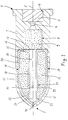
- the exemplary embodiment of a pyrotechnic gas generator shown in FIG. 1 contains a cartridge housing 1 which is rotationally symmetrical with respect to its longitudinal axis 2. At its rear end 3 (right end according to FIG. 1), the cartridge housing 1 has a recess 4 in which an ignition device 5 of a known type with an electrical or mechanical igniter with an ignition charge is arranged.
- An axial ignition channel 6 connects to the recess 4 in the direction of the front end 7 (left end according to FIG. 1) of the cartridge housing 1.
- the ignition channel 6 opens into a first cavity 8, in which a first charge of primary agent or initial charge 9 of a propellant set of the gas generator is arranged.
- the first cavity 8 is followed by a second cavity 10 with a larger cross section than the first cavity 8.
- This second cavity 10 has an approximately cylindrical basic shape and tapers towards the front end 7 of the cartridge housing 1 into a curve 10 that closes the cavity 10 or a tip 11 shown in FIG. B. is formed by pressing together the front annular wall portion 12 of
- a second propellant charge or main charge 13 of the propellant set is contained in an annular, cup-like secondary housing 14 which is arranged in the second cavity 10 of the cartridge housing 1, the cross section of the secondary housing 14 being matched to the cross section of the cavity 10.
- An annular bottom wall piece 15 of the secondary housing 14 lies on a shoulder 16 at the transition from the first to the second cavity 8 or 10 to, wherein a cover plate 17 may be interposed between the paragraph 14 and the bottom wall piece 15 to the z.
- the cover plate 17 consists of a material which can be easily torn open by the compressed gas of the initial charge 9, for. B. from cardboard, plastic or the like.
- the secondary housing 14 has a tubular inner partition or boundary wall 18, which forms a central axial longitudinal channel 19 through the main charge 13 and thus an inner boundary of the main charge 13 to the longitudinal channel 19.
- An annular outer wall 20 of the secondary housing 14 abuts an outer wall 21 of the cartridge housing 1 surrounding the second cavity 10, is adapted in its front section 22 to the inside of the tapered outer wall 21 of the cartridge housing 1 and, as shown, can also be in the axial direction Stand front end 7 beyond the inner boundary wall 18.
- the front section 22 of the outer wall 20 is deformed symmetrically to the longitudinal axis 2 in the form of a projectile tip in the manufacture of the unit consisting of the main charge 13 with its secondary housing 14, so that the annular interior for the main charge 13 by contact of the front section 22 of the outer wall 20 with the front edge 23 of the inner boundary wall 18 is closed in the axial direction and also the longitudinal channel 19 is largely or completely closed by pressing together the outer wall 20 in the tip.
- the front annular wall region 12 of the cartridge housing 1 is deformed in the direction of the longitudinal axis 2, the outer wall 21 of the cartridge being deformed against the front section 22 of the outer wall 20 of the Adapts secondary housing 14 and thus closes the original opening of the cavity 10.
- the secondary housing 14 contains an ignition control device 24, which in the tubular inner boundary wall 18 has a plurality of radial through holes or openings 25 which are uniformly distributed on the circumference of the boundary wall 18 and are arranged in the vicinity of the open front end of the longitudinal channel 19. According to In the illustration in FIG. 1, four openings 25 are provided by way of example, but the number and the arrangement and also the respective diameter of the openings 25 can be varied in order to obtain a desired response or ignition behavior of the ignition control device 24.
- the ignition device 5 When the ignition device 5 is triggered, its ignition charge ignites the initial charge 9 via the ignition channel 6.
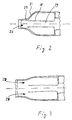
- the compressed gas front meets the inside of the inside curved outer wall 22 of the secondary housing 14 and presses this together with the front wall section 12 of the cartridge housing 1 to the outside, an opening 26 (see schematic representation in FIG. 2) forming for the outflow of the compressed gas.
- Notches or weakenings 27 can be provided on the outer walls 21 or 22 in order to promote the bending of the outer walls 21, 22 at defined points.
- the tip 11 can also be made with a small initial opening 26 so that a first quantity of compressed gas can escape before the two outer walls 21, 22 are bent open.
- the compressed gas front flows through the longitudinal channel 19, it passes through the openings 25 of the ignition control device 24, through which it hits the main charge 13 and ignites it. Due to a short delay until the ignition, the pressure gas formation of the main charge 13 only begins after the pressure gas of the initial charge 9 has expanded the housing opening 26 and a first, comparatively smoothly acting drive effect on movable parts, for. B. a belt tensioner of a motor vehicle or an inflatable airbag.
- the compressed gas of the main charge 13 expands the outer walls 21, 22 and enlarges the front housing opening 26, an annular opening 28 being formed between the front end 23 of the tubular inner boundary wall 18 and the outer wall 22, via which the compressed gas of the main charge 13 can flow out quickly.
- the two additive pressure curves result in a gentle increase in the drive effect by the initial charge 9 and a subsequent use of the main charge 13, which results in a delay continuous pressure increase to a maximum value with a subsequent high pressure level when the main charge 13 burns.
- the initial charge 9 can also be arranged in a ring shape instead of in a cylindrical arrangement in the cavity 8.
- the main charge 13 is then arranged in an approximately cylindrical secondary housing in the cavity 10, the outside diameter of the secondary housing being smaller than the inside diameter of the cavity 10, so that an annular flow channel for the compressed gas of the initial charge 9 is formed.
- the outer boundary wall surrounding the main charge 13 then contains the openings of the ignition control device 24.
Landscapes
- Engineering & Computer Science (AREA)
- Mechanical Engineering (AREA)
- Physics & Mathematics (AREA)
- Fluid Mechanics (AREA)
- Air Bags (AREA)
Abstract
Description
Die Erfindung betrifft einen pyrotechnischen Gasgenerator mit den Merkmalen des Oberbegriffs des Anspruchs 1.The invention relates to a pyrotechnic gas generator with the features of the preamble of
Aus der DE 42 28 696 A1 ist ein derartiger Gasgenerator bekannt, in dessen Gehäuse in Längsrichtung hintereinander eine Zündeinrichtung an einem Gehäuseende, eine erste Treibladung und schließlich eine zweite Treibladung benachbart zu einer Austrittsöffnung am anderen Gehäuseende angeordnet sind, so daß von der Zündeinrichtung die erste Treibladung gezündet wird und durch deren Expansion die zweite Treibladung gezündet wird.Such a gas generator is known from DE 42 28 696 A1, in the housing of which an ignition device at one end of the housing, a first propellant charge and finally a second propellant charge are arranged in the longitudinal direction adjacent to an outlet opening at the other end of the housing, so that the first of the ignition device Propellant charge is ignited and the second propellant charge is ignited by its expansion.
Aufgabe der vorliegenden Erfindung ist es, einen pyrotechnischen Gasgenerator der eingangs genannten Art zu verbessern, so daß der Verlauf des Druckanstiegs des erzeugten Druck- oder Antriebsgases im Hinblick auf anzutreibende Teile optimiert ist.The object of the present invention is to improve a pyrotechnic gas generator of the type mentioned at the outset, so that the course of the rise in pressure of the pressure or drive gas generated is optimized with regard to parts to be driven.
Diese Aufgabe wird erfindungsgemäß durch einen pyrotechnischen Gasgenerator mit den Merkmalen des Anspruchs 1 gelöst. Vorteilhafte Ausgestaltungen der Erfindung sind in den abhängigen Ansprüchen angegeben.This object is achieved according to the invention by a pyrotechnic gas generator with the features of
Durch den Austritt des Druckgases der Initialladung stellt der Gasgenerator ein erstes Antriebsgas bereit, das vergleichsweise sanft einsetzt und somit einen Druckverlauf erzeugt, der bewegliche Bauteile ohne extrem große Belastungsspitzen mit beschädigender oder zerstörender Wirkung anfänglich antreiben oder aufblasen kann. Beim Abbrennen des Treibmittels der Initialladung steigt der Druck des Druckgases an. Die Zündsteuereinrichtung bewirkt, daß das Druckgas bei Überschreiten eines Grenzwertes die Hauptladung zündet, deren Druckgas mit derart eingestellter Zeitverzögerung vor dem Abfall des Druckes der Initialladung einsetzt, so daß sich die Gesamtwirkung des aus dem Gehäuse des zwei- oder mehrstufigen Gasgenerators austretenden Druck- oder Antriebsgases kontinuierlich und ohne übermäßige Druckspitzen entwickeln kann. Die Zündsteuereinrichtung kann beispielsweise Sensoren enthalten, die den Druckanstieg messen und eine Zündung der Hauptladung veranlassen. In einer vorteilhaften Ausgestaltung umfaßt die Zündsteuereinrichtung eine die Hauptladung begrenzende Trenn- oder Grenzwand, in der eine oder mehrere Öffnungen oder Bohrungen enthalten sind, durch die das von der Initialladung erzeugte Druckgas hindurch auf die Hauptladung einwirken kann und deren Zündung auslösen kann. Somit sind für die Zündsteuereinrichtung keine bewegliche mechanische oder elektrische Teile erforderlich, die die Funktionsfähigkeit beeinträchtigen könnten.When the compressed gas escapes from the initial charge, the gas generator provides a first drive gas, which is used comparatively gently and thus creates a pressure curve that can initially drive or inflate moving components without extremely large load peaks with a damaging or destructive effect. When the propellant of the initial charge burns off, the pressure of the compressed gas rises. The ignition control device causes the compressed gas to ignite the main charge when a limit value is exceeded, the compressed gas of which starts with a time delay set in this way before the pressure of the initial charge drops, so that the overall effect of the compressed or drive gas emerging from the housing of the two-stage or multi-stage gas generator can develop continuously and without excessive pressure peaks. The Ignition control device can contain, for example, sensors that measure the pressure rise and cause the main charge to ignite. In an advantageous embodiment, the ignition control device comprises a partition or boundary wall delimiting the main charge, in which one or more openings or bores are contained, through which the compressed gas generated by the initial charge can act on the main charge and can trigger its ignition. Thus, no moving mechanical or electrical parts that could impair the functionality are required for the ignition control device.
Das Gehäuse des Gasgenerators kann rechteckig oder zylindrisch, insbesondere rotationssymmetrisch ausgebildet sein, wobei der Gasaustritt auch auf zwei oder mehrere Gehäuseöffnungen aufgeteilt sein kann. Zweckmäßigerweise ist das Gehäuse eine hülsenförmige Kartusche, die an einem Ende die Zündeinrichtung und am gegenüberliegenden Ende die Gehäuseöffnung zum Austritt des Druckgases aufweist. Eine solche Kartusche läßt sich einfach und kostengünstig herstellen, insbesondere wenn sie ein rotationssymmetrisches Teil ist. Gemäß einem Ausführungsbeispiel ist die Gehäuseöffnung für den Druckgasaustritt vor Zündung der Treibmittelladungen geschlossen. Dann sind die Treibmittelladungen gegen Umwelteinflüsse geschützt. Bei Zündung des Gasgenerators wird der Verschluß der Gehäuseöffnung durch die Druckkraft der Initialladung geöffnet. Der Verschluß der Gehäuseöffnung kann ein eingesetztes und an der Kartusche befestigtes Verschlußteil wie z. B. ein Deckel sein. Zweckmäßigerweise wird jedoch der Vorderteil der Kartuschenwand derart zusammengepreßt und verformt, daß die Kartuschenwand den öffenbaren Verschluß der Gehäuseöffnung bildet. Die Kartuschenwand kann derart ausgebildet sein, daß die Initialladung sogleich den maximalen Öffnungsquerschnitt öffnet. Gemäß einer weiteren Ausgestaltung wird durch die Initialladung nur ein erster kleinerer Querschnitt geöffnet, der durch die Hauptladung auf den maximalen Querschnitt geöffnet wird. Damit läßt sich der Druckanstiegsverlauf beeinflussen. Schwächungen der Wandstärke, Einkerbungen in der Wand oder dergleichen an definierten Stellen können die gewünschte Verformung der Außenwand der Kartusche unterstützen.The housing of the gas generator can be rectangular or cylindrical, in particular rotationally symmetrical, and the gas outlet can also be divided into two or more housing openings. The housing is expediently a sleeve-shaped cartridge which has the ignition device at one end and the housing opening at the opposite end for the discharge of the compressed gas. Such a cartridge can be produced easily and inexpensively, especially if it is a rotationally symmetrical part. According to one embodiment, the housing opening for the compressed gas outlet is closed before the propellant charges are ignited. Then the propellant loads are protected against environmental influences. When the gas generator is ignited, the closure of the housing opening is opened by the pressure force of the initial charge. The closure of the housing opening can be an inserted and attached to the cartridge closure part such. B. be a lid. However, the front part of the cartridge wall is expediently pressed and deformed in such a way that the cartridge wall forms the openable closure of the housing opening. The cartridge wall can be designed such that the initial charge immediately opens the maximum opening cross section. According to a further embodiment, the initial charge only opens a first smaller cross section, which is opened to the maximum cross section by the main charge. The course of the pressure rise can thus be influenced. Weaknesses in the wall thickness, indentations in the wall or the like at defined points can support the desired deformation of the outer wall of the cartridge.
Gemäß einer vorteilhaften Ausgestaltung der Erfindung ist die Hauptladung in einem der Gehäuseöffnung benachbarten Hohlraum des Gehäuses und die Initialladung in einem in Richtung der Zündeinrichtung an den Hohlraum der Hauptladung angrenzenden weiteren Hohlraum des Gehäuses enthalten, wobei die Hauptladung ein Sekundärgehäuse aufweist, das zumindest einen von der Grenzwand begrenzten Strömungskanal im Hohlraum zum Abströmen des Druckgases von der Initialladung zur Gehäuseöffnung freiläßt. Diese Gestaltung bildet einen definierten Gasabströmungsweg über einen beliebig, jedoch möglichst strömungsgünstig geführten Strömungskanal an der Hauptladung vorbei. Die Hauptladung ist von dem Strömungskanal durch die Grenzwand getrennt, in der die Öffnungen der Zündsteuereinrichtung enthalten sind.According to an advantageous embodiment of the invention, the main charge is contained in a cavity of the housing adjacent to the housing opening and the initial charge is contained in a further cavity of the housing adjacent to the cavity of the main charge in the direction of the ignition device, the main charge having a secondary housing which has at least one of the Boundary wall delimits flow channel in the cavity for the discharge of the compressed gas from the initial charge to the housing opening. This design forms a defined gas outflow path via an arbitrary, but as flow-free as possible, flow channel past the main charge. The main charge is separated from the flow channel by the boundary wall, in which the openings of the ignition control device are contained.
Zweckmäßigerweise ist das Sekundärgehäuse als napfartiger Ring mit einem zentralen axialen Strömungskanal ausgebildet, da dann das Druckgas der Initialladung auf kürzestem Wege axial aus dem Gehäuse abströmt und dabei die Hauptladung zünden kann. Jedoch kann der Strömungskanal auch als Ringkanal ausgebildet sein, der ein zylindrisches Sekundärgehäuse umgibt. Ein Teil der Initialladung kann auch in einem Teil des Strömungskanals enthalten sein, so daß eine größere Treibladung der Initialladung bei gleichen Kartuschengehäuseabmessungen untergebracht werden kann. Zur Steuerung des Druckverhaltens des Gasgenerators bzw. des Verlaufs des Druckanstiegs können einerseits die Menge der Treibmittelladung in der Initial- und der Hauptladung sowie die Art des Treibmittels, z. B. die Abbrenngeschwindigkeit, variiert werden. Andererseits kann auch die Zündsteuereinrichtung durch Variation der Anzahl, der Positionierung und der Durchmesser der Öffnungen in der Grenzwand die Druckgasentwicklung und somit das Druckverhalten beeinflussen. Schließlich bietet auch die Gestaltung der Spitze der Kartusche und das Öffnungsverhalten des Verschlusses der Gehäuseöffnung die Möglichkeit der Beeinflussung des Druckverhaltens.The secondary housing is expediently designed as a cup-like ring with a central axial flow channel, since then the compressed gas of the initial charge flows axially out of the housing in the shortest possible way and can thereby ignite the main charge. However, the flow channel can also be designed as an annular channel which surrounds a cylindrical secondary housing. Part of the initial charge can also be contained in part of the flow channel, so that a larger propellant charge of the initial charge can be accommodated with the same cartridge housing dimensions. To control the pressure behavior of the gas generator or the course of the pressure rise, on the one hand, the amount of propellant charge in the initial and main charge and the type of propellant, e.g. B. the burning rate can be varied. On the other hand, the ignition control device can also influence the pressure gas development and thus the pressure behavior by varying the number, the positioning and the diameter of the openings in the boundary wall. Finally, the design of the tip of the cartridge and the opening behavior of the closure of the housing opening also offer the possibility of influencing the pressure behavior.
Die beschriebene Hauptladung kann auch auf mehrere Einzelladungen aufgeteilt sein, die gemeinsam oder nacheinander von der Zündsteuereinrichtung gezündet werden können, um ein optimales Druckverhalten zu erreichen.The main charge described can also be divided into a plurality of individual charges, which can be ignited together or in succession by the ignition control device in order to achieve optimum pressure behavior.
Nachfolgend wird die Erfindung anhand eines Ausführungsbeispiels unter Bezugnahme auf Zeichnungen näher beschrieben. Es zeigt:
- Fig. 1
- in vergrößerter Querschnittsansicht einen erfindungsgemäßen Gasgenerator;
- Fig. 2
- in schematischer Darstellung einen Ausschnitt der Fig. 1 mit teilweise geöffneter Gehäuseöffnung für einen Gasaustritt; und
- Fig. 3
- eine Ansicht gemäß Fig. 2 mit vollständig geöffneter Gehäuseöffnung.
- Fig. 1
- an enlarged cross-sectional view of a gas generator according to the invention;
- Fig. 2
- a schematic representation of a section of Figure 1 with a partially open housing opening for a gas outlet. and
- Fig. 3
- a view of FIG. 2 with the housing opening fully open.
Das in Fig. 1 dargestellte Ausführungsbeispiel eines pyrotechnischen Gasgenerators enthält ein Kartuschengehäuse 1, das bezüglich seiner Längsachse 2 rotationssymmetrisch ist. An seinem Hinterende 3 (rechtes Ende gemäß Fig. 1) weist das Kartuschengehäuse 1 eine Ausnehmung 4 auf, in der eine Zündeinrichtung 5 bekannter Bauart mit einem elektrischen oder mechanischen Zünder mit einer Zündladung angeordnet ist. An die Ausnehmung 4 schließt sich ein axialer Zündkanal 6 in Richtung zum Vorderende 7 (linkes Ende gemäß Fig. 1) des Kartuschengehäuses 1 an. Der Zündkanal 6 mündet in einen ersten Hohlraum 8, in dem eine erste Trebmittelladung oder Initialladung 9 eines Treibmittelsatzes des Gasgenerators angeordnet ist. An den ersten Hohlraum 8 schließt sich ein zweiter Hohlraum 10 von bezüglich dem ersten Hohlraum 8 größerem Querschnitt an. Dieser zweite Hohlraum 10 weist eine in etwa zylindrische Grundform auf und verjüngt sich zum Vorderende 7 des Kartuschengehäuses 1 hin in eine den Hohlraum 10 abschließende Rundung oder eine in Fig. 1 dargestellte Spitze 11, die bei der Herstellung des Gasgenerators z. B. durch Zusammenpressen des vorderen ringförmigen Wandbereiches 12 des Kartuschengehäuses 1 gebildet wird.The exemplary embodiment of a pyrotechnic gas generator shown in FIG. 1 contains a
Eine zweite Treibmittelladung oder Hauptladung 13 des Treibmittelsatzes ist in einem ringförmigen, napfartigen Sekundärgehäuse 14 enthalten, das in dem zweiten Hohlraum 10 des Kartuschengehäuses 1 angeordnet ist, wobei der Querschnitt des Sekundärgehäuses 14 dem Querschnitt des Hohlraumes 10 angepaßt ist. Ein ringförmiges Bodenwandstück 15 des Sekundärgehäuses 14 liegt an einem Absatz 16 am Übergang vom ersten zum zweiten Hohlraum 8 bzw. 10 an, wobei eine Abdeckscheibe 17 zwischen dem Absatz 14 und dem Bodenwandstück 15 zwischengelegt sein kann, um das z. B. pulverförmige Treibmittel der Initialladung 9 abzudecken und in dem ersten Hohlraum 8 zu halten. Die Abdeckscheibe 17 besteht aus einem durch das Druckgas der Initialladung 9 leicht aufreißbaren Material, z. B. aus Karton, Kunststoff oder dergleichen.A second propellant charge or
Das Sekundärgehäuse 14 weist eine rohrförmige innere Trenn- oder Grenzwand 18 auf, die einen zentralen axialen Längskanal 19 durch die Hauptladung 13 und somit eine innenseitige Abgrenzung der Hauptladung 13 zu dem Längskanal 19 hin bildet. Eine ringförmige Außenwand 20 des Sekundärgehäuses 14 liegt an einer den zweiten Hohlraum 10 umgebenden Außenwand 21 des Kartuschengehäuses 1 an, ist in ihrem Vorderabschnitt 22 an die Innenseite der sich verjüngenden Außenwand 21 des Kartuschengehäuses 1 angepaßt und kann auch, wie dargestellt, in axialer Richtung zum Vorderende 7 hin über die innere Grenzwand 18 hinausstehen. Der Vorderabschnitt 22 der Außenwand 20 wird bei der Herstellung der aus der Hauptladung 13 mit ihrem Sekundärgehäuse 14 bestehenden Einheit symmetrisch zur Längsachse 2 in die Form einer Geschoßspitze verformt, so daß der ringförmige Innenraum für die Hauptladung 13 durch Kontakt des Vorderabschnittes 22 der Außenwand 20 mit dem Vorderrand 23 der inneren Grenzwand 18 in axialer Richtung abgeschlossen wird und auch der Längskanal 19 durch Zusammenpressen der Außenwand 20 in der Spitze weitgehend oder vollständig geschlossen wird.The
Bei der Fertigung des Gasgenerators wird, wie schon angesprochen, nach dem Einsetzen des Sekundärgehäuses 14 in das Kartuschengehäuse 1 der vordere ringförmige Wandbereich 12 des Kartuschengehäuses 1 in Richtung zur Längsachse 2 hin verformt, wobei sich die Kartuschenaußenwand 21 an den Vorderabschnitt 22 der Außenwand 20 des Sekundärgehäuses 14 anpaßt und somit die ursprüngliche Öffnung des Hohlraumes 10 schließt.In the manufacture of the gas generator, as already mentioned, after inserting the
Das Sekundärgehäuse 14 enthält eine Zündsteuereinrichtung 24, die in der rohrförmigen inneren Grenzwand 18 mehrere radiale, am Umfang der Grenzwand 18 gleichmäßig verteilte Durchgangsbohrungen oder Öffnungen 25 aufweist, die in der Nähe des offenen Vorderendes des Längskanals 19 angeordnet sind. Gemäß der Darstellung in Fig. 1 sind beispielhaft vier Öffnungen 25 vorgesehen, jedoch kann die Anzahl und die Anordnung sowie auch der jeweilige Durchmesser der Öffnungen 25 variiert werden, um ein gewünschtes Ansprechen oder Zündverhalten der Zündsteuereinrichtung 24 zu erhalten.The
Bei Auslösung der Zündeinrichtung 5 zündet ihre Zündladung über den Zündkanal 6 die Initialladung 9. Das beim Abbrennen des Treibmittels entstehende Druckgas zerreißt die Abdeckscheibe 17 und strömt durch den Längskanal 19 in Richtung zum Vorderende 7 des Kartuschengehäuses 1. Die Druckgasfront trifft auf die Innenseite der einwärts gebogenen Außenwand 22 des Sekundärgehäuses 14 und drückt diese zusammen mit dem vorderen Wandabschnitt 12 des Kartuschengehäuses 1 nach außen, wobei sich eine Öffnung 26 (siehe schematisierte Darstellung in Fig. 2) zum Ausströmen des Druckgases bildet. Einkerbungen oder Schwächungen 27 können an den Außenwänden 21 bzw. 22 vorgesehen sein, um das Aufbiegen der Außenwände21, 22 an definierten Stellen zu fördern. Die Spitze 11 kann auch mit einer kleinen Anfangsöffnung 26 gefertigt sein, so daß eine erste Druckgasmenge austreten kann, bevor das Aufbiegen der beiden Außenwände 21, 22 erfolgt. Während die Druckgasfront durch den Längskanal 19 strömt, passiert sie die Öffnungen 25 der Zündsteuereinrichtung 24, durch die sie auf die Hauptladung 13 trifft und diese entzündet. Aufgrund einer kurzen Verzögerung bis zur Zündung setzt die Druckgasbildung der Hauptladung 13 erst dann ein, nachdem das Druckgas der Initialladung 9 die Gehäuseöffnung 26 aufgeweitet hat und eine erste, vergleichsweise sanft einsetzende Antriebswirkung auf bewegbare Teile, z. B. einer Gurtstraffereinrichtung eines Kraftfahrzeuges oder eines aufzublasenden Airbags, ausgeübt hat.When the
Das Druckgas der Hauptladung 13 erweitert die Außenwände 21, 22 und vergrößert die vordere Gehäuseöffnung 26, wobei eine ringförmige Öffnung 28 zwischen dem Vorderende 23 der rohrförmigen inneren Grenzwand 18 und der Außenwand 22 entsteht, über die das Druckgas der Hauptladung 13 schnell ausströmen kann. Die beiden sich addierenden Druckverläufe ergeben einen sanften Anstieg der Antriebswirkung durch die Initialladung 9 und einen sich mit definierter Verzögerung anschließenden Einsatz der Hauptladung 13, der zu einem kontinuierlichen Druckanstieg auf einen Maximalwert mit anschließendem hohen Druckniveau beim Abbrennen der Hauptladung 13 führt.The compressed gas of the
Die Initialladung 9 kann anstatt in zylindrischer Anordnung im Hohlraum 8 auch ringförmig angeordnet sein. Dann ist die Hauptladung 13 in einem in etwa zylindrischen Sekundärgehäuse im Hohlraum 10 angeordnet, wobei der Außendurchmesser des Sekundärgehäuses kleiner ist wie der Innendurchmesser des Hohlraumes 10, so daß ein ringförmiger Strömungskanal für das Druckgas der Initialladung 9 gebildet ist. Die die Hauptladung 13 umgebende äußerer Grenzwand enthält dann die Öffnungen der Zündsteuereinrichtung 24.The initial charge 9 can also be arranged in a ring shape instead of in a cylindrical arrangement in the
Claims (16)
dadurch gekennzeichnet,
characterized,
Applications Claiming Priority (2)
| Application Number | Priority Date | Filing Date | Title |
|---|---|---|---|
| DE1995144784 DE19544784C2 (en) | 1995-11-30 | 1995-11-30 | Pyrotechnic gas generator |
| DE19544784 | 1995-11-30 |
Publications (2)
| Publication Number | Publication Date |
|---|---|
| EP0776796A2 true EP0776796A2 (en) | 1997-06-04 |
| EP0776796A3 EP0776796A3 (en) | 1997-12-10 |
Family
ID=7778896
Family Applications (1)
| Application Number | Title | Priority Date | Filing Date |
|---|---|---|---|
| EP96119171A Ceased EP0776796A3 (en) | 1995-11-30 | 1996-11-29 | Pyrotechnic gas generator |
Country Status (2)
| Country | Link |
|---|---|
| EP (1) | EP0776796A3 (en) |
| DE (1) | DE19544784C2 (en) |
Cited By (4)
| Publication number | Priority date | Publication date | Assignee | Title |
|---|---|---|---|---|
| EP0867347A2 (en) * | 1997-03-24 | 1998-09-30 | Daicel Chemical Industries, Ltd. | Gas generating pellets, gas generator and air bag apparatus |
| EP0926015A2 (en) * | 1997-12-26 | 1999-06-30 | Daicel Chemical Industries, Ltd. | An airbag gas generator and an airbag apparatus |
| US6562161B1 (en) | 1997-03-24 | 2003-05-13 | Daicel Chemical Industries, Ltd. | Gas generating compositions for air bag |
| WO2013133349A1 (en) * | 2012-03-06 | 2013-09-12 | Daicel Corporation | Gas generator for restraining device |
Families Citing this family (4)
| Publication number | Priority date | Publication date | Assignee | Title |
|---|---|---|---|---|
| US6116642A (en) * | 1998-04-27 | 2000-09-12 | Trw Inc. | Inflator for inflating an inflatable vehicle occupant protection device |
| DE102015009001B4 (en) * | 2015-07-10 | 2021-10-28 | Nitrochemie Aschau Gmbh | Pyrotechnic gas generator |
| DE102015220108B4 (en) * | 2015-10-15 | 2017-12-28 | Takata AG | Gas generator assembly with combustion chamber |
| DE102016015042B4 (en) | 2016-12-16 | 2018-08-23 | Diehl Defence Gmbh & Co. Kg | Ammunition module, warhead and ammunition |
Citations (1)
| Publication number | Priority date | Publication date | Assignee | Title |
|---|---|---|---|---|
| DE4228696A1 (en) | 1992-08-28 | 1994-03-03 | Hs Tech & Design | Pyrotechnic gas generator |
Family Cites Families (6)
| Publication number | Priority date | Publication date | Assignee | Title |
|---|---|---|---|---|
| US3715131A (en) * | 1971-06-04 | 1973-02-06 | Hercules Inc | Chemical gas generating device for an automobile safety system |
| DE2364268C3 (en) * | 1973-12-22 | 1980-07-03 | Rudolf 8025 Unterhaching Reiter | Solid gas generator, in particular for inflating a gas bag used to protect vehicle occupants |
| DE4019677A1 (en) * | 1990-06-20 | 1992-01-09 | Bayern Chemie Gmbh Flugchemie | Gas generator for airbag system - operates in two stages to minimise bag kinetic energy |
| DE4019877A1 (en) * | 1990-06-22 | 1992-01-09 | Bayern Chemie Gmbh Flugchemie | Gas generator for vehicle airbag - with delay channel to retard pressure increase on detonation |
| SE9202078D0 (en) * | 1992-07-06 | 1992-07-06 | Bergslagens Produktutveckling | LIGHTING DEVICE FOR GAS GENERATORS |
| US5345875A (en) * | 1993-07-07 | 1994-09-13 | Automotive Systems Laboratory, Inc. | Gas generator |
-
1995
- 1995-11-30 DE DE1995144784 patent/DE19544784C2/en not_active Expired - Fee Related
-
1996
- 1996-11-29 EP EP96119171A patent/EP0776796A3/en not_active Ceased
Patent Citations (1)
| Publication number | Priority date | Publication date | Assignee | Title |
|---|---|---|---|---|
| DE4228696A1 (en) | 1992-08-28 | 1994-03-03 | Hs Tech & Design | Pyrotechnic gas generator |
Cited By (12)
| Publication number | Priority date | Publication date | Assignee | Title |
|---|---|---|---|---|
| EP0867347A2 (en) * | 1997-03-24 | 1998-09-30 | Daicel Chemical Industries, Ltd. | Gas generating pellets, gas generator and air bag apparatus |
| EP0867347A3 (en) * | 1997-03-24 | 1999-11-10 | Daicel Chemical Industries, Ltd. | Gas generating pellets, gas generator and air bag apparatus |
| US6562161B1 (en) | 1997-03-24 | 2003-05-13 | Daicel Chemical Industries, Ltd. | Gas generating compositions for air bag |
| EP0926015A2 (en) * | 1997-12-26 | 1999-06-30 | Daicel Chemical Industries, Ltd. | An airbag gas generator and an airbag apparatus |
| EP0926015A3 (en) * | 1997-12-26 | 2000-05-24 | Daicel Chemical Industries, Ltd. | An airbag gas generator and an airbag apparatus |
| US6540256B2 (en) | 1997-12-26 | 2003-04-01 | Daicel Chemical Industries, Ltd. | Airbag gas generator and an airbag apparatus |
| US6942249B2 (en) | 1997-12-26 | 2005-09-13 | Daicel Chemical Industries, Ltd. | Airbag gas generator and an airbag apparatus |
| WO2013133349A1 (en) * | 2012-03-06 | 2013-09-12 | Daicel Corporation | Gas generator for restraining device |
| JP2013184482A (en) * | 2012-03-06 | 2013-09-19 | Daicel Corp | Gas generator for occupant restraining device |
| US8720947B2 (en) | 2012-03-06 | 2014-05-13 | Daicel Corporation | Gas generator for restraining device |
| CN104159792A (en) * | 2012-03-06 | 2014-11-19 | 株式会社大赛璐 | Gas generator for restraining device |
| CN104159792B (en) * | 2012-03-06 | 2016-12-14 | 株式会社大赛璐 | Gas generator for restraint device |
Also Published As
| Publication number | Publication date |
|---|---|
| DE19544784A1 (en) | 1997-06-05 |
| EP0776796A3 (en) | 1997-12-10 |
| DE19544784C2 (en) | 2003-02-13 |
Similar Documents
| Publication | Publication Date | Title |
|---|---|---|
| DE3147780C2 (en) | ||
| EP0782945B1 (en) | Gas generator for a vehicle restraint system | |
| EP2195205B1 (en) | Gas generator for an air bag module | |
| DE19527621A1 (en) | Cartridge ammunition | |
| DE102007016778A1 (en) | Gas generating system for vehicle occupant protection system, has valve mechanism which is coupled to divider for contracting flow path according to pressure in enclosure so that pressure in enclosure is retained at fixed range | |
| DE4324554B4 (en) | Gas generator, in particular for an airbag | |
| DE4228696C2 (en) | Pyrotechnic gas generator | |
| EP1012005B1 (en) | Gas generator | |
| EP0776796A2 (en) | Pyrotechnic gas generator | |
| DE69920615T2 (en) | Piston drive for straining a safety belt | |
| EP0944504B1 (en) | Hybrid gas generator for airbag | |
| EP1433671B1 (en) | Gasgenerator | |
| EP1491413A2 (en) | Gas generator | |
| WO2019020414A1 (en) | Overigniting protection device, second ignition stage, gas generator and airbag module | |
| DE4124490A1 (en) | PLASTIC CARTRIDGE AND PLASTIC CARTRIDGE TAPE MAGAZINE | |
| DE4234276C1 (en) | Gas generator with ignition and propellant charges - useful for rapid operation of seat belt tightener or air-bag | |
| EP0882627B1 (en) | Gas generator and method of operating a gas generator | |
| EP0835789B1 (en) | Pressure accumulator for a vehicle passenger restraint system | |
| DE4213265C2 (en) | LPG generator assembly | |
| EP0882628A1 (en) | Gas generator | |
| DE202005016885U1 (en) | Gas generator for a vehicle air bag includes a plastic base extending to form e.g. a combustion chamber with the detonator front surface and side wall | |
| DE19738937C2 (en) | Cartridge ammunition | |
| DE602005006148T2 (en) | PYROTECHNICAL ACTUATOR WITH CONTROLLABLE FORCE AND OPTIMIZED GEOMETRY | |
| DE3717458A1 (en) | Pyrotechnic force element | |
| DE19804655C2 (en) | Airbag module with cover caps that can be moved to the side |
Legal Events
| Date | Code | Title | Description |
|---|---|---|---|
| PUAI | Public reference made under article 153(3) epc to a published international application that has entered the european phase |
Free format text: ORIGINAL CODE: 0009012 |
|
| AK | Designated contracting states |
Kind code of ref document: A2 Designated state(s): AT DE ES FR GB IT |
|
| PUAL | Search report despatched |
Free format text: ORIGINAL CODE: 0009013 |
|
| AK | Designated contracting states |
Kind code of ref document: A3 Designated state(s): AT DE ES FR GB IT |
|
| 17P | Request for examination filed |
Effective date: 19980605 |
|
| 17Q | First examination report despatched |
Effective date: 20000112 |
|
| STAA | Information on the status of an ep patent application or granted ep patent |
Free format text: STATUS: THE APPLICATION HAS BEEN REFUSED |
|
| 18R | Application refused |
Effective date: 20010106 |