EP0769399A2 - Vehicle heating device - Google Patents
Vehicle heating device Download PDFInfo
- Publication number
- EP0769399A2 EP0769399A2 EP96115780A EP96115780A EP0769399A2 EP 0769399 A2 EP0769399 A2 EP 0769399A2 EP 96115780 A EP96115780 A EP 96115780A EP 96115780 A EP96115780 A EP 96115780A EP 0769399 A2 EP0769399 A2 EP 0769399A2
- Authority
- EP
- European Patent Office
- Prior art keywords
- fuel gas
- supply line
- gas supply
- combustion
- combustion air
- Prior art date
- Legal status (The legal status is an assumption and is not a legal conclusion. Google has not performed a legal analysis and makes no representation as to the accuracy of the status listed.)
- Granted
Links
- 238000010438 heat treatment Methods 0.000 title description 2
- 238000002485 combustion reaction Methods 0.000 claims abstract description 38
- 239000000567 combustion gas Substances 0.000 claims abstract description 10
- 239000012528 membrane Substances 0.000 claims abstract description 9
- 239000002737 fuel gas Substances 0.000 claims description 43
- 239000000203 mixture Substances 0.000 claims description 9
- 239000000446 fuel Substances 0.000 claims 1
- 239000007789 gas Substances 0.000 abstract description 9
- XLYOFNOQVPJJNP-UHFFFAOYSA-N water Substances O XLYOFNOQVPJJNP-UHFFFAOYSA-N 0.000 description 9
- UGFAIRIUMAVXCW-UHFFFAOYSA-N Carbon monoxide Chemical compound [O+]#[C-] UGFAIRIUMAVXCW-UHFFFAOYSA-N 0.000 description 3
- 239000003546 flue gas Substances 0.000 description 3
- 238000002360 preparation method Methods 0.000 description 3
- 238000013021 overheating Methods 0.000 description 2
- 241001156002 Anthonomus pomorum Species 0.000 description 1
- 230000000712 assembly Effects 0.000 description 1
- 238000000429 assembly Methods 0.000 description 1
- 238000010276 construction Methods 0.000 description 1
- 230000001276 controlling effect Effects 0.000 description 1
- 238000004519 manufacturing process Methods 0.000 description 1
- 230000036316 preload Effects 0.000 description 1
- 230000005855 radiation Effects 0.000 description 1
- 230000001105 regulatory effect Effects 0.000 description 1
- 238000011144 upstream manufacturing Methods 0.000 description 1
Images

Classifications
-
- B—PERFORMING OPERATIONS; TRANSPORTING
- B60—VEHICLES IN GENERAL
- B60H—ARRANGEMENTS OF HEATING, COOLING, VENTILATING OR OTHER AIR-TREATING DEVICES SPECIALLY ADAPTED FOR PASSENGER OR GOODS SPACES OF VEHICLES
- B60H1/00—Heating, cooling or ventilating [HVAC] devices
- B60H1/22—Heating, cooling or ventilating [HVAC] devices the heat being derived otherwise than from the propulsion plant
- B60H1/2203—Heating, cooling or ventilating [HVAC] devices the heat being derived otherwise than from the propulsion plant the heat being derived from burners
-
- B—PERFORMING OPERATIONS; TRANSPORTING
- B60—VEHICLES IN GENERAL
- B60H—ARRANGEMENTS OF HEATING, COOLING, VENTILATING OR OTHER AIR-TREATING DEVICES SPECIALLY ADAPTED FOR PASSENGER OR GOODS SPACES OF VEHICLES
- B60H1/00—Heating, cooling or ventilating [HVAC] devices
- B60H1/22—Heating, cooling or ventilating [HVAC] devices the heat being derived otherwise than from the propulsion plant
- B60H2001/2228—Heating, cooling or ventilating [HVAC] devices the heat being derived otherwise than from the propulsion plant controlling the operation of heaters
- B60H2001/2231—Heating, cooling or ventilating [HVAC] devices the heat being derived otherwise than from the propulsion plant controlling the operation of heaters for proper or safe operation of the heater
-
- B—PERFORMING OPERATIONS; TRANSPORTING
- B60—VEHICLES IN GENERAL
- B60H—ARRANGEMENTS OF HEATING, COOLING, VENTILATING OR OTHER AIR-TREATING DEVICES SPECIALLY ADAPTED FOR PASSENGER OR GOODS SPACES OF VEHICLES
- B60H1/00—Heating, cooling or ventilating [HVAC] devices
- B60H1/22—Heating, cooling or ventilating [HVAC] devices the heat being derived otherwise than from the propulsion plant
- B60H2001/2268—Constructional features
- B60H2001/2281—Air supply, exhaust systems
-
- B—PERFORMING OPERATIONS; TRANSPORTING
- B60—VEHICLES IN GENERAL
- B60H—ARRANGEMENTS OF HEATING, COOLING, VENTILATING OR OTHER AIR-TREATING DEVICES SPECIALLY ADAPTED FOR PASSENGER OR GOODS SPACES OF VEHICLES
- B60H1/00—Heating, cooling or ventilating [HVAC] devices
- B60H1/22—Heating, cooling or ventilating [HVAC] devices the heat being derived otherwise than from the propulsion plant
- B60H2001/2268—Constructional features
- B60H2001/2284—Fuel supply
Definitions
- the invention relates to a vehicle heart device with a burner, to which combustion air is supplied via combustion air inlet openings by means of a blower and to which combustion gas is also supplied via a combustion gas supply line according to the preamble of patent claim 1.
- a control device for a gas burner in which the differential pressure of a fan that delivers combustion air is used to actuate a servo valve, which in turn is used to control a relatively complicated gas control valve.
- a gas-heated water heater which otherwise fulfills the features of the preamble of claim 1, is known from DE-A1 23 36 683.
- the fuel gas is supplied to the burner at a pressure which is above atmospheric pressure, so that a solenoid valve controlled by an electronic control unit is indispensable for controlling the gas supply.
- the invention has for its object to provide a vehicle heater with a burner in which the production of the fuel gas / combustion air mixture is significantly simplified and improved.
- a solenoid valve controlled by a control device is superfluous.
- the supply of the fuel gas is controlled directly by the negative pressure generated by the combustion air fan on the suction side.
- This Direct control by the blower also enables the burner to be regulated in a certain range, since with a corresponding design of the valve or switch at a higher speed, ie with a higher suction-side vacuum of the blower, a larger amount of gas can also be provided.
- the vehicle heater offers an automatic high safety standard, since if the combustion air blower fails or is blocked, the pressure drop ensures that the fuel gas inlet opening is closed immediately.
- valve or the switch is actuated by means of a membrane, which causes the fuel gas supply line to be closed when the fan is at a standstill or at a very slow speed.
- a membrane which causes the fuel gas supply line to be closed when the fan is at a standstill or at a very slow speed.
- Such a switch designed with a membrane can be produced particularly inexpensively.
- This embodiment becomes simple when the fuel gas at the fuel gas inlet opening has a negative pressure of about 10-20 pa relative to the atmospheric pressure and when the membrane is in direct contact with the fuel gas inlet opening.
- a fuel gas inlet opening arranged downstream of the fuel gas supply line and the combustion air inlet openings open at an angle to one another at a common mixing device. It had proven particularly advantageous if the combustion air inlet openings open into the mixing device as radial bores, while the combustion gas inlet opening is designed as a tangential bore.
- the preparation of the combustion air / fuel gas mixture is additionally improved in that a guide device for swirling the mixture is arranged between the fan and the combustion chamber and in that the mixing device is protected by a heat shield against heat reflection from the side of the combustion chamber.
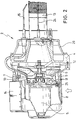
- a vehicle heater 1 has a burner 2 and a heat exchanger 3 as main assemblies, which are connected to one another on a common flange part 4.
- An electric motor 5 is arranged in the burner 2 and drives a blower 6 for the conveyance of combustion air.
- a mixing device 7 is provided on the suction side of the blower 6. On the one hand, this is connected to a combustion air supply 8, which is provided in an outer wall of a housing part 9, which surrounds the electric motor 5 and the mixing device 7.
- the mixing device 7 is designed as a flat cylindrical part, the outer wall of which is penetrated by a plurality of radially opening combustion air inlet openings 10, which are connected to the combustion air supply 8 within the housing part 9.
- the mixing device 7 is provided with a tangentially opening fuel gas inlet opening 11. Combustion air inlet openings 10 and combustion gas inlet opening 11 thus form a right angle to one another, which ensures particularly good mixing.
- the fuel gas inlet opening 11 is connected upstream via a vacuum valve 25, which can also be designed as a vacuum switch, to a fuel gas supply line 26.
- an ignition electrode 15 is provided parallel to the outer wall of the bored combustion chamber 13, which has a Ignition spark generator 14 arranged on the outside of the housing part 9 is supplied with corresponding electrical energy.
- the combustion gases leave the combustion chamber 13 on the end face opposite the flange part 4, where they are deflected and discharged from the vehicle heater 1 via a flue gas duct 16 and an exhaust pipe 17.
- the essential part of the thermal energy is extracted from them via the heat exchanger 3.
- water is supplied to the heat exchanger 3 via a water inlet 18, which flows in countercurrent through a water jacket 19 which spirally surrounds the flue gas channel 16 and leaves the vehicle heating device 1 at a water outlet 18.
- an overheating fuse 21 and a thermostat 22 are provided on the housing and are connected to a control unit 23.
- the schematically illustrated vacuum valve 25 has a chamber into which the fuel gas supply line 26 opens on one side and the other end is in flow connection with the fuel gas inlet opening 11.
- a membrane 27 is held by holders 28, which, depending on the pressure conditions prevailing in the chamber in accordance with the arrows shown in FIG. suction pressure generated by the blower 6 moves to the left away from this opening and thereby enables the supply of fuel gas to the fuel gas inlet opening 11.
- the fuel gas is made available in the fuel gas supply line 26 with a slight overpressure, in which case the membrane 27 has a low resilient preload, which the fan 6 prevents the fuel gas supply line 26 from becoming blocked when there is no suction pressure can be created at the junction.
- the resilient bias of the diaphragm 27 is then designed so that it is overcome by the suction pressure 6 building up with increasing fan speed and leads to an increasing lifting of the diaphragm 27.
- the supply of the fuel gas, controlled by the suction pressure of the blower 6, on the one hand enables a simple construction of a vehicle heater.
- the suction-side supply of the fuel gas, preferably under a negative pressure, its subsequent mixing in the mixing device 7, as well as the subsequent chopping by the blower 6 and the additional swirling of the mixture in the guide device 12 ensure excellent preparation of the fuel gas / combustion air mixture excellent calorific values.
- a heat shield 29 arranged between the combustion chamber 13 and the mixing device 7 protects the latter from harmful heat radiation on the part of the combustion chamber and thereby enables reliable mixture preparation free of major temperature fluctuations despite the compact, integrated arrangement of the mixing device 7 in the vehicle heater 1.
Abstract
Description
Die Erfindung betrifft ein Fahrzeugherzgerät mit einem Brenner, dem Brennluft über Brennlufteintrittsöffnungen mittels eines Gebläses und dem ferner Brenngas über eine Brenngaszufuhrleitung zugeführt wird gemäß dem Oberbegriff des Patentanspruchs 1.The invention relates to a vehicle heart device with a burner, to which combustion air is supplied via combustion air inlet openings by means of a blower and to which combustion gas is also supplied via a combustion gas supply line according to the preamble of patent claim 1.
Aus der DE 39 11 268 A1 ist eine Regeleinrichtung für einen Gasbrenner bekannt, bei dem der Differenzdruck eines Brennluft fördernden Gebläses zur Betätigung eines Servoventils verwendet wird, welches seinerseits zur Ansteuerung eines relativ kompliziert aufgebauten Gasregelventils dient.From DE 39 11 268 A1, a control device for a gas burner is known, in which the differential pressure of a fan that delivers combustion air is used to actuate a servo valve, which in turn is used to control a relatively complicated gas control valve.
Ein gasbeheizter Wassererhitzer, der im übrigen die Merkmale des Oberbegriffs des Patentanspruchs 1 erfüllt, ist aus der DE-A1 23 36 683 bekannt. Typischerweise wird das Brenngas mit einem Druck dem Brenner zugeführt, der über dem Atmosphärendruck liegt, sodaß zur Steuerung der Gaszufuhr ein von einem elektronischen Steuergerät angesteuertes Magnetventil unerläßlich ist.A gas-heated water heater, which otherwise fulfills the features of the preamble of claim 1, is known from DE-A1 23 36 683. Typically, the fuel gas is supplied to the burner at a pressure which is above atmospheric pressure, so that a solenoid valve controlled by an electronic control unit is indispensable for controlling the gas supply.
Der Erfindung liegt die Aufgabe zugrunde, ein Fahrzeugheizgerät mit einem Brenner zu schaffen, bei dem die Herstellung des Brenngas/Brennluft-Gemisches wesentlich vereinfacht und verbessert wird.The invention has for its object to provide a vehicle heater with a burner in which the production of the fuel gas / combustion air mixture is significantly simplified and improved.
Diese Aufgabe wird erfindungsgemäß durch die im kennzeichnenden Teil des Patentanspruchs 1 angegebenen Mittel gelöst. Vorteilhafte Ausgestaltungen der Erfindung sind den Unteransprüchen zu entnehmen.This object is achieved by the means specified in the characterizing part of patent claim 1. Advantageous embodiments of the invention can be found in the subclaims.
Dadurch, daß der Eintritt von Brenngas mittels eines vom Unterdruck des Gebläses gesteuerten Ventils oder Schalters gesteuert wird, ist ein von einem Steuergerät angesteuertes Magnetventil überflüssig. Die Zufuhr des Brenngases wird unmittelbar von dem vom Brennluftgebläse saugseitig erzeugten Unterdruck gesteuert. Diese unmittelbare Ansteuerung durch das Gebläse ermöglicht auch in einem gewissen Bereich eine Leistungsregelung des Brenners, da bei einer entsprechenden Ausgestaltung des Ventils oder Schalters bei einer erhöhten Drehzahl, d.h. bei einem erhöhten saugseitigen Unterdruck des Gebläses auch eine größere Gasmenge bereitgestellt werden kann. Zum anderen bietet das Fahrzeugheizgerät einen automatischen hohen Sicherheitsstandard, da bei einem Ausfall oder einem Blockieren des Brennluftgebläses der Druckabfall für ein sofortiges Verschließen der Brenngaseintrittsöffnung sorgt.Because the entry of fuel gas is controlled by means of a valve or switch controlled by the negative pressure of the blower, a solenoid valve controlled by a control device is superfluous. The supply of the fuel gas is controlled directly by the negative pressure generated by the combustion air fan on the suction side. This Direct control by the blower also enables the burner to be regulated in a certain range, since with a corresponding design of the valve or switch at a higher speed, ie with a higher suction-side vacuum of the blower, a larger amount of gas can also be provided. On the other hand, the vehicle heater offers an automatic high safety standard, since if the combustion air blower fails or is blocked, the pressure drop ensures that the fuel gas inlet opening is closed immediately.
Gemäß einer besonders einfachen Ausgestaltungsform ist vorgesehen, daß das Ventil oder der Schalter mittels einer Membran betätigt wird, die bei Stillstand des Gebläses oder sehr langsamer Drehzahl ein Verschließen der Brenngaszufuhrleitung bewirkt. Ein derartiger mit einer Membran ausgestalteter Schalter ist besonders kostengünstig herstellbar. Diese Ausführungsform wird dann einfach, wenn das Brenngas an der Brenngaseintrittsöffnung einen Unterdruck gegenüber dem Atmosphärendruck von etwa 10-20 pa aufweist und wenn die Membran unmittelbar an der Brenngaseintrittsöffnung anliegt.According to a particularly simple embodiment, it is provided that the valve or the switch is actuated by means of a membrane, which causes the fuel gas supply line to be closed when the fan is at a standstill or at a very slow speed. Such a switch designed with a membrane can be produced particularly inexpensively. This embodiment becomes simple when the fuel gas at the fuel gas inlet opening has a negative pressure of about 10-20 pa relative to the atmospheric pressure and when the membrane is in direct contact with the fuel gas inlet opening.
Für eine besonders gute Durchmischung des Brenngases mit der Brennluft ist es vorteilhaft, wenn eine stromab der Brenngaszuführleitung angeordnete Brenngaseintrittsöffnung und die Brennlufteintrittsöffnungen an einer gemeinsamen Mischeinrichtung unter einem Winkel zueinander einmünden. Als besonders vorteilhaft hatte sich erwiesen, wenn die Brennlufteintrittsöffnungen als radiale Bohrungen in die Mischeinrichtung einmünden, während die Brenngaseintrittsöffnung als tangentiale Bohrung ausgebildet ist.For a particularly good mixing of the fuel gas with the combustion air, it is advantageous if a fuel gas inlet opening arranged downstream of the fuel gas supply line and the combustion air inlet openings open at an angle to one another at a common mixing device. It had proven particularly advantageous if the combustion air inlet openings open into the mixing device as radial bores, while the combustion gas inlet opening is designed as a tangential bore.
Die Aufbereitung des Brennluft/Brenngas-Gemisches wird zusätzlich dadurch verbessert, daß zwischen dem Gebläse und der Brennkammer ein Leitapparat zur Verwirbelung des Gemisches angeordnet ist und dadurch, daß die Mischeinrichtung durch ein Hitzeschild vor einer Wärmerückstrahlung von Seiten der Brennkammer geschützt ist.The preparation of the combustion air / fuel gas mixture is additionally improved in that a guide device for swirling the mixture is arranged between the fan and the combustion chamber and in that the mixing device is protected by a heat shield against heat reflection from the side of the combustion chamber.
Nachfolgend wird ein Ausführungsbeispiel der Erfindung anhand der Zeichnung beschrieben. Es zeigt:
- Fig. 1
- ein Längsschnitt durch ein Fahrzeugheizgerät
- Fig. 2
- einen vergrößerten Längsschnitt durch einen Brenner,
- Fig. 3
- einen Schnitt durch die Mischeirrichtung und
- Fig. 4
- eine schematische Darstellung eines Unterdruckventils bzw. - Schalters.
- Fig. 1
- a longitudinal section through a vehicle heater
- Fig. 2
- an enlarged longitudinal section through a burner,
- Fig. 3
- a section through the mixing device and
- Fig. 4
- a schematic representation of a vacuum valve or - switch.
Ein Fahrzeugheizgerät 1 weist als Hauptbaugruppen einen Brenner 2 und einen Wärmetauscher 3 auf, die an einem gemeinsamen Flanschteil 4 miteinander verbunden sind. Im Brenner 2 ist ein Elektromotor 5 angeordnet, der ein Gebläse 6 für die Förderung von Brennluft antreibt. Auf der Saugseite des Gebläses 6 ist eine Mischeinrichtung 7 vorgesehen. Diese steht zum einen mit einer Brennluftzufuhr 8 in Verbindung, die in einer Außenwand eines Gehäuseteils 9 vorgesehen ist, welches den Elektromotor 5 und die Mischeinrichtung 7 umgibt. Wie im Detail in Fig. 3 zu ersehen, ist die Mischeirrichtung 7 als flaches zylindrisches Teil ausgebildet, dessen Außenwand von mehreren radial einmündenden Brennlufteintrittsöffnungen 10 durchbrochen ist, die innerhalb des Gehäuseteils 9 mit der Brennluftzufuhr 8 in Verbindung stehen. Die Mischeinrichtung 7 ist zum anderen mit einer tangential einmündenden Brenngaseintrittsöffnung 11 versehen. Brennlufteintrittsöffnungen 10 und Brenngaseintrittsöffnung 11 bilden somit einen rechten Winkel zueinander, wodurch eine besonders gute Durchmischung gewährleistet wird.A vehicle heater 1 has a
Die Brenngaseintrittsöffnung 11 steht stromauf über ein Unterdruckventil 25, das auch als Unterdruckschalter ausgebildet sein kann, mit einer Brenngaszufuhrleitung 26 in Verbindung.The fuel
Auf der Druckseite des Gebläses 6 schließt sich an dieses ein Leitapparat 12 an, der für eine zusätzliche Verwirbelung des Brenngas/Brennluft-Gemisches sorgt. An diesen schließt sich eine sich düsenartig verengende zentrale Öffnung im Flanschteil 4 an, die in eine Brennkammer 13 übergeht.On the pressure side of the
Zur Zündung des Brenngas/Brennluft-Gemisches ist eine Zündelektrode 15 parallel zur Außenwand der mit Bohrungen versehenen Brennkammer 13 vorgesehen, die über einen außen am Gehäuseteil 9 angeordneten Zündfunkengeber 14 mit entsprechender elektrischer Energie versorgt wird.To ignite the fuel gas / combustion air mixture, an
Die Brenngase verlassen die Brennkammer 13 an der dem Flanschteil 4 gegenüberliegenden Stirnseite, wo sie umgelenkt und über einen Rauchgaskanal 16 und einen Abgasstutzen 17 aus dem Fahrzeugheizgerät 1 ausgeleitet werden. Über den Wärmetauscher 3 wird ihnen dabei der wesentliche Teil der Wärmeenergie entzogen. Zu diesem Zweck wird dem Wärmetauscher 3 über einen Wassereintritt 18 Wasser zugeführt, das einen den Rauchgaskanal 16 spiralförmig umgebenden Wassermantel 19 im Gegenstrom durchströmt und bei einem Wasseraustritt 18 das Fahrzeugheizgerät 1 verläßt.The combustion gases leave the
An der Außenseite dem Wassermantels 19 sind am Gehäuse eine Überhitzungssicherung 21 sowie ein Thermostat 22 vorgesehen, welche mit einem Steuergerät 23 in Verbindung stehen. Mit dem Steuergerät 23 steht ferner ein Flammwächter 24 in Verbindung, der vom Flanschteil 4 zentral in die Brennkammer 13 hineinragt.On the outside of the
Das schematisch dargestellte Unterdruckventil 25 weist eine Kammer auf, in die auf der einen Seite die Brenngaszufuhrleitung 26 einmündet und die anderen Endes mit der Brenngaseintrittsöffnung 11 in Strömungsverbindung steht. Im Inneren der Kammer wird von Haltern 28 eine Membran 27 gehalten, die sich je nach den in der Kammer herrschenden Druckverhältnissen entsprechend den in Fig. 4 dargestellten Pfeilen entweder nach rechts an die Einmündung der Brenngaszufuhrleitung 26 anlegt und diese versperrt oder sich bei entsprechend starkem, vom Gebläse 6 erzeugtem Saugdruck nach links von dieser Öffnung wegbewegt und dadurch die Zufuhr von Brenngas zur Brenngaseintrittsöffnung 11 ermöglicht.The schematically illustrated
Das Brenngas wird in der Brenngaszufuhrleitung 26 durch mehrfache Druckminderung mit einem Druck bereitgestellt, der vorzugsweise ![]()
![]()
Es ist jedoch ebensogut eine Variante denkbar, bei der das Brenngas in der Brenngaszufuhrleitung 26 mit einem geringen Überdruck bereit gestellt wird, wobei dann die Membran 27 eine geringe federnde Vorspannung aufweist, welches sie bei fehlendem Saugdruck durch das Gebläse 6 für ein Versprerren der Brenngaszufuhrleitung 26 an deren Einmündung anlegen läßt. Die federnde Vorspannung der Membran 27 ist dann so ausgelegt, daß sie vom sich aufbauenden Saugdruck 6 bei steigender Gebläsedrehzahl überwunden wird und zu einem zunehmenden Abheben der Membran 27 führt.However, a variant is equally conceivable in which the fuel gas is made available in the fuel
Die vom Saugdruck des Gebläses 6 gesteuerte Zufuhr des Brenngases ermöglicht zum einen einen einfachen Aufbau eines Fahrzeugheizgerätes. Die saugseitige Zufuhr des Brenngases, vorzugsweise unter einem Unterdruck, dessen anschließende Vermischung in der Mischeinrichtung 7, sowie das anschließende Zerhacken durch das Gebläse 6 und das zusätzliche Verwirbeln des Gemisches im Leitapparat 12 sorgen für eine hervorragende Aufbereitung des Brenngas/Brennluft-Gemisches, die zu ausgezeichneten Brennwerten führt.The supply of the fuel gas, controlled by the suction pressure of the
Ein zwischen der Brennkammer 13 und der Mischeinrichtung 7 angeordneter Hitzeschild 29 schützt letztere vor einer schädlichen Wärmerückstrahlung von Seiten der Brennkammer und ermöglicht dadurch trotz der kompakten, integrierten Anordnung der Mischeinrichtung 7 im Fahrzeugheizgerät 1 eine zuverlässige Gemischaufbereitung frei von größeren Temperaturschwankungen.A
- 11
- FahrzeugheizgerätVehicle heater
- 22nd
- Brennerburner
- 33rd
- WärmetausherHeat exchanger
- 44th
- FlanschteilFlange part
- 55
- ElektromotorElectric motor
- 66
- Gebläsefan
- 77
- MischeinrichtungMixing device
- 88th
- BrennluftzufuhrCombustion air supply
- 99
- GehäuseteilHousing part
- 1010th
- BrennlufteintrittsöffnungenCombustion air inlet openings
- 1111
- BrenngaseintrittsöffnungFuel gas inlet opening
- 1212th
- LeitapparatLeitapparat
- 1313
- BrennkammerCombustion chamber
- 1414
- ZündfunkengeberIgnition spark generator
- 1515
- ZündelektrodeIgnition electrode
- 1616
- RauchgaskanalFlue gas duct
- 1717th
- AbgasstutzenExhaust pipe
- 1818th
- WassereintrittWater ingress
- 1919th
- WassermantelWater jacket
- 2020th
- WasseraustrittWater leakage
- 2121
- ÜberhitzungssicherungOverheating protection
- 2222
- Thermostatthermostat
- 2323
- SteuergerätControl unit
- 2424th
- FlammwächterFlame guard
- 2525th
- UnterdruckventilVacuum valve
- 2626
- BrenngaszufuhrleitungFuel gas supply line
- 2727
- Membranmembrane
- 2828
- Halterholder
- 2929
- HitzeschildHeat shield
Claims (7)
Applications Claiming Priority (2)
| Application Number | Priority Date | Filing Date | Title |
|---|---|---|---|
| DE19538947A DE19538947C2 (en) | 1995-10-19 | 1995-10-19 | Vehicle heater |
| DE19538947 | 1995-10-19 |
Publications (3)
| Publication Number | Publication Date |
|---|---|
| EP0769399A2 true EP0769399A2 (en) | 1997-04-23 |
| EP0769399A3 EP0769399A3 (en) | 1998-12-23 |
| EP0769399B1 EP0769399B1 (en) | 2000-11-02 |
Family
ID=7775270
Family Applications (1)
| Application Number | Title | Priority Date | Filing Date |
|---|---|---|---|
| EP96115780A Expired - Lifetime EP0769399B1 (en) | 1995-10-19 | 1996-10-02 | Vehicle heating device |
Country Status (4)
| Country | Link |
|---|---|
| US (1) | US5738506A (en) |
| EP (1) | EP0769399B1 (en) |
| CA (1) | CA2188116C (en) |
| DE (2) | DE19538947C2 (en) |
Cited By (3)
| Publication number | Priority date | Publication date | Assignee | Title |
|---|---|---|---|---|
| US20080128525A1 (en) * | 2004-11-26 | 2008-06-05 | Webasto Ag | Air Heater For A Motor Vehicle |
| US20130015255A1 (en) * | 2011-07-12 | 2013-01-17 | Andreas Collmer | Vehicle heater |
| DE102016107207A1 (en) * | 2016-03-17 | 2017-09-21 | Eberspächer Climate Control Systems GmbH & Co. KG | Fuel gas powered vehicle heater |
Families Citing this family (15)
| Publication number | Priority date | Publication date | Assignee | Title |
|---|---|---|---|---|
| JP3773152B2 (en) * | 1997-12-09 | 2006-05-10 | 株式会社ミクニアデック | Evaporative combustion heater for vehicles |
| DE10109412B4 (en) * | 2001-02-27 | 2007-06-28 | J. Eberspächer GmbH & Co. KG | A method of characterizing the flame condition in a heating burner of a vehicle heater |
| JP4571762B2 (en) * | 2001-07-13 | 2010-10-27 | 株式会社リコー | Sardip type solid-state image sensor |
| US6674198B2 (en) | 2002-01-04 | 2004-01-06 | Siemens Vdo Automotive Inc. | Electric motor with integrated heat shield |
| DE10227626A1 (en) * | 2002-06-20 | 2004-01-15 | J. Eberspächer GmbH & Co. KG | Heating device, in particular for a vehicle |
| US7270098B2 (en) * | 2002-07-15 | 2007-09-18 | Teleflex Canada Inc. | Vehicle heater and controls therefor |
| US6772722B2 (en) | 2002-07-15 | 2004-08-10 | Teleflex Canada Limited Partnership | Heater and burner head assembly and control module therefor |
| WO2005080871A1 (en) * | 2004-02-17 | 2005-09-01 | Fasco Industries, Inc. | Gas delivery system with pre-mix blower |
| ITPD20070388A1 (en) * | 2007-11-19 | 2009-05-20 | Sit La Precisa S P A Con Socio | BURNER, IN PARTICULAR GAS BURNER WITH PRE-MIXING |
| DE102012220792A1 (en) * | 2012-11-14 | 2014-05-15 | Eberspächer Climate Control Systems GmbH & Co. KG | Heat exchanger arrangement, in particular for a vehicle heater |
| US9296275B2 (en) * | 2013-01-04 | 2016-03-29 | Denso International America, Inc. | Multi-function infrared heating device |
| DE102016112887A1 (en) * | 2016-07-13 | 2018-01-18 | Truma Gerätetechnik GmbH & Co. KG | Heating device and method for operating a heating device |
| DE102017119077A1 (en) * | 2017-08-21 | 2019-02-21 | Eberspächer Climate Control Systems GmbH & Co. KG | vehicle heater |
| DE102017125783B4 (en) * | 2017-11-06 | 2019-09-05 | Eberspächer Climate Control Systems GmbH & Co. KG | vehicle heater |
| DE102018120030A1 (en) * | 2018-08-17 | 2020-02-20 | Eberspächer Climate Control Systems GmbH & Co. KG | vehicle heater |
Citations (5)
| Publication number | Priority date | Publication date | Assignee | Title |
|---|---|---|---|---|
| DE2336683A1 (en) * | 1973-07-19 | 1975-02-06 | Junkers & Co | Multi-stage gas fired water heater - has a horizontally partitioned heat exchanger chamber inside a cylindrical burner |
| DE3604314A1 (en) * | 1986-02-12 | 1987-08-13 | Webasto Werk Baier Kg W | Heating apparatus, in particular additional heating apparatus |
| DE3911268A1 (en) * | 1989-04-07 | 1990-10-11 | Honeywell Bv | CONTROL DEVICE FOR GAS BURNERS |
| EP0505714A2 (en) * | 1991-03-26 | 1992-09-30 | Robert Bosch Gmbh | Control device for a gas burner with a fan for supplying combustion air |
| US5630408A (en) * | 1993-05-28 | 1997-05-20 | Ranco Incorporated Of Delaware | Gas/air ratio control apparatus for a temperature control loop for gas appliances |
Family Cites Families (1)
| Publication number | Priority date | Publication date | Assignee | Title |
|---|---|---|---|---|
| JPH0886411A (en) * | 1994-09-19 | 1996-04-02 | Nippon Soken Inc | Combustion type heater |
-
1995
- 1995-10-19 DE DE19538947A patent/DE19538947C2/en not_active Expired - Fee Related
-
1996
- 1996-10-02 DE DE59606085T patent/DE59606085D1/en not_active Expired - Lifetime
- 1996-10-02 EP EP96115780A patent/EP0769399B1/en not_active Expired - Lifetime
- 1996-10-17 CA CA002188116A patent/CA2188116C/en not_active Expired - Lifetime
- 1996-10-21 US US08/734,168 patent/US5738506A/en not_active Expired - Lifetime
Patent Citations (5)
| Publication number | Priority date | Publication date | Assignee | Title |
|---|---|---|---|---|
| DE2336683A1 (en) * | 1973-07-19 | 1975-02-06 | Junkers & Co | Multi-stage gas fired water heater - has a horizontally partitioned heat exchanger chamber inside a cylindrical burner |
| DE3604314A1 (en) * | 1986-02-12 | 1987-08-13 | Webasto Werk Baier Kg W | Heating apparatus, in particular additional heating apparatus |
| DE3911268A1 (en) * | 1989-04-07 | 1990-10-11 | Honeywell Bv | CONTROL DEVICE FOR GAS BURNERS |
| EP0505714A2 (en) * | 1991-03-26 | 1992-09-30 | Robert Bosch Gmbh | Control device for a gas burner with a fan for supplying combustion air |
| US5630408A (en) * | 1993-05-28 | 1997-05-20 | Ranco Incorporated Of Delaware | Gas/air ratio control apparatus for a temperature control loop for gas appliances |
Cited By (7)
| Publication number | Priority date | Publication date | Assignee | Title |
|---|---|---|---|---|
| US20080128525A1 (en) * | 2004-11-26 | 2008-06-05 | Webasto Ag | Air Heater For A Motor Vehicle |
| US8910881B2 (en) * | 2004-11-26 | 2014-12-16 | Webasto Ag | Air heater for a motor vehicle |
| US20130015255A1 (en) * | 2011-07-12 | 2013-01-17 | Andreas Collmer | Vehicle heater |
| US9290079B2 (en) * | 2011-07-12 | 2016-03-22 | Eberspaecher Climate Control Systems Gmbh & Co. Kg | Vehicle heater |
| DE102016107207A1 (en) * | 2016-03-17 | 2017-09-21 | Eberspächer Climate Control Systems GmbH & Co. KG | Fuel gas powered vehicle heater |
| DE102016107207B4 (en) * | 2016-03-17 | 2020-07-09 | Eberspächer Climate Control Systems GmbH & Co. KG | Fuel gas powered vehicle heater |
| US10821810B2 (en) | 2016-03-17 | 2020-11-03 | Eberspächer Climate Control Systems GmbH & Co. KG | Fuel gas-operated vehicle heater |
Also Published As
| Publication number | Publication date |
|---|---|
| CA2188116C (en) | 2000-12-26 |
| DE59606085D1 (en) | 2000-12-07 |
| US5738506A (en) | 1998-04-14 |
| DE19538947C2 (en) | 1998-11-26 |
| CA2188116A1 (en) | 1997-04-20 |
| EP0769399B1 (en) | 2000-11-02 |
| EP0769399A3 (en) | 1998-12-23 |
| DE19538947A1 (en) | 1997-04-24 |
Similar Documents
| Publication | Publication Date | Title |
|---|---|---|
| DE19538947C2 (en) | Vehicle heater | |
| DE2129357B2 (en) | Burning device for gaseous fuel | |
| DE3728667A1 (en) | HEATING DEVICE | |
| DE2222498B2 (en) | Temperature control device for a catalytic reactor | |
| DE2660903C2 (en) | Flaring device | |
| DE2821932C2 (en) | ||
| DE4319213A1 (en) | Burner for rapid and engine-independent heating of a catalytic converter | |
| DE102005005832B4 (en) | Recuperative burner and method for heating an industrial furnace using the burner | |
| EP0181639A1 (en) | Gas turbine starter | |
| DE1576756A1 (en) | Exhaust gas treatment device | |
| CH441867A (en) | Catalyst-free exhaust gas afterburner | |
| EP1291579A2 (en) | Nozzle for pulverizing liquid fuel | |
| DE2940300A1 (en) | GAS COOKER | |
| CH615494A5 (en) | ||
| DE4326372A1 (en) | Exhaust gas cleaning system for IC engine using catalyser - uses heating system with wind guard to introduce heated air at air inlet pipe upstream of catalyser connected to exhaust gas pipe | |
| EP1241408B1 (en) | Burner for an air-gas mixture | |
| DE2432330C2 (en) | Burner with high exit speed of the flue gases | |
| EP0046152A1 (en) | Warm air stove for solid fuels | |
| DE2114817C3 (en) | Gas-heated warm air heater | |
| DE3036506A1 (en) | Exhaust gas hood for gas fired heaters - has plate partially covering header chamber to reverse-flow duct opening and remainder is baffled | |
| DE2142018B2 (en) | CURRENT HEATER WITH A HEATING TUBE | |
| WO2022117345A1 (en) | Device and method for supplying combustion air and for recirculating exhaust gas for a burner | |
| EP0007424A1 (en) | Burner device for combustion of liquid fuel | |
| CH397182A (en) | Device for routing the combustion mixture on a heating device operated with liquid fuel | |
| DE102004042446B4 (en) | Indirectly heated mobile air heater with fireplace |
Legal Events
| Date | Code | Title | Description |
|---|---|---|---|
| PUAI | Public reference made under article 153(3) epc to a published international application that has entered the european phase |
Free format text: ORIGINAL CODE: 0009012 |
|
| AK | Designated contracting states |
Kind code of ref document: A2 Designated state(s): DE FR GB SE |
|
| PUAL | Search report despatched |
Free format text: ORIGINAL CODE: 0009013 |
|
| AK | Designated contracting states |
Kind code of ref document: A3 Designated state(s): DE FR GB SE |
|
| 17P | Request for examination filed |
Effective date: 19981128 |
|
| GRAG | Despatch of communication of intention to grant |
Free format text: ORIGINAL CODE: EPIDOS AGRA |
|
| GRAG | Despatch of communication of intention to grant |
Free format text: ORIGINAL CODE: EPIDOS AGRA |
|
| GRAH | Despatch of communication of intention to grant a patent |
Free format text: ORIGINAL CODE: EPIDOS IGRA |
|
| 17Q | First examination report despatched |
Effective date: 19990819 |
|
| GRAH | Despatch of communication of intention to grant a patent |
Free format text: ORIGINAL CODE: EPIDOS IGRA |
|
| GRAA | (expected) grant |
Free format text: ORIGINAL CODE: 0009210 |
|
| AK | Designated contracting states |
Kind code of ref document: B1 Designated state(s): DE FR GB SE |
|
| REF | Corresponds to: |
Ref document number: 59606085 Country of ref document: DE Date of ref document: 20001207 |
|
| GBT | Gb: translation of ep patent filed (gb section 77(6)(a)/1977) |
Effective date: 20001116 |
|
| ET | Fr: translation filed | ||
| PLBE | No opposition filed within time limit |
Free format text: ORIGINAL CODE: 0009261 |
|
| STAA | Information on the status of an ep patent application or granted ep patent |
Free format text: STATUS: NO OPPOSITION FILED WITHIN TIME LIMIT |
|
| 26N | No opposition filed | ||
| REG | Reference to a national code |
Ref country code: GB Ref legal event code: IF02 |
|
| REG | Reference to a national code |
Ref country code: GB Ref legal event code: 732E |
|
| REG | Reference to a national code |
Ref country code: GB Ref legal event code: 732E |
|
| REG | Reference to a national code |
Ref country code: FR Ref legal event code: TP |
|
| PGFP | Annual fee paid to national office [announced via postgrant information from national office to epo] |
Ref country code: GB Payment date: 20101021 Year of fee payment: 15 |
|
| GBPC | Gb: european patent ceased through non-payment of renewal fee |
Effective date: 20121002 |
|
| PG25 | Lapsed in a contracting state [announced via postgrant information from national office to epo] |
Ref country code: GB Free format text: LAPSE BECAUSE OF NON-PAYMENT OF DUE FEES Effective date: 20121002 |
|
| PGFP | Annual fee paid to national office [announced via postgrant information from national office to epo] |
Ref country code: FR Payment date: 20141021 Year of fee payment: 19 |
|
| PGFP | Annual fee paid to national office [announced via postgrant information from national office to epo] |
Ref country code: SE Payment date: 20151026 Year of fee payment: 20 |
|
| PGFP | Annual fee paid to national office [announced via postgrant information from national office to epo] |
Ref country code: DE Payment date: 20151223 Year of fee payment: 20 |
|
| REG | Reference to a national code |
Ref country code: FR Ref legal event code: ST Effective date: 20160630 |
|
| PG25 | Lapsed in a contracting state [announced via postgrant information from national office to epo] |
Ref country code: FR Free format text: LAPSE BECAUSE OF NON-PAYMENT OF DUE FEES Effective date: 20151102 |
|
| REG | Reference to a national code |
Ref country code: DE Ref legal event code: R071 Ref document number: 59606085 Country of ref document: DE |
|
| REG | Reference to a national code |
Ref country code: SE Ref legal event code: EUG |