EP0757428B1 - Flyback converter - Google Patents
Flyback converter Download PDFInfo
- Publication number
- EP0757428B1 EP0757428B1 EP95410075A EP95410075A EP0757428B1 EP 0757428 B1 EP0757428 B1 EP 0757428B1 EP 95410075 A EP95410075 A EP 95410075A EP 95410075 A EP95410075 A EP 95410075A EP 0757428 B1 EP0757428 B1 EP 0757428B1
- Authority
- EP
- European Patent Office
- Prior art keywords
- switching device
- diode
- voltage
- circuit
- primary
- Prior art date
- Legal status (The legal status is an assumption and is not a legal conclusion. Google has not performed a legal analysis and makes no representation as to the accuracy of the status listed.)
- Expired - Lifetime
Links
Images


Classifications
-
- H—ELECTRICITY
- H01—ELECTRIC ELEMENTS
- H01F—MAGNETS; INDUCTANCES; TRANSFORMERS; SELECTION OF MATERIALS FOR THEIR MAGNETIC PROPERTIES
- H01F38/00—Adaptations of transformers or inductances for specific applications or functions
- H01F38/42—Flyback transformers
-
- H—ELECTRICITY
- H02—GENERATION; CONVERSION OR DISTRIBUTION OF ELECTRIC POWER
- H02M—APPARATUS FOR CONVERSION BETWEEN AC AND AC, BETWEEN AC AND DC, OR BETWEEN DC AND DC, AND FOR USE WITH MAINS OR SIMILAR POWER SUPPLY SYSTEMS; CONVERSION OF DC OR AC INPUT POWER INTO SURGE OUTPUT POWER; CONTROL OR REGULATION THEREOF
- H02M3/00—Conversion of dc power input into dc power output
- H02M3/22—Conversion of dc power input into dc power output with intermediate conversion into ac
- H02M3/24—Conversion of dc power input into dc power output with intermediate conversion into ac by static converters
- H02M3/28—Conversion of dc power input into dc power output with intermediate conversion into ac by static converters using discharge tubes with control electrode or semiconductor devices with control electrode to produce the intermediate ac
- H02M3/325—Conversion of dc power input into dc power output with intermediate conversion into ac by static converters using discharge tubes with control electrode or semiconductor devices with control electrode to produce the intermediate ac using devices of a triode or a transistor type requiring continuous application of a control signal
- H02M3/335—Conversion of dc power input into dc power output with intermediate conversion into ac by static converters using discharge tubes with control electrode or semiconductor devices with control electrode to produce the intermediate ac using devices of a triode or a transistor type requiring continuous application of a control signal using semiconductor devices only
- H02M3/33507—Conversion of dc power input into dc power output with intermediate conversion into ac by static converters using discharge tubes with control electrode or semiconductor devices with control electrode to produce the intermediate ac using devices of a triode or a transistor type requiring continuous application of a control signal using semiconductor devices only with automatic control of the output voltage or current, e.g. flyback converters
Landscapes
- Engineering & Computer Science (AREA)
- Power Engineering (AREA)
- Dc-Dc Converters (AREA)
- Power Conversion In General (AREA)
- Amplifiers (AREA)
- Synchronizing For Television (AREA)
- Details Of Television Scanning (AREA)
Abstract
Description
- with the output-circuit diode in a conducting state a first resonant circuit is formed, with resonant frequency FR, in which the primary leakage inductance and the first tuning capacitance play significant parts, and
- with the output-circuit diode in a non-conducting state a second resonant circuit is formed, with resonant frequency substantially equal to the frequency FR, in which the primary leakage inductance and the second tuning capacitance play significant parts but for which there exists a voltage/current phase relationship either side of resonance that is anti-phase to that for the first resonant circuit;
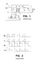
- . Figure 1
- is a circuit diagram of a known flyback converter;
- . Figure 2
- shows voltage and current time plots illustrating operation of the Figure 1 converter;
- . Figure 3
- is a diagram illustrating the use of a tuned tank coil for transferring power between inductors with limited coupling;
- . Figure 4
- is a circuit diagram of a flyback converter provided with a tuning capacitor across its transformer primary winding to cause a ringing effect with the primary leakage inductance of the converter transformer;
- . Figure 5
- shows voltage and current time plots illustrating operation of the Figure 4 converter;
- . Figure 6
- is a simplified equivalent circuit for the transformer and tuning capacitor arrangement of the Figure 4 flyback converter;
- . Figure 7
- is a diagram illustrating the phase response of the Figure 4 circuit as viewed across the transformer primary;
- . Figure 8
- is a circuit diagram of a first form of flyback converter embodying the invention, this converter being provided with tuning capacitors across both its primary and secondary windings and a non-linear device in its output circuit, the non-linear device being constituted by the output circuit diode;
- . Figure 9
- is a simplified equivalent circuit for the transformer and tuning capacitor arrangement of the Figure 8 flyback converter;
- . Figure 10
- is a diagram illustrating the phase response of the Figure 8 circuit as viewed across the transformer primary;
- . Figure 11
- is a diagram illustrating the effect of the non-linear component in the output circuit of the Figure 8 converter;
- . Figure 12
- is a circuit diagram of a second form of flyback converter embodying the invention, this converter being similar to that shown in Figure 8 but with a MOSFET used as the non-linear device in the converter output circuit;
- . Figure 13
- is a circuit diagram of a third form of flyback converter embodying the invention, this converter being similar to that shown in Figure 8 but with turn on of the input-circuit switching device being controlled to occur at minimums of the voltage across the device;
- . Figure 14
- shows voltage and current time plots illustrating operation of the Figure 13 circuit;
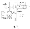
- . Figure 15
- is a circuit diagram of an implementation of the Figure 13 circuit;
- . Figure 16
- is a voltage/time graph showing the voltage across the input-circuit switching device for the Figure 15 circuit but with the secondary tuning capacitor removed;
- . Figure 17
- is a voltage/time graph similar to Figure 16 but with the secondary tuning capacitor connected; and
- . Figure 18
- is a circuit diagram of a variant of the Figure 13 circuit showing a different connection arrangement for the input circuit switching devices.
Claims (11)
- A flyback converter comprising an input circuit (11) coupled to an output circuit (10) through an energy storing transformer (13) that has primary and secondary windings (14,15) each with main and leakage inductances; the input circuit (11) comprising a switching device (16) connected to regulate energisation of said primary winding (14), and control means (17) for controlling the cyclic turning on and off of the switching device (16); and the output circuit (12) comprising a diode (18) connected in series with said secondary winding (15), and a reservoir capacitor (19) connected in parallel with the series combination of the secondary winding (15) and diode (18) and across which the converter output is produced; characterised in that a first tuning capacitance (30) is provided in the input circuit (11) either physically connected in parallel with the primary winding (14) or in a position that in terms of a.c. functional effect is equivalent to such a parallel connection, and in that a second tuning capacitance (35) is provided in the output circuit (12) either physically connected in parallel with said secondary winding (15) or in a position that in terms of a.c. functional effect is equivalent to such a parallel connection, these tuning capacitances (30,35) having values such that:the output circuit including a non-linear device (18;50) operative to combine the anti-phase components of ringing produced by said first and second resonant circuits following turn off of the switching device (16), whereby energy stored in the primary leakage inductance is at least partially transferred to the output circuit (12) and converted into a dc component of the converter output.with the diode (18) in a conducting state a first resonant circuit is formed, with resonant frequency FR, in which the primary leakage inductance and said first tuning capacitance (14) play significant parts, andwith the diode (18) in a non-conducting state a second resonant circuit is formed, with resonant frequency substantially equal to said frequency FR, in which the primary leakage inductance and said second tuning capacitance (35) play significant parts but for which there exists a voltage/current phase relationship either side of resonance that is anti-phase to that for said first resonant circuit;
- A flyback converter according to claim 1, wherein said switching device (16) is a MOSFET and said first tuning capacitance (30) is provided at least in part by the drain-source capacitance (30B) of the MOSFET.
- A flyback converter according to claim 1, wherein said second tuning capacitance (35) is provided at least in part by a capacitor (35A) connected across said diode (18).
- A flyback converter according to claim 1, wherein the converter is provided with multiple said output circuits (12) each coupled to said primary winding (14) through a respective said secondary winding (15) of the transformer (13); said second tuning capacitance (35) being divided between said output circuits (12).
- A flyback converter according to claim 1, wherein said non-linear device is constituted by said diode (18).
- A flyback converter according to claim 1, wherein said non-linear device comprises a MOSFET (50) connected in series with said diode (18), and means (51) for switching the MOSFET (50) on and off at synchronism with said ringing.
- A flyback converter according to claim 1, wherein said control means (17) comprises sensing means (60) for sensing the voltage across the switching device (16) when the latter is off, determining means (61,62) for determining a minimum of the voltage sensed by said sensing means, and turn-on means (64) for turning on the switching device (16) at a said minimum of the voltage thereacross as determined by said determining means.
- A flyback converter according to claim 7, wherein said sensing means comprises a sensing winding (60) wound jointly with said primary and secondary windings (14,15), and said determining means comprises integration means (61) for integrating the voltage sensed by said sensing winding (60), and means (62) for detecting a zero crossing of the voltage integrated by said integration means, this zero crossing being indicative of the said minimum of the voltage across the switching device (16).
- A flyback converter according to claim 7, wherein said control means (17) further comprises means for controlling the duration of the on time of the switching device (16) in dependence on the voltage produced at the output of the converter such as to maintain the converter output voltage substantially constant.
- A flyback converter according to claim 7, wherein said control means (17) further comprises time-out means (65) for initiating turn on of the switching device (16) a predetermined time after when switching device (16) was last on unless the latter is earlier turned on again by said turn-on means (64).
- A flyback converter according to claim 7, wherein said input circuit (11) further comprises an inductor (70) connected in series with said switching device (16), and a capacitor (71) connected in series with said primary winding (14) across the switching device (16).
Priority Applications (6)
| Application Number | Priority Date | Filing Date | Title |
|---|---|---|---|
| AT95410075T ATE173569T1 (en) | 1995-07-31 | 1995-07-31 | FLYBACK CONVERTER |
| EP95410075A EP0757428B1 (en) | 1995-07-31 | 1995-07-31 | Flyback converter |
| DE69506096T DE69506096T2 (en) | 1995-07-31 | 1995-07-31 | Flyback converter |
| US08/675,300 US5608613A (en) | 1995-07-31 | 1996-07-01 | Flyback converter |
| KR1019960030803A KR100398565B1 (en) | 1995-07-31 | 1996-07-27 | Flyback converter |
| JP20047496A JP3652798B2 (en) | 1995-07-31 | 1996-07-30 | Flyback converter |
Applications Claiming Priority (1)
| Application Number | Priority Date | Filing Date | Title |
|---|---|---|---|
| EP95410075A EP0757428B1 (en) | 1995-07-31 | 1995-07-31 | Flyback converter |
Publications (2)
| Publication Number | Publication Date |
|---|---|
| EP0757428A1 EP0757428A1 (en) | 1997-02-05 |
| EP0757428B1 true EP0757428B1 (en) | 1998-11-18 |
Family
ID=8221561
Family Applications (1)
| Application Number | Title | Priority Date | Filing Date |
|---|---|---|---|
| EP95410075A Expired - Lifetime EP0757428B1 (en) | 1995-07-31 | 1995-07-31 | Flyback converter |
Country Status (6)
| Country | Link |
|---|---|
| US (1) | US5608613A (en) |
| EP (1) | EP0757428B1 (en) |
| JP (1) | JP3652798B2 (en) |
| KR (1) | KR100398565B1 (en) |
| AT (1) | ATE173569T1 (en) |
| DE (1) | DE69506096T2 (en) |
Cited By (5)
| Publication number | Priority date | Publication date | Assignee | Title |
|---|---|---|---|---|
| US8023290B2 (en) | 1997-01-24 | 2011-09-20 | Synqor, Inc. | High efficiency power converter |
| US10199950B1 (en) | 2013-07-02 | 2019-02-05 | Vlt, Inc. | Power distribution architecture with series-connected bus converter |
| RU2692466C1 (en) * | 2018-08-17 | 2019-06-25 | Общество с ограниченной ответственностью "Научно-производственная фирма "Плазмаинформ" | Quasi-resonance constant voltage converter with low pulsations of output voltage during operation in conditions of high negative temperatures |
| RU191122U1 (en) * | 2018-07-06 | 2019-07-25 | Общество с ограниченной ответственностью "Научно-производственная фирма "Плазмаинформ" | Quasi-resonant DC voltage converter with low ripple output voltage when operating in conditions of high negative temperatures |
| CN110417288A (en) * | 2019-08-06 | 2019-11-05 | 珠海格力电器股份有限公司 | A kind of novel switched power driving circuit and its control method |
Families Citing this family (40)
| Publication number | Priority date | Publication date | Assignee | Title |
|---|---|---|---|---|
| FR2738418B1 (en) * | 1995-09-01 | 1997-11-21 | Lacme | ELECTRICAL TRANSFORMER DEVICE WHOSE PRIMARY IS SUPPLIED UNDER CONTROL OF A CHOPPER |
| US5822200A (en) * | 1997-04-21 | 1998-10-13 | Nt International, Inc. | Low level, high efficiency DC/DC converter |
| JPH1155943A (en) * | 1997-06-02 | 1999-02-26 | Murata Mfg Co Ltd | Switching power unit |
| IT1308452B1 (en) * | 1999-04-23 | 2001-12-17 | Fiat Ricerche | RESONANT TRANSITION DC-DC CONVERTER AND CONTROL METHOD OF RESONANT TRANSITION OF A DC-DC CONVERTER |
| JP2000324831A (en) * | 1999-05-11 | 2000-11-24 | Sony Corp | Switching power supply circuit |
| US6292069B1 (en) * | 1999-09-14 | 2001-09-18 | Eaton Corporation | Loosely coupled rotary transformer having resonant circuit |
| TW507414B (en) * | 1999-10-29 | 2002-10-21 | Sony Corp | Switching power circuit with secondary side parallel and series resonance |
| US6166926A (en) * | 2000-01-11 | 2000-12-26 | Thomson Licensing S.A. | Zero voltage switching power supply with burst mode |
| US6587358B1 (en) | 2000-05-11 | 2003-07-01 | Sony Corporation | Switching power supply circuit |
| DE60142233D1 (en) | 2000-06-27 | 2010-07-08 | Nxp Bv | COMMUNICATION DEVICE FOR DETERMINING THE ORDER OF PREVIOUS DATA CARRIER |
| US6285567B1 (en) * | 2000-09-14 | 2001-09-04 | Honeywell International Inc. | Methods and apparatus for utilizing the transformer leakage energy in a power supply |
| WO2002039571A1 (en) * | 2000-11-11 | 2002-05-16 | Nmb (U.S.A.), Inc. | Power converter |
| US6341073B1 (en) | 2000-11-16 | 2002-01-22 | Philips Electronics North America Corporation | Multiple valley controller for switching circuit |
| US6421256B1 (en) | 2001-06-25 | 2002-07-16 | Koninklijke Philips Electronics N.V. | Method for reducing mains harmonics and switching losses in discontinuous-mode, switching power converters |
| US6671189B2 (en) * | 2001-11-09 | 2003-12-30 | Minebea Co., Ltd. | Power converter having primary and secondary side switches |
| US6989656B2 (en) * | 2002-05-13 | 2006-01-24 | Jam Technologies, Llc | Flyback converter linearization methods and apparatus |
| EP1437824A1 (en) * | 2003-01-09 | 2004-07-14 | Fabrice Barthélémy | Voltage converter suited for supplying multiple very low security DC-voltages. |
| EP1588588A1 (en) * | 2003-01-14 | 2005-10-26 | Koninklijke Philips Electronics N.V. | Circuit and method for providing power to a load, especially a high-intensity discharge lamp |
| US6995991B1 (en) * | 2004-07-20 | 2006-02-07 | System General Corp. | PWM controller for synchronous rectifier of flyback power converter |
| DE102005028402A1 (en) | 2005-06-20 | 2006-12-21 | Austriamicrosystems Ag | Control arrangement for switching configuration has metal oxide semiconductor field effect transistor (MOSFET) having control connection connected to control circuit output |
| KR100813979B1 (en) * | 2005-07-26 | 2008-03-14 | 삼성전자주식회사 | Power supply device having multiple outputs |
| TW200721653A (en) * | 2005-09-02 | 2007-06-01 | Sony Corp | Switching power supply circuit |
| US20070152642A1 (en) * | 2006-01-03 | 2007-07-05 | Franklin Philip G | Wireless glass-mounted lighting fixtures |
| GB0610422D0 (en) * | 2006-05-26 | 2006-07-05 | Cambridge Semiconductor Ltd | Forward power converters |
| US7738266B2 (en) | 2006-05-26 | 2010-06-15 | Cambridge Semiconductor Limited | Forward power converter controllers |
| KR101009333B1 (en) | 2008-11-18 | 2011-01-19 | 한국전기연구원 | High DC voltage generator and High voltage calibration waveform generator for impulse measurement device |
| US7876584B2 (en) * | 2009-06-24 | 2011-01-25 | Alpha And Omega Semiconductor Incorporated | Circuit and method for controlling the secondary FET of transformer coupled synchronous rectified flyback converter |
| US8964420B2 (en) | 2011-12-13 | 2015-02-24 | Apple Inc. | Zero voltage switching in flyback converters with variable input voltages |
| CN102664526B (en) * | 2012-05-15 | 2015-12-16 | 迈象电子科技(上海)有限公司 | The method of reverse excitation circuit and the loss of reduction reverse excitation circuit transformer leakage inductance |
| TWI496406B (en) * | 2012-07-03 | 2015-08-11 | System General Corp | Power converter and method for controlling power converter |
| US8897038B2 (en) * | 2012-07-31 | 2014-11-25 | Dialog Semiconductor Inc. | Switching power converter dynamic load detection |
| TW201414167A (en) * | 2012-09-26 | 2014-04-01 | Phihong Technology Co Ltd | Controller with quasi-resonant mode and continuous conduction mode and operating method thereof |
| JP5802647B2 (en) * | 2012-12-20 | 2015-10-28 | 株式会社タムラ製作所 | Switching element drive system |
| JP5765591B2 (en) | 2013-04-18 | 2015-08-19 | 株式会社デンソー | Power supply |
| JP5931013B2 (en) * | 2013-07-04 | 2016-06-08 | Fdk株式会社 | Synchronous rectification power supply |
| KR101516088B1 (en) * | 2013-11-28 | 2015-05-06 | 주식회사 포스코아이씨티 | H-Bridge Inverter Module and Multi Level Inverter Using H-Bridge Inverter Module |
| FR3020523B1 (en) * | 2014-04-29 | 2016-05-06 | Valeo Systemes De Controle Moteur | ELECTRICAL POWER SUPPLY AND METHOD FOR CONTROLLING AN ELECTRIC POWER SUPPLY |
| CN104362856B (en) * | 2014-11-05 | 2016-08-24 | 无锡中汇汽车电子科技有限公司 | A kind of control method of Zero-voltage switch flyback changer |
| US10756640B1 (en) * | 2019-03-28 | 2020-08-25 | Appulse Power Inc. | Flyback converter with synchronous rectifier controller |
| CA3185609A1 (en) * | 2020-05-29 | 2021-12-02 | Abl Ip Holding Llc | Flyback converter with indirect estimation of primary-side voltage at the secondary-side |
Family Cites Families (10)
| Publication number | Priority date | Publication date | Assignee | Title |
|---|---|---|---|---|
| US4631652A (en) * | 1984-11-30 | 1986-12-23 | Rca Corporation | Frequency controlled resonant regulator |
| JPS61218368A (en) * | 1985-03-20 | 1986-09-27 | Murata Mfg Co Ltd | Stabilized high voltage power source |
| US4785387A (en) * | 1986-04-28 | 1988-11-15 | Virginia Tech Intellectual Properties, Inc. | Resonant converters with secondary-side resonance |
| US4764857A (en) * | 1987-05-06 | 1988-08-16 | Zenith Electronics Corporation | Power supply start-up circuit with high frequency transformer |
| CA2019525C (en) * | 1989-06-23 | 1995-07-11 | Takuya Ishii | Switching power supply device |
| JPH04217862A (en) * | 1990-01-29 | 1992-08-07 | Toshiba Corp | Current resonance converter |
| US5396410A (en) * | 1990-01-31 | 1995-03-07 | Kabushiki Kaisha Toshiba | Zero current switching resonant converter |
| JPH04150767A (en) * | 1990-10-08 | 1992-05-25 | Fuji Electric Co Ltd | Switching power supply circuit |
| JP3419797B2 (en) * | 1992-01-10 | 2003-06-23 | 松下電器産業株式会社 | Switching power supply |
| JPH06209569A (en) * | 1993-01-05 | 1994-07-26 | Yokogawa Electric Corp | Switching power supply |
-
1995
- 1995-07-31 AT AT95410075T patent/ATE173569T1/en not_active IP Right Cessation
- 1995-07-31 EP EP95410075A patent/EP0757428B1/en not_active Expired - Lifetime
- 1995-07-31 DE DE69506096T patent/DE69506096T2/en not_active Expired - Fee Related
-
1996
- 1996-07-01 US US08/675,300 patent/US5608613A/en not_active Expired - Lifetime
- 1996-07-27 KR KR1019960030803A patent/KR100398565B1/en not_active IP Right Cessation
- 1996-07-30 JP JP20047496A patent/JP3652798B2/en not_active Expired - Fee Related
Cited By (11)
| Publication number | Priority date | Publication date | Assignee | Title |
|---|---|---|---|---|
| US8023290B2 (en) | 1997-01-24 | 2011-09-20 | Synqor, Inc. | High efficiency power converter |
| US8493751B2 (en) | 1997-01-24 | 2013-07-23 | Synqor, Inc. | High efficiency power converter |
| US9143042B2 (en) | 1997-01-24 | 2015-09-22 | Synqor, Inc. | High efficiency power converter |
| US10199950B1 (en) | 2013-07-02 | 2019-02-05 | Vlt, Inc. | Power distribution architecture with series-connected bus converter |
| US10594223B1 (en) | 2013-07-02 | 2020-03-17 | Vlt, Inc. | Power distribution architecture with series-connected bus converter |
| US11075583B1 (en) | 2013-07-02 | 2021-07-27 | Vicor Corporation | Power distribution architecture with series-connected bus converter |
| US11705820B2 (en) | 2013-07-02 | 2023-07-18 | Vicor Corporation | Power distribution architecture with series-connected bus converter |
| RU191122U1 (en) * | 2018-07-06 | 2019-07-25 | Общество с ограниченной ответственностью "Научно-производственная фирма "Плазмаинформ" | Quasi-resonant DC voltage converter with low ripple output voltage when operating in conditions of high negative temperatures |
| RU2692466C1 (en) * | 2018-08-17 | 2019-06-25 | Общество с ограниченной ответственностью "Научно-производственная фирма "Плазмаинформ" | Quasi-resonance constant voltage converter with low pulsations of output voltage during operation in conditions of high negative temperatures |
| CN110417288A (en) * | 2019-08-06 | 2019-11-05 | 珠海格力电器股份有限公司 | A kind of novel switched power driving circuit and its control method |
| CN110417288B (en) * | 2019-08-06 | 2021-01-15 | 珠海格力电器股份有限公司 | Novel switching power supply driving circuit and control method thereof |
Also Published As
| Publication number | Publication date |
|---|---|
| DE69506096T2 (en) | 1999-04-15 |
| KR970008238A (en) | 1997-02-24 |
| KR100398565B1 (en) | 2004-04-14 |
| JP3652798B2 (en) | 2005-05-25 |
| JPH09107676A (en) | 1997-04-22 |
| US5608613A (en) | 1997-03-04 |
| DE69506096D1 (en) | 1998-12-24 |
| ATE173569T1 (en) | 1998-12-15 |
| EP0757428A1 (en) | 1997-02-05 |
Similar Documents
| Publication | Publication Date | Title |
|---|---|---|
| EP0757428B1 (en) | Flyback converter | |
| US6061252A (en) | Switching power supply device | |
| JP3475925B2 (en) | Switching power supply | |
| CN103178719B (en) | Multi-voltage power supply | |
| JP3475887B2 (en) | Switching power supply | |
| EP0658968B1 (en) | Switching regulator | |
| US8817497B2 (en) | Switching power converter for reducing EMI from ring oscillation and its control method | |
| US7295449B2 (en) | Simple switched-mode power supply with current and voltage limitation | |
| TWI732581B (en) | Conversion device with oscillation reduction control and method of operation of oscillation reduction control the same | |
| JP2002084753A (en) | Multiple-output switching power supply unit | |
| JP3653075B2 (en) | Switching power transmission device | |
| EP1032968B1 (en) | Switched-mode power supply | |
| CA2307441A1 (en) | Zero voltage switched power supply converter | |
| US6975097B2 (en) | Unitary magnetic coupler and switch mode power supply | |
| CA2214217C (en) | Switching power supply apparatus | |
| CN112072922B (en) | Conversion device with shock absorption control and operation method of shock absorption control thereof | |
| JP4253808B2 (en) | Switching power supply | |
| GB2456599A (en) | Resonant discontinuous forward power converter | |
| CA2220747A1 (en) | Dc-dc converters | |
| KR19990065926A (en) | Lossless snubber circuit for soft switching of booster AC / DC converters and full bridge DC / DC converters | |
| AU737397B2 (en) | Lossless active clamp for secondary circuits | |
| KR100258755B1 (en) | Apparatus for power supply in isdn network terminal | |
| JPH1066335A (en) | Converter circuit | |
| KR20040031503A (en) | Snuber circuit and Switching Mode Power Supply thereof | |
| JP2006304471A (en) | Self-excited type switching power supply device |
Legal Events
| Date | Code | Title | Description |
|---|---|---|---|
| PUAI | Public reference made under article 153(3) epc to a published international application that has entered the european phase |
Free format text: ORIGINAL CODE: 0009012 |
|
| AK | Designated contracting states |
Kind code of ref document: A1 Designated state(s): AT DE FR GB IT NL SE |
|
| 17P | Request for examination filed |
Effective date: 19970714 |
|
| 17Q | First examination report despatched |
Effective date: 19971020 |
|
| GRAG | Despatch of communication of intention to grant |
Free format text: ORIGINAL CODE: EPIDOS AGRA |
|
| GRAG | Despatch of communication of intention to grant |
Free format text: ORIGINAL CODE: EPIDOS AGRA |
|
| GRAH | Despatch of communication of intention to grant a patent |
Free format text: ORIGINAL CODE: EPIDOS IGRA |
|
| GRAH | Despatch of communication of intention to grant a patent |
Free format text: ORIGINAL CODE: EPIDOS IGRA |
|
| GRAH | Despatch of communication of intention to grant a patent |
Free format text: ORIGINAL CODE: EPIDOS IGRA |
|
| GRAA | (expected) grant |
Free format text: ORIGINAL CODE: 0009210 |
|
| AK | Designated contracting states |
Kind code of ref document: B1 Designated state(s): AT DE FR GB IT NL SE |
|
| PG25 | Lapsed in a contracting state [announced via postgrant information from national office to epo] |
Ref country code: SE Free format text: THE PATENT HAS BEEN ANNULLED BY A DECISION OF A NATIONAL AUTHORITY Effective date: 19981118 Ref country code: AT Free format text: LAPSE BECAUSE OF FAILURE TO SUBMIT A TRANSLATION OF THE DESCRIPTION OR TO PAY THE FEE WITHIN THE PRESCRIBED TIME-LIMIT Effective date: 19981118 |
|
| REF | Corresponds to: |
Ref document number: 173569 Country of ref document: AT Date of ref document: 19981215 Kind code of ref document: T |
|
| REF | Corresponds to: |
Ref document number: 69506096 Country of ref document: DE Date of ref document: 19981224 |
|
| ET | Fr: translation filed | ||
| PLBE | No opposition filed within time limit |
Free format text: ORIGINAL CODE: 0009261 |
|
| STAA | Information on the status of an ep patent application or granted ep patent |
Free format text: STATUS: NO OPPOSITION FILED WITHIN TIME LIMIT |
|
| 26N | No opposition filed | ||
| REG | Reference to a national code |
Ref country code: GB Ref legal event code: 732E |
|
| NLS | Nl: assignments of ep-patents |
Owner name: HEWLETT-PACKARD COMPANY (A DELAWARE CORPORATION) |
|
| REG | Reference to a national code |
Ref country code: GB Ref legal event code: IF02 |
|
| REG | Reference to a national code |
Ref country code: FR Ref legal event code: TP |
|
| PGFP | Annual fee paid to national office [announced via postgrant information from national office to epo] |
Ref country code: DE Payment date: 20070831 Year of fee payment: 13 |
|
| PGFP | Annual fee paid to national office [announced via postgrant information from national office to epo] |
Ref country code: GB Payment date: 20070727 Year of fee payment: 13 |
|
| PGFP | Annual fee paid to national office [announced via postgrant information from national office to epo] |
Ref country code: NL Payment date: 20070724 Year of fee payment: 13 Ref country code: IT Payment date: 20070727 Year of fee payment: 13 |
|
| PGFP | Annual fee paid to national office [announced via postgrant information from national office to epo] |
Ref country code: FR Payment date: 20070717 Year of fee payment: 13 |
|
| GBPC | Gb: european patent ceased through non-payment of renewal fee |
Effective date: 20080731 |
|
| NLV4 | Nl: lapsed or anulled due to non-payment of the annual fee |
Effective date: 20090201 |
|
| PG25 | Lapsed in a contracting state [announced via postgrant information from national office to epo] |
Ref country code: DE Free format text: LAPSE BECAUSE OF NON-PAYMENT OF DUE FEES Effective date: 20090203 |
|
| REG | Reference to a national code |
Ref country code: FR Ref legal event code: ST Effective date: 20090331 |
|
| PG25 | Lapsed in a contracting state [announced via postgrant information from national office to epo] |
Ref country code: NL Free format text: LAPSE BECAUSE OF NON-PAYMENT OF DUE FEES Effective date: 20090201 |
|
| PG25 | Lapsed in a contracting state [announced via postgrant information from national office to epo] |
Ref country code: GB Free format text: LAPSE BECAUSE OF NON-PAYMENT OF DUE FEES Effective date: 20080731 |
|
| PG25 | Lapsed in a contracting state [announced via postgrant information from national office to epo] |
Ref country code: IT Free format text: LAPSE BECAUSE OF NON-PAYMENT OF DUE FEES Effective date: 20080731 Ref country code: FR Free format text: LAPSE BECAUSE OF NON-PAYMENT OF DUE FEES Effective date: 20080731 |