EP0752343A2 - Monitor fixation device in a vehicle - Google Patents
Monitor fixation device in a vehicle Download PDFInfo
- Publication number
- EP0752343A2 EP0752343A2 EP96106505A EP96106505A EP0752343A2 EP 0752343 A2 EP0752343 A2 EP 0752343A2 EP 96106505 A EP96106505 A EP 96106505A EP 96106505 A EP96106505 A EP 96106505A EP 0752343 A2 EP0752343 A2 EP 0752343A2
- Authority
- EP
- European Patent Office
- Prior art keywords
- holding
- monitor
- housing
- channel
- rail
- Prior art date
- Legal status (The legal status is an assumption and is not a legal conclusion. Google has not performed a legal analysis and makes no representation as to the accuracy of the status listed.)
- Ceased
Links
Images
Classifications
-
- B—PERFORMING OPERATIONS; TRANSPORTING
- B60—VEHICLES IN GENERAL
- B60R—VEHICLES, VEHICLE FITTINGS, OR VEHICLE PARTS, NOT OTHERWISE PROVIDED FOR
- B60R11/00—Arrangements for holding or mounting articles, not otherwise provided for
- B60R11/02—Arrangements for holding or mounting articles, not otherwise provided for for radio sets, television sets, telephones, or the like; Arrangement of controls thereof
- B60R11/0229—Arrangements for holding or mounting articles, not otherwise provided for for radio sets, television sets, telephones, or the like; Arrangement of controls thereof for displays, e.g. cathodic tubes
-
- B—PERFORMING OPERATIONS; TRANSPORTING
- B60—VEHICLES IN GENERAL
- B60R—VEHICLES, VEHICLE FITTINGS, OR VEHICLE PARTS, NOT OTHERWISE PROVIDED FOR
- B60R11/00—Arrangements for holding or mounting articles, not otherwise provided for
- B60R2011/0001—Arrangements for holding or mounting articles, not otherwise provided for characterised by position
- B60R2011/0003—Arrangements for holding or mounting articles, not otherwise provided for characterised by position inside the vehicle
- B60R2011/0028—Ceiling, e.g. roof rails
-
- B—PERFORMING OPERATIONS; TRANSPORTING
- B60—VEHICLES IN GENERAL
- B60R—VEHICLES, VEHICLE FITTINGS, OR VEHICLE PARTS, NOT OTHERWISE PROVIDED FOR
- B60R11/00—Arrangements for holding or mounting articles, not otherwise provided for
- B60R2011/0042—Arrangements for holding or mounting articles, not otherwise provided for characterised by mounting means
- B60R2011/0049—Arrangements for holding or mounting articles, not otherwise provided for characterised by mounting means for non integrated articles
- B60R2011/0078—Quick-disconnect two-parts mounting means
Definitions
- the invention relates to a fastening device for a monitor in a vehicle according to the type specified in the preamble of claim 1.
- monitors serving the broadcasting of entertainment programs and information programs.
- the monitor is often installed above the entrance area or above the aisles of the vehicle.
- a new regulation requires a certain headroom for passengers in the vehicle.
- brackets that reduce the distance between the top of the monitor housing and the holding device attached to the vehicle roof, in order to be able to maintain the prescribed headroom in the vehicle even when using a 15-inch screen.
- Such a generic solution known from DE-GM 9304257 consists of a holding device with two strips serving as holding parts, each of which is provided with a stepped part. There are recesses in two places on the housing of the monitor which, when the monitor is installed, allow the detached part of the strips to enter the monitor housing and the monitor frame to be pushed in via the strip projections. The offset parts must be inserted into the recesses at the same time. This installation procedure inevitably has the consequence that the electrical connections between the monitor and the holding devices have to be made simultaneously with the insertion of the monitor housing via the ledge projections.
- a plug part is fixedly attached to a strip, which automatically slides into a second plug part attached to the monitor when the monitor is inserted into the holding device attached to the roof structure of the vehicle.
- a disadvantage here is that the plug part must be made very precisely in order to enable problem-free, precisely fitting insertion of the monitor.
- the monitor housing must be additionally secured by a further holding member after insertion into the two strips in order to prevent it from slipping out of the holding device. When removing the monitor, the fastening means of the additional holding member must first be released again before the monitor can be pulled out of the strips.
- Another serious disadvantage of the prior art consists in the recesses in the monitor housing that accommodate the strips. An open monitor housing means that dust and dirt particles through the Openings can penetrate into the monitor and lead to short circuits in the sensitive electronic components of the monitor.
- the device according to the invention for fastening a monitor according to the characterizing features of claim 1 has the advantage that the monitor housing is first attached to the corresponding holding part of the holding device attached to the roof structure of the vehicle only with the first holding member.
- the fitter now has both hands free and enough space to subsequently establish the electrical connection between the monitor, which can be freely pivoted about an axis, and the holding device. Only then is the monitor housing pivoted towards the second holding part and fastened with the second holding member to the second holding part of the holding device.
- the monitor is now firmly attached in the prescribed position, so that an additional attachment by another holding part is unnecessary.
- Another advantage achieved with the invention is in particular that a closed monitor housing is used which prevents the penetration of dirt particles into the monitor.
- the rail of the monitor housing provided as a holding member can additionally be secured in position by a further connecting means.
- the further design of the rail provided in claims 6 and 10 give the monitor housing particular stability.
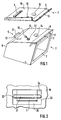
- the device for fastening a monitor shown in FIG. 1 consists of a holding device 1 and a monitor housing 2 which can be connected to it, including a screen opening 7, an upper side 8 and a rear side 9.
- the holding device 1 which is attached to the roof structure of a vehicle and there is a carrier part 19 designed as a plate, has a first holding part 3 and a second holding part 4.
- the first holding part 3 is formed as a bent stamped part from the carrier part and forms one for the roof structure of the vehicle open channel.
- the channel 3, with its one long side facing away from the screen opening 7, is in one piece with the carrier part and, at least on its other long side, leaves a distance 25 to the cutout 23 of the carrier part, as shown in FIG.
- the second holding part 4 is arranged as a surface 4, which runs parallel to the trough and is mutually angled twice, as a sheet metal part which extends over the width of the monitor at the end of the carrier part 19 opposite the trough.
- the monitor housing 2 has a first holding member 5 and a second holding member 6 on its upper side 8.
- the first holding member 5 is designed as a bracket, consisting of a rod part 21 parallel to the upper side 8 of the monitor housing and two lateral, adjoining holding arms 22 which project vertically from the monitor and which, viewed from the screen opening, are fastened to the rear transition area between the rear wall 9 and the upper side 8 are.
- the second holding member which is designed as a rail 6 which is angled twice alternately. The rail is firmly connected to the monitor housing with one of its angled longitudinal sides.
- the monitor housing is pushed with the bracket through the distance 25 between the channel and the support part 19 and suspended with the rod part 21 in the channel 3 of the support part fastened to the roof structure, the two lateral holding arms 22 projecting vertically from the monitor housing by the distance 24 between the broadside grip the groove and the cutout 23 of the support part and thereby prevent longitudinal movement of the bracket in the groove.
- the housing is then pivotable about an axis of rotation, which is determined by channel 3 and bracket 5.
- a cable protruding from a recess 17 on the housing top 8 can be connected to a electrical connector part 16 are inserted into a further socket part 15, which is fastened to the carrier part 19.
- the monitor housing When the monitor housing is pivoted in the direction of the carrier part, the electrical cables dip into the recess 17 on the top of the housing.
- the monitor housing is pivoted in the direction of the carrier part until a first spherical shell-shaped stop part 13 located on the underside of the carrier part and a second spherical shell-shaped stop part 14 located on the upper side of the monitor housing touch each other.
- latching means 10 and 11 which are assigned to one another and which are located on the rail 6 on the one hand and the sheet metal part forming the surface 4 on the other hand, snap into one another, so that the monitor is now firmly fastened to the carrier part with both holding members.
- the rail 6, on the one angled side of which there are screws 12 is screwed to the surface 4.
Abstract
Description
Die Erfindung geht von einer Befestigungsvorrichtung für einen Monitor in einem Fahrzeug nach der im Oberbegriff des Anspruchs 1 angegebenen Gattung aus. In großräumigen, der Personenbeförderung dienenden Fahrzeugen ist es bereits seit längerem üblich, der Ausstrahlung von Unterhaltungsprogrammen und Informationssendungen diendende Monitore zu verwenden. Es ist zweckmäßig, einen Monitor mit einem 15-Zoll-Bildschirm an der Dachkonstruktion des Fahrzeuges zu befestigen, damit auch weiter entfernt sitzenden Passagieren die Sicht auf das Monitorbild ermöglicht wird. Oft wird der Monitor aus Platzgründen über dem Eingangsbereich oder über den Gängen des Fahrzeuges angebracht. Eine neue Vorschrift verlangt dabei eine bestimmte Durchgangshöhe für die Passagiere im Fahrzeug. Es ist bekannt, zur Befestigung des Monitors im Fahrzeug eine Haltevorrichtung an der Dachkonstruktion anzubringen, die mit dem Monitor verbunden werden kann. Es ist ferner bekannt, dabei Halterungen zu verwenden, die den Abstand zwischen der Oberseite des Monitorgehäuses und der am Fahrzeugdach befestigten Haltevorrichtung verkleinern, um die vorgeschriebene Durchgangshöhe im Fahrzeug auch bei Verwendung eines 15-Zoll-Bildschirmes einhalten zu können.The invention relates to a fastening device for a monitor in a vehicle according to the type specified in the preamble of claim 1. In large-scale vehicles used for the transport of people, it has long been customary to use monitors serving the broadcasting of entertainment programs and information programs. It is advisable to attach a monitor with a 15-inch screen to the roof structure of the vehicle so that passengers sitting further away can see the monitor image. For reasons of space, the monitor is often installed above the entrance area or above the aisles of the vehicle. A new regulation requires a certain headroom for passengers in the vehicle. It is known to attach a holding device to the roof structure for fastening the monitor in the vehicle, which can be connected to the monitor. It is also known to use brackets that reduce the distance between the top of the monitor housing and the holding device attached to the vehicle roof, in order to be able to maintain the prescribed headroom in the vehicle even when using a 15-inch screen.
Eine solche durch die DE-GM 9304257 bekannte, gattungsgemäße Lösung besteht aus einer Haltevorrichtung mit zwei als Halteteile dienenden Leisten, die jeweils mit einem abgesetzten Teil versehen sind. Am Gehäuse des Monitors befinden sich an zwei Stellen Ausnehmungen, die bei Einbau des Monitors den Eintritt des abgesetzten Teiles der Leisten in das Monitorgehäuse und ein Einschieben des Monitorrahmens über die Leistenvorsprünge ermöglichen. Dabei müssen die abgesetzten Teile zugleich in die Ausnehmungen eingeführt werden. Dieses Einbauverfahren hat zwangsläufig zur Folge, daß gleichzeitig mit dem Einschieben des Monitorgehäuses über die Leistenvorsprünge, die elektrischen Verbindungen zwischen Monitor und Haltevorrichtungen hergestellt werden müssen. Aus diesem Grund wird an einer Leiste ein Steckerteil fest angebracht, welches sich beim Einsetzen des Monitors in die an der Dachkonstruktion des Fahrzeuges angebrachte Haltevorrichtung automatisch in ein am Monitor angebrachtes zweites Steckerteil einschiebt. Als nachteilig ist hierbei anzusehen, daß das Steckerteil sehr präzise gefertigt sein muß, um ein problemloses, paßgenaues Einsetzen des Monitors zu ermöglichen. Außerdem werden die elektrischen Anschlüsse bei häufigem Ein- und Ausbau des Monitors durch die Befestigung an den Leisten stark beansprucht und verschleißen schneller. Weiterhin muß als nachteilig angesehen werden, daß das Monitorgehäuse nach Einsetzen in die beiden Leisten zusätzlich durch ein weiteres Halteglied gesichert werden muß, um ein Herausrutschen aus der Haltevorrichtung zu verhindern. Bei Ausbau des Monitors muß das Befestigungsmittel des zusätzlichen Haltegliedes erst wieder gelöst werden, bevor der Monitor aus den Leisten herausgezogen werden kann. Ein weiterer gravierender Nachteil des bisherigen Standes der Technik besteht in den der Aufnahme der Leisten diendenen Ausnehmungen des Monitorgehäuses. Ein offenes Monitorgehäuse hat zur Folge, daß Staub und Schmutzpartikel durch die Öffnungen in den Monitor eindringen und zu Kurzschlüssen in den empfindlichen elektronischen Bauelementen des Monitors führen können.Such a generic solution known from DE-GM 9304257 consists of a holding device with two strips serving as holding parts, each of which is provided with a stepped part. There are recesses in two places on the housing of the monitor which, when the monitor is installed, allow the detached part of the strips to enter the monitor housing and the monitor frame to be pushed in via the strip projections. The offset parts must be inserted into the recesses at the same time. This installation procedure inevitably has the consequence that the electrical connections between the monitor and the holding devices have to be made simultaneously with the insertion of the monitor housing via the ledge projections. For this reason, a plug part is fixedly attached to a strip, which automatically slides into a second plug part attached to the monitor when the monitor is inserted into the holding device attached to the roof structure of the vehicle. A disadvantage here is that the plug part must be made very precisely in order to enable problem-free, precisely fitting insertion of the monitor. In addition, if the monitor is installed and removed frequently, the electrical connections are heavily used due to the attachment to the strips and wear out faster. Furthermore, it must be regarded as a disadvantage that the monitor housing must be additionally secured by a further holding member after insertion into the two strips in order to prevent it from slipping out of the holding device. When removing the monitor, the fastening means of the additional holding member must first be released again before the monitor can be pulled out of the strips. Another serious disadvantage of the prior art consists in the recesses in the monitor housing that accommodate the strips. An open monitor housing means that dust and dirt particles through the Openings can penetrate into the monitor and lead to short circuits in the sensitive electronic components of the monitor.
Die erfindungsgemäße Vorrichtung zur Befestigung eines Monitors nach den kennzeichnenden Merkmalen des Anspruchs 1 hat demgegenüber den Vorteil, daß das Monitorgehäuse zunächst nur mit dem ersten Halteglied an dem entsprechenden Halteteil der an der Dachkonstruktion des Fahrzeuges angebrachten Haltevorrichtung befestigt wird. Der Monteur hat nun beide Hände frei und genügend Platz, um anschließend die elektrischen Verbindung zwischen dem um eine Achse frei schwenkbaren Monitor und der Haltevorrichtung herzustellen. Erst dann wird das Monitorgehäuse zum zweiten Halteteil hingeschwenkt und mit dem zweiten Halteglied am zweiten Halteteil der Haltevorrichtung befestigt. Der Monitor ist nun fest in der vorgeschriebenen Position angebracht, so daß eine zusätzliche Befestigung durch ein weiteres Halteteil unnötig ist. Ein weiterhin mit der Erfindung erzielter Vorteil besteht insbesondere darin, daß ein geschlossenes Monitorgehäuse verwendet wird, welches das Eindringen von Schmutzpartikeln in den Monitor verhindert.The device according to the invention for fastening a monitor according to the characterizing features of claim 1 has the advantage that the monitor housing is first attached to the corresponding holding part of the holding device attached to the roof structure of the vehicle only with the first holding member. The fitter now has both hands free and enough space to subsequently establish the electrical connection between the monitor, which can be freely pivoted about an axis, and the holding device. Only then is the monitor housing pivoted towards the second holding part and fastened with the second holding member to the second holding part of the holding device. The monitor is now firmly attached in the prescribed position, so that an additional attachment by another holding part is unnecessary. Another advantage achieved with the invention is in particular that a closed monitor housing is used which prevents the penetration of dirt particles into the monitor.
Vorteilhafte Ausgestaltungen der Erfindung sind in den Unteransprüchen 2 bis 10 angegeben. Die Weiterbildung nach Anspruch 2 und 9 ermöglicht ein einfaches Einhängen des Monitorgehäuses in die als Stanzbiegeteil ausgeformte Rinne des Trägerteils. Das nach Anspruch 9 als stabiler Bügel mit zwei seitlichen Haltearmen ausgebildete Halteglied des Monitorgehäuses verhindert dabei eine ungewollte seitliche Verschiebung des in der Rinne pendelnden Monitors, so daß das Monitorgehäuse in dieser Position nur noch durch eine anhebende Bewegung aus der Rinne des Trägerteils ausgehängt werden kann. Nach Herstellung der elektrischen Verbindungen kann der Monitor nun frei in Richtung des Trägerteils geschwenkt werden, bis ein in Schwenkrichtung wirksames Rastmittel nach Anspruch 3 betätigt wird, so daß der Monitor fest am Trägerteil verankert ist. Um ein durch eine versehentliche erneute Betätigung des Rastmittels ausgelöstes Zurückschwenken des Monitors zu verhindern, kann die als Halteglied vorgesehene Schiene des Monitorgehäuses zusätzlich nach Anspruch 4 und 5 durch ein weiteres Verbindungsmittel in seiner Position gesichert werden. Die in Anspruch 6 und 10 vorgesehene weitere Ausgestaltung der Schiene verleihen dem Monitorgehäuse besondere Stabilität.Advantageous embodiments of the invention are specified in
Ein Ausführungsbeispiel der Erfindung ist in der Zeichnung dargestellt und wird in der nachfolgenden Beschreibung näher erläutert. Es zeigt
- Figur 1 eine perspektivische Darstellung von Haltevorrichtung und Monitorgehäuse,
Figur 2 eine Draufsicht auf die aus dem Trägerteil geformte Rinne, in welche der Bügel des Monitorgehäuses eingehängt ist.
- FIG. 1 shows a perspective view of the holding device and monitor housing,
- Figure 2 is a plan view of the channel formed from the carrier part, in which the bracket of the monitor housing is suspended.
Die in der Figur 1 dargestellte Vorrichtung zur Befestigung eines Monitors besteht aus einer Haltevorrichtung 1 und einem damit verbindbaren Monitorgehäuse 2 mit unter anderem einer Bildschirmöffnung 7, einer Oberseite 8 und einer Rückseite 9. Die Haltevorrichtung 1, die aus einem an der Dachkonstruktion eines Fahrzeuges angebrachten und als Platte ausgebildeten Trägerteil 19 besteht, weist ein erstes Halteteil 3 und ein zweites Halteteil 4 auf. Das erste Halteteil 3 ist als Biegestanzteil aus dem Trägerteil geformt und bildet eine zur Dachkonstruktion des Fahrzeuges hin offene Rinne. Dabei ist die Rinne 3 mit ihrer einen von der Bildschirmöffnung 7 abgewandten Längsseite einstückig mit dem Trägerteil und läßt zumindest an ihrer anderen Längsseite, wie in Figur 2 dargestellt, einen Abstand 25 zum Ausschnitt 23 des Trägerteils frei. Das zweite Halteteil 4 ist als eine zur Rinne parallel verlaufende, zweimal wechselseitig abgewinkelte Fläche 4 als über die Breite des Monitors sich erstreckendes Blechteil an dem der Rinne gegenüberliegenden Ende des Trägerteils 19 angeordnet. Das Monitorgehäuse 2 weist an seiner Oberseite 8 ein erstes Halteglied 5 und ein zweites Halteglied 6 auf. Das erste Halteglied 5 ist als Bügel ausgebildet, bestehend aus einem zur Oberseite 8 des Monitorgehäuses parallelen Stangenteil 21 und zwei seitlichen, sich anschließenden, vom Monitor senkrecht abstehenden Haltearmen 22, die von der Bildschirmöffnung aus gesehen am hinteren Übergangsbereich zwischen Rückwand 9 und Oberseite 8 befestigt sind. An dem Ende der Oberseite 8, welches der Bildschirmöffnung 7 zugewandt ist, befindet sich das zweite Halteglied, welches als zweimal wechselseitig abgewinkelte Schiene 6 ausgebildet ist. Die Schiene ist mit einer ihrer abgewinkelten Längseiten fest mit dem Monitorgehäuse verbunden.The device for fastening a monitor shown in FIG. 1 consists of a holding device 1 and a
Das Monitorgehäuse wird mit dem Bügel durch den Abstand 25 zwischen Rinne und Trägerteil 19 geschoben und mit dem Stangenteil 21 in die Rinne 3 des an der Dachkonstruktion befestigten Trägerteils eingehängt, wobei die zwei seitlichen vom Monitorgehäuse senkrecht abstehenden Haltearme 22 durch den Abstand 24 zwischen der Breitseite der Rinne und dem Ausschnitt 23 des Trägerteils greifen und dadurch eine längsseitige Verschiebung des Bügels in der Rinne verhindern. In dieser Position ist das Gehäuse dann um eine Drehachse, welche durch Rinne 3 und Bügel 5 bestimmt ist, schwenkbar. Zur Herstellung einer elektrischen Verbindungen zum Monitor kann ein aus einer Ausnehmung 17 an der Gehäuseoberseite 8 herausragendes Kabel mit einem elektrischen Steckerteil 16 in ein weiteres Buchsenteil 15, welches am Trägerteil 19 befestigt ist, eingesteckt werden. Beim Schwenken des Monitorgehäuses in Richtung des Trägerteils tauchen die elektrischen Kabel in die Ausnehmung 17 an der Gehäuseoberseite ein. Das Monitorgehäuse wird so weit in Richtung des Trägerteils geschwenkt, bis ein erstes an der Unterseite des Trägerteils befindliches kugelschalenförmiges Anschlagteil 13 und ein zweites an der Oberseite des Monitorgehäuses befindliches kugelschalenförmiges Anschlagteil 14 einander berühren. Spätestens in dieser Position rasten einander zugeordnete Rastmittel 10 und 11, welche sich an der Schiene 6 einerseits und dem die Fläche 4 bildenden Blechteil andererseits befinden, ineinander ein, so daß der Monitor nun mit beiden Haltegliedern fest am Trägerteil befestigt ist. Als zusätzliche Sicherung, welche ein Zurückschwingen des Monitors aufgrund einer versehentlichen Betätigung der Rastmittel verhindert, wird die Schiene 6, an deren einer abgewinkelten Seite sich Schrauben 12 befinden, mit der Fläche 4 verschraubt.The monitor housing is pushed with the bracket through the
Claims (10)
Applications Claiming Priority (2)
| Application Number | Priority Date | Filing Date | Title |
|---|---|---|---|
| DE29510797U | 1995-07-04 | ||
| DE29510797U DE29510797U1 (en) | 1995-07-04 | 1995-07-04 | Device for mounting a monitor in a vehicle |
Publications (2)
| Publication Number | Publication Date |
|---|---|
| EP0752343A2 true EP0752343A2 (en) | 1997-01-08 |
| EP0752343A3 EP0752343A3 (en) | 1997-05-21 |
Family
ID=8010097
Family Applications (1)
| Application Number | Title | Priority Date | Filing Date |
|---|---|---|---|
| EP96106505A Ceased EP0752343A3 (en) | 1995-07-04 | 1996-04-25 | Monitor fixation device in a vehicle |
Country Status (2)
| Country | Link |
|---|---|
| EP (1) | EP0752343A3 (en) |
| DE (1) | DE29510797U1 (en) |
Cited By (2)
| Publication number | Priority date | Publication date | Assignee | Title |
|---|---|---|---|---|
| DE19938690A1 (en) * | 1999-08-14 | 2001-02-15 | Volkswagen Ag | Fold-out monitor for instrument panel of motor vehicles is contained in holder within panel, module, and has a folding/slide mechanism with crank guide and drive motor |
| EP2371627A1 (en) * | 2009-11-16 | 2011-10-05 | Qingdao Sifang Rolling Stock Research Institute Co., Ltd. | Onboard tv for railway vehicle |
Families Citing this family (1)
| Publication number | Priority date | Publication date | Assignee | Title |
|---|---|---|---|---|
| JP3759723B2 (en) | 2002-05-16 | 2006-03-29 | 三菱電機株式会社 | Temporary fixing structure for electronic equipment |
Citations (3)
| Publication number | Priority date | Publication date | Assignee | Title |
|---|---|---|---|---|
| US4180299A (en) * | 1978-04-17 | 1979-12-25 | Tolerson Lawrence E | Carrier |
| DE8906034U1 (en) * | 1989-05-16 | 1989-08-10 | Rose & Holiet Gmbh, 3052 Bad Nenndorf, De | |
| DE9304257U1 (en) * | 1993-03-22 | 1993-06-24 | Rose & Holiet Gmbh, 3052 Bad Nenndorf, De |
-
1995
- 1995-07-04 DE DE29510797U patent/DE29510797U1/en not_active Expired - Lifetime
-
1996
- 1996-04-25 EP EP96106505A patent/EP0752343A3/en not_active Ceased
Patent Citations (3)
| Publication number | Priority date | Publication date | Assignee | Title |
|---|---|---|---|---|
| US4180299A (en) * | 1978-04-17 | 1979-12-25 | Tolerson Lawrence E | Carrier |
| DE8906034U1 (en) * | 1989-05-16 | 1989-08-10 | Rose & Holiet Gmbh, 3052 Bad Nenndorf, De | |
| DE9304257U1 (en) * | 1993-03-22 | 1993-06-24 | Rose & Holiet Gmbh, 3052 Bad Nenndorf, De |
Cited By (4)
| Publication number | Priority date | Publication date | Assignee | Title |
|---|---|---|---|---|
| DE19938690A1 (en) * | 1999-08-14 | 2001-02-15 | Volkswagen Ag | Fold-out monitor for instrument panel of motor vehicles is contained in holder within panel, module, and has a folding/slide mechanism with crank guide and drive motor |
| DE19938690B4 (en) * | 1999-08-14 | 2008-07-10 | Volkswagen Ag | Fold-out monitor |
| EP2371627A1 (en) * | 2009-11-16 | 2011-10-05 | Qingdao Sifang Rolling Stock Research Institute Co., Ltd. | Onboard tv for railway vehicle |
| EP2371627A4 (en) * | 2009-11-16 | 2012-05-09 | Qingdao Sifang Sri | Onboard tv for railway vehicle |
Also Published As
| Publication number | Publication date |
|---|---|
| DE29510797U1 (en) | 1996-11-21 |
| EP0752343A3 (en) | 1997-05-21 |
Similar Documents
| Publication | Publication Date | Title |
|---|---|---|
| DE60217159T2 (en) | ELECTRICAL INSTALLATION JACK WITH DEEP FRONT PANEL | |
| DE60004357T2 (en) | FASTENING BRACKET FOR A MODULE CARRIER AND DEVICE AND METHOD FOR MOUNTING A MODULE IN A MODULE CARRIER | |
| DE19511464C2 (en) | Device for holding and guiding cables and hoses in control cabinets | |
| EP0244582B1 (en) | Fittings for furniture construction | |
| DE60106194T2 (en) | SERVICE DEVICE | |
| EP1064707A1 (en) | Frame for a switch cabinet | |
| DE3446191A1 (en) | BRACKET FOR A SPEAKER IN A SURFACE OF A VEHICLE | |
| DE19902533A1 (en) | Tamper resistant raceway cover | |
| EP0723752B1 (en) | Connecting fitting to connect a drawer rail to a rear or side wall of a drawer | |
| EP0144605B1 (en) | Display with a rotating screen casing | |
| DE69912049T2 (en) | Mounting device for the door handle of a vehicle door | |
| DE3521089C2 (en) | Device for fastening and removing vehicle equipment | |
| DE3113679A1 (en) | Installation apparatus box for installation in installation channels (ducts) | |
| DE3709069A1 (en) | WIRE FASTENING DEVICE FOR A WINDOW REGULATING DEVICE | |
| DE102013108807B4 (en) | Fastening device for vehicle equipment | |
| DE1925350A1 (en) | Clamp for assembling equipment on perforated plates | |
| DE3726200C2 (en) | ||
| AT13583U1 (en) | Mounting part for a railing | |
| DE102006037280B4 (en) | Electricity meter plate and quick assembly kit | |
| AT402120B (en) | DISPLAY DEVICE | |
| DE3325681A1 (en) | ELECTRICAL APPARATUS PANEL ASSEMBLY AND PROVIDED FASTENING ANGLE | |
| AT399261B (en) | FRONT PANEL BRACKET FOR DRAWERS | |
| DE3940154C1 (en) | Installation appts. for bus=bar system - has spring-loaded locking elements automatically fixing hook parts on rail | |
| EP0752343A2 (en) | Monitor fixation device in a vehicle | |
| DE3026441C2 (en) | Adjustment device for sliding windows |
Legal Events
| Date | Code | Title | Description |
|---|---|---|---|
| PUAI | Public reference made under article 153(3) epc to a published international application that has entered the european phase |
Free format text: ORIGINAL CODE: 0009012 |
|
| AK | Designated contracting states |
Kind code of ref document: A2 Designated state(s): DE ES FR GB IT NL |
|
| PUAL | Search report despatched |
Free format text: ORIGINAL CODE: 0009013 |
|
| AK | Designated contracting states |
Kind code of ref document: A3 Designated state(s): DE ES FR GB IT NL |
|
| 17P | Request for examination filed |
Effective date: 19971121 |
|
| 17Q | First examination report despatched |
Effective date: 19990702 |
|
| STAA | Information on the status of an ep patent application or granted ep patent |
Free format text: STATUS: THE APPLICATION HAS BEEN REFUSED |
|
| 18R | Application refused |
Effective date: 19991028 |