EP0751480A2 - Method and device for encoding and verifying information in the form of a label - Google Patents
Method and device for encoding and verifying information in the form of a label Download PDFInfo
- Publication number
- EP0751480A2 EP0751480A2 EP96109348A EP96109348A EP0751480A2 EP 0751480 A2 EP0751480 A2 EP 0751480A2 EP 96109348 A EP96109348 A EP 96109348A EP 96109348 A EP96109348 A EP 96109348A EP 0751480 A2 EP0751480 A2 EP 0751480A2
- Authority
- EP
- European Patent Office
- Prior art keywords
- vignette
- light
- polarization
- polarization state
- changes
- Prior art date
- Legal status (The legal status is an assumption and is not a legal conclusion. Google has not performed a legal analysis and makes no representation as to the accuracy of the status listed.)
- Granted
Links
Images
Classifications
-
- G—PHYSICS
- G06—COMPUTING; CALCULATING OR COUNTING
- G06K—GRAPHICAL DATA READING; PRESENTATION OF DATA; RECORD CARRIERS; HANDLING RECORD CARRIERS
- G06K19/00—Record carriers for use with machines and with at least a part designed to carry digital markings
- G06K19/06—Record carriers for use with machines and with at least a part designed to carry digital markings characterised by the kind of the digital marking, e.g. shape, nature, code
- G06K19/08—Record carriers for use with machines and with at least a part designed to carry digital markings characterised by the kind of the digital marking, e.g. shape, nature, code using markings of different kinds or more than one marking of the same kind in the same record carrier, e.g. one marking being sensed by optical and the other by magnetic means
- G06K19/10—Record carriers for use with machines and with at least a part designed to carry digital markings characterised by the kind of the digital marking, e.g. shape, nature, code using markings of different kinds or more than one marking of the same kind in the same record carrier, e.g. one marking being sensed by optical and the other by magnetic means at least one kind of marking being used for authentication, e.g. of credit or identity cards
- G06K19/16—Record carriers for use with machines and with at least a part designed to carry digital markings characterised by the kind of the digital marking, e.g. shape, nature, code using markings of different kinds or more than one marking of the same kind in the same record carrier, e.g. one marking being sensed by optical and the other by magnetic means at least one kind of marking being used for authentication, e.g. of credit or identity cards the marking being a hologram or diffraction grating
Landscapes
- Physics & Mathematics (AREA)
- General Physics & Mathematics (AREA)
- Engineering & Computer Science (AREA)
- Theoretical Computer Science (AREA)
- Investigating Or Analysing Materials By Optical Means (AREA)
- Investigating Materials By The Use Of Optical Means Adapted For Particular Applications (AREA)
- Vehicle Cleaning, Maintenance, Repair, Refitting, And Outriggers (AREA)
- Credit Cards Or The Like (AREA)
- Length Measuring Devices By Optical Means (AREA)
Abstract
Description
Die Erfindung bezieht sich auf ein Verfahren und eine Einrichtung zur Verschlüsselung und Überprüfung von Informationen in Form einer Vignette.
Beispielsweise sollen für die Kennung von Fahrzeugen fälschungssichere Vignetten verwendet werden, die an der Innenseite der Frontscheibe installiert werden und zum Beispiel von einem Kontrollfahrzeug gelesen und überprüft werden sollen.The invention relates to a method and a device for encrypting and checking information in the form of a vignette.
For example, forgery-proof vignettes are to be used for the identification of vehicles, which are installed on the inside of the windscreen and are to be read and checked, for example, by a control vehicle.
In der DE 27 56 632-A1 wurde bereits eine Vorrichtung zur fälschungssicheren Kennzeichnung von Gegenständen beschrieben. Die bekannte Kennzeichnung sieht eine Hologrammaufnahme auf einem Träger vor, der mit dem zu identifizierenden Gegenstand, zum Beispiel mit einem Fahrzeug, verbunden ist. Mittels eines kohärenten Lichtstrahls, dessen Wellenlänge der Wellenlänge des bei der Aufnahme des Hologramm verwendeten Lichtes entspricht, kann die Kennzeichnung überprüft werden. Die Herstellung von Hologrammen, insbesondere mit codierten Informationsinhalten, ist aufwendig.DE 27 56 632-A1 has already described a device for counterfeit-proof marking of objects. The known marking provides a hologram recording on a carrier which is connected to the object to be identified, for example a vehicle. The marking can be checked by means of a coherent light beam, the wavelength of which corresponds to the wavelength of the light used in the recording of the hologram. The production of holograms, in particular with coded information content, is complex.
Aufgabe der Erfindung ist es, ein Verfahren und eine Einrichtung hierzu anzugeben, welches gestattet, fälschungsichere Vignetten herzustellen und auch unter ungünstigen Bedingungen in einfacher Weise zu überprüfen. Die Vignette soll in codierter Form Informationen aufweisen, die mit bloßem Auge nicht lesbar sind, aber mit einer Überprüfeinrichtung auch bei schlechten Bedingungen, wie Blendung durch Nebenlicht (Scheinwerfer, Sonnenlicht, Lichtreflexe aller Art) oder schlechte Leseposition gelesen werden können.The object of the invention is to provide a method and a device for this purpose, which permits the production of forgery-proof vignettes and can be checked in a simple manner even under unfavorable conditions. The vignette is said to be in encoded form have information that is not readable with the naked eye, but can be read with a checking device even in poor conditions, such as glare from ambient light (headlights, sunlight, light reflections of all kinds) or poor reading position.
Diese Aufgabe wird erfindungsgemäß dadurch gelöst, daß die Vignette einen Reflektor, der einen Polarisationszustand nicht verändert, aber einen großen Akzeptanzwinkel besitzt und davor angebracht ein den Polarisationszustand veränderndes Element aufweist, daß das den Polarisationszustand verändernde Element durch Strukturierung die Information in codierter Form erhält, daß mit zumindest einer Lichtquelle, die polarisiertes Licht sendet, die Vignette bestrahlt wird und das reflektierte Licht von einer Detektor- und Auswerteeinrichtung empfangen und analysiert wird, wobei aufgrund der veränderten Polarisation des von der Detektor- und Auswerteeinrichtung empfangenen reflektierten Lichtes die Echtheit und/oder Gültigkeit der Vignette erkannt wird.
Eine derartig gefertigte und überwachte Vignette ist ohne einen erheblichen Aufwand und ohne genaue Kenntnis der Herstellung und Strukturierung nicht zu fälschen. Mit der Erfindung wird ein optisches Kontrastierungsverfahren bewirkt, welches aufgrund der starken Kontraste die Lesbarkeit der Vignette erhöht.This object is achieved in that the vignette has a reflector that does not change a polarization state, but has a large acceptance angle and, in front of it, has an element that changes the polarization state, that the element that changes the polarization state receives the information in coded form by structuring that with at least one light source that transmits polarized light, the vignette is irradiated and the reflected light is received and analyzed by a detector and evaluation device, the authenticity and / or validity due to the changed polarization of the reflected light received by the detector and evaluation device the vignette is recognized.
A vignette manufactured and monitored in this way cannot be falsified without considerable effort and without precise knowledge of the manufacture and structuring. The invention brings about an optical contrasting method which increases the legibility of the vignette due to the strong contrasts.
Die Strukturierung des den Polarisationszustand verändernden Elements kann in einer bevorzugten Weise durch Stanzen oder Schneiden erfolgen. Es kann aber auch durch örtlich variierende thermische oder UV-Behandlung oder durch Prägen oder Bedrucken die Strukturierung der Vignette erreicht werden.
In einer vorteilhaften Ausgestaltung der Erfindung wird der Lichtsender und die Detektoreinrichtung im nahen Infrarotbereich, z.B. bis 1000 nm Wellenlänge, betrieben. Das hat den Vorteil, daß die Vignette sichtbar nicht lesbar und zum Beispiel einfach transparent bzw. scheinbar unstrukturiert ist.
Das Licht kann zweckmäßigerweise linear polarisiert ausgestrahlt werden. Das Licht kann auch zirkular polarisiert ausgestrahlt werden. Dabei muß dann das den Polarisationszustand verändernde Element entsprechend ausgestaltet sein.The structuring of the element changing the polarization state can be carried out in a preferred manner by punching or cutting. But it can also be done by locally varying thermal or UV treatment or by embossing or printing the structuring of the vignette can be achieved.
In an advantageous embodiment of the invention, the light transmitter and the detector device are operated in the near infrared range, for example up to 1000 nm wavelength. This has the advantage that the vignette is visibly unreadable and, for example, simply transparent or apparently unstructured.
The light can expediently be emitted in a linearly polarized manner. The light can also be emitted circularly polarized. The element that changes the polarization state must then be designed accordingly.
In einer anderen Ausgestaltung der Erfindung kann das polarisierende Strukturelement der Vignette von einem Liquid-Crystal-Display gebildet sein, welches im doppelten Lichtdurchgang die Polarisationsebene des linear polarisierten Lichts um 90° dreht und dessen Struktur durch eine entsprechend geeignete Pixelierung, diese kann beispielsweise streifenförmig sein, erzeugt wird.In another embodiment of the invention, the polarizing structural element of the vignette can be formed by a liquid crystal display which rotates the plane of polarization of the linearly polarized light by 90 ° in the double passage of light and its structure by means of a correspondingly suitable pixelation, which can be strip-shaped, for example , is produced.
Zur Durchführung des erfindungsgemäßen Verfahrens weist die Vignette einen Reflektor auf, der von einer Retroreflektorfolie gebildet ist, wobei das den Polarisationszustand verändernde Element von einem strukturierten Polarisationsfilter gebildet ist. Dieses Polarisationsfilter kann in vorteilhafter Weise eine Viertelwellenlängen-Folie sein, deren schnelle Achse um 45° gegen die Polarisationsebene des eingestrahlten, linear polarisierten Lichtes gedreht orientiert ist. Eine derartige Folie läßt sich sehr preiswert aus Kunststoff, ebenso der Retroreflektor aus Kunststoff herstellen und entsprechend zueinander anordnen. Einer Viertelwellenlängen-Folie sieht man rein außerlich nicht ihre Funktion an, da sie kein Licht absorbiert. Eine solche Folie dreht im doppelten Durchgang die Polarisationsebene um einen Winkel, der doppelt so groß ist wie der Winkel der sog. schnellen Achse der Folie mit der Polarisationsebene. Das bedeutet also eine Drehung um 90°, wenn die Folie, wie bereits gesagt, unter 45° orientiert aufgebracht ist. Das nun senkrecht polarisierte Licht kommt dann parallel polarisiert zurück. Das so polarisierte Licht kann je nach Orientierung des Polfilters vor dem Detektor zur Erzeugung eines Positiv- oder Negativbildes verwendet werden. Dies kann dazu benutzt werden, um den Kontrast zu erhöhen, indem beispielsweise zwei Bilder elektronisch voneinander abgezogen werden.Das hat den Vorteil, daß die Umgebungsbeleuchtung eliminiert wird.To carry out the method according to the invention, the vignette has a reflector which is formed by a retroreflector film, the element which changes the polarization state being formed by a structured polarization filter. This polarization filter can advantageously be a quarter-wavelength film, the fast axis of which is linearly polarized by 45 ° relative to the plane of polarization of the irradiated Light is rotated. Such a film can be very inexpensively made of plastic, as can the retroreflector made of plastic and arranged accordingly. A quarter-wave film cannot be seen from the outside because it does not absorb light. In a double pass, such a film rotates the polarization plane by an angle which is twice as large as the angle of the so-called fast axis of the film with the polarization plane. This means a rotation of 90 ° if, as already mentioned, the film is applied at 45 °. The now vertically polarized light then comes back polarized in parallel. Depending on the orientation of the polarizing filter in front of the detector, the light polarized in this way can be used to generate a positive or negative image. This can be used to increase the contrast by electronically subtracting two images, for example, which has the advantage of eliminating ambient lighting.
Verwendet man in einer weiteren Ausgestaltung der Erfindung als Polarisationsfilter eine Achtelwellenlängen-Folie und ein zirkular polarisiertes Licht, so erreicht man, daß durch das zweimalige Durchgehen des Lichtes das empfangene Licht linear-polarisiert ist.
Eine andere Möglichkeit ist dadurch gegeben, daß das Polfilter im sichtbaren Lichtbereich eine opake, jedoch im infrarotnahen Bereich eine vollständig transparente Folie aufweist. Dadurch ergibt sich die Möglichkeit, mit nur im Sichtbaren lesbaren Zusatzinformationen eine Täuschung für einen Fälscher vorzunehmen. Diese Zusatzinformation darf dann allerdings im Infrarotbereich nicht opak, sondern muß völlig transparent sein.If, in a further embodiment of the invention, an eighth-wavelength film and a circularly polarized light are used as the polarization filter, it is achieved that the received light is linearly polarized by the light passing through twice.
Another possibility is that the polarizing filter has an opaque film in the visible light range, but a completely transparent film in the near-infrared range. This gives the possibility of deceiving a counterfeiter with additional information that is only visible. This additional information may then however, not opaque in the infrared range, but must be completely transparent.
Erfindungsgemäß können auch mehrere bildgebende Detektoren mit Polarisationsfiltern vor dem abbildenden Objektiv verwendet werden, so daß zur Erzeugung von Negativ-/Positiveffekten diese Filter wahlweise um 90° gedreht eingesetzt werden können. Vor den bildgebenden Detektoren können Bandpaßinterferenzfilter mit geeigneter Durchlaßwellenlänge und Bandbreite geschaltet werden, um in vorteilhafter Weise das Signal-Rauschverhältnis durch weitgehendes spektrales Ausblenden von Umgebungslicht oder auch vom angestrahlten Objekt erzeugte Lichter zu verbessern.According to the invention, several imaging detectors with polarization filters in front of the imaging lens can also be used, so that these filters can optionally be used rotated by 90 ° to generate negative / positive effects. Bandpass interference filters with a suitable transmission wavelength and bandwidth can be connected in front of the imaging detectors in order to advantageously improve the signal-to-noise ratio by largely spectrally masking out ambient light or also lights generated by the illuminated object.
Zweckmäßigerweise wird die Vignette an einem Kraftfahrzeug, vorzugsweise an der Innenseite der Frontscheibe, angebracht, so daß sie auch leicht von einem Kontrollfahrzeug aus gelesen werden kann, welches den Lichtsender, die Detektor- und die Auswerteeinrichtung im Fahrzeug nach hinten ausgerichtet aufweisen kann.The vignette is expediently attached to a motor vehicle, preferably on the inside of the windshield, so that it can also be easily read from a control vehicle, which can have the light transmitter, the detector and the evaluation device in the vehicle oriented to the rear.
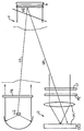
Anhand einer schematischen Darstellung wird mit einer einzigen Figur die Erfindung erläutert.
Das Licht eines Infrarot-Scheinwerfers (Lichtquelle) LQ wird durch einen Polarisator PS gesandt und trifft als polarisiertes Licht LS auf die Vignette V. Bei einer Orientierung der "schnellen Achse" der Viertelwellenlängen-Folie als den Polarisationszustand veränderndes Element PE um 45° relativ zur Schwingungsebene polarisierten Lichts LS des Scheinwerfers wird bei doppeltem Durchgang via Retroreflektor (Reflektor) R das reflektierte Licht LE um 90° gegenüber der Scheinwerferlicht-Polarisation gedreht. Dieses Licht LE wird zu der in unmittelbarer Nachbarschaft zum Infrarot-Scheinwerfer LQ angeordneten Vidokamera VK rückreflektiert und dort in einer Detektor- und Auswerteeinrichtung D detektiert. Durch Anbringen eines Polarisators PE' und eines Interferenzfilters IF vor dem Kameraobjektiv wird faktisch alles Licht bis auf das erwünschte reflektierte Licht LE vom Kamerachip CCD ferngehalten. Das den Polarisationszustand verändernde Element PE ist in Form einer strukturierten Viertelwellen-Folie realisiert, bei der sich drehende Bereiche und nicht drehende Bereiche abwechseln bzw. bei der die Strukturierung darin besteht, daß in bestimmten Regionen die Folie vorhanden ist und in benachbarten nicht. Je nach Orientierung des Polarisatiors PE' vor dem Detektor D relativ zu dem Polarisator PS vor der Lichtquelle LQ sind die drehenden Bereiche hell oder dunkel. Dabei gilt hell für gekreuzte Polarisatoren und dunkel für parallel orientierte Polarisatoren. Die nicht mit Viertelwellen-Folie bestückten Bereiche verhalten sich komplementär. Bei einer Beleuchtung mit nicht polarisiertem oder mit in der Wellenlänge nicht an die Viertelwellen-Folie angepaßtem Licht läßt sich die Infor teil, daß nur bei einer totalen Kopie der Beleuchtungsbedingungen der Vignettenfolie und der geeigneten Detektoren die Vignette ausgelesen werden kann.The invention is explained with the aid of a schematic illustration with a single figure.
The light from an infrared headlamp (light source) LQ is sent through a polarizer PS and hits the vignette V as polarized light LS. With an orientation of the "fast axis" of the quarter-wavelength film as the polarization state changing element PE by 45 ° relative to The plane of vibration of polarized light LS of the headlamp is double-pass via the retroreflector (Reflector) R the reflected light LE rotated by 90 ° with respect to the headlight polarization. This light LE is reflected back to the video camera VK arranged in the immediate vicinity of the infrared headlight LQ and is detected there in a detector and evaluation device D. By attaching a polarizer PE 'and an interference filter IF in front of the camera lens, practically all light apart from the desired reflected light LE is kept away from the camera chip CCD. The element PE which changes the polarization state is realized in the form of a structured quarter-wave film in which rotating areas alternate with non-rotating areas or in which the structuring consists in the fact that the film is present in certain regions and not in neighboring ones. Depending on the orientation of the polarizer PE 'in front of the detector D relative to the polarizer PS in front of the light source LQ, the rotating areas are light or dark. Light applies to crossed polarizers and dark for parallel polarizers. The areas not equipped with quarter-wave film behave complementarily. In the case of illumination with non-polarized light or with light which is not adapted to the quarter-wave film in the wavelength, the information can be provided that the vignette can only be read out with a total copy of the lighting conditions of the vignette film and the suitable detectors.
Claims (17)
dadurch gekennzeichnet, daß die Vignette (V) einen Reflektor (R), der einen Polarisationszustand nicht verändert, aber einen großen Akzeptanzwinkel besitzt, und davor angebracht ein den Polarisationszustand veränderndes Element (PE) aufweist,
daß das den Polarisationszustand verändernde Element (PE) durch Strukturierung die Information in codierter Form erhält,
daß mit zumindest einer Lichtquelle (LQ), die polarisiertes Licht (LS) sendet, die Vignette bestrahlt wird und das reflektierte Licht (LE) von einer Detektor- und Auswerteeinrichtung (D) empfangen und analysiert wird, wobei aufgrund der veränderten Polarisation des von der Detektor- und Auswerteeinrichtung (D) empfangenen reflektierten Lichtes (LE) die Echtheit und/oder Gültigkeit der Vignette erkannt wird.Method for encrypting and checking information in the form of a vignette (V),
characterized in that the vignette (V) has a reflector (R) which does not change a polarization state but has a large acceptance angle and, in front of it, has an element (PE) which changes the polarization state,
that the element (PE) which changes the polarization state receives the information in coded form by structuring,
that with at least one light source (LQ) that sends polarized light (LS), the vignette is irradiated and the reflected light (LE) is received and analyzed by a detector and evaluation device (D), due to the changed polarization of the Detector and evaluation device (D) received reflected light (LE) the authenticity and / or validity of the vignette is recognized.
dadurch gekennzeichnet, daß die Strukturierung des den Polarisationszustand verändernden Elements (PE) durch Stanzen oder Schneiden erfolgt.Method according to claim 1,
characterized in that the structuring of the element (PE) which changes the polarization state takes place by punching or cutting.
dadurch gekennzeichnet, daß die Strukturierung des den Polarisationszustand verändernden Elements (PE) durch örtlich variierende thermische Behandlung erfolgt.Method according to claim 1,
characterized in that the structuring of the element (PE) which changes the polarization state is carried out by locally varying thermal treatment.
dadurch gekennzeichnet, daß die Strukturierung des den Polarisationszustand verändernden Elements (PE) durch Prägen oder Bedrucken erfolgt.Method according to claim 1,
characterized in that the structuring of the element (PE) which changes the polarization state is carried out by embossing or printing.
dadurch gekennzeichnet, daß die Lichtquelle (LQ) und die Detektor- und Auswerteeinrichtung (D) im nahen IR-Bereich betrieben wird.Method according to one of claims 1 to 4,
characterized in that the light source (LQ) and the detector and evaluation device (D) are operated in the near IR range.
dadurch gekennzeichnet, daß das Licht linear polarisiert ausgesendet wird.Method according to one of claims 1 to 5,
characterized in that the light is emitted linearly polarized.
dadurch gekennzeichnet, daß das den Polarisationszustand verändernde Element (PE) der Vignette ein Liquid-Crystal-Display ist, welches im doppelten Licht-Durchgang die Polarisationsebene um 90° dreht und dessen Struktur durch geeignete Pixelierung erzeugt wird.Method according to claim 1,
characterized in that the element (PE) of the vignette which changes the polarization state is a liquid crystal display which rotates the polarization plane by 90 ° in double passage of light and whose structure is generated by suitable pixelation.
dadurch gekennzeichnet, daß ein oder mehrere bildgebende Detektoren mit Polarisationsfiltern von dem abbildenden Objektiv ausgerüstet sind und daß zur Erzeugung von Negativ-/Positiveffekten diese Filter wahlweise um 90° gedreht eingesetzt werden.Method according to one of claims 1 to 7,
characterized in that one or more imaging detectors are equipped with polarization filters from the imaging lens and that these filters are optionally used rotated by 90 ° to produce negative / positive effects.
dadurch gekennzeichnet, daß vor den bildgebenden Detektor oder die bildgebenden Detektoren Bandpaßinterferenzfilter mit geeigneter Durchlaßwellenlänge und Bandbreite geschaltet werden.Method according to one of claims 1 to 7,
characterized in that in front of the imaging detector or the imaging detectors Bandpass interference filters with a suitable transmission wavelength and bandwidth can be switched.
dadurch gekennzeichnet, daß die Lichtquelle von einem IR-Laser gebildet ist und die Bildgebung durch Abtasten erfolgt.Method according to one of claims 1 to 9,
characterized in that the light source is formed by an IR laser and the imaging is carried out by scanning.
dadurch gekennzeichnet, daß der Reflektor (R) der Vignette von einer Retro-Reflektorfolie und das den Polarisationszustand verändernde Element (PE) der Vignette von einem strukturierten Polarisationsfilter gebildet werden.Device for carrying out the method according to one of claims 1 to 10,
characterized in that the reflector (R) of the vignette is formed by a retro reflector film and the element (PE) of the vignette which changes the polarization state is formed by a structured polarization filter.
dadurch gekennzeichnet, daß das Polarisationsfilter von einer Viertelwellenlängen-Folie gebildet wird, deren "schnelle Achse" um 45° gegen die Polarisationsebene des eingestrahlten Lichts gedreht orientiert ist.Device according to claim 11,
characterized in that the polarization filter is formed by a quarter-wavelength film, the "fast axis" of which is oriented rotated by 45 ° with respect to the plane of polarization of the incident light.
dadurch gekennzeichnet, daß das Polarisationsfilter von einer Achtelwellenlängen-Folie gebildet wird und daß das ausgesandte Licht zirkular polarisiert ist.Device according to claim 11,
characterized in that the polarization filter is formed by an eighth wavelength film and that the emitted light is circularly polarized.
dadurch gekennzeichnet, daß das Polarisationsfilter im sichtbaren Lichtbereich eine opake, jedoch im IR-nahen Bereich eine vollständig transparente Folie aufweist.Device according to claim 11,
characterized in that the polarization filter is an opaque in the visible light range, however has a completely transparent film in the IR-near region.
dadurch gekennzeichnet, daß die Vignette an einem KFZ angebracht ist.Device according to claim 11 to 14,
characterized in that the vignette is attached to a motor vehicle.
dadurch gekennzeichnet, daß die Vignette an der Innenseite der Frontscheibe des KFZ's angebracht ist.Device according to claim 15,
characterized in that the vignette is attached to the inside of the front window of the vehicle.
dadurch gekennzeichnet, daß die Lichtquelle (LQ) und die Detektor- und Auswerteeinrichtung (D) in einem Kontrollfahrzeug angeordnet ist.Device according to claim 15 or 16,
characterized in that the light source (LQ) and the detector and evaluation device (D) are arranged in a control vehicle.
Applications Claiming Priority (2)
| Application Number | Priority Date | Filing Date | Title |
|---|---|---|---|
| DE19522928 | 1995-06-23 | ||
| DE19522928A DE19522928C1 (en) | 1995-06-23 | 1995-06-23 | Method and device for encrypting and checking information in the form of a vignette |
Publications (3)
| Publication Number | Publication Date |
|---|---|
| EP0751480A2 true EP0751480A2 (en) | 1997-01-02 |
| EP0751480A3 EP0751480A3 (en) | 2000-04-05 |
| EP0751480B1 EP0751480B1 (en) | 2004-02-11 |
Family
ID=7765138
Family Applications (1)
| Application Number | Title | Priority Date | Filing Date |
|---|---|---|---|
| EP96109348A Expired - Lifetime EP0751480B1 (en) | 1995-06-23 | 1996-06-11 | Method and device for encoding and verifying information in the form of a label |
Country Status (3)
| Country | Link |
|---|---|
| EP (1) | EP0751480B1 (en) |
| AT (1) | ATE259523T1 (en) |
| DE (1) | DE19522928C1 (en) |
Cited By (3)
| Publication number | Priority date | Publication date | Assignee | Title |
|---|---|---|---|---|
| WO1998037514A1 (en) * | 1997-02-24 | 1998-08-27 | The Secretary Of State For Defence | Signature mark recognition systems |
| WO2002023794A2 (en) * | 2000-09-14 | 2002-03-21 | Forskningscenter Risoe | Polarisation encryption/decryption module |
| DE19859126B4 (en) * | 1998-07-24 | 2012-06-28 | Baumer Innotec Ag | Layered arrangement for the retroreflection of light |
Families Citing this family (1)
| Publication number | Priority date | Publication date | Assignee | Title |
|---|---|---|---|---|
| DE10225375B4 (en) * | 2002-06-06 | 2004-06-09 | Codixx Ag | Optical security system |
Citations (10)
| Publication number | Priority date | Publication date | Assignee | Title |
|---|---|---|---|---|
| US4257669A (en) * | 1979-04-16 | 1981-03-24 | Institutul De Cergetari S Proiectari Technologice In Transporturi | Optical-electronic system for the identification of a retro-reflective label |
| WO1990014640A1 (en) * | 1989-05-23 | 1990-11-29 | Australian Electro Optics Pty Ltd | Image processed optical toll gate voucher |
| EP0413948A1 (en) * | 1989-08-21 | 1991-02-27 | Siemens Aktiengesellschaft | System for optical data transmission, preferably for the automatic payment of road taxes |
| EP0449164A2 (en) * | 1990-03-26 | 1991-10-02 | Matsushita Electric Industrial Co., Ltd. | Method for forming a computer generated hologram |
| EP0552564A1 (en) * | 1991-12-26 | 1993-07-28 | Nhk Spring Co.Ltd. | Authenticity identifying structure for an article |
| US5284364A (en) * | 1992-06-10 | 1994-02-08 | Anvik Corporation | Increased-security identification card system |
| DE4230621A1 (en) * | 1992-09-12 | 1994-03-17 | Betr Forsch Inst Angew Forsch | Identifying marking on incandescent workpiece - using scanning laser, narrow bandpass filter and CCD camera |
| DE4317822A1 (en) * | 1993-05-28 | 1994-12-01 | Sel Alcatel Ag | Method and arrangement for unambiguous allocation of measurement results in road traffic |
| US5422473A (en) * | 1990-06-29 | 1995-06-06 | Matsushita Electric Industrial Co., Ltd. | Vehicle security system and automatic roadway toll charging system |
| US5440109A (en) * | 1993-03-31 | 1995-08-08 | Siemens Aktiengesellschaft | Automatic toll ticketing system |
Family Cites Families (1)
| Publication number | Priority date | Publication date | Assignee | Title |
|---|---|---|---|---|
| DE2756632A1 (en) * | 1977-12-19 | 1979-06-28 | Licentia Gmbh | DEVICE FOR FALSE-PROOF IDENTIFICATION OF OBJECTS |
-
1995
- 1995-06-23 DE DE19522928A patent/DE19522928C1/en not_active Expired - Fee Related
-
1996
- 1996-06-11 AT AT96109348T patent/ATE259523T1/en not_active IP Right Cessation
- 1996-06-11 EP EP96109348A patent/EP0751480B1/en not_active Expired - Lifetime
Patent Citations (10)
| Publication number | Priority date | Publication date | Assignee | Title |
|---|---|---|---|---|
| US4257669A (en) * | 1979-04-16 | 1981-03-24 | Institutul De Cergetari S Proiectari Technologice In Transporturi | Optical-electronic system for the identification of a retro-reflective label |
| WO1990014640A1 (en) * | 1989-05-23 | 1990-11-29 | Australian Electro Optics Pty Ltd | Image processed optical toll gate voucher |
| EP0413948A1 (en) * | 1989-08-21 | 1991-02-27 | Siemens Aktiengesellschaft | System for optical data transmission, preferably for the automatic payment of road taxes |
| EP0449164A2 (en) * | 1990-03-26 | 1991-10-02 | Matsushita Electric Industrial Co., Ltd. | Method for forming a computer generated hologram |
| US5422473A (en) * | 1990-06-29 | 1995-06-06 | Matsushita Electric Industrial Co., Ltd. | Vehicle security system and automatic roadway toll charging system |
| EP0552564A1 (en) * | 1991-12-26 | 1993-07-28 | Nhk Spring Co.Ltd. | Authenticity identifying structure for an article |
| US5284364A (en) * | 1992-06-10 | 1994-02-08 | Anvik Corporation | Increased-security identification card system |
| DE4230621A1 (en) * | 1992-09-12 | 1994-03-17 | Betr Forsch Inst Angew Forsch | Identifying marking on incandescent workpiece - using scanning laser, narrow bandpass filter and CCD camera |
| US5440109A (en) * | 1993-03-31 | 1995-08-08 | Siemens Aktiengesellschaft | Automatic toll ticketing system |
| DE4317822A1 (en) * | 1993-05-28 | 1994-12-01 | Sel Alcatel Ag | Method and arrangement for unambiguous allocation of measurement results in road traffic |
Cited By (8)
| Publication number | Priority date | Publication date | Assignee | Title |
|---|---|---|---|---|
| WO1998037514A1 (en) * | 1997-02-24 | 1998-08-27 | The Secretary Of State For Defence | Signature mark recognition systems |
| GB2336927A (en) * | 1997-02-24 | 1999-11-03 | Secr Defence | Signature mark recognition systems |
| GB2336927B (en) * | 1997-02-24 | 2000-05-24 | Secr Defence | Signature mark recognition systems |
| AU724227B2 (en) * | 1997-02-24 | 2000-09-14 | Qinetiq Limited | Signature recognition systems |
| US6522399B1 (en) * | 1997-02-24 | 2003-02-18 | Qinetiq Limited | Signature mark recognition systems |
| DE19859126B4 (en) * | 1998-07-24 | 2012-06-28 | Baumer Innotec Ag | Layered arrangement for the retroreflection of light |
| WO2002023794A2 (en) * | 2000-09-14 | 2002-03-21 | Forskningscenter Risoe | Polarisation encryption/decryption module |
| WO2002023794A3 (en) * | 2000-09-14 | 2007-11-08 | Forskningsct Risoe | Polarisation encryption/decryption module |
Also Published As
| Publication number | Publication date |
|---|---|
| ATE259523T1 (en) | 2004-02-15 |
| EP0751480A3 (en) | 2000-04-05 |
| DE19522928C1 (en) | 1996-12-19 |
| EP0751480B1 (en) | 2004-02-11 |
Similar Documents
| Publication | Publication Date | Title |
|---|---|---|
| EP0366858B1 (en) | Bar code field and bar code reader | |
| EP1040039B1 (en) | Adaptive absolute steering angle sensor | |
| DE19510257A1 (en) | Symbol reading system with reduced mirror type reflection | |
| EP0040839A2 (en) | Identification system for motor vehicles, method and apparatus for realizing such a system, and method and apparatus for reproducing coded information contained in such a system | |
| EP2039527A2 (en) | Diffractive security system with individualised code | |
| EP1983473A1 (en) | Data carrier with codes | |
| EP2240914A1 (en) | Method and device for identifying and authenticating objects | |
| DE102009014437B4 (en) | Object Recognition System and Method | |
| DE102007015934A1 (en) | Document with a security feature, reader and method for reading a security feature | |
| WO2004011273A2 (en) | Method and device for checking authenticity of a security element | |
| EP4212955A1 (en) | Device for a color-based detection of image contents, computing device, and motor vehicle comprising such a device | |
| EP1049064B1 (en) | Traffic monitoring device with polarisation filters | |
| EP2053868B1 (en) | Spatial opto-electronic sensor with test unit and test method | |
| DE102005063331A1 (en) | Light reflecting triplet, for light barrier corner reflectors, has three mirror surfaces with light entries part covered with diffraction pattern carrying covers | |
| DE60213767T2 (en) | OPTICAL IDENTIFICATION AND MARKING SYSTEM | |
| DE19522928C1 (en) | Method and device for encrypting and checking information in the form of a vignette | |
| DE10228013B4 (en) | Partial transmission reflector, use of the partial transmission reflector and optical sensor system | |
| EP0772102A2 (en) | Method for producing counterfeit-proof holograms with authenticity marks, and reading apparatus for checking authenticity | |
| DE102017102556A1 (en) | A method for verifying a security document and a security document, a device and a security element | |
| EP3700756B1 (en) | Reflective security element | |
| CH698365B1 (en) | Apparatus and method for detecting the presence or absence of a component. | |
| DE2756632A1 (en) | DEVICE FOR FALSE-PROOF IDENTIFICATION OF OBJECTS | |
| DE10137817B4 (en) | Device and method for detecting optical markings | |
| EP3086082B1 (en) | Inspection with polarisation filters | |
| EP3841524B1 (en) | Inspection method and inspection device for inspecting security markings |
Legal Events
| Date | Code | Title | Description |
|---|---|---|---|
| PUAI | Public reference made under article 153(3) epc to a published international application that has entered the european phase |
Free format text: ORIGINAL CODE: 0009012 |
|
| AK | Designated contracting states |
Kind code of ref document: A2 Designated state(s): AT BE CH FR GB IT LI LU NL |
|
| PUAL | Search report despatched |
Free format text: ORIGINAL CODE: 0009013 |
|
| AK | Designated contracting states |
Kind code of ref document: A3 Designated state(s): AT BE CH FR GB IT LI LU NL |
|
| RIC1 | Information provided on ipc code assigned before grant |
Free format text: 7G 06K 19/14 A, 7G 06K 19/06 B |
|
| 17P | Request for examination filed |
Effective date: 20001004 |
|
| 17Q | First examination report despatched |
Effective date: 20010223 |
|
| GRAH | Despatch of communication of intention to grant a patent |
Free format text: ORIGINAL CODE: EPIDOS IGRA |
|
| GRAH | Despatch of communication of intention to grant a patent |
Free format text: ORIGINAL CODE: EPIDOS IGRA |
|
| GRAA | (expected) grant |
Free format text: ORIGINAL CODE: 0009210 |
|
| AK | Designated contracting states |
Kind code of ref document: B1 Designated state(s): AT BE CH FR GB IT LI LU NL |
|
| REG | Reference to a national code |
Ref country code: GB Ref legal event code: FG4D Free format text: NOT ENGLISH |
|
| REG | Reference to a national code |
Ref country code: CH Ref legal event code: EP |
|
| REG | Reference to a national code |
Ref country code: CH Ref legal event code: NV Representative=s name: SIEMENS SCHWEIZ AG |
|
| GBT | Gb: translation of ep patent filed (gb section 77(6)(a)/1977) |
Effective date: 20040517 |
|
| ET | Fr: translation filed | ||
| PLBE | No opposition filed within time limit |
Free format text: ORIGINAL CODE: 0009261 |
|
| STAA | Information on the status of an ep patent application or granted ep patent |
Free format text: STATUS: NO OPPOSITION FILED WITHIN TIME LIMIT |
|
| 26N | No opposition filed |
Effective date: 20041112 |
|
| PGFP | Annual fee paid to national office [announced via postgrant information from national office to epo] |
Ref country code: LU Payment date: 20060615 Year of fee payment: 11 |
|
| PGFP | Annual fee paid to national office [announced via postgrant information from national office to epo] |
Ref country code: FR Payment date: 20060623 Year of fee payment: 11 |
|
| PGFP | Annual fee paid to national office [announced via postgrant information from national office to epo] |
Ref country code: IT Payment date: 20060630 Year of fee payment: 11 |
|
| PGFP | Annual fee paid to national office [announced via postgrant information from national office to epo] |
Ref country code: NL Payment date: 20070605 Year of fee payment: 12 |
|
| PGFP | Annual fee paid to national office [announced via postgrant information from national office to epo] |
Ref country code: BE Payment date: 20070615 Year of fee payment: 12 |
|
| PGFP | Annual fee paid to national office [announced via postgrant information from national office to epo] |
Ref country code: GB Payment date: 20070607 Year of fee payment: 12 Ref country code: CH Payment date: 20070906 Year of fee payment: 12 |
|
| REG | Reference to a national code |
Ref country code: FR Ref legal event code: ST Effective date: 20080229 |
|
| PGFP | Annual fee paid to national office [announced via postgrant information from national office to epo] |
Ref country code: AT Payment date: 20080516 Year of fee payment: 13 |
|
| PG25 | Lapsed in a contracting state [announced via postgrant information from national office to epo] |
Ref country code: FR Free format text: LAPSE BECAUSE OF NON-PAYMENT OF DUE FEES Effective date: 20070702 |
|
| BERE | Be: lapsed |
Owner name: SIEMENS A.G. Effective date: 20080630 |
|
| REG | Reference to a national code |
Ref country code: CH Ref legal event code: PL |
|
| GBPC | Gb: european patent ceased through non-payment of renewal fee |
Effective date: 20080611 |
|
| NLV4 | Nl: lapsed or anulled due to non-payment of the annual fee |
Effective date: 20090101 |
|
| PG25 | Lapsed in a contracting state [announced via postgrant information from national office to epo] |
Ref country code: BE Free format text: LAPSE BECAUSE OF NON-PAYMENT OF DUE FEES Effective date: 20080630 |
|
| PG25 | Lapsed in a contracting state [announced via postgrant information from national office to epo] |
Ref country code: NL Free format text: LAPSE BECAUSE OF NON-PAYMENT OF DUE FEES Effective date: 20090101 |
|
| PG25 | Lapsed in a contracting state [announced via postgrant information from national office to epo] |
Ref country code: LI Free format text: LAPSE BECAUSE OF NON-PAYMENT OF DUE FEES Effective date: 20080630 Ref country code: GB Free format text: LAPSE BECAUSE OF NON-PAYMENT OF DUE FEES Effective date: 20080611 Ref country code: CH Free format text: LAPSE BECAUSE OF NON-PAYMENT OF DUE FEES Effective date: 20080630 |
|
| PG25 | Lapsed in a contracting state [announced via postgrant information from national office to epo] |
Ref country code: LU Free format text: LAPSE BECAUSE OF NON-PAYMENT OF DUE FEES Effective date: 20070611 |
|
| PG25 | Lapsed in a contracting state [announced via postgrant information from national office to epo] |
Ref country code: IT Free format text: LAPSE BECAUSE OF NON-PAYMENT OF DUE FEES Effective date: 20070611 |
|
| PG25 | Lapsed in a contracting state [announced via postgrant information from national office to epo] |
Ref country code: AT Free format text: LAPSE BECAUSE OF NON-PAYMENT OF DUE FEES Effective date: 20090611 |