EP0747795B1 - A system for generically describing and scheduling operation of a modular printing machine - Google Patents
A system for generically describing and scheduling operation of a modular printing machine Download PDFInfo
- Publication number
- EP0747795B1 EP0747795B1 EP96304272A EP96304272A EP0747795B1 EP 0747795 B1 EP0747795 B1 EP 0747795B1 EP 96304272 A EP96304272 A EP 96304272A EP 96304272 A EP96304272 A EP 96304272A EP 0747795 B1 EP0747795 B1 EP 0747795B1
- Authority
- EP
- European Patent Office
- Prior art keywords
- machine
- data
- module
- description data
- modules
- Prior art date
- Legal status (The legal status is an assumption and is not a legal conclusion. Google has not performed a legal analysis and makes no representation as to the accuracy of the status listed.)
- Expired - Lifetime
Links
Images


Classifications
-
- G—PHYSICS
- G05—CONTROLLING; REGULATING
- G05B—CONTROL OR REGULATING SYSTEMS IN GENERAL; FUNCTIONAL ELEMENTS OF SUCH SYSTEMS; MONITORING OR TESTING ARRANGEMENTS FOR SUCH SYSTEMS OR ELEMENTS
- G05B19/00—Programme-control systems
- G05B19/02—Programme-control systems electric
- G05B19/04—Programme control other than numerical control, i.e. in sequence controllers or logic controllers
- G05B19/042—Programme control other than numerical control, i.e. in sequence controllers or logic controllers using digital processors
- G05B19/0426—Programming the control sequence
-
- G—PHYSICS
- G05—CONTROLLING; REGULATING
- G05B—CONTROL OR REGULATING SYSTEMS IN GENERAL; FUNCTIONAL ELEMENTS OF SUCH SYSTEMS; MONITORING OR TESTING ARRANGEMENTS FOR SUCH SYSTEMS OR ELEMENTS
- G05B2219/00—Program-control systems
- G05B2219/20—Pc systems
- G05B2219/25—Pc structure of the system
- G05B2219/25093—During start, integration into machine, send module functionality to scheduler
-
- G—PHYSICS
- G05—CONTROLLING; REGULATING
- G05B—CONTROL OR REGULATING SYSTEMS IN GENERAL; FUNCTIONAL ELEMENTS OF SUCH SYSTEMS; MONITORING OR TESTING ARRANGEMENTS FOR SUCH SYSTEMS OR ELEMENTS
- G05B2219/00—Program-control systems
- G05B2219/20—Pc systems
- G05B2219/25—Pc structure of the system
- G05B2219/25296—Identification module, type connected I-O, device
-
- G—PHYSICS
- G05—CONTROLLING; REGULATING
- G05B—CONTROL OR REGULATING SYSTEMS IN GENERAL; FUNCTIONAL ELEMENTS OF SUCH SYSTEMS; MONITORING OR TESTING ARRANGEMENTS FOR SUCH SYSTEMS OR ELEMENTS
- G05B2219/00—Program-control systems
- G05B2219/20—Pc systems
- G05B2219/26—Pc applications
- G05B2219/2646—Printing
Definitions
- the invention pertains generally to the art of printing machines and more particularly to photo-duplication machines such as copiers.
- the invention is particularly applicable to the automated scheduling of printing jobs pursuant to the capabilities associated with modular components forming a printing machine and will be described with particular reference thereto. However, it will be appreciated that the invention has broader application, such as in providing for an automated assessment of machine capabilities in view of modular components, as well as job specific utilization in an efficient manner in view of the same.
- Present day machinery such as photocopiers
- Such fabrication allows for mass production of each of the subassemblies of a machine while simultaneously allowing for customization to consumer's needs.
- a consumer is provided with a means by which he or she may alter or upgrade capabilities of an existing, base unit.
- US-A-4,924,320 describes a modular-type image forming system including a laser printer main unit and a plurality of optional units, such as both-side processing unit, a large-quantity paper feeding unit and a mail box unit, each of which is operatively coupled to said main unit through a commonly usable optical fiber cable through a commonly usable connector.
- Each unit has its own CPU and serial communications between the CPUs of different units may be carried out through the optical cables.
- the CPU of the main unit may determine the identity of each of the optional units connected thereto through such communications.
- the main unit also includes an interface circuit through which the main unit is operatively coupled to each of the optional units.
- the interface circuit includes a port selector which establishes a connection pattern between the main and optional units in accordance with the identity information of each of the optional units connected.
- US-A-5,124,809 describes an image forming system including a processor, a print engine and optional units.
- a serial signal line couples the print engine and the optional units.
- the processor has a command sending function of sending the print engine a command which asks the print engine whether or not the print engine can communicate with each of the optional units.
- the print engine has a function of managing a variety of information including data relating to status of the optional units, and a function of determining, in response to the command, as to whether each of the optional units is in a communication active state where it can communicate with the print engine on the basis of the managed information and a function of sending the processor a response which indicates information on whether each of the optional units is in the communication active state.
- EP 735 430 A2 describes a method of scheduling a job in an imaging system including detecting criteria of the job, determining applicable constraints based upon one or more of the criteria, inputs entered into the imaging system and/or operating the imaging system to output the job such that the constraints are satisfied, thereby maximizing output.
- Each job includes a plurality of images to be processed by the imaging system, which includes at least one imaging device.
- One object of the present invention is to provide a new and improved system and method for automatically ascertaining machine capability and utilizing the same to overcome the above-referred to problems, and others, that provide enhanced usability and configurability both prior to and after the machine leaves the factory.
- the subject system provides for acquisition of module data which represents functional characteristics of each of one or more machine modules.
- Description data associated with each such module represents a structure or function of that particular module.
- the system functions to acquire setup data which represents a mechanical or electrical interrelation between the one or more machine modules.
- An input/output unit received acquired description data and setup data into a scheduler.
- a comparison means is disposed in the scheduler and serves to analyze description data and setup data to determine a set of machine functions practicable by a machine form from the one or more machine modules.
- a system for automatically recognizing a presence of one or more subassemblies and communicating their various functional descriptions to a centralized processor unit for assessment and analysis.
- the system provides for an efficient, automated scheduling of a plurality of print jobs of various or varying characteristics.
- An advantage of the present invention is the provision of a printing machine that may be easily and automatically configured to various or varying subassemblies.
- Another advantage of the present invention is the provision of a printing machine that may be easily configured to maximum potential by an end-user.
- Yet another advantage of the present invention is a provision of a printing machine that maximizes printing throughput by efficiently scheduling and utilizing modular subassemblies in accordance with userspecified print jobs.
- FIGURE 1 illustrates an embodiment of the subject invention having a modular print engine A which includes a plurality of modules or subassemblies B and a dataprocessor unit for configuration and scheduling C.
- Representative print modules in B have been enclosed in dotted lines in FIGURE 1.
- print engine includes any reprographic machine, such as printers, copiers, facsimile machines, and the like.
- each of the modules B are ascertained and correlated in the data processor unit C.
- Such correlated and analyzed data is further analyzed in view of user input defining a desired printer operation, or series of operations. This is, in turn, used to optimize, schedule, and control operation of the printing machine to most efficiently accomplish the series of printing tasks.
- the subject system is described by way of example with a copier machine. It will be appreciated that generic description, resource assessment and scheduling may be practicable on any modular, material handling system.
- the modules B are illustrated as including a plurality of paper storage bins.
- these include bins 10, 12, and 14.
- the plurality of bins may be representative of different paper sizes or secondary or reserved storage capability.
- a sheet feeder mechanism is illustrated schematically at 16.
- a sheet feeder such as that illustrated at 16 will function to obtain sheet stock from one or more of the bins.
- the feeder 16 will feed sheet stock to a conveyor 18 (note: not incorporated into dotted lines).
- the conveyor will, in turn, feed sheet stock to a print mechanism 20, the particular construction of which will be well within the understanding of one of ordinary skill in the art.
- an inverter mechanism 30 that may selectively invert or flip sheet stock that progresses along the conveyor 18.
- a feedbackunit 32 is provided for returning sheet stock to the printer mechanism 20 for duplex printing thereof.
- the conveyor 18 provides a path to a stapling mechanism 34 for selective stapling of printed documents.
- the final, illustrated component in the group of modules B illustrates a plurality of output bins represented by bins 38 and 40.
- modules may be purely mechanical, some may consist of a mixture of mechanical and computational devices, and some may consist only of computational devices.
- a module may consist of a processor, data storage and instruction storage, and a set of functions which are able to accept image data from user input, to process the image data, and to send it to another module for printing. Depending on the speed of these functions, such a module is scheduled and controlled like all other modules B. The invention is intended for all such modules.
- data processor unit C included therein is a data input/output (“I/O") unit 40 which is in data communication with a central processor unit (“CPU”)/storage scheduling unit 42, the details of which will be described further below.
- I/O data input/output
- CPU central processor unit
- storage scheduling unit 42 the details of which will be described further below.
- a data path is provided between the data I/O unit 40 and each of the modules B. It will be appreciated that such data processor unit may be located in one of the modules B, or may be implemented on a separated device connected to the modules.
- each module B includes therein a description associated with various functions and capabilities thereof. The particulars of such a generic description will be detailed below.
- the data path between each of the illustrated modules and the data I/O unit allows for acquisition to the data processor unit C of all such description.
- any module B will communicate its associated description to the data I/O unit upon connection to the modular print engine A. This ability allows for "plug-and-play" capability of the subject system.
- Data interconnections between the data I/O unit 40 of the data processor C and the various modules B also allow for controller activation thereof.
- the data processor unit C has ascertained from the available modules the complete set of capabilities of the modular print engine A.
- This information, coupled with user input 44 to the data I/O unit 40 allows for efficient scheduling of available, modular resources to accomplish a series of printing jobs by use of the available components.
- FIGURE 2 the basic format for generic print engine description and scheduling will be described.
- past attempts for automated print engine scheduling software were based on an analysis of a complete engine configuration. The results of this analysis are required for writing of dedicated software specific to a particular configuration.
- the subject system provides for separation of scheduling software into two parts. In a first part, a scheduler architecture is provided with generic algorithms. In a second part, machine-specific information is also provided in a format detailed below.
- a scheduler which serves to identify, schedule, and initiate machine operations for producing a document.
- such operations may include feeding of sheets, moving of sheets, preparation of images, transferring of images to sheets, etc.
- a document to be printed typically arrives incrementally (e.g., sheet-bysheet).
- Scheduling and schedule execution (printing) usually happen concurrently.
- machinespecific information used by a scheduler is advantageously structured such that the scheduler is able to identify which operations will produce the required sheet.
- the system must be aware of constraints which must be observed when scheduling operations.
- the system is provided with a means by which it may send appropriate commands to the modules to allow them to accomplish their available functions.
- FIGURE 2 the particular system for preparing the machine-specific information is depicted.
- the system commences by using declarative descriptions (models) of printing engine modules in block 100.
- a model advantageously contains description of a module's structure and potential behavior of its components.
- possible components include feed trays, transport belts, transfer components, inverters, gates, etc.
- Potential behaviors may be, by way of example, either bypassing an inverter or using it to invert a sheet.
- the step of modeling is typically performed by an engineer using a modeling language, the details of a preferred embodiment of which will be provided below.
- a module has already been modeled by its components.
- an automatic derivation of potential behaviors of an entire module is then fabricated from information obtained from the component models. This derivation may be performed, by way of example, by simulation or partial evaluation, and by envisionment.
- Simulation is commonly understood as the execution of models to mirror the execution of the real system.
- Partial evaluation is commonly understood as the partial execution of programs, leaving certain parts of the programs unexecuted and to be evaluated at a later time.
- Envisionment is commonly understood as the exploration of all potential behaviors of a system by, for example, repeatedly and in various ways exercising simulation or partial evaluation of its models.
- the resulting module behavior is comprised of an output produced by a particular behavior, inputs from which the output is produced, individual operations required to produce it (its "itinerary"), as well as various constraints on resources and timings to be observed when performing the operations.
- its "itinerary" individual operations required to produce it
- some or all of this information may advantageously be precompiled. By way of example, this may be compiled to finite-state machines.
- print engine modules B (FIGURE 1) are plugged together to form a new configuration, different module behaviors are collected and automatically composed via the data processor unit C to generate potential behaviors of a complete print engine A.
- composition is also suitably enabled to occur dynamically, i.e., each time a behavior is to be selected by the scheduler, it composes module behaviors on-the-fly.
- a composition may be done only once (after modules are first plugged together), or each time they are needed.
- the latter option has an advantage of accounting for dynamic module changes.
- the system may complete the FIGURE 2 sequence each time a machine behavior is selected. It may be prohibitive to do so due to the time-consuming computations. However, this may be a more efficient approach in specific circumstances.
- the afore-noted, overall behavior is advantageously modeled in a format similar to that associated with the individual module behavior noted above.
- the system provides an output description (for behavior identification), resource and timing constraints (for sequencing), and data comprising an itinerary (for subsequent control of machine operations).
- a portion of machine behavior information is advantageously compiled for efficient use in a matching scheduler algorithm at which point the system progresses to block 106.
- a compilation of potential interactions of timing and resource constraints may be made to a finite-state machine.
- a full set of compiled behaviors has been obtained.
- an output description of machine behaviors is used by a generic scheduler to identify behaviors that will produce an output document given the original constraints (either in original or compiled form). These are used to find a correct timing for each particular behaviors' operation and itineraries which are used to initiate necessary operations of the modules B.
- FIGURE 3 a particular system for modeling component behavior will be described.
- the particular system of the preferred embodiment is for a description of print engine component behavior for print engine analysis, simulation, and scheduling.
- the basic, generic description method is equally applicable to various other modular systems.
- print engine components such that print engines fabricated therefrom may be described by composing component descriptions. Further, various applications may be performed automatically on resulting print engine description. This enables one to automatically use such information for analysis, simulation, scheduling, and related print engine applications.
- descriptions associated with an inverter 150 analogous to the inverter 30 of FIGURE 1, are provided with model 150'. Components of a modeled structure and behavior are determined by both physics of the component itself, as well as an application context in which a model is used.
- a structure model of a component is defined as consisting of its physical interface, software interface and internal resources.
- a physical interface is an input port 152 along which work units (sheets) enter and a port 154 from which said work units exit.
- Associated software interface functions primarily for control commands and parameters.
- Internal resources are defined as objects needed to perform a particular behavior, and where multiple uses of the object by repeated execution of the behavior is restricted.
- a resource is defined as the position of an associated gate 156.
- Another example of a resource is a space 158 between opposing output rollers 160 of the inverter 150, particularly illustrated at 150'.
- the space 158 is defined as a resource.
- Which objects to model as resources is at the discretion of the modeler and will be known by one skilled in the art.
- at least one place within a component for example, at entry or exit port of a component
- moving objects use up space or otherwise require exclusive use of a component part is defined as a resource.
- a behavior model of a component is utilized to describe capabilities of the particular component in terms of how the component may work on work units moving through the component. Further, the behavior dictates what constraints must be observed when performing the associated behavior.
- a component capability is defined as consisting of a description of work units and a transformation of work units, timed events like the input and output of a work unit, of resource allocations for this transformation, and of constraints on the timing of such events and resource allocations.
- Work units are advantageously described in terms of their attributes.
- Restrictions and transformations of work units are advantageously described in terms of constraints on their attributes.
- FIGURE 3 some additional model descriptions are provided. These include a description associated with a particular work unit, such as a sheet illustrated at 164.
- a control situation such as to whether or not to by-pass the inverter 150 or utilize it for inversion is illustrated at 166.
- a timing parameter such as a specification of path length and roller speed is provided at 168.
- associated timing constraints are suitably obtained using a formula based on path length and roller speed, e.g., time out may be defined as time in plus path length, divided by roller speed.
- Certain values are also suitably parameters of the model, e.g., the path length of a given inverter is fixed, while roller speed may vary and may therefore be set by the environment with respect to a model that is used.
- a roller speed parameter is illustrated at 170.
- This model declares two parameters (length and speed), one entry port (in), one exit port (out), three resources (inR, outR and gateR, of types Signal respectively State), and six variables (of types Sheet and Interval). Then the model defines two capabilities (bypass and invert). For capability bypass, it is defined that a sheet s enters at time t_in and exits at time t_out, that allocations in all three resources are made at the respective intervals t_in, t_out and t_gate, and that various timing constraints reflecting the traveling time from entry to exit hold between the intervals. Capability invert is defined similarly, except that the sheet changes its orientation by 180° (rotated around the y axis), and that the traveling time is longer (proportional to the sheet's size). Thus, it will be appreciated that a complete and functional description of any component may be similarly provided.
- the disclosed modeling system enables automatic behavioral composition of component capabilities for generic and incremental analysis, simulation, and scheduling of print engines. This description format allows automatic structural composition of component models to models describing connected components (for example, print engine modules).
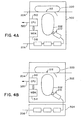
- FIGURES 4A-4B these figures evidence various modules which are suitably implemented in either software or hardware in connection with the subject invention.
- an example which includes a duplex or feedback mechanism 200, an photoreceptor belt 202, a work unit or paper path 204, and an image path 206.
- an image path typically consists of image processing components which are implemented in software or a combination of electronic hardware and software.
- a video image from the image path 206 is suitably layed down onto the photoreceptor belt 202 at a junction 210 and then transferred to a sheet from paper path 204 at a junction 212.
- a module 300 which incorporates image processing directly into the same module provided with the work unit handling capability.
- FIGURE 4B provides separate modules 302 and 304 for an engine module and an image processing module, respectively. It will be appreciated that the examples of FIGURES 4A and 4B are by way of example only. Various other combinations and subcombinations of various work unit handling capability, as well as image handling capabilities, may be implemented in connection with the subject invention.
- the memory 312 includes a non-volatile memory storage portion which is adapted to stored description data representative of the module.
- the system also provides a port 320 adapted for communicating such data to an associated scheduler.
- data may include data representative of at least one of identification, scheduling, and initiation of available operations in the associated scheduler in data communication with the respective module.
- image processing module 304 of FIGURE 4B it will be appreciated that, in the preferred embodiment, similar CPU capability, memory capability, and description data output capability is provided although such has been eliminated from the figure for ease in illustration.
- the fabrication engine 400 includes modules, three of which are evidenced at 402, 404, and 406, respectively.
- the modules include memory suitably comprised of RAM regions 407, 408, and 409, respectively, in addition to non-volatile memory regions 410, 412, and 414, respectively.
- the non-volatile memory is suitably comprised of read only memory (“ROM”), erasable programmable read only memory (“EPROM”), electrically erasable programmable read only memory (“EEPROM”), or the like.
- the non-volatile memory regions 410, 412, and 414 are advantageous for storing capability information, the particulars of which were described in detail above.
- the respective RAM regions allow for scratch pad memory, as well as storage of software to drive an associated CPU.
- CPUs 415, 416, and 417 are provided in modules 402, 404, and 406, respectively.
- FIGURE 5 Also evidenced by FIGURE 5 is a data port 420 which interconnects modules 402 and 404 for communication of work units therebetween. Similarly, a port 422 is provided between modules 404 and 406 for communication of work units therebetween. Finally, each of the modules 402, 404, and 406 are noted to be in data communication with an associated scheduler as evidenced by machine capabilities unit 430.
Description
- The invention pertains generally to the art of printing machines and more particularly to photo-duplication machines such as copiers.
- The invention is particularly applicable to the automated scheduling of printing jobs pursuant to the capabilities associated with modular components forming a printing machine and will be described with particular reference thereto. However, it will be appreciated that the invention has broader application, such as in providing for an automated assessment of machine capabilities in view of modular components, as well as job specific utilization in an efficient manner in view of the same.
- Present day machinery, such as photocopiers, is often fabricated from pre-fabricated components. Such fabrication allows for mass production of each of the subassemblies of a machine while simultaneously allowing for customization to consumer's needs. Further, a consumer is provided with a means by which he or she may alter or upgrade capabilities of an existing, base unit.
- Earlier systems for distributed printing and distributed job scheduling may be found in US-A-5,287,194 and 5,363,175 commonly owned by the assignee hereof.
- Further, US-A-4,924,320 describes a modular-type image forming system including a laser printer main unit and a plurality of optional units, such as both-side processing unit, a large-quantity paper feeding unit and a mail box unit, each of which is operatively coupled to said main unit through a commonly usable optical fiber cable through a commonly usable connector. Each unit has its own CPU and serial communications between the CPUs of different units may be carried out through the optical cables. The CPU of the main unit may determine the identity of each of the optional units connected thereto through such communications. The main unit also includes an interface circuit through which the main unit is operatively coupled to each of the optional units. The interface circuit includes a port selector which establishes a connection pattern between the main and optional units in accordance with the identity information of each of the optional units connected.
- US-A-5,124,809 describes an image forming system including a processor, a print engine and optional units. A serial signal line couples the print engine and the optional units. The processor has a command sending function of sending the print engine a command which asks the print engine whether or not the print engine can communicate with each of the optional units. The print engine has a function of managing a variety of information including data relating to status of the optional units, and a function of determining, in response to the command, as to whether each of the optional units is in a communication active state where it can communicate with the print engine on the basis of the managed information and a function of sending the processor a response which indicates information on whether each of the optional units is in the communication active state.
- EP 735 430 A2 describes a method of scheduling a job in an imaging system including detecting criteria of the job, determining applicable constraints based upon one or more of the criteria, inputs entered into the imaging system and/or operating the imaging system to output the job such that the constraints are satisfied, thereby maximizing output. Each job includes a plurality of images to be processed by the imaging system, which includes at least one imaging device.
- One concern with modular assembly of integrated units is provided with configuring and optimizing use of a completed system. While this is of concern for the manufacturer of an initial unit, it is perhaps an even greater concern to the end user. End users are often technically unsophisticated. However, they are driven by a desire for increased capability of a machine while also a desire to maintain their value of their initial investment. Consumers are also dissuaded from expenses associated with hiring a professional to upgrade or configure existing equipment.
- One object of the present invention is to provide a new and improved system and method for automatically ascertaining machine capability and utilizing the same to overcome the above-referred to problems, and others, that provide enhanced usability and configurability both prior to and after the machine leaves the factory.
- This object is solved by the system as claimed in independent claim 1 and the method as claimed in independent claim 8. Preferred embodiments of the invention are subject-matters of dependent claims.
- In accordance with the present invention, there is provided a system for generically and uniquely describing capabilities of various individual modular machine components.
- The subject system provides for acquisition of module data which represents functional characteristics of each of one or more machine modules. Description data associated with each such module represents a structure or function of that particular module. The system functions to acquire setup data which represents a mechanical or electrical interrelation between the one or more machine modules. An input/output unit received acquired description data and setup data into a scheduler. A comparison means is disposed in the scheduler and serves to analyze description data and setup data to determine a set of machine functions practicable by a machine form from the one or more machine modules.
- In accordance with another aspect of the present invention, a system is provided for automatically recognizing a presence of one or more subassemblies and communicating their various functional descriptions to a centralized processor unit for assessment and analysis.
- In accordance with another aspect of the present invention, the system provides for an efficient, automated scheduling of a plurality of print jobs of various or varying characteristics.
- An advantage of the present invention is the provision of a printing machine that may be easily and automatically configured to various or varying subassemblies.
- Another advantage of the present invention is the provision of a printing machine that may be easily configured to maximum potential by an end-user.
- Yet another advantage of the present invention is a provision of a printing machine that maximizes printing throughput by efficiently scheduling and utilizing modular subassemblies in accordance with userspecified print jobs.
- The present invention will be described further, by way of examples, with reference to the accompanying drawings, in which:
- FIGURE 1 provides a schematic of a representative, modular printing machine incorporating the automated configuration and scheduling of an embodiment of the subject invention;
- FIGURE 2 provides a flow chart detailing the hierarchical ordering of operations to accomplish the configuration and scheduling of the present invention;
- FIGURE 3 provides a diagram of a representative, generic description of a print machine component as used in connection with the subject, automated scheduling and configuration of the subject invention; and
- FIGURE 4A-4B evidence various modules suitable for use in the subject invention; and
- FIGURE 5 is a block diagram of modules interconnected in accordance with the present invention to form a generalized fabrication unit.
-
- Turning now to the drawings wherein the purpose is for illustrating the preferred embodiment of the invention only, and not for the purpose of limiting the same, FIGURE 1 illustrates an embodiment of the subject invention having a modular print engine A which includes a plurality of modules or subassemblies B and a dataprocessor unit for configuration and scheduling C. Representative print modules in B have been enclosed in dotted lines in FIGURE 1. As used herein "print engine" includes any reprographic machine, such as printers, copiers, facsimile machines, and the like.
- As will be detailed below, various capabilities provided with each of the modules B are ascertained and correlated in the data processor unit C. Such correlated and analyzed data is further analyzed in view of user input defining a desired printer operation, or series of operations. This is, in turn, used to optimize, schedule, and control operation of the printing machine to most efficiently accomplish the series of printing tasks. The subject system is described by way of example with a copier machine. It will be appreciated that generic description, resource assessment and scheduling may be practicable on any modular, material handling system.
- With the particular example of FIGURE 1, the modules B are illustrated as including a plurality of paper storage bins. In the illustration, these include
bins - The
feeder 16 will feed sheet stock to a conveyor 18 (note: not incorporated into dotted lines). The conveyor will, in turn, feed sheet stock to aprint mechanism 20, the particular construction of which will be well within the understanding of one of ordinary skill in the art. Also illustrated in the figure is aninverter mechanism 30 that may selectively invert or flip sheet stock that progresses along theconveyor 18. Afeedbackunit 32 is provided for returning sheet stock to theprinter mechanism 20 for duplex printing thereof. - In the illustration, the
conveyor 18 provides a path to astapling mechanism 34 for selective stapling of printed documents. The final, illustrated component in the group of modules B illustrates a plurality of output bins represented bybins - It will be appreciated that some modules may be purely mechanical, some may consist of a mixture of mechanical and computational devices, and some may consist only of computational devices. By way of example regarding the latter, a module may consist of a processor, data storage and instruction storage, and a set of functions which are able to accept image data from user input, to process the image data, and to send it to another module for printing. Depending on the speed of these functions, such a module is scheduled and controlled like all other modules B. The invention is intended for all such modules. Several example modules will be described in connection with FIGURE 4, below.
- Turning to the data processor unit C, included therein is a data input/output ("I/O")
unit 40 which is in data communication with a central processor unit ("CPU")/storage scheduling unit 42, the details of which will be described further below. A data path is provided between the data I/O unit 40 and each of the modules B. It will be appreciated that such data processor unit may be located in one of the modules B, or may be implemented on a separated device connected to the modules. - In the preferred embodiment, each module B includes therein a description associated with various functions and capabilities thereof. The particulars of such a generic description will be detailed below. The data path between each of the illustrated modules and the data I/O unit allows for acquisition to the data processor unit C of all such description. In the preferred embodiment, any module B will communicate its associated description to the data I/O unit upon connection to the modular print engine A. This ability allows for "plug-and-play" capability of the subject system.
- Data interconnections between the data I/
O unit 40 of the data processor C and the various modules B also allow for controller activation thereof. Thus, the data processor unit C has ascertained from the available modules the complete set of capabilities of the modular print engine A. This information, coupled withuser input 44 to the data I/O unit 40 allows for efficient scheduling of available, modular resources to accomplish a series of printing jobs by use of the available components. - Turning next to FIGURE 2, the basic format for generic print engine description and scheduling will be described. As alluded to earlier, past attempts for automated print engine scheduling software were based on an analysis of a complete engine configuration. The results of this analysis are required for writing of dedicated software specific to a particular configuration. Conversely, the subject system provides for separation of scheduling software into two parts. In a first part, a scheduler architecture is provided with generic algorithms. In a second part, machine-specific information is also provided in a format detailed below.
- Given a document to be printed on a given print engine, a scheduler is provided which serves to identify, schedule, and initiate machine operations for producing a document. In the illustration of FIGURE 1, such operations may include feeding of sheets, moving of sheets, preparation of images, transferring of images to sheets, etc. It will be appreciated that a document to be printed typically arrives incrementally (e.g., sheet-bysheet). Scheduling and schedule execution (printing) usually happen concurrently. As a consequence, machinespecific information used by a scheduler is advantageously structured such that the scheduler is able to identify which operations will produce the required sheet. Further, the system must be aware of constraints which must be observed when scheduling operations. Additionally, the system is provided with a means by which it may send appropriate commands to the modules to allow them to accomplish their available functions.
- In the diagram of FIGURE 2, the particular system for preparing the machine-specific information is depicted. The system commences by using declarative descriptions (models) of printing engine modules in
block 100. Such a model advantageously contains description of a module's structure and potential behavior of its components. As noted in the example of FIGURE 1, possible components include feed trays, transport belts, transfer components, inverters, gates, etc. Potential behaviors may be, by way of example, either bypassing an inverter or using it to invert a sheet. The step of modeling is typically performed by an engineer using a modeling language, the details of a preferred embodiment of which will be provided below. - At
block 102, a module has already been modeled by its components. Next, an automatic derivation of potential behaviors of an entire module is then fabricated from information obtained from the component models. This derivation may be performed, by way of example, by simulation or partial evaluation, and by envisionment. Simulation is commonly understood as the execution of models to mirror the execution of the real system. Partial evaluation is commonly understood as the partial execution of programs, leaving certain parts of the programs unexecuted and to be evaluated at a later time. Envisionment is commonly understood as the exploration of all potential behaviors of a system by, for example, repeatedly and in various ways exercising simulation or partial evaluation of its models. The resulting module behavior is comprised of an output produced by a particular behavior, inputs from which the output is produced, individual operations required to produce it (its "itinerary"), as well as various constraints on resources and timings to be observed when performing the operations. Some or all of this information may advantageously be precompiled. By way of example, this may be compiled to finite-state machines. - When print engine modules B (FIGURE 1) are plugged together to form a new configuration, different module behaviors are collected and automatically composed via the data processor unit C to generate potential behaviors of a complete print engine A.
- The afore-noted composition is also suitably enabled to occur dynamically, i.e., each time a behavior is to be selected by the scheduler, it composes module behaviors on-the-fly. Thus, a composition may be done only once (after modules are first plugged together), or each time they are needed. The latter option has an advantage of accounting for dynamic module changes. Thus, the system may complete the FIGURE 2 sequence each time a machine behavior is selected. It may be prohibitive to do so due to the time-consuming computations. However, this may be a more efficient approach in specific circumstances.
- In
block 104, the afore-noted, overall behavior is advantageously modeled in a format similar to that associated with the individual module behavior noted above. Per distinct overall behavior, the system provides an output description (for behavior identification), resource and timing constraints (for sequencing), and data comprising an itinerary (for subsequent control of machine operations). - Next, a portion of machine behavior information is advantageously compiled for efficient use in a matching scheduler algorithm at which point the system progresses to block 106. By way of example, a compilation of potential interactions of timing and resource constraints may be made to a finite-state machine. At
block 108, a full set of compiled behaviors has been obtained. - Lastly, at
block 110, an output description of machine behaviors is used by a generic scheduler to identify behaviors that will produce an output document given the original constraints (either in original or compiled form). These are used to find a correct timing for each particular behaviors' operation and itineraries which are used to initiate necessary operations of the modules B. - While the afore-going description is provided by way of preferred embodiment, it will be appreciated that not all of the steps are required to provide a usable system. For example, only a portion of all components need be modeled and compilation of all constraints need not be accomplished.
- With the system described above, modular ("plug-and-play") scheduling of print engine modules is facilitated. The system also allows for reuse of scheduling software for a wide range of configurations. It also provides for automating all steps but that of obtaining the initial description of the discrete modules forming the machine and for development of the generic scheduling algorithms.
- Turning now to FIGURE 3, a particular system for modeling component behavior will be described. The particular system of the preferred embodiment is for a description of print engine component behavior for print engine analysis, simulation, and scheduling. As noted above, the basic, generic description method is equally applicable to various other modular systems.
- In the subject description method, structure and behavior of components is described in terms of capabilities (potential operations) for which constraints on work units, timings, and resources are stated. This modeling system enables structural and behavioral composition of components for analysis and simulation of component interactions in print engines. The system is particularly applicable for scheduling operation of modular print engines.
- With the subject scheme, one may describe print engine components such that print engines fabricated therefrom may be described by composing component descriptions. Further, various applications may be performed automatically on resulting print engine description. This enables one to automatically use such information for analysis, simulation, scheduling, and related print engine applications. In the illustrated example of FIGURE 3, descriptions associated with an
inverter 150, analogous to theinverter 30 of FIGURE 1, are provided with model 150'. Components of a modeled structure and behavior are determined by both physics of the component itself, as well as an application context in which a model is used. - In the system, a structure model of a component is defined as consisting of its physical interface, software interface and internal resources. For example, a physical interface is an
input port 152 along which work units (sheets) enter and aport 154 from which said work units exit. Associated software interface functions primarily for control commands and parameters. Internal resources are defined as objects needed to perform a particular behavior, and where multiple uses of the object by repeated execution of the behavior is restricted. By way of example in FIGURE 3, a resource is defined as the position of an associated gate 156. Another example of a resource is aspace 158 between opposing output rollers 160 of theinverter 150, particularly illustrated at 150'. Here, as with most points of the paper path, there is sufficient space for only one sheet at any single point in time. Thus, thespace 158 is defined as a resource. Which objects to model as resources is at the discretion of the modeler and will be known by one skilled in the art. Typically, at least one place within a component (for example, at entry or exit port of a component) where moving objects use up space or otherwise require exclusive use of a component part is defined as a resource. - A behavior model of a component is utilized to describe capabilities of the particular component in terms of how the component may work on work units moving through the component. Further, the behavior dictates what constraints must be observed when performing the associated behavior.
- A component capability is defined as consisting of a description of work units and a transformation of work units, timed events like the input and output of a work unit, of resource allocations for this transformation, and of constraints on the timing of such events and resource allocations. Work units are advantageously described in terms of their attributes. Restrictions and transformations of work units are advantageously described in terms of constraints on their attributes.
- In FIGURE 3, some additional model descriptions are provided. These include a description associated with a particular work unit, such as a sheet illustrated at 164. A control situation, such as to whether or not to by-pass the
inverter 150 or utilize it for inversion is illustrated at 166. A timing parameter, such as a specification of path length and roller speed is provided at 168. By way of example, associated timing constraints are suitably obtained using a formula based on path length and roller speed, e.g., time out may be defined as time in plus path length, divided by roller speed. Certain values are also suitably parameters of the model, e.g., the path length of a given inverter is fixed, while roller speed may vary and may therefore be set by the environment with respect to a model that is used. A roller speed parameter is illustrated at 170. - By way of particular example, the following listing provides a suitable model of an inverter as depicted in connection with FIGURE 3:

- This model declares two parameters (length and speed), one entry port (in), one exit port (out), three resources (inR, outR and gateR, of types Signal respectively State), and six variables (of types Sheet and Interval). Then the model defines two capabilities (bypass and invert). For capability bypass, it is defined that a sheet s enters at time t_in and exits at time t_out, that allocations in all three resources are made at the respective intervals t_in, t_out and t_gate, and that various timing constraints reflecting the traveling time from entry to exit hold between the intervals. Capability invert is defined similarly, except that the sheet changes its orientation by 180° (rotated around the y axis), and that the traveling time is longer (proportional to the sheet's size). Thus, it will be appreciated that a complete and functional description of any component may be similarly provided.
- With the disclosed modeling system, a component structure is described without relying on any reference to descriptions of or interactions with other components. Such component behavior is described on one work unit without other units. Further, the disclosed modeling system enables automatic behavioral composition of component capabilities for generic and incremental analysis, simulation, and scheduling of print engines. This description format allows automatic structural composition of component models to models describing connected components (for example, print engine modules).
- Conversely, earlier approaches had their capabilities and constraints expressed in terms of both specific interactions between components and interactions between sequences of sheets or images. This renders them more difficult to define, renders them non-reusable, and further renders them non-compositional. The system modeling format allows for the automatic configuration, optimization, and scheduling described above.
- Turning now to FIGURES 4A-4B, these figures evidence various modules which are suitably implemented in either software or hardware in connection with the subject invention. In each of the modules of FIGURE 4A-4B, provided in common is an example which includes a duplex or
feedback mechanism 200, anphotoreceptor belt 202, a work unit orpaper path 204, and animage path 206. It is noted that an image path typically consists of image processing components which are implemented in software or a combination of electronic hardware and software. In each example, a video image from theimage path 206 is suitably layed down onto thephotoreceptor belt 202 at ajunction 210 and then transferred to a sheet frompaper path 204 at ajunction 212. - Turning particularly to the example of FIGURE 4A, provided is a
module 300 which incorporates image processing directly into the same module provided with the work unit handling capability. - The example of FIGURE 4B provides
separate modules - In each of the modules in the examples of FIGURES 4A and 4B, also evidenced is a
CPU 310 and an associated memory disposed in an address space thereof. In the preferred embodiment, thememory 312 includes a non-volatile memory storage portion which is adapted to stored description data representative of the module. The system also provides aport 320 adapted for communicating such data to an associated scheduler. As noted above, such data may include data representative of at least one of identification, scheduling, and initiation of available operations in the associated scheduler in data communication with the respective module. In theimage processing module 304 of FIGURE 4B, it will be appreciated that, in the preferred embodiment, similar CPU capability, memory capability, and description data output capability is provided although such has been eliminated from the figure for ease in illustration. - Turning now to FIGURE 5, a
generalized fabrication engine 400 is provided. Thefabrication engine 400 includes modules, three of which are evidenced at 402, 404, and 406, respectively. The modules include memory suitably comprised ofRAM regions non-volatile memory regions - The
non-volatile memory regions CPUs modules - Also evidenced by FIGURE 5 is a
data port 420 which interconnectsmodules port 422 is provided betweenmodules modules machine capabilities unit 430.
Claims (13)
- A system for generating an automated machine operation schedule, comprising:module data acquisition means (310) adapted for acquiring description data representative of functional characteristics of a plurality of machine modules (B; 300, 302, 304; 402, 404, 406), the description data associated with each module (B; 300, 302, 304; 402, 404, 406) including data representative of a machine module structure, function or capabilities, wherein each machine module (B; 300, 302, 304; 402, 404, 406) is comprised of at least one of an electro-mechanical and software component adapted for performing operations on at least one work unit, the acquired description data of each of the plurality of machine modules (B; 300, 302, 304; 402, 404, 406) being independent of the structure, function or capabilities of any other machine module (B; 300, 302, 304; 402, 404, 406);means (420, 422) for acquiring setup data representative of at least one of mechanical and electrical interrelationships between the plurality of machine modules (B; 300, 302, 304; 402, 404, 406);an input/output unit (420, 422) for receiving acquired description data and setup data' into a generic scheduler (C: 42), the generic scheduler (C: 42) configured to operate independent of the description data representative of the structure, function, or capabilities of the plurality of machine modules (B; 300, 302, 304; 402, 404, 406), the generic scheduler (C: 42) including a data storage, a processor, and an instruction storage; andcomparison means, disposed in the generic scheduler (C: 42), for analyzing the description data and the setup data to determine a set of machine functions practicable by a machine (A) comprised of the machine modules (B; 300, 302, 304; 402, 404, 406).
- The system of claim 1, further comprising at least one machine module (B; 300, 302, 304; 402, 404, 406) including:a memory (312) storing description data; anda data port (320, 420) adapted for communicating description data associated therewith to the module data acquisition means (310).
- The system of claim 1 or 2, further comprising:means for receiving input representative of a user-specified machine output;means for communicating the operator input to the comparison means; andthe generic scheduler (C: 42) further including control means for generating a control signal adapted for controlling each machine module (B; 300, 302, 304; 402, 404, 406) in accordance with determined machine functions to accomplish the user-specified machine output.
- The system of one of claims 1 to 3, further comprising:
means for performing analysis of the description data by implementation of at least one of partial evaluation, simulation, abduction and envisionment on the description data. - The system of one of claims 1 to 4, further comprising:means for determining a presence of each machine module (B; 300, 302, 304; 402, 404, 406) in data communication with the module data acquisition means (310); andmeans for automatically communicating the description data from each machine module (B; 300, 302, 304; 402, 404, 406) identified by the determining means, whereby setup data is generated.
- The system of one of claims 1 to 5 wherein the comparison means further includes:
means for dynamically re-analyzing the description data each time a machine module (B; 300, 302, 304; 402, 404, 406) is placed in or removed from data communication with the module data acquisition means (310). - The system of one of claims 1 to 6 wherein the generic scheduler (C: 42) is a predictive scheduler.
- A method of generating an automated operation schedule, comprising:acquiring description data representative of functional characteristics of a plurality of machine modules (B; 300, 302, 304; 402, 404, 406), the description data associated with each machine module (B; 300, 302, 304; 402, 404, 406) including data representative of a module structure,function, or capabilities thereof, the acquired description data of a machine module (B; 300, 302, 304; 402, 404, 406) being independent of the structure, function or capabilities of any other machine module (B; 300, 302, 304; 402, 404, 406);acquiring setup data representative of at least one of mechanical and electrical interrelationships between the plurality of machine modules (B; 300, 302, 304; 402, 404, 406);receiving the acquired description data and setup data into a generic scheduler (C: 42), the generic scheduler (C: 42) including a data storage, a processor, and an instruction storage, the generic scheduler (C: 42) configured to operate independent of the description data representative of the structure, function, or capabilities of the plurality of modules (B; 300, 302, 304; 402, 404, 406); andanalyzing, via the generic scheduler (C: 42), the description data and the setup data to determine a set of functions practicable by a machine (A) comprised of the machine modules (B; 300, 302, 304; 402, 404, 406).
- The method of claim 8, further comprising:
communicating the description data stored within each of at least one machine module (B; 300, 302, 304; 402, 404, 406) to the generic scheduler (C: 42). - The method of claim 8 or 9, further comprising:receiving operator input representative of a user-specified machine output into the generic scheduler (C: 42); andgenerating control signaling adapted for controlling each machine module (B; 300, 302, 304; 402, 404, 406) in accordance with determined machine functions to accomplish the user-specified machine output.
- The method of one of claims 8 to 10 wherein the step of analyzing includes:
performing analysis of the description data by implementation of at least one of partial evaluation, simulation, abduction and envisionment on the description data. - The method of one of claims 8 to 11, further comprising:determining each machine module (B; 300, 302, 304; 402, 404, 406) capable of supplying the description data; andautomatically communicating the description data from each determined machine module (B; 300, 302, 304; 402, 404, 406) to the generic scheduler (C: 42).
- The method of one of claims 8 to 12 wherein the step of analyzing includes:
dynamically re-analyzing the description data each time a machine module (B; 300, 302, 304; 402, 404, 406) is placed in or removed from data communication with the generic scheduler (C: 42).
Applications Claiming Priority (2)
| Application Number | Priority Date | Filing Date | Title |
|---|---|---|---|
| US476510 | 1995-06-07 | ||
| US08/476,510 US5696893A (en) | 1995-06-07 | 1995-06-07 | System for generically describing and scheduling operation of modular printing machine |
Publications (3)
| Publication Number | Publication Date |
|---|---|
| EP0747795A2 EP0747795A2 (en) | 1996-12-11 |
| EP0747795A3 EP0747795A3 (en) | 1998-10-21 |
| EP0747795B1 true EP0747795B1 (en) | 2001-10-17 |
Family
ID=23892141
Family Applications (1)
| Application Number | Title | Priority Date | Filing Date |
|---|---|---|---|
| EP96304272A Expired - Lifetime EP0747795B1 (en) | 1995-06-07 | 1996-06-07 | A system for generically describing and scheduling operation of a modular printing machine |
Country Status (4)
| Country | Link |
|---|---|
| US (1) | US5696893A (en) |
| EP (1) | EP0747795B1 (en) |
| JP (1) | JPH091897A (en) |
| DE (1) | DE69615926T2 (en) |
Cited By (4)
| Publication number | Priority date | Publication date | Assignee | Title |
|---|---|---|---|---|
| US6640151B1 (en) | 1999-12-22 | 2003-10-28 | Applied Materials, Inc. | Multi-tool control system, method and medium |
| US6708074B1 (en) | 2000-08-11 | 2004-03-16 | Applied Materials, Inc. | Generic interface builder |
| US7725208B2 (en) | 2001-06-19 | 2010-05-25 | Applied Materials, Inc. | Dynamic metrology schemes and sampling schemes for advanced process control in semiconductor processing |
| US8694145B2 (en) | 2001-06-19 | 2014-04-08 | Applied Materials, Inc. | Feedback control of a chemical mechanical polishing device providing manipulation of removal rate profiles |
Families Citing this family (47)
| Publication number | Priority date | Publication date | Assignee | Title |
|---|---|---|---|---|
| US5784077A (en) * | 1995-04-12 | 1998-07-21 | Eastman Kodak Company | Digital printing using plural cooperative modular printing devices |
| US6199201B1 (en) * | 1998-08-03 | 2001-03-06 | Xerox Corporation | Software constructs that facilitate partial evaluation of source code |
| US6430569B1 (en) * | 1998-08-14 | 2002-08-06 | Sun Microsystems, Inc. | Methods and apparatus for type safe, lazy, user-defined class loading |
| US6601114B1 (en) | 1999-05-27 | 2003-07-29 | Sun Microsystems, Inc. | Fully lazy linking with module-by-module verification |
| US6766521B1 (en) | 1999-05-27 | 2004-07-20 | Sun Microsystems, Inc. | Dataflow algorithm for symbolic computation of lowest upper bound type |
| US6618769B1 (en) | 1999-05-27 | 2003-09-09 | Sun Microsystems, Inc. | Module-by-module verification |
| US6763397B1 (en) | 1999-05-27 | 2004-07-13 | Sun Microsystems, Inc. | Fully lazy linking |
| US6618855B1 (en) | 1999-05-27 | 2003-09-09 | Sun Microsystems, Inc. | Caching untrusted modules for module-by-module verification |
| US6850336B1 (en) | 1999-08-10 | 2005-02-01 | Xerox Corporation | Print engine scheduling method and apparatus |
| US6856411B1 (en) * | 1999-08-10 | 2005-02-15 | Xerox Corporation | Policy driven print engine |
| US6625508B1 (en) | 1999-08-10 | 2003-09-23 | Xerox Corporation | Dynamically varying policy driven print engine |
| US6836339B1 (en) | 1999-08-10 | 2004-12-28 | Xerox Corporation | Print engine scheduler with configurable traverser |
| US6618167B1 (en) | 1999-12-17 | 2003-09-09 | Xerox Corporation | Apparatus and method for document scheduling in order to improve the productivity of a networked printer |
| US9785140B2 (en) | 2000-02-01 | 2017-10-10 | Peer Intellectual Property Inc. | Multi-protocol multi-client equipment server |
| US8028049B1 (en) * | 2000-02-01 | 2011-09-27 | Peer Intellectual Property Inc. | Apparatus and method for web-based tool management |
| US7403984B2 (en) | 2000-02-01 | 2008-07-22 | Asyst Technologies, Inc. | Automated tool management in a multi-protocol environment |
| US7873428B2 (en) | 2005-04-15 | 2011-01-18 | PEER Intellectual Property, Inc. | Automated job management |
| DE10015423A1 (en) * | 2000-03-28 | 2001-10-11 | Siemens Ag | Modular automated process system |
| KR100849104B1 (en) * | 2000-09-06 | 2008-07-30 | 어플라이드 머티어리얼즈 인코포레이티드 | Dispatching component for associating manufacturing facility service requestors with service providers |
| US7188142B2 (en) | 2000-11-30 | 2007-03-06 | Applied Materials, Inc. | Dynamic subject information generation in message services of distributed object systems in a semiconductor assembly line facility |
| US7756963B2 (en) | 2001-07-05 | 2010-07-13 | PEER Intellectual Property, Inc. | Automated tool management in a multi-protocol environment |
| US20030199112A1 (en) | 2002-03-22 | 2003-10-23 | Applied Materials, Inc. | Copper wiring module control |
| EP1557074A4 (en) * | 2002-10-22 | 2010-01-13 | Sullivan Jason | Robust customizable computer processing system |
| US7233405B2 (en) | 2002-10-30 | 2007-06-19 | Palo Alto Research Center, Incorporated | Planning and scheduling reconfigurable systems with regular and diagnostic jobs |
| US8315898B2 (en) * | 2002-10-30 | 2012-11-20 | Palo Alto Research Center, Incorporated | Planning and scheduling reconfigurable systems around off-line resources |
| US7230736B2 (en) * | 2002-10-30 | 2007-06-12 | Palo Alto Research Center, Incorporated | Planning and scheduling reconfigurable systems with alternative capabilities |
| AU2003290932A1 (en) | 2002-11-15 | 2004-06-15 | Applied Materials, Inc. | Method, system and medium for controlling manufacture process having multivariate input parameters |
| DE10254010B4 (en) * | 2002-11-19 | 2009-01-02 | Siemens Ag | Method for automatic configuration of a parameterization surface of machine tools or production machines |
| EP1457847A3 (en) * | 2003-03-10 | 2010-01-13 | Heidelberger Druckmaschinen Aktiengesellschaft | System and method for identifying modules in a printing machine |
| US6895292B2 (en) * | 2003-04-28 | 2005-05-17 | Palo Alto Research Center Inc. | Predictive and preemptive planning and scheduling for different job priorities system and method |
| US7139629B2 (en) * | 2003-04-28 | 2006-11-21 | Palo Alto Research Center Incorporated | Planning and scheduling for failure recovery system and method |
| US6856845B2 (en) * | 2003-04-28 | 2005-02-15 | Palo Alto Research Center Inc. | Monitoring and reporting incremental job status system and method |
| DE102004015240A1 (en) * | 2004-03-29 | 2005-10-27 | Siemens Ag | Modular machine and corresponding method for dynamically configuring the topology of this machine |
| US7043321B2 (en) * | 2004-05-27 | 2006-05-09 | Palo Alto Research Center Incorporated | Exception handling in manufacturing systems combining on-line planning and predetermined rules |
| US7787138B2 (en) | 2005-05-25 | 2010-08-31 | Xerox Corporation | Scheduling system |
| US7493055B2 (en) * | 2006-03-17 | 2009-02-17 | Xerox Corporation | Fault isolation of visible defects with manual module shutdown options |
| US7302199B2 (en) * | 2005-05-25 | 2007-11-27 | Xerox Corporation | Document processing system and methods for reducing stress therein |
| US7742185B2 (en) | 2004-08-23 | 2010-06-22 | Xerox Corporation | Print sequence scheduling for reliability |
| US7619769B2 (en) | 2005-05-25 | 2009-11-17 | Xerox Corporation | Printing system |
| US7667874B2 (en) * | 2005-07-06 | 2010-02-23 | Xerox Corporation | Method and system for improving print quality |
| US7593684B2 (en) * | 2005-08-30 | 2009-09-22 | Xerox Corporation | Systems and methods for medium registration |
| US8477333B2 (en) * | 2006-01-27 | 2013-07-02 | Xerox Corporation | Printing system and bottleneck obviation through print job sequencing |
| DE102008010011A1 (en) * | 2008-02-20 | 2009-10-29 | Dr. Johannes Heidenhain Gmbh | Procedure for commissioning a numerical control |
| US8151267B2 (en) * | 2008-04-08 | 2012-04-03 | Xerox Corporation | Printing system scheduler methods and systems |
| US8237964B2 (en) * | 2009-02-05 | 2012-08-07 | Xerox Corporation | Print job scheduling for processing print jobs based on user set delay criteria |
| JP5327452B2 (en) * | 2009-03-13 | 2013-10-30 | 株式会社リコー | Information processing device |
| CN103197586B (en) * | 2013-04-11 | 2015-04-15 | 南京盘谷电气科技有限公司 | Automatic identification technology of distribution network terminal based on microprocessor |
Family Cites Families (26)
| Publication number | Priority date | Publication date | Assignee | Title |
|---|---|---|---|---|
| US5056014A (en) * | 1985-02-04 | 1991-10-08 | Lockheed Sanders, Inc. | Network simulation system |
| JPS63212948A (en) * | 1987-02-28 | 1988-09-05 | Ricoh Co Ltd | Image forming system |
| JP2989191B2 (en) * | 1988-11-16 | 1999-12-13 | 株式会社リコー | Image forming system |
| US4991176A (en) * | 1989-06-07 | 1991-02-05 | At&T Bell Laboratories | Optimal test generation for finite state machine models |
| US5161115A (en) * | 1989-09-12 | 1992-11-03 | Kabushiki Kaisha Toshiba | System test apparatus for verifying operability |
| US5125098A (en) * | 1989-10-06 | 1992-06-23 | Sanders Associates, Inc. | Finite state-machine employing a content-addressable memory |
| US5038307A (en) * | 1989-10-30 | 1991-08-06 | At&T Bell Laboratories | Measurement of performance of an extended finite state machine |
| US5095342A (en) * | 1990-09-28 | 1992-03-10 | Xerox Corporation | Methods for sheet scheduling in an imaging system having an endless duplex paper path loop |
| US5095369A (en) * | 1990-09-28 | 1992-03-10 | Xerox Corporation | Method and apparatus for improved job stream printing in an electronic printer with various finishing function |
| US5107299A (en) * | 1990-09-28 | 1992-04-21 | Xerox Corporation | Printer job recovery of complete or partially complete jobs in an electronic reprographic printing system |
| US5179410A (en) * | 1990-09-28 | 1993-01-12 | Xerox Corporation | Printer dynamic job recovery in an electronic reprographic printing system |
| US5187587A (en) * | 1990-09-28 | 1993-02-16 | Xerox Corporation | Handling of copy sensitive jobs in an electronic reprographic printing system using unidirectional and bidirectional delivery of copies to plural bins |
| US5301100A (en) * | 1991-04-29 | 1994-04-05 | Wagner Ferdinand H | Method of and apparatus for constructing a control system and control system created thereby |
| US5495339A (en) * | 1991-08-19 | 1996-02-27 | Xerox Corporation | Scheduling multiple disk requests and writing data buffers to disk |
| US5159395A (en) * | 1991-08-29 | 1992-10-27 | Xerox Corporation | Method of scheduling copy sheets in a dual mode duplex printing system |
| US5184185A (en) * | 1991-08-29 | 1993-02-02 | Xerox Corporation | Method for duplex printing scheduling system combining finisher interset skipped pitches with duplex sheet scheduling |
| JP2759011B2 (en) * | 1991-10-28 | 1998-05-28 | 株式会社東芝 | Image forming device |
| US5227643A (en) * | 1991-10-28 | 1993-07-13 | Monarch Marking Systems, Inc. | Barcode identification system |
| US5179637A (en) * | 1991-12-02 | 1993-01-12 | Eastman Kodak Company | Method and apparatus for distributing print jobs among a network of image processors and print engines |
| US5469533A (en) * | 1992-07-10 | 1995-11-21 | Microsoft Corporation | Resource-oriented printer system and method of operation |
| US5287194A (en) * | 1992-11-25 | 1994-02-15 | Xerox Corporation | Distributed printing |
| US5375202A (en) * | 1993-01-04 | 1994-12-20 | Xerox Corporation | Dispatching and scheduling memory operations in an electronic printing system |
| US5363175A (en) * | 1993-03-01 | 1994-11-08 | Xerox Corporation | Distributed job scheduling with modular components |
| US5325528A (en) * | 1993-04-22 | 1994-06-28 | Digital Equipment Corporation | Distributed computation recovery management system and method |
| US5337135A (en) * | 1993-09-30 | 1994-08-09 | Xerox Corporation | Higher productivity trayless duplex printer with variable path velocity |
| US5557367A (en) * | 1995-03-27 | 1996-09-17 | Xerox Corporation | Method and apparatus for optimizing scheduling in imaging devices |
-
1995
- 1995-06-07 US US08/476,510 patent/US5696893A/en not_active Expired - Lifetime
-
1996
- 1996-06-05 JP JP8142994A patent/JPH091897A/en active Pending
- 1996-06-07 DE DE69615926T patent/DE69615926T2/en not_active Expired - Lifetime
- 1996-06-07 EP EP96304272A patent/EP0747795B1/en not_active Expired - Lifetime
Cited By (5)
| Publication number | Priority date | Publication date | Assignee | Title |
|---|---|---|---|---|
| US6640151B1 (en) | 1999-12-22 | 2003-10-28 | Applied Materials, Inc. | Multi-tool control system, method and medium |
| US6708074B1 (en) | 2000-08-11 | 2004-03-16 | Applied Materials, Inc. | Generic interface builder |
| US7725208B2 (en) | 2001-06-19 | 2010-05-25 | Applied Materials, Inc. | Dynamic metrology schemes and sampling schemes for advanced process control in semiconductor processing |
| US7783375B2 (en) | 2001-06-19 | 2010-08-24 | Applied Materials, Inc. | Dynamic metrology schemes and sampling schemes for advanced process control in semiconductor processing |
| US8694145B2 (en) | 2001-06-19 | 2014-04-08 | Applied Materials, Inc. | Feedback control of a chemical mechanical polishing device providing manipulation of removal rate profiles |
Also Published As
| Publication number | Publication date |
|---|---|
| US5696893A (en) | 1997-12-09 |
| JPH091897A (en) | 1997-01-07 |
| DE69615926D1 (en) | 2001-11-22 |
| EP0747795A3 (en) | 1998-10-21 |
| EP0747795A2 (en) | 1996-12-11 |
| DE69615926T2 (en) | 2002-04-04 |
Similar Documents
| Publication | Publication Date | Title |
|---|---|---|
| EP0747795B1 (en) | A system for generically describing and scheduling operation of a modular printing machine | |
| EP0747790B1 (en) | Automatic print engine software configuration system | |
| EP0747793B1 (en) | Modular print engine scheduling method | |
| EP0747794B1 (en) | Modular print engine scheduling system | |
| EP0747791B1 (en) | Method for generating finite-state machines for modular print engine scheduling | |
| EP0747792B1 (en) | Modular print engine assessment method using models | |
| EP0778515B1 (en) | Generic assembly trees for job control and mix and match of modules | |
| US5559606A (en) | Flexible configuration of document output terminals from autonomous machine modules | |
| US5701557A (en) | Machine graphs and capabilities to represent document output terminals composed of arbitrary configurations | |
| CA2446796C (en) | Planning and scheduling reconfigurable systems with alternative capabilities | |
| JP4777608B2 (en) | Reconfigurable system planning and scheduling system and method around offline resources | |
| CA2447067C (en) | Planning and scheduling reconfigurable systems with regular and diagnostic jobs | |
| EP0778514B1 (en) | Production trees for generic representation of document requirements for particular output terminals | |
| US5646740A (en) | Partial or untimed production trees to specify diagnostics operations requiring multiple module cooperation | |
| US5631740A (en) | Transducers with constraints model for print scheduling | |
| US5682247A (en) | Partial or untimed production trees to specify specific output terminal operation | |
| US5617214A (en) | Commitment groups to generalize the scheduling of interdependent document output terminal capabilities | |
| EP0586186A2 (en) | Scheduling page parameter variations for discrete job elements | |
| US5617215A (en) | Assembly trees for canonical representation of documents and blending multiple functions |
Legal Events
| Date | Code | Title | Description |
|---|---|---|---|
| PUAI | Public reference made under article 153(3) epc to a published international application that has entered the european phase |
Free format text: ORIGINAL CODE: 0009012 |
|
| AK | Designated contracting states |
Kind code of ref document: A2 Designated state(s): DE FR GB |
|
| PUAL | Search report despatched |
Free format text: ORIGINAL CODE: 0009013 |
|
| AK | Designated contracting states |
Kind code of ref document: A3 Designated state(s): DE FR GB |
|
| 17P | Request for examination filed |
Effective date: 19990421 |
|
| 17Q | First examination report despatched |
Effective date: 19991229 |
|
| GRAG | Despatch of communication of intention to grant |
Free format text: ORIGINAL CODE: EPIDOS AGRA |
|
| GRAG | Despatch of communication of intention to grant |
Free format text: ORIGINAL CODE: EPIDOS AGRA |
|
| GRAH | Despatch of communication of intention to grant a patent |
Free format text: ORIGINAL CODE: EPIDOS IGRA |
|
| GRAH | Despatch of communication of intention to grant a patent |
Free format text: ORIGINAL CODE: EPIDOS IGRA |
|
| GRAA | (expected) grant |
Free format text: ORIGINAL CODE: 0009210 |
|
| AK | Designated contracting states |
Kind code of ref document: B1 Designated state(s): DE FR GB |
|
| REF | Corresponds to: |
Ref document number: 69615926 Country of ref document: DE Date of ref document: 20011122 |
|
| REG | Reference to a national code |
Ref country code: GB Ref legal event code: IF02 |
|
| ET | Fr: translation filed | ||
| PLBE | No opposition filed within time limit |
Free format text: ORIGINAL CODE: 0009261 |
|
| STAA | Information on the status of an ep patent application or granted ep patent |
Free format text: STATUS: NO OPPOSITION FILED WITHIN TIME LIMIT |
|
| 26N | No opposition filed | ||
| REG | Reference to a national code |
Ref country code: FR Ref legal event code: PLFP Year of fee payment: 20 |
|
| PGFP | Annual fee paid to national office [announced via postgrant information from national office to epo] |
Ref country code: DE Payment date: 20150521 Year of fee payment: 20 Ref country code: GB Payment date: 20150527 Year of fee payment: 20 |
|
| PGFP | Annual fee paid to national office [announced via postgrant information from national office to epo] |
Ref country code: FR Payment date: 20150526 Year of fee payment: 20 |
|
| REG | Reference to a national code |
Ref country code: DE Ref legal event code: R071 Ref document number: 69615926 Country of ref document: DE |
|
| REG | Reference to a national code |
Ref country code: GB Ref legal event code: PE20 Expiry date: 20160606 |
|
| PG25 | Lapsed in a contracting state [announced via postgrant information from national office to epo] |
Ref country code: GB Free format text: LAPSE BECAUSE OF EXPIRATION OF PROTECTION Effective date: 20160606 |