EP0747082A2 - Self-capping needle assembly - Google Patents
Self-capping needle assembly Download PDFInfo
- Publication number
- EP0747082A2 EP0747082A2 EP96304186A EP96304186A EP0747082A2 EP 0747082 A2 EP0747082 A2 EP 0747082A2 EP 96304186 A EP96304186 A EP 96304186A EP 96304186 A EP96304186 A EP 96304186A EP 0747082 A2 EP0747082 A2 EP 0747082A2
- Authority
- EP
- European Patent Office
- Prior art keywords
- assembly
- cap
- needle
- hub
- catheter
- Prior art date
- Legal status (The legal status is an assumption and is not a legal conclusion. Google has not performed a legal analysis and makes no representation as to the accuracy of the status listed.)
- Withdrawn
Links
Images

Classifications
-
- A—HUMAN NECESSITIES
- A61—MEDICAL OR VETERINARY SCIENCE; HYGIENE
- A61M—DEVICES FOR INTRODUCING MEDIA INTO, OR ONTO, THE BODY; DEVICES FOR TRANSDUCING BODY MEDIA OR FOR TAKING MEDIA FROM THE BODY; DEVICES FOR PRODUCING OR ENDING SLEEP OR STUPOR
- A61M25/00—Catheters; Hollow probes
- A61M25/01—Introducing, guiding, advancing, emplacing or holding catheters
- A61M25/06—Body-piercing guide needles or the like
- A61M25/0612—Devices for protecting the needle; Devices to help insertion of the needle, e.g. wings or holders
- A61M25/0631—Devices for protecting the needle; Devices to help insertion of the needle, e.g. wings or holders having means for fully covering the needle after its withdrawal, e.g. needle being withdrawn inside the handle or a cover being advanced over the needle
-
- A—HUMAN NECESSITIES
- A61—MEDICAL OR VETERINARY SCIENCE; HYGIENE
- A61M—DEVICES FOR INTRODUCING MEDIA INTO, OR ONTO, THE BODY; DEVICES FOR TRANSDUCING BODY MEDIA OR FOR TAKING MEDIA FROM THE BODY; DEVICES FOR PRODUCING OR ENDING SLEEP OR STUPOR
- A61M25/00—Catheters; Hollow probes
- A61M25/01—Introducing, guiding, advancing, emplacing or holding catheters
- A61M25/06—Body-piercing guide needles or the like
- A61M25/0612—Devices for protecting the needle; Devices to help insertion of the needle, e.g. wings or holders
- A61M25/0618—Devices for protecting the needle; Devices to help insertion of the needle, e.g. wings or holders having means for protecting only the distal tip of the needle, e.g. a needle guard
-
- A—HUMAN NECESSITIES
- A61—MEDICAL OR VETERINARY SCIENCE; HYGIENE
- A61M—DEVICES FOR INTRODUCING MEDIA INTO, OR ONTO, THE BODY; DEVICES FOR TRANSDUCING BODY MEDIA OR FOR TAKING MEDIA FROM THE BODY; DEVICES FOR PRODUCING OR ENDING SLEEP OR STUPOR
- A61M5/00—Devices for bringing media into the body in a subcutaneous, intra-vascular or intramuscular way; Accessories therefor, e.g. filling or cleaning devices, arm-rests
- A61M5/178—Syringes
- A61M5/31—Details
- A61M5/32—Needles; Details of needles pertaining to their connection with syringe or hub; Accessories for bringing the needle into, or holding the needle on, the body; Devices for protection of needles
- A61M5/3205—Apparatus for removing or disposing of used needles or syringes, e.g. containers; Means for protection against accidental injuries from used needles
- A61M5/321—Means for protection against accidental injuries by used needles
- A61M5/3243—Means for protection against accidental injuries by used needles being axially-extensible, e.g. protective sleeves coaxially slidable on the syringe barrel
- A61M5/3275—Means for protection against accidental injuries by used needles being axially-extensible, e.g. protective sleeves coaxially slidable on the syringe barrel being connected to the needle hub or syringe by radially deflectable members, e.g. longitudinal slats, cords or bands
Definitions
- the present invention provides an improved self-capping disposable needle assembly for use in combination with a skin puncture apparatus. More specifically, the present invention relates to an improved self-capping disposable needle assembly for use with a skin puncture apparatus such as a catheter assembly which contains a pleated sleeve made from any natural or synthetic fiber material. Moreover, the fiber material employed as the pleated sleeve may be braided, non-woven or woven and it, optionally, may be treated with a suitable agent that provides the fiber with a hydrophobic coating. Such a coating will prevent unwanted fluids such as blood from seeping through the fiber material during use.
- skin puncture apparatus is used herein to denote devices that are employed in the medical profession to pierce the skin of a patient. Such devices include IV catheter assemblies, intrascopic devices, hypodermic syringe assemblies, biopsy needles and sutures.
- puncture resistant containers One way of avoiding accidental contamination and/or injury is to advise health care workers to place disposable needles in puncture resistant containers.
- puncture resistant containers represents a viable solution to the aforementioned problem, it is not a practical way since it presupposes that puncture resistant containers are available in all circumstances wherein contamination could occur.
- a needle assembly which includes a hub for connecting the assembly to a fluid conduit.
- the hub includes a passageway extending therethrough to receive a hollow needle in fluid communication therewith.
- the cap has a neutral position along the needle adjacent to the hub for exposing a length of the needle, and an extended position for capping the distal tip of the needle.
- the needle is disposed within a passageway of a catheter assembly whereby removal of the needle from the passageway of the catheter assembly moves the cap to the extended position, capping the distal tip as the cap is unseated from the catheter assembly.
- U.S. Patent No. 5,312,371 to Dombrowski et al. More specifically, this patent relates to a method for making a self-capping needle and catheter assembly which includes placing a needle hub and cap on a pin, with the pin extending through the passageway thereof. Two sheets of organic polymeric material are placed on the hub and the cap. The sleeve containing this organic polymeric material is then permanently stretched to a predetermined length. The cap, hub and organic polymeric sleeve are, according to this patent, placed on a needle and the cap is moved against the hub, folding the sleeve therebetween for reception of the catheter assembly.
- the sleeves are made of an organic polymeric material which are pleated into bellows using elaborate and costly thermal processes.
- the plastic sleeves employed in the Dombrowski et al. patents have low tensile strength and high elongation. Thus, under some circumstances the sleeve may break resulting in possible contamination and/or injury of the person handling the needle.
- the present invention is directed to an improved pleated sleeve material for use in self-capping needle assemblies which are adapted to receive a skin puncture apparatus connected thereto.
- the pleated sleeve materials employed in the present invention include braided, woven or non-woven fibers such as dacron, silk, cotton, polyester, rayon, wool, linen, satin and the like. Mixtures of these fibers are also contemplated herein. Such fibers have higher tensile strengths and lower elongation values than the pleated sleeves that are fabricated from organic polymeric materials. Because of these properties, the fiber sleeves of the instant invention are stronger than those heretofore known. Moreover, the fiber sleeves of the present invention, which include any natural or synthetic fiber, can be pleated or formed into bellows without the need for elaborate and expensive thermal processes such as those employed in the prior art.
- the term skin puncture apparatus is used herein to denote medical devices that are employed in the health industry to pierce the skin of a patient.
- Illustrative examples of such skin puncture apparatuses that may be employed in the instant invention include, but are not limited to, IV catheter assemblies, intrascopic devices, hypodermic syringe assemblies, biopsy needles, sutures and the like. Of these skin puncture apparatuses, catheters are particularly preferred.
- the fiber material is treated with a suitable agent that forms a pleated sleeve which contains a hydrophobic coating thereon.
- a suitable agent that forms a pleated sleeve which contains a hydrophobic coating thereon.
- Such a coating prevents blood and/or fluids that are inside the sleeve from seeping through the fiber material.
- Specific types of agents that may be employed in the instant invention are fluorocarbon-based materials that have a low energy effect when applied to the natural or synthetic fibers.
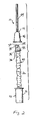
- Figure 1 is a longitudinal cross-sectional view of a needle assembly that may be employed in the present invention.
- Figure 2 is a side view of a catheter being completely removed from the needle assembly.
- the present invention provides an improved pleated sleeve material for use in self-capping disposable needle assemblies that are adapted for use with a skin puncture apparatus.
- a wide variety of needle assemblies and skin puncture apparatuses may be employed in the present invention, reference is made to the accompanying drawings which illustrate one type of needle assembly and catheter assembly that may be employed in the present invention.
- the needle assembly 10 of the instant invention includes a combination of a hypodermic needle assembly 12 and a catheter assembly 14.
- Other skin puncture apparatuses such as intrascopic devices, hypodermic syringe assemblies, biopsy needles and sutures may be used in place of catheter assembly 14.
- the hypodermic needle assembly 12 includes a hub portion 16 having an inner cup shaped surface 18 adapted to be connected to a syringe barrel 20.
- the hub 16 of the hypodermic needle assembly includes a passageway 22 extending therethrough.
- the hub 16 also includes a radially outwardly extending flange 24 which is employed in the present invention to secure hub 16 to syringe barrel 20 with an appropriate type of locking mechanism such as a luer-locking mechanism.
- Needle assembly 10 further includes a hollow metallic needle 26 having a base 28 which is reversibly fitted into passageway 22 of hub 16.
- the hollow needle is in fluid communication with passageway 22 and it includes a distal tip 30 which is a sharp pointed beveled portion adapted for puncturing the skin of a patient.
- a distal tip is well known to those skilled in this art.
- Needle assembly 10 also includes a cap 32 having a neutral position along needle 26 positioned near hub 16 for exposing the length of needle 26 as shown in Figure 1.
- Cap 32 also has an extended position for capping distal tip 30 as shown in Figure 2.
- Cap 32 includes a cap passageway 34 to allow passage of needle 26 therethrough and an inner surface 35 having at least one flange 36 extending therefrom and tapered towards hub 16. The flange 36 forms closed corners 38 defined by inner surface 35.
- flange 36 covers needle tip 30 and prevents the needle tip from re-entering passageway 34.
- the cap 32 contains an outer seating surface not shown in the accompanying drawings for receiving the catheter assembly 14.
- Needle assembly 10 also includes a sleeve 40 for connecting cap 32 to hub 16.
- the sleeve 40 also serves to limit the extent cap 32 can be extended from hub 16.
- Cap 32 may extend from hub 16 to the full length of needle 26 and, when in combination with flange 36, it deflects the needle tip 30 into closed corners 38. The needle tip is thereafter locked under cap 32 when it is relocated to the extended position.
- flange 36 is in combination with sleeve 40, thus providing a sufficient means for locking cap 32 over distal tip 30 of needle 26.
- Sleeve 40 employed in the present invention is in the form of an expandable pleated or bellow-shaped sleeve interconnecting hub 16 and cap 32 for perfecting a seal and closure about the full length of needle 26 when the cap is extended as shown in Figure 2.
- the sleeve is made from any natural or synthetic fiber material. More specifically, the fiber materials that are employed in the present invention as the sleeve material may be braided, woven or non-woven fibers. Specific types of fiber materials that may be employed in the present invention as sleeve 40 include, but are not limited to, silk, cotton, rayon, linen, dacron, wool, satin, nylon, polyester and the like. Mixtures of the fiber materials are also contemplated in the present invention. Of these fibers, polyesters are particularly preferred as the sleeve material.
- sleeve 40 when sleeve 40 is composed of a fiber material it will have a higher tensile strength and lower elongation value compared to plastic materials that are commonly employed in the prior art as the sleeve material. Because of the foregoing properties, the sleeve of the present invention is highly resistant to accidental breakage and it is easier to expand over needle 26.
- Sleeve 40 is made by forming two sheets of fiber material about hub 16 and cap 32, sealing the edges thereof, and fastening it to hub 16 and cap 32.
- the sealing of the edges of the two fiber materials and the fastening to hub 16 and cap 32 are performed using conventional techniques that are well known to those skilled in this particular field.
- the fiber material is coated with an agent which provides sleeve 40 with a hydrophobic coating.
- an agent which provides sleeve 40 with a hydrophobic coating By forming a hydrophobic coating around sleeve 40, fluids inside the sleeve, such as blood, are prevented from seeping through the sleeve material.
- Suitable agents that may be used to provide sleeve 40 with a hydrophobic coating include fluorocarbon-based materials which have a low surface energy effect on the fiber material when applied thereto. Specific examples of such fluorocarbon-based materials include, but are not limited to, fluoromethane, fluoroethane, fluoropropane, fluoroethene, fluoropropene and the like. Mixtures of these fluorocarbon-based materials are also contemplated in the present invention.
- the hydrophobic coating may be provided using conventional coating techniques that are well known to those skilled in the art.
- the hydrophobic coating may be provided to the fiber material by lamination, direct calendaring, direct coating or transfer coating.
- lamination direct calendaring
- direct coating transfer coating
- catheter assembly 14 used in the present invention.
- other skin puncture apparatuses such as intrascopic devices, hypodermic syringe apparatuses, biopsy needles and sutures may be used instead of catheter assembly 14.
- the catheter assembly 14 shown in Figure 2 includes a shaft portion 44 which is disposed about the uncovered length of needle 26 and acts to expose distal tip 30. In this particularly position, distal tip 30 may initiate a puncture through a patient's skin and gain entry to the patient such that shaft portion 44 of the catheter 14 enters the patient.
- the catheter assembly 14 also contains a catheter hub 46 connected to shaft portion 44 and having an inner surface for releasable seating on the cap seating surface 48 whereby removal of needle 26 from shaft 44 moves cap 32 to the extended position, as hub 46 of the catheter assembly is unseated from the seating surface of cap 32.
- Distal tip 30 of needle 26 is concurrently capped as needle 26 is removed from the catheter assembly.
- a person administering the injection such as a nurse or doctor does not have to remove needle assembly 12 from catheter assembly 14, and then separately cap distal tip 30 of needle 26. This greatly reduces the probability of accidental contamination and/or injury. Instead, needle 26 is capped in a single motion. It should be noted that sleeve 40 of the present invention also maintains cap 32 locked against distal tip 30.
- seating surface 48 provides an outer cylindrical or frustoconical surface for cap 32.
- the catheter hub 46 includes an inner complementing surface defining a seat in friction fit over seating surface 48 when cap 32 is in a neutral position. Other reversible methods of seating or connecting the seating surface are also contemplated in the present invention.
- the hub 46 also includes radially outwardly extending annular flange 50 which permits for a luer lock of the catheter.
- catheter assembly 14 is seated over cap 32 and both are disposed adjacent to hub 16. After catherization, the hub portion 16 is moved away from the catheter 14 withdrawing needle 26 from the catheter and extending sleeve 40.
- the hub 16 depending on the particular use may or may not contain a hypodermic syringe assembly 20.
- the present invention provides a more efficient and safer means for catherizing a patient than heretofore known.
- sleeve 40 is made from a braided, woven or non-woven fiber, it has a higher tensile strength and lower elongation value than would a sleeve made of plastic material.
- Such properties result in a needle assembly which is more durable and less likely to break than those disclosed in the prior art.
- the sleeves of the present invention are pleated using conventional processes which are less expensive and not as elaborate as those required for pleating plastic sleeves.
Abstract
Description
- The present invention provides an improved self-capping disposable needle assembly for use in combination with a skin puncture apparatus. More specifically, the present invention relates to an improved self-capping disposable needle assembly for use with a skin puncture apparatus such as a catheter assembly which contains a pleated sleeve made from any natural or synthetic fiber material. Moreover, the fiber material employed as the pleated sleeve may be braided, non-woven or woven and it, optionally, may be treated with a suitable agent that provides the fiber with a hydrophobic coating. Such a coating will prevent unwanted fluids such as blood from seeping through the fiber material during use.
- In today's health industry, there is an ongoing risk of exposure to infectious diseases such as human immunodeficiency virus (HIV) and other AIDS related viruses by health care workers who are continuously utilizing skin puncture apparatuses for injecting patients with medicaments. The term skin puncture apparatus is used herein to denote devices that are employed in the medical profession to pierce the skin of a patient. Such devices include IV catheter assemblies, intrascopic devices, hypodermic syringe assemblies, biopsy needles and sutures.
- Because of this potential risk, disposable needles are considered by many individuals in the health care industry as being potentially infective and are accordingly handled with great care to avoid accidental contamination and/or injury. Moreover, a great deal of effort has gone into developing improved needle assemblies which are safer to handle and which prevent accidents from occurring.
- One way of avoiding accidental contamination and/or injury is to advise health care workers to place disposable needles in puncture resistant containers. Although the use of puncture resistant containers represents a viable solution to the aforementioned problem, it is not a practical way since it presupposes that puncture resistant containers are available in all circumstances wherein contamination could occur.
- In recent years it has become more convenient and safer to provide capping assemblies secured to each needle for immediate capping after use of the needle. One such capping assembly is disclosed in U.S. Patent No. 3,134,380 to Armao. Specifically, this patent discloses a retractable needle guard which extends over the length of the needle assembly prior to use and is retracted as the needle is inserted into a patient. In the typical needle assembly of this kind, a shield which covers a significant portion of the needle shaft is provided at all times. Several drawbacks accordingly are associated with these types of needle assemblies. For example, these types of needle assemblies have less usable needle length when a conventional needle is adapted to the assembly; or they require a significantly longer needle shaft.
Additionally, all the prior art needle assemblies of this type leave the distal tip of the needle exposed or capable of being exposed. Moreover, the tip of the needle is not locked in a completely enclosed guard. Therefore, needle assemblies as described in Armao may not fully protect health care workers from accidental contamination and/or injury. - More recent needle assemblies which overcome the aforementioned problems have been developed and are currently being used in health industries today. Such needle assemblies are described, for example, in U.S. Patent Nos. 4,978,344 and 4,994,041, both to Dombrowski et al. Specifically, these patents to Dombrowski et al. disclose a needle assembly which includes a hub for connecting the assembly to a fluid conduit. The hub includes a passageway extending therethrough to receive a hollow needle in fluid communication therewith. The cap has a neutral position along the needle adjacent to the hub for exposing a length of the needle, and an extended position for capping the distal tip of the needle. The needle is disposed within a passageway of a catheter assembly whereby removal of the needle from the passageway of the catheter assembly moves the cap to the extended position, capping the distal tip as the cap is unseated from the catheter assembly.
- A variation of the needle assemblies disclosed in the foregoing Dombrowski et al. patents is disclosed in U.S. Patent No. 5,312,371 to Dombrowski et al. More specifically, this patent relates to a method for making a self-capping needle and catheter assembly which includes placing a needle hub and cap on a pin, with the pin extending through the passageway thereof. Two sheets of organic polymeric material are placed on the hub and the cap. The sleeve containing this organic polymeric material is then permanently stretched to a predetermined length. The cap, hub and organic polymeric sleeve are, according to this patent, placed on a needle and the cap is moved against the hub, folding the sleeve therebetween for reception of the catheter assembly.
- In all of the foregoing Dombrowski et al. patents, the sleeves are made of an organic polymeric material which are pleated into bellows using elaborate and costly thermal processes. Moreover, in addition to being formed through complicated processing techniques, the plastic sleeves employed in the Dombrowski et al. patents have low tensile strength and high elongation. Thus, under some circumstances the sleeve may break resulting in possible contamination and/or injury of the person handling the needle.
- In light of the prior art and the problems associated with those needle assemblies, research is ongoing to develop new and improved needle assemblies which are extremely safe to use and which overcome the drawbacks mentioned hereinabove.
- The present invention is directed to an improved pleated sleeve material for use in self-capping needle assemblies which are adapted to receive a skin puncture apparatus connected thereto. The pleated sleeve materials employed in the present invention include braided, woven or non-woven fibers such as dacron, silk, cotton, polyester, rayon, wool, linen, satin and the like. Mixtures of these fibers are also contemplated herein. Such fibers have higher tensile strengths and lower elongation values than the pleated sleeves that are fabricated from organic polymeric materials. Because of these properties, the fiber sleeves of the instant invention are stronger than those heretofore known. Moreover, the fiber sleeves of the present invention, which include any natural or synthetic fiber, can be pleated or formed into bellows without the need for elaborate and expensive thermal processes such as those employed in the prior art.
- As stated hereinabove, the term skin puncture apparatus is used herein to denote medical devices that are employed in the health industry to pierce the skin of a patient. Illustrative examples of such skin puncture apparatuses that may be employed in the instant invention include, but are not limited to, IV catheter assemblies, intrascopic devices, hypodermic syringe assemblies, biopsy needles, sutures and the like. Of these skin puncture apparatuses, catheters are particularly preferred.
- In a highly preferred embodiment of the present invention, the fiber material is treated with a suitable agent that forms a pleated sleeve which contains a hydrophobic coating thereon. Such a coating prevents blood and/or fluids that are inside the sleeve from seeping through the fiber material. Specific types of agents that may be employed in the instant invention are fluorocarbon-based materials that have a low energy effect when applied to the natural or synthetic fibers.
- Figure 1 is a longitudinal cross-sectional view of a needle assembly that may be employed in the present invention.
- Figure 2 is a side view of a catheter being completely removed from the needle assembly.
- As stated above, the present invention provides an improved pleated sleeve material for use in self-capping disposable needle assemblies that are adapted for use with a skin puncture apparatus. Although a wide variety of needle assemblies and skin puncture apparatuses may be employed in the present invention, reference is made to the accompanying drawings which illustrate one type of needle assembly and catheter assembly that may be employed in the present invention.
- It should be noted that the basic structure of both the needle assembly and catheter assembly described hereinbelow and as depicted in the accompanying drawings are well known to those skilled in this art. For example, such structures are disclosed in U.S. Patent Nos. 4,790,828, 4,994,041 and 5,312,371 all to Dombrowski et al. It also emphasized that the sleeve materials of the present invention may be used in other needle assemblies and skin puncture apparatuses that are known to those skilled in this art.
- In each of the figures, the needle assembly is indicated as 10. The
needle assembly 10 of the instant invention includes a combination of ahypodermic needle assembly 12 and acatheter assembly 14. Other skin puncture apparatuses such as intrascopic devices, hypodermic syringe assemblies, biopsy needles and sutures may be used in place ofcatheter assembly 14. - Specifically, the
hypodermic needle assembly 12 includes ahub portion 16 having an inner cup shapedsurface 18 adapted to be connected to asyringe barrel 20. Thehub 16 of the hypodermic needle assembly includes apassageway 22 extending therethrough. Thehub 16 also includes a radially outwardly extendingflange 24 which is employed in the present invention to securehub 16 tosyringe barrel 20 with an appropriate type of locking mechanism such as a luer-locking mechanism. -
Needle assembly 10 further includes a hollowmetallic needle 26 having abase 28 which is reversibly fitted intopassageway 22 ofhub 16. The hollow needle is in fluid communication withpassageway 22 and it includes adistal tip 30 which is a sharp pointed beveled portion adapted for puncturing the skin of a patient. Such a distal tip is well known to those skilled in this art. -
Needle assembly 10 also includes acap 32 having a neutral position alongneedle 26 positioned nearhub 16 for exposing the length ofneedle 26 as shown in Figure 1.Cap 32 also has an extended position for cappingdistal tip 30 as shown in Figure 2.Cap 32 includes a cap passageway 34 to allow passage ofneedle 26 therethrough and aninner surface 35 having at least oneflange 36 extending therefrom and tapered towardshub 16. Theflange 36 forms closedcorners 38 defined byinner surface 35. - In the extend position which is shown in Figure 2,
flange 36 coversneedle tip 30 and prevents the needle tip from re-entering passageway 34. Thecap 32 contains an outer seating surface not shown in the accompanying drawings for receiving thecatheter assembly 14. -
Needle assembly 10 also includes asleeve 40 for connectingcap 32 tohub 16. Thesleeve 40 also serves to limit theextent cap 32 can be extended fromhub 16.Cap 32 may extend fromhub 16 to the full length ofneedle 26 and, when in combination withflange 36, it deflects theneedle tip 30 into closedcorners 38. The needle tip is thereafter locked undercap 32 when it is relocated to the extended position. Whensleeve 40 is fully extended,flange 36 is in combination withsleeve 40, thus providing a sufficient means for lockingcap 32 overdistal tip 30 ofneedle 26. -
Sleeve 40 employed in the present invention is in the form of an expandable pleated or bellow-shapedsleeve interconnecting hub 16 andcap 32 for perfecting a seal and closure about the full length ofneedle 26 when the cap is extended as shown in Figure 2. - In accordance with the instant invention, the sleeve is made from any natural or synthetic fiber material. More specifically, the fiber materials that are employed in the present invention as the sleeve material may be braided, woven or non-woven fibers. Specific types of fiber materials that may be employed in the present invention as
sleeve 40 include, but are not limited to, silk, cotton, rayon, linen, dacron, wool, satin, nylon, polyester and the like. Mixtures of the fiber materials are also contemplated in the present invention. Of these fibers, polyesters are particularly preferred as the sleeve material. - As stated above, when
sleeve 40 is composed of a fiber material it will have a higher tensile strength and lower elongation value compared to plastic materials that are commonly employed in the prior art as the sleeve material. Because of the foregoing properties, the sleeve of the present invention is highly resistant to accidental breakage and it is easier to expand overneedle 26. -
Sleeve 40 is made by forming two sheets of fiber material abouthub 16 andcap 32, sealing the edges thereof, and fastening it tohub 16 andcap 32. The sealing of the edges of the two fiber materials and the fastening tohub 16 andcap 32 are performed using conventional techniques that are well known to those skilled in this particular field. - In a highly preferred embodiment of the instant invention, the fiber material is coated with an agent which provides
sleeve 40 with a hydrophobic coating. By forming a hydrophobic coating aroundsleeve 40, fluids inside the sleeve, such as blood, are prevented from seeping through the sleeve material. Suitable agents that may be used to providesleeve 40 with a hydrophobic coating include fluorocarbon-based materials which have a low surface energy effect on the fiber material when applied thereto. Specific examples of such fluorocarbon-based materials include, but are not limited to, fluoromethane, fluoroethane, fluoropropane, fluoroethene, fluoropropene and the like. Mixtures of these fluorocarbon-based materials are also contemplated in the present invention. - The hydrophobic coating may be provided using conventional coating techniques that are well known to those skilled in the art. For example, the hydrophobic coating may be provided to the fiber material by lamination, direct calendaring, direct coating or transfer coating. The foregoing description provides a detailed account of the
needle assembly 10 employed in the present invention. - The following provides a description of the
catheter assembly 14 used in the present invention. As stated above other skin puncture apparatuses such as intrascopic devices, hypodermic syringe apparatuses, biopsy needles and sutures may be used instead ofcatheter assembly 14. - The
catheter assembly 14 shown in Figure 2 includes ashaft portion 44 which is disposed about the uncovered length ofneedle 26 and acts to exposedistal tip 30. In this particularly position,distal tip 30 may initiate a puncture through a patient's skin and gain entry to the patient such thatshaft portion 44 of thecatheter 14 enters the patient. Thecatheter assembly 14 also contains acatheter hub 46 connected toshaft portion 44 and having an inner surface for releasable seating on thecap seating surface 48 whereby removal ofneedle 26 fromshaft 44 moves cap 32 to the extended position, ashub 46 of the catheter assembly is unseated from the seating surface ofcap 32.Distal tip 30 ofneedle 26 is concurrently capped asneedle 26 is removed from the catheter assembly. - By adopting the above structure, a person administering the injection such as a nurse or doctor does not have to remove
needle assembly 12 fromcatheter assembly 14, and then separately capdistal tip 30 ofneedle 26. This greatly reduces the probability of accidental contamination and/or injury. Instead, needle 26 is capped in a single motion. It should be noted thatsleeve 40 of the present invention also maintainscap 32 locked againstdistal tip 30. - In accordance with the present invention, seating
surface 48 provides an outer cylindrical or frustoconical surface forcap 32. Thecatheter hub 46 includes an inner complementing surface defining a seat in friction fit overseating surface 48 whencap 32 is in a neutral position. Other reversible methods of seating or connecting the seating surface are also contemplated in the present invention. Thehub 46 also includes radially outwardly extendingannular flange 50 which permits for a luer lock of the catheter. - In operation,
catheter assembly 14 is seated overcap 32 and both are disposed adjacent tohub 16. After catherization, thehub portion 16 is moved away from thecatheter 14 withdrawingneedle 26 from the catheter and extendingsleeve 40. Thehub 16 depending on the particular use may or may not contain ahypodermic syringe assembly 20. - After
cap 32 is fully extended so thatflange 36 is covered bydistal tip 30 inclosed corners 38, the length ofsleeve 40 acts to limit any further extension ofcap 32, andflange 36 deflectsdistal tip 30 to prevent it from re-enteringcap passageway 22 by moving it intoclosed corners 38 thereby irreversibly cappingneedle 26. As is illustrated in Figure 2, upon further removal ofneedle assembly 10 fromcatheter assembly 14,cap 32 becomes unseated fromcatheter hub 46. When catherization is done in one single motion, the withdrawal of the remainder of the needle assembly from thecatheter assembly 14 extends and coverscap 32 overdistal tip 30 while simultaneously releasing the catheter therefrom. - Thus, the present invention provides a more efficient and safer means for catherizing a patient than heretofore known. Moreover, since
sleeve 40 is made from a braided, woven or non-woven fiber, it has a higher tensile strength and lower elongation value than would a sleeve made of plastic material. Such properties result in a needle assembly which is more durable and less likely to break than those disclosed in the prior art. Furthermore, unlike plastic sleeves which require elaborate and expensive thermal processes for pleating, the sleeves of the present invention are pleated using conventional processes which are less expensive and not as elaborate as those required for pleating plastic sleeves. - While the present invention has been particularly shown and described with respect to preferred embodiments thereof, it will be understood by one skilled in the art that the foregoing and other changes in form and details may be made therein without departing from the spirit and scope of the instant invention.
Claims (11)
- A disposable needle assembly, for use in combination with a skin puncture apparatus, said assembly comprising a needle assembly which contains a pleated sleeve, wherein said pleated sleeve is made from a natural or synthetic fiber material.
- The assembly of claim 1 wherein said needle assembly further comprises:a hub portion for connecting said needle assembly to a fluid conduit, said hub portion including a passageway extending therethrough;a hollow needle portion in fluid communication with said hub passageway, said needle portion having a distal tip relative to said hub portion;a cap including said pleated sleeve for connecting the hub portion to said cap and limiting the extent to which the cap can be extended from the hub portion; andlocking means for locking said cap over said distal tip when said pleated sleeve is fully extended;said cap having a neutral position along said needle portion near said hub portion of said needle assembly for exposing a length of said needle portion, and an extended position for capping said distal tip.
- The assembly of claim 2 wherein said skin puncture apparatus is a catheter assembly, an intrascopic device, a syringe needle apparatus, a biopsy needle or a suture and is preferably a catheter assembly.
- The assembly of claim 3, wherein the skin puncture apparatus is a catheter assembly and wherein said catheter assembly includes a passageway therethrough, a shaft portion disposed about said exposed length of said needle portion and exposing said distal tip, and a catheter hub for releasable seating on said cap whereby removal of said needle portion from said shaft portion moves said cap relative to said needle portion to said extended position capping said distal tip as said catheter hub is unseated from said cap.
- The assembly of claim 4 where said cap further includes a releasable securing means for positively securing said cap with said catheter assembly as said needle portion is disposed within said passageway of said catheter assembly and releasing said cap from said catheter assembly when said cap is moved to said extended position whereby removal of said needle portion from said passageway of said catheter assembly moves said cap relative to said needle portion to said extended position capping said distal tip as said capping means is unseated from said catheter assembly.
- A disposable needle assembly for use in combination with a skin puncture apparatus, said assembly comprising:a catheter assembly including a passageway therethrough;a hub portion for connecting said needle assembly to said catheter assembly, said hub portion including a passageway extending therethrough;a hollow needle portion in fluid communication with said hub passageway, said needle portion having a distal tip relative to said hub portion;a cap including (i) a pleated sleeve for connecting the hub portion to said cap and limiting the extent to which the cap can be extended from the hub portion, wherein said pleated sleeve is composed of a natural or synthetic fiber material; (ii) locking means for locking said cap over said distal tip when said pleated sleeve is fully extended, said cap having a neutral position along said needle portion near said hub portion of said needle assembly for exposing a length of said needle portion and an extended position for capping said distal tip; and (iii) a releasable securing means for positively securing said cap with said catheter assembly as said needle portion is disposed within said passageway of said catheter assembly and releasing said cap from said catheter assembly when said cap is moved to said extended position whereby removal of said needle portion from said passageway of said catheter assembly moves said cap relative to said needle portion to said extended position capping said distal tip as said capping means is unseated from said catheter assembly.
- The assembly of claim 6 wherein said catheter assembly further includes a shaft portion disposed about said exposed length of said needle portion and exposing said distal tip, and a catheter hub for releasable seating on said cap whereby removal of said needle portion from said shaft portion moves said cap relative to said needle portion to said extended position capping said distal tip as said catheter hub is unseated from said cap.
- The assembly of any one of claims 1 to 7 wherein the fiber material is braided, woven or non-woven.
- The assembly of claim 8 wherein the fiber material is silk, cotton, rayon, linen, wool, satin, nylon, polyester or mixtures thereof and is preferably polyester.
- The assembly of any one of claims 1 to 9 wherein the fiber material is treated with an agent which is effective to provide a hydrophobic coating to said fiber.
- The assembly of claim 10 wherein said agent is a fluorocarbon-based material which has a low surface energy effect when applied to said fiber material and wherein preferably the fluorocarbon-based material is fluoromethane, fluoroethane, fluoropropane, fluoroethene, fluoropropene or a mixture thereof.
Applications Claiming Priority (2)
| Application Number | Priority Date | Filing Date | Title |
|---|---|---|---|
| US08/483,549 US5685860A (en) | 1995-06-07 | 1995-06-07 | Self-capping needle assembly |
| US483549 | 1995-06-07 |
Publications (2)
| Publication Number | Publication Date |
|---|---|
| EP0747082A2 true EP0747082A2 (en) | 1996-12-11 |
| EP0747082A3 EP0747082A3 (en) | 1997-02-26 |
Family
ID=23920518
Family Applications (1)
| Application Number | Title | Priority Date | Filing Date |
|---|---|---|---|
| EP96304186A Withdrawn EP0747082A3 (en) | 1995-06-07 | 1996-06-06 | Self-capping needle assembly |
Country Status (7)
| Country | Link |
|---|---|
| US (1) | US5685860A (en) |
| EP (1) | EP0747082A3 (en) |
| JP (1) | JPH0999071A (en) |
| BR (1) | BR9602636A (en) |
| IL (1) | IL118393A0 (en) |
| TW (1) | TW415243U (en) |
| ZA (1) | ZA964784B (en) |
Cited By (8)
| Publication number | Priority date | Publication date | Assignee | Title |
|---|---|---|---|---|
| EP1430921A3 (en) * | 2002-12-16 | 2004-09-08 | Vaillancourt, Patricia B. | Safety needle with collapsible sheath |
| US8231582B2 (en) | 2008-12-11 | 2012-07-31 | Bard Access Systems, Inc. | Device for removing a Huber needle from a patient |
| EP2567662A1 (en) * | 2011-09-07 | 2013-03-13 | VLV associates, Inc. | Protective cover assembly for a needle assembly |
| US8574197B2 (en) | 2004-02-26 | 2013-11-05 | C. R. Bard, Inc. | Huber needle safety enclosure |
| US8597253B2 (en) | 2007-04-20 | 2013-12-03 | Bard Access Systems | Huber needle with safety sheath |
| US9248234B2 (en) | 2010-09-10 | 2016-02-02 | C. R. Bard, Inc. | Systems for isolation of a needle-based infusion set |
| US10525234B2 (en) | 2010-09-10 | 2020-01-07 | C. R. Bard, Inc. | Antimicrobial/haemostatic interface pad for placement between percutaneously placed medical device and patient skin |
| US10729846B2 (en) | 2010-09-10 | 2020-08-04 | C. R. Bard, Inc. | Self-sealing pad for a needle-based infusion set |
Families Citing this family (45)
| Publication number | Priority date | Publication date | Assignee | Title |
|---|---|---|---|---|
| US5630803A (en) * | 1995-11-06 | 1997-05-20 | Tamaro; Frank A. | Safety cap assembly for needles |
| US6749588B1 (en) * | 1998-04-09 | 2004-06-15 | Becton Dickinson And Company | Catheter and introducer needle assembly with needle shield |
| US6080138A (en) * | 1998-09-23 | 2000-06-27 | Lemke; Christy L. | IV protector |
| US6213978B1 (en) | 1998-10-27 | 2001-04-10 | Cherie A. Voyten | Intravenous catheter insertion apparatus |
| US7232433B1 (en) | 1999-09-22 | 2007-06-19 | Siemens Medical Solutions Usa, Inc. | Medical diagnostic ultrasound catheter with dielectric isolation |
| US6234999B1 (en) | 2000-01-18 | 2001-05-22 | Becton, Dickinson And Company | Compact needle shielding device |
| DE20106697U1 (en) * | 2001-04-18 | 2001-10-31 | Braun Melsungen Ag | Catheter introducer |
| US6527747B2 (en) * | 2001-05-25 | 2003-03-04 | Becton Dickinson And Company | Introducer needle assembly having a tethered needle shield |
| US20030161815A1 (en) * | 2002-02-12 | 2003-08-28 | Intercytex Limited | Cell delivery system |
| JP4550582B2 (en) * | 2002-11-14 | 2010-09-22 | インターサイテックス リミティド | Hair-derived cell culture |
| US7125396B2 (en) * | 2002-12-30 | 2006-10-24 | Cardinal Health 303, Inc. | Safety catheter system and method |
| US7530967B2 (en) * | 2004-05-03 | 2009-05-12 | Clearview Patient Safety Technologies, Llc | Porous multiple sample sleeve and blood drawing device for flash detection |
| US8177760B2 (en) | 2004-05-12 | 2012-05-15 | C. R. Bard, Inc. | Valved connector |
| US20080319387A1 (en) * | 2005-02-14 | 2008-12-25 | Shai Amisar | Method and Apparatus for Inserting a Catheter Device |
| US9162037B2 (en) | 2005-07-06 | 2015-10-20 | Vascular Pathways, Inc. | Intravenous catheter insertion device and method of use |
| JP4994775B2 (en) | 2006-10-12 | 2012-08-08 | 日本コヴィディエン株式会社 | Needle point protector |
| US8668703B2 (en) * | 2006-12-01 | 2014-03-11 | Wake Forest University Health Sciences | Medical devices incorporating collagen inhibitors |
| US8057431B2 (en) | 2006-12-21 | 2011-11-15 | B. Braun Melsungen Ag | Hinged cap for needle device |
| ATE489989T1 (en) | 2007-05-07 | 2010-12-15 | Vascular Pathways Inc | INTRODUCTION OF AN INTRAVENOUS CATHETER AND BLOOD COLLECTION DEVICE AND METHOD OF USE |
| US8932258B2 (en) | 2010-05-14 | 2015-01-13 | C. R. Bard, Inc. | Catheter placement device and method |
| US10384039B2 (en) | 2010-05-14 | 2019-08-20 | C. R. Bard, Inc. | Catheter insertion device including top-mounted advancement components |
| US11925779B2 (en) | 2010-05-14 | 2024-03-12 | C. R. Bard, Inc. | Catheter insertion device including top-mounted advancement components |
| US9872971B2 (en) | 2010-05-14 | 2018-01-23 | C. R. Bard, Inc. | Guidewire extension system for a catheter placement device |
| US9950139B2 (en) | 2010-05-14 | 2018-04-24 | C. R. Bard, Inc. | Catheter placement device including guidewire and catheter control elements |
| CN101933830B (en) * | 2010-09-07 | 2012-04-25 | 吉林大学 | Treatment method for improving wettability of bionic medical puncture needle |
| US8690833B2 (en) | 2011-01-31 | 2014-04-08 | Vascular Pathways, Inc. | Intravenous catheter and insertion device with reduced blood spatter |
| CN103379937B (en) | 2011-02-25 | 2016-09-07 | C·R·巴德股份有限公司 | Medical component insertion device including retractible pin |
| US8486024B2 (en) | 2011-04-27 | 2013-07-16 | Covidien Lp | Safety IV catheter assemblies |
| USD903101S1 (en) | 2011-05-13 | 2020-11-24 | C. R. Bard, Inc. | Catheter |
| WO2013048975A1 (en) | 2011-09-26 | 2013-04-04 | Covidien Lp | Safety catheter |
| US8715250B2 (en) | 2011-09-26 | 2014-05-06 | Covidien Lp | Safety catheter and needle assembly |
| US8834422B2 (en) | 2011-10-14 | 2014-09-16 | Covidien Lp | Vascular access assembly and safety device |
| MX2013001219A (en) * | 2013-01-30 | 2014-07-30 | Equipos Médicos Vizcarra S A | Closed peripheral intravenous catheter with safety system cpivcss. |
| WO2014119986A1 (en) * | 2013-01-30 | 2014-08-07 | Equipos Médicos Vizcarra, S.A. | Peripheral intravenous catheter with bellows-type passive safety system ivcbts |
| CN108607150B (en) | 2013-01-30 | 2021-01-12 | 血管通路股份有限公司 | Systems and methods for venipuncture and catheter placement |
| US9125985B2 (en) | 2013-04-01 | 2015-09-08 | iMed Technology, Inc. | Needle with protective cover member |
| WO2016037127A1 (en) | 2014-09-05 | 2016-03-10 | C.R. Bard, Inc. | Catheter insertion device including retractable needle |
| USD903100S1 (en) | 2015-05-01 | 2020-11-24 | C. R. Bard, Inc. | Catheter placement device |
| CN107708769B (en) | 2015-05-15 | 2021-07-27 | C·R·巴德股份有限公司 | Catheter placement device including extendable needle safety feature |
| SG11201901968TA (en) | 2016-09-12 | 2019-04-29 | Bard Inc C R | Blood control for a catheter insertion device |
| BR112019018016B1 (en) | 2017-03-01 | 2023-10-24 | C.R. Bard, Inc. | CATHETER INSERTION TOOL |
| BR112020017215A2 (en) | 2018-03-07 | 2020-12-22 | Bard Access Systems, Inc. | GUIDELINE ADVANCE SYSTEMS AND REVERSE BLOOD SQUEEZE FOR A MEDICAL DEVICE INSERT SYSTEM |
| USD921884S1 (en) | 2018-07-27 | 2021-06-08 | Bard Access Systems, Inc. | Catheter insertion device |
| USD884160S1 (en) | 2019-02-25 | 2020-05-12 | iMed Technology, Inc. | Huber safety needle |
| CN112386778A (en) | 2019-08-19 | 2021-02-23 | 贝克顿·迪金森公司 | Midline catheter placement device |
Citations (3)
| Publication number | Priority date | Publication date | Assignee | Title |
|---|---|---|---|---|
| WO1990000075A2 (en) * | 1988-06-29 | 1990-01-11 | Silverstein Fred E | Needle safety system and method |
| US5312371A (en) * | 1993-07-27 | 1994-05-17 | Dombrowski Mitchell P | Method of making a needle sleeve assembly |
| EP0645159A1 (en) * | 1993-09-28 | 1995-03-29 | Critikon, Inc. | Catheter with stick protection |
Family Cites Families (4)
| Publication number | Priority date | Publication date | Assignee | Title |
|---|---|---|---|---|
| US3134380A (en) * | 1962-02-08 | 1964-05-26 | Thomas A Armao | Shielded hypodermic needle |
| US4790828A (en) * | 1987-08-07 | 1988-12-13 | Dombrowski Mitchell P | Self-capping needle assembly |
| US4978344A (en) * | 1988-08-11 | 1990-12-18 | Dombrowski Mitchell P | Needle and catheter assembly |
| US5368566A (en) * | 1992-04-29 | 1994-11-29 | Cardiovascular Dynamics, Inc. | Delivery and temporary stent catheter having a reinforced perfusion lumen |
-
1995
- 1995-06-07 US US08/483,549 patent/US5685860A/en not_active Expired - Lifetime
-
1996
- 1996-05-22 IL IL11839396A patent/IL118393A0/en unknown
- 1996-06-05 BR BR9602636A patent/BR9602636A/en not_active Application Discontinuation
- 1996-06-06 JP JP8165181A patent/JPH0999071A/en active Pending
- 1996-06-06 EP EP96304186A patent/EP0747082A3/en not_active Withdrawn
- 1996-06-06 ZA ZA9604784A patent/ZA964784B/en unknown
- 1996-08-19 TW TW086207437U patent/TW415243U/en not_active IP Right Cessation
Patent Citations (3)
| Publication number | Priority date | Publication date | Assignee | Title |
|---|---|---|---|---|
| WO1990000075A2 (en) * | 1988-06-29 | 1990-01-11 | Silverstein Fred E | Needle safety system and method |
| US5312371A (en) * | 1993-07-27 | 1994-05-17 | Dombrowski Mitchell P | Method of making a needle sleeve assembly |
| EP0645159A1 (en) * | 1993-09-28 | 1995-03-29 | Critikon, Inc. | Catheter with stick protection |
Cited By (19)
| Publication number | Priority date | Publication date | Assignee | Title |
|---|---|---|---|---|
| US8066678B2 (en) | 2001-12-17 | 2011-11-29 | Bard Access Systems, Inc. | Safety needle with collapsible sheath |
| US8728029B2 (en) | 2001-12-17 | 2014-05-20 | Bard Access Systems, Inc. | Safety needle with collapsible sheath |
| EP1430921A3 (en) * | 2002-12-16 | 2004-09-08 | Vaillancourt, Patricia B. | Safety needle with collapsible sheath |
| US8852154B2 (en) | 2004-02-26 | 2014-10-07 | C. R. Bard, Inc. | Huber needle safety enclosure |
| US8574197B2 (en) | 2004-02-26 | 2013-11-05 | C. R. Bard, Inc. | Huber needle safety enclosure |
| US8597253B2 (en) | 2007-04-20 | 2013-12-03 | Bard Access Systems | Huber needle with safety sheath |
| US9713673B2 (en) | 2007-04-20 | 2017-07-25 | Bard Access Systems, Inc. | Huber needle with safety sheath |
| US8535273B2 (en) | 2008-12-11 | 2013-09-17 | Bard Access Systems, Inc. | Device for removing a huber needle from a patient |
| US8231582B2 (en) | 2008-12-11 | 2012-07-31 | Bard Access Systems, Inc. | Device for removing a Huber needle from a patient |
| US9662441B2 (en) | 2008-12-11 | 2017-05-30 | Bard Access Systems, Inc. | Device for removing a huber needle from a patient |
| US10806900B2 (en) | 2010-09-10 | 2020-10-20 | C. R. Bard. Inc. | Insertion device with interface pad and methods of making |
| US10143799B2 (en) | 2010-09-10 | 2018-12-04 | C. R. Bard, Inc. | Systems for isolation of a needle-based infusion set |
| US10729846B2 (en) | 2010-09-10 | 2020-08-04 | C. R. Bard, Inc. | Self-sealing pad for a needle-based infusion set |
| US9248234B2 (en) | 2010-09-10 | 2016-02-02 | C. R. Bard, Inc. | Systems for isolation of a needle-based infusion set |
| US10525234B2 (en) | 2010-09-10 | 2020-01-07 | C. R. Bard, Inc. | Antimicrobial/haemostatic interface pad for placement between percutaneously placed medical device and patient skin |
| CN102988086A (en) * | 2011-09-07 | 2013-03-27 | Vlv联合股份有限公司 | Protective cover assembly for needle assembly |
| AU2012216621B2 (en) * | 2011-09-07 | 2016-06-23 | Vlv Associates, Inc. | Protective cover assembly for a needle assembly |
| CN102988086B (en) * | 2011-09-07 | 2016-01-13 | Vlv联合股份有限公司 | For the over cap assembly of needle assembly |
| EP2567662A1 (en) * | 2011-09-07 | 2013-03-13 | VLV associates, Inc. | Protective cover assembly for a needle assembly |
Also Published As
| Publication number | Publication date |
|---|---|
| BR9602636A (en) | 1998-04-22 |
| ZA964784B (en) | 1997-12-08 |
| EP0747082A3 (en) | 1997-02-26 |
| TW415243U (en) | 2000-12-11 |
| US5685860A (en) | 1997-11-11 |
| JPH0999071A (en) | 1997-04-15 |
| IL118393A0 (en) | 1996-09-12 |
Similar Documents
| Publication | Publication Date | Title |
|---|---|---|
| US5685860A (en) | Self-capping needle assembly | |
| US5312371A (en) | Method of making a needle sleeve assembly | |
| RU2172187C2 (en) | Intravenous catheter with self-adjusting needle protecting device | |
| US4978344A (en) | Needle and catheter assembly | |
| US5743882A (en) | Needle blunting assembly for use with intravascular introducers | |
| DE69730150T2 (en) | PULSE DEVICE FOR A CATHETER | |
| US5098402A (en) | Retractable hypodermic syringe | |
| US4892523A (en) | Shielded safety syringe | |
| US8728029B2 (en) | Safety needle with collapsible sheath | |
| US5312366A (en) | Shielded cannula assembly | |
| EP1433419B1 (en) | Safety needle assembly with pivoting shield | |
| US4790828A (en) | Self-capping needle assembly | |
| US6270480B1 (en) | Catheter apparatus and method | |
| EP2952220B1 (en) | Peripheral intravenous catheter with bellows-type passive safety system ivcbts | |
| EP0812601A2 (en) | Radially vented flashback chamber and plug assembly | |
| US7413560B2 (en) | Safety arteriovenous fistula needle | |
| EP0799626A1 (en) | One step catheter advancement automatic needle retraction system | |
| US20060052748A1 (en) | Single use syringe having safety shield | |
| JP2003510137A (en) | Compact needle point shield | |
| WO1991016935A1 (en) | Hypodermic needle shield | |
| US20180250499A1 (en) | Closed peripheral intravenous catheter with safety system cpivcss | |
| SE513823C2 (en) | Point guard for puncture needles | |
| US5188600A (en) | Syringe guard apparatus | |
| MXPA00012958A (en) | Safety catheter with tortuous fluid path. | |
| EP0357751B1 (en) | Collapsible needle cover |
Legal Events
| Date | Code | Title | Description |
|---|---|---|---|
| PUAI | Public reference made under article 153(3) epc to a published international application that has entered the european phase |
Free format text: ORIGINAL CODE: 0009012 |
|
| AK | Designated contracting states |
Kind code of ref document: A2 Designated state(s): DE ES FR GB IT SE |
|
| PUAL | Search report despatched |
Free format text: ORIGINAL CODE: 0009013 |
|
| AK | Designated contracting states |
Kind code of ref document: A3 Designated state(s): DE ES FR GB IT SE |
|
| 17P | Request for examination filed |
Effective date: 19970801 |
|
| 17Q | First examination report despatched |
Effective date: 19990512 |
|
| STAA | Information on the status of an ep patent application or granted ep patent |
Free format text: STATUS: THE APPLICATION IS DEEMED TO BE WITHDRAWN |
|
| 18D | Application deemed to be withdrawn |
Effective date: 20000125 |