EP0743259A1 - Slit valve for dosing containers - Google Patents
Slit valve for dosing containers Download PDFInfo
- Publication number
- EP0743259A1 EP0743259A1 EP96107292A EP96107292A EP0743259A1 EP 0743259 A1 EP0743259 A1 EP 0743259A1 EP 96107292 A EP96107292 A EP 96107292A EP 96107292 A EP96107292 A EP 96107292A EP 0743259 A1 EP0743259 A1 EP 0743259A1
- Authority
- EP
- European Patent Office
- Prior art keywords
- container
- opening
- membrane
- slot
- slit
- Prior art date
- Legal status (The legal status is an assumption and is not a legal conclusion. Google has not performed a legal analysis and makes no representation as to the accuracy of the status listed.)
- Granted
Links
Images


Classifications
-
- B—PERFORMING OPERATIONS; TRANSPORTING
- B65—CONVEYING; PACKING; STORING; HANDLING THIN OR FILAMENTARY MATERIAL
- B65D—CONTAINERS FOR STORAGE OR TRANSPORT OF ARTICLES OR MATERIALS, e.g. BAGS, BARRELS, BOTTLES, BOXES, CANS, CARTONS, CRATES, DRUMS, JARS, TANKS, HOPPERS, FORWARDING CONTAINERS; ACCESSORIES, CLOSURES, OR FITTINGS THEREFOR; PACKAGING ELEMENTS; PACKAGES
- B65D47/00—Closures with filling and discharging, or with discharging, devices
- B65D47/04—Closures with discharging devices other than pumps
- B65D47/20—Closures with discharging devices other than pumps comprising hand-operated members for controlling discharge
- B65D47/2018—Closures with discharging devices other than pumps comprising hand-operated members for controlling discharge comprising a valve or like element which is opened or closed by deformation of the container or closure
- B65D47/2031—Closures with discharging devices other than pumps comprising hand-operated members for controlling discharge comprising a valve or like element which is opened or closed by deformation of the container or closure the element being formed by a slit, narrow opening or constrictable spout, the size of the outlet passage being able to be varied by increasing or decreasing the pressure
-
- B—PERFORMING OPERATIONS; TRANSPORTING
- B29—WORKING OF PLASTICS; WORKING OF SUBSTANCES IN A PLASTIC STATE IN GENERAL
- B29C—SHAPING OR JOINING OF PLASTICS; SHAPING OF MATERIAL IN A PLASTIC STATE, NOT OTHERWISE PROVIDED FOR; AFTER-TREATMENT OF THE SHAPED PRODUCTS, e.g. REPAIRING
- B29C45/00—Injection moulding, i.e. forcing the required volume of moulding material through a nozzle into a closed mould; Apparatus therefor
- B29C45/16—Making multilayered or multicoloured articles
- B29C45/1635—Making multilayered or multicoloured articles using displaceable mould parts, e.g. retractable partition between adjacent mould cavities
-
- B—PERFORMING OPERATIONS; TRANSPORTING
- B29—WORKING OF PLASTICS; WORKING OF SUBSTANCES IN A PLASTIC STATE IN GENERAL
- B29C—SHAPING OR JOINING OF PLASTICS; SHAPING OF MATERIAL IN A PLASTIC STATE, NOT OTHERWISE PROVIDED FOR; AFTER-TREATMENT OF THE SHAPED PRODUCTS, e.g. REPAIRING
- B29C45/00—Injection moulding, i.e. forcing the required volume of moulding material through a nozzle into a closed mould; Apparatus therefor
- B29C45/16—Making multilayered or multicoloured articles
- B29C45/1676—Making multilayered or multicoloured articles using a soft material and a rigid material, e.g. making articles with a sealing part
-
- B—PERFORMING OPERATIONS; TRANSPORTING
- B29—WORKING OF PLASTICS; WORKING OF SUBSTANCES IN A PLASTIC STATE IN GENERAL
- B29L—INDEXING SCHEME ASSOCIATED WITH SUBCLASS B29C, RELATING TO PARTICULAR ARTICLES
- B29L2031/00—Other particular articles
- B29L2031/56—Stoppers or lids for bottles, jars, or the like, e.g. closures
- B29L2031/565—Stoppers or lids for bottles, jars, or the like, e.g. closures for containers
Definitions
- the invention relates to a slit valve for closing a container opening and in particular to a slit valve with a membrane part containing a self-sealing slit-shaped pouring opening and having a rubber-elastic property.
- a slit valve which comprises a membrane part containing a slit-shaped pouring opening, which consists of a thermoplastic elastomer material and is integrally connected to a base part made of a thermoplastic material which is different from the thermoplastic elastomer material.
- the slit valve according to the invention is a molded part which is molded in one operation by two-component injection molding, as is basically known, for example, from FR-A-2 661 127.
- the different plastic materials for the membrane part and the base part are integrally connected to one another, so that the result of the molding process is an essentially ready-to-use product, in which only the slit-shaped pouring opening has to be introduced into the membrane part by a subsequent cutting process.
- the combination of an elastomeric membrane part with a base part made of a dimensionally stable plastic material enables the slit valve to be provided as a ready-to-use component.
- the base part can be shaped, for example, as a closure cap, in which the membrane part is an integral part.
- a slit valve arrangement for closing a container opening comprises a slit valve with a membrane part made of a thermoplastic elastomer material and containing a slit-shaped pouring opening, which is integrally connected to a base part made of a thermoplastic material, which is different from the thermoplastic elastomer material, and one a container part mountable fastening element for fixing the slit valve to the container part with an integrally articulated lid part which can be pivoted between a release and closed position, and a sealing ring formed on the lid part for engagement in the closed position of the lid part with an opening in the base part of the slit valve at which a Area of the membrane part that contains the pouring opening is exposed.
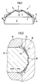
- a slotted valve according to the invention which bears the general reference number 1, is made up of a Membrane part 2 and a base part 3 together, which consist of different plastic materials.
- the membrane part 2 and the base part 3 are integrally connected to one another.
- the slit valve 1 accordingly represents a one-piece molded plastic part, which is produced by two-component injection molding in one work process, which will be discussed in more detail below in connection with FIG. 3.
- the slit valve 1 can have a rotationally symmetrical design
- the membrane part 2 can have an approximately frustoconical configuration with a peripheral wall region 4, along which the membrane part 2 is connected to a correspondingly tapered support wall 7 provided on the base part 3.
- the support wall 7 is provided on the upper side of the peripheral wall region 4 of the membrane part 2.
- a central wall area 5 of the membrane part 2 can freely deform like a rubber bellows.
- the central wall area 5 can further comprise a central zone 6, which can be turned inside out between a concave and a convex position and in the middle of which a slit-shaped pouring opening 10 is provided.
- the slot-shaped pouring opening 10 is closed in the concave position of the central zone 6 shown and opens when the central zone 6 is brought into the convex configuration under a pressure acting on it from the inside.
- the slit-shaped pouring opening 10 can be designed in the form of a short, simple incision. However, it can also represent an incision in the shape of a cross or the like.
- the slot-shaped pouring opening 10 is due to the rubber-elastic properties of the material from which the Membrane part 2 is closed when the membrane part 2 is in the position shown in FIG. 1 with a concave central zone 6.
- the slit-shaped pouring opening 10 remains closed as long as a pressure acting on the central zone 6 from the inside does not exceed a certain limit value.
- the limit value can be determined by suitable dimensioning of the membrane part 2 such that it is higher than the gradient pressure of a liquid in a container which is to be closed by a slit valve 1 according to the invention, so that an additional pressure is exerted on the container by hand must be to release the pouring opening 10.
- the base part 3 comprises a mounting flange 8 which extends radially outwards and an axially downwardly projecting sealing cone 9 which is dimensioned such that it can engage sealingly in an opening of a container, cf. Fig. 2.
- the preferred material for the membrane part 2 is a thermoplastic elastomer, such as that available under the type designation TC3-ABA from Kunststoffwerk Kraiburg GmbH + Co./D-84478 Waldkraiburg, can be obtained.
- Suitable materials for the base part 3 are in particular polyolefins, for example polypropylene. It was found that thermoplastic elastomer material for the membrane part 2 and polypropylene for the base part 3 can be easily integrally connected to form a one-piece molded part by two-component injection molding. If desired, however, the base part 3 could also consist of another thermoplastic material which is suitable for forming an integral connection with a thermoplastic elastomer material.
- FIG. 3 schematically shows a mold for two-component injection molding.
- a molding space is indicated at 32 indicated by hatched lines, which corresponds to the configuration of the base part 3 of the slit valve.
- An axially movable middle part 33 of the molding tool 31 can be brought into an advanced position, as indicated by the arrows A, B in FIG. 3, in which its end face contoured according to the contour of the membrane part 2 in contact with the correspondingly contoured end face one comes central area of the other mold 30, so that a mold space indicated at 34 by cross-hatched lines, which corresponds to the configuration of the membrane part 2, is closed.
- the molding space 34 extends partially into the molding space 32.
- the thermoplastic material for forming the base part 3 is introduced into the mold space 32 via an injection opening (not shown) in a first mold filling process.
- the axially movable middle part 33 of the mold 31 is pulled back until it stops, so that the mold space 34 is formed for the shaping of the membrane part 2.
- the plastic material for the membrane part 2 is then introduced into the molding space 34 via a further injection opening (not shown) in a second molding process and then allowed to solidify.
- the plastic material of the membrane part 2 comes into contact with that of the base part 3 along the aforementioned circumferential wall areas 4, 7, and the two plastic materials are virtually welded to one another, so that an integral, firm connection is achieved.
- the molds 30, 31 are moved apart to demould the two-component molded part formed.
- the slit-shaped pouring opening 10 can be introduced into the central zone 6 of the membrane part 2 by means of a cutting tool.
- FIG. 2 shows a slit valve arrangement with a slit valve described above and shown in FIG. 1 after assembly on a container neck 11, the sealing cone 9 of the slit valve 1 sealingly engaging in the opening 12 of the container neck 11.
- the flange 8 of the slit valve 1 can rest on the upper edge surface 13 of the container neck 11.
- the screw fastening element 14 can have a clamping area 15 which engages with its underside 16 when the screw fastening element 14 is screwed onto the container neck 11 with the flange 8 of the slit valve 1, so that the mounting flange 8 between the upper edge surface 13 of the container neck 11 and the lower surface 16 of the clamping area 15 of the screw fastening element 14 is clamped in a sealing manner.
- an element of this type which can be fitted in a snap fit could also be provided.
- a cover 17 can also be integrally articulated via a hinge, as is indicated at 18.
- the cover 17 can have a central bulge 19 projecting downwards, the configuration of which is that the central zone 6 of the membrane part 2 is adapted in the concave position and creates an additional closing function for the slit-shaped pouring opening 10 of the membrane part 2.
- the cover 17 can be held in the closed position by a snug fit on the screw fastening element 14 and can have a nose 20, with the aid of which it can be pivoted into the release position.
- the container neck 11 can either be an integral part of a container or, as is indicated in Fig. 2, represent a separate plastic molded part 21 which can be suitably, e.g. by gluing or heat sealing, can be connected to the container 22.
- the plastic molded part 21 can be made of a material with a higher dimensional stability than that of the container 22, so that the container 22 can, if desired, be designed as a flexible bag.
- the slit valve according to the invention could also be fitted to a container opening, e.g. be permanently attached by gluing, heat sealing or by snap fit, omitting a screw fastening element.
- the slit valve element can be adapted to any container and container opening configuration, so that the rotationally symmetrical design of the slit valve element is only exemplary.
- the invention was previously described with the aid of a slit valve as a separate component for detachable or permanent mounting on a container opening or closure cap.
- the slit valve could also be an integral part of a closure cap, in that it is formed as a one-piece molded part with the membrane part by two-component injection molding analogously to the previously described production of the slit valve.
- FIG. 4 shows a modified slotted valve arrangement with a slotted valve 1 and a screw fastening element 14 for fixing the slotted valve to a container (not shown).
- the arrangement differs from that previously described in connection with FIG. 2 essentially in that a sealing ring or sealing cone 20 is formed on the cover part 17.
- the sealing ring 20 engages in an opening 21 of the slot valve, which is defined by the support wall 7 of the base part 3.
- the support wall 7 is accordingly extended compared to the embodiment of the slot valve of FIG. 1.
- the area of the membrane part 2 which has the pouring opening is exposed and can be pushed through the sealing ring 20 into the concave position shown.
- the arrangement according to FIG. 4 is characterized by a further improved sealing function compared to the arrangement according to FIG. 2.
- FIG. 2 With regard to the other structural parts, reference can be made to FIG. 2 and the associated description.
Abstract
Description
Die Erfindung betrifft ein Schlitzventil zum Verschliessen einer Behälteröffnung und insbesondere ein Schlitzventil mit einem eine selbstdichtende schlitzförmige Ausgiessöffnung enthaltenden Membranteil mit gummielastischer Eigenschaft.The invention relates to a slit valve for closing a container opening and in particular to a slit valve with a membrane part containing a self-sealing slit-shaped pouring opening and having a rubber-elastic property.
Bekannt ist es (FR-C-673 584, EP-B-395 380), das Schlitzventil aus einem Kautschuk- oder Silikongummimaterial separat zu formen und mit einem Behälter mechanisch dauerhaft zu verbinden, indem ein rohrförmiger Bereich des Behälters um eine flanschförmige Erweiterung des Schlitzventiles herumgebördelt wird. Bis zum gebrauchsfähigen Einsatz des Schlitzventiles sind daher eine Reihe von Formungs- und Montagevorgängen erforderlich, die das einsatzfertige Produkt entsprechend verteuern. Ferner sind aufgrund der notwendigen gummielastischen Eigenschaft des Materials, aus dem das Schlitzventil geformt ist, Einschränkungen hinsichtlich der Formgebung hinzunehmen, und erfordert eine ausreichende Abdichtun, dass die Montagearbeit mit entsprechender Sorgfalt ausgeführt wird. Bekannt (EP-A-586 778) sind ferner vorgefertigte Schlitzventile mit Dichtflansch, die ebenfalls gänzlich aus einem der vorgenannten Materialien bestehen und mittels eines Kappenbefestigungsteiles an einer Behälteröffnung positioniert werden können.It is known (FR-C-673 584, EP-B-395 380) to separately form the slit valve from a rubber or silicone rubber material and to mechanically permanently connect it to a container by adding a flange-shaped extension of the container to the container Slit valve is flanged around. Until the slotted valve is ready for use, a series of molding and assembly processes are required, which make the ready-to-use product more expensive. Furthermore, due to the necessary rubber-elastic property of the material from which the slit valve is formed, restrictions regarding the shaping have to be accepted and a sufficient seal is required that the assembly work is carried out with appropriate care. Also known (EP-A-586 778) are prefabricated slit valves with a sealing flange, which likewise consist entirely of one of the aforementioned materials and can be positioned at a container opening by means of a cap fastening part.
Ein Ziel der Erfindung ist es, ein mit geringem Montageaufwand zum Verschliessen einer Behälteröffnung einsetzbares Schlitzventil der gattungsgemässen Art zu schaffen, das in wirtschaftlicher Weise gefertigt werden kann. Ein weiteres Ziel der Erfindung ist es, ein Schlitzventil mit verbesserter Gebrauchseigenschaft zu schaffen, indem es hinsichtlich seiner Öffnungs- und Schliessfunktion unabhängig von seinen der Montage dienenden Merkmalen optimiert werden kann.An object of the invention is to provide a slotted valve of the generic type which can be used to close a container opening with little assembly effort and which can be manufactured economically. Another object of the invention is to provide a slotted valve with improved performance by being able to be optimized with regard to its opening and closing functions regardless of its assembly-related features.
Diese und andere Ziele werden erfindungsgemäss durch ein Schlitzventil erreicht, welches einen eine schlitzförmige Ausgiessöffnung enthaltenden Membranteil umfasst, der aus einem thermoplastischen Elastomermaterial besteht und mit einem Basisteil aus einem thermoplastischen Kunststoffmaterial, das von dem thermoplastischen Elastomermaterial verschieden ist, integral verbunden ist.These and other objectives are achieved according to the invention by a slit valve which comprises a membrane part containing a slit-shaped pouring opening, which consists of a thermoplastic elastomer material and is integrally connected to a base part made of a thermoplastic material which is different from the thermoplastic elastomer material.
Danach stellt das Schlitzventil nach der Erfindung ein Formteil dar, das in einem Arbeitsgang durch Zweikomponenten-Spritzgiessen geformt wird, wie es grundsätzlich z.B. aus der FR-A-2 661 127 bekannt ist. Die unterschiedlichen Kunststoffmaterialien für den Membranteil und den Basisteil werden hierbei integral miteinander verbunden, so dass Ergebnis des Formungsvorganges ein im wesentlichen einsatzfertiges Produkt ist, bei dem lediglich die schlitzförmige Ausgiessöffnung durch einen anschliessenden Schneidvorgang in den Membranteil eingebracht werden muss. Die Kombination eines elastomeren Membranteiles mit einem Basisteil aus einem formstabileren Kunststoffmaterial ermöglicht es, dass das Schlitzventil als einsatzfertiges Bauelement bereitgestellt werden kann. Der Basisteil kann z.B. als Verschlusskappe geformt sein, in der der Membranteil ein integraler Bestandteil darstellt.Thereafter, the slit valve according to the invention is a molded part which is molded in one operation by two-component injection molding, as is basically known, for example, from FR-A-2 661 127. The different plastic materials for the membrane part and the base part are integrally connected to one another, so that the result of the molding process is an essentially ready-to-use product, in which only the slit-shaped pouring opening has to be introduced into the membrane part by a subsequent cutting process. The combination of an elastomeric membrane part with a base part made of a dimensionally stable plastic material enables the slit valve to be provided as a ready-to-use component. The base part can be shaped, for example, as a closure cap, in which the membrane part is an integral part.
Gemäss einem anderen Aspekt der Erfindung umfasst eine Schlitzventilanordnung zum Verschliessen einer Behälteröffnung ein Schlitzventil mit einem eine schlitzförmige Ausgiessöffnung enthaltenden Membranteil aus einem thermoplastischen Elastomermaterial, der mit einem Basisteil aus einem thermoplastischen Kunststoffmaterial, das vom thermoplastischen Elastomermaterial verschieden ist, integral verbunden ist, und ein an einem Behälterteil montierbares Befestigungselement zur Fixierung des Schlitzventiles am Behälterteil mit einem integral angelenkten Deckelteil, der zwischen einer Freigabe- und Schliesstellung schwenkbar ist, und einem am Deckelteil angeformten Dichtring zur Eingriffnahme in der Schliesstellung des Deckelteiles mit einer Öffnung im Basisteil des Schlitzventiles, an der ein Bereich des Membranteiles, der die Ausgiessöffnung enthält, freiliegt.According to another aspect of the invention, a slit valve arrangement for closing a container opening comprises a slit valve with a membrane part made of a thermoplastic elastomer material and containing a slit-shaped pouring opening, which is integrally connected to a base part made of a thermoplastic material, which is different from the thermoplastic elastomer material, and one a container part mountable fastening element for fixing the slit valve to the container part with an integrally articulated lid part which can be pivoted between a release and closed position, and a sealing ring formed on the lid part for engagement in the closed position of the lid part with an opening in the base part of the slit valve at which a Area of the membrane part that contains the pouring opening is exposed.
Die Erfindung wird nachfolgend anhand von Ausführungsformen und der Zeichnung näher erläutert. Es zeigen:
- Fig. 1 in geschnittener Ansicht ein erfindungsgemäss aufgebautes Schlitzventil,
- Fig. 2 eine Schlitzventilanordnung mit einem Schlitzventil nach Fig. in Verbindung mit dessen Montage an einer Behälteröffnung,
- Fig. 3 in fragmentarischer geschnittener Ansicht ein Formwerkzeug für das Zweikomponentenspritzgiessen des Schlitzventiles, und
- Fig. 4 eine Schlitzventilanordnung mit einem Schlitzventil gemäss einer modifizierten Ausführungsform der Erfindung.
- 1 is a sectional view of a slit valve constructed according to the invention,
- 2 shows a slotted valve arrangement with a slotted valve according to FIG. 1 in connection with its mounting on a container opening,
- Fig. 3 is a fragmentary sectional view of a mold for the two-component injection molding of the slit valve, and
- Fig. 4 shows a slit valve arrangement with a slit valve according to a modified embodiment of the invention.
Nach Fig. 1 setzt sich ein Schlitzventil nach der Erfindung, welches das allgemeine Bezugszeichen 1 trägt, aus einem Membranteil 2 sowie einem Basisteil 3 zusammen, die aus unterschiedlichen Kunststoffmaterialien bestehen. Der Membranteil 2 und der Basisteil 3 sind integral miteinander verbunden. Das Schlitzventil 1 stellt demzufolge ein einstückiges Kunststofformteil dar, welches durch Zweikomponentenspritzgiessen in einem Arbeitsvorgang hergestellt wird, worauf nachfolgend in Verbindung mit Fig. 3 näher eingegangen wird.1, a slotted valve according to the invention, which bears the
Das Schlitzventil 1 kann eine rotationssymmetrische Ausbildung haben, wobei der Membranteil 2 eine annähernd kegelstumpfförmige Konfiguration mit einem Umfangswandbereich 4 haben kann, längs dem der Membranteil 2 mit einer am Basisteil 3 vorgesehenen entsprechend kegelig verlaufenden Stützwand 7 in Verbindung steht. Bei der in Fig. 1 gezeigten Ausführungsform des Schlitzventiles 1 ist die Stützwand 7 oberseitig des Umfangswandbereiches 4 des Membranteiles 2 vorgesehen. Sie kann jedoch, wenn erwünscht, auch unterseitig angeformt sein, wie dies in Fig. 2 zu sehen ist. Ein zentraler Wandbereich 5 des Membranteiles 2 kann sich frei gummibalgartig verformen. Der zentrale Wandbereich 5 kann ferner eine zentrale Zone 6 umfassen, die zwischen einer konkaven und einer konvexen Position umgestülpt werden kann und in deren Mitte eine schlitzförmige Ausgiessöffnung 10 vorgesehen ist.The
Die schlitzförmige Ausgiessöffnung 10 ist in der gezeigten konkaven Position der zentralen Zone 6 geschlossen und öffnet sich, wenn die zentrale Zone 6 unter einem von innen auf sie einwirkenden Druck in die konvexe Konfiguration gebracht wird. Die schlitzförmige Ausgiessöffnung 10 kann in Gestalt eines kurzen einfachen Einschnittes ausgebildet sein. Sie kann jedoch auch einen Einschnitt in Kreuzform oder dgl. darstellen.The slot-
Die schlitzförmige Ausgiessöffnung 10 ist aufgrund der gummielastischen Eigenschaften des Materials, aus dem der Membranteil 2 besteht, geschlossen, wenn sich der Membranteil 2 in der in Fig. 1 gezeigten Position mit konkaver zentraler Zone 6 befindet. Die schlitzförmige Ausgiessöffnung 10 bleibt geschlossen, solange ein auf die zentrale Zone 6 von innen einwirkender Druck einen bestimmten Grenzwert nicht überschreitet. Insbesondere kann der Grenzwert durch geeignete Dimensionierung des Membranteiles 2 so festgelegt werden, dass er höher als der Gefälledruck einer Flüssigkeit in einem Behälter ist, der durch ein Schlitzventil 1 nach der Erfindung verschlossen werden soll, so dass auf den Behälter ein zusätzlicher Druck von Hand ausgeübt werden muss, um die Ausgiessöffnung 10 freizugeben.The slot-
Der Basisteil 3 umfasst einen radial nach aussen sich erstreckenden Montageflansch 8 sowie einen axial nach unten abstehenden Dichtkonus 9, der so dimensioniert ist, dass er dichtend in eine Öffnung eines Behälters eingreifen kann, vgl. Fig 2.The
Obschon für das integrale Schlitzventil 1 nach der Erfindung andere Kunststoffmaterialien verwendet werden können, ist bevorzugtes Material für den Membranteil 2 ein thermoplastisches Elastomer, wie es z.B. unter der Typenbezeichnung TC3-ABA von der Firma Gummiwerk Kraiburg GmbH + Co./D-84478 Waldkraiburg, bezogen werden kann. Geeignete Materialien für den Basisteil 3 sind insbesondere Polyolefine, z.B. Polypropylen. Es wurde festgestellt, dass sich thermoplastisches Elastomermaterial für den Membranteil 2 und Polypropylen für den Basisteil 3 gut integral zu einem einstückigen Formteil durch Zweikomponentenspritzgiessen verbinden lassen. Wenn erwünscht, könnte der Basisteil 3 jedoch auch aus einem anderen thermoplastischen Kunststoffmaterial bestehen, das geeignet ist, mit einem theremoplastischen Elastomermaterial eine integrale Verbindung einzugehen.Although other plastic materials can be used for the integral slotted
Fig. 3 zeigt schmematisch ein Formwerkzeug für das Zweikomponentenspritzgiessen. Zwischen einem Paar zusammenwirkender Formwerkzeuge 30, 31 ist ein bei 32 durch schraffierte Linien angedeuteter Formraum gebildet, der der Konfiguration des Basisteiles 3 des Schlitzventiles entspricht. Ein axial beweglicher Mittelteil 33 des Formwerkzeuges 31 kann in eine vorgeschobene Stellung gebracht werden, wie dies durch die Pfeile A, B in Fig. 3 angedeutet ist, bei der seine der Kontur des Membranteiles 2 entsprechend konturierte Stirnfläche in Berührung mit der entsprechend konturierten Stirnfläche eines zentralen Bereiches des anderen Formwerkzeuges 30 kommt, so dass ein bei 34 durch kreuzschraffierte Linien angedeuteter Formraum, der der Konfiguration des Membranteiles 2 entspricht, geschlossen ist. Der Formraum 34 erstreckt sich teilweise in den Formraum 32.3 schematically shows a mold for two-component injection molding. Between a pair of
In der vorgeschobenen Stellung des Mittelteiles 33 wird in einem ersten Formfüllvorgang das thermoplastische Kunststoffmaterial für die Formung des Basisteiles 3 über eine nicht gezeigte Einspritzöffnung in den Formraum 32 eingegeben. Sobald das Kunststoffmaterial im Formraum 32 soweit abgekühlt ist, dass es eine ausreichende Formbeständigkeit hat, wird der axial bewegliche Mittelteil 33 des Formwerkzeuges 31 bis zu einem Anschlag zurückgezogen, so dass der Formraum 34 für die Formung des Membranteiles 2 gebildet wird. Über eine nicht gezeigte weitere Einspritzöffnung wird dann in einem zweiten Formungsvorgang das Kunststoffmaterial für den Membranteil 2 in den Formraum 34 eingegeben und anschliessend erstarren gelassen.In the advanced position of the
Beim Einspritzen in den Formraum 34 kommt das Kunststoffmaterial des Membranteiles 2 mit dem des Basisteiles 3 längs der vorerwähnten umfänglichen Wanfbereiche 4, 7 in Berührung, und werden die beiden Kunststoffmaterialien dabei quasi miteinander verschweisst, so dass eine integrale feste Verbindung zustande kommt.When injected into the
Nach Erstarren der Kunststoffmaterialien in den Formräumen 32 und 34 werden die Formwerkzeuge 30, 31 zur Entformung des gebildeten Zweikomponenten-Formteiles auseinander gefahren. In einem anschliessenden getrennten Arbeitsgang kann in die zentrale Zone 6 des Membranteiles 2 mittels eines Schneidwerkzeuges die schlitzförmige Ausgiessöffnung 10 eingebracht werden.After the plastic materials have solidified in the
Fig. 2 zeigt eine Schlitzventilanordnung mit einem das vorbeschriebene und in Fig. 1 gezeigte Schlitzventil nach Montage an einem Behälterhals 11, wobei der Dichtkonus 9 des Schlitzventiles 1 dichtend in die Öffnung 12 des Behälterhalses 11 eingreift. Der Flansch 8 des Schlitzventiles 1 kann dabei auf der oberen Randfläche 13 des Behälterhalses 11 aufliegen.FIG. 2 shows a slit valve arrangement with a slit valve described above and shown in FIG. 1 after assembly on a
Auf ein Aussengewinde am Behälterhals 11 ist ein Schraubbefestigungselement 14 aus einem geeigneten formbeständigen thermoplastischen Kunststoffmaterial, wie PE oder PP, aufgeschraubt, um die Position des Schlitzventiles 1 am Behälterhals 11 zu fixieren. Das Schraubbefestigungselement 14 kann einen Klemmbereich 15 haben, der mit seiner Unterseite 16 beim Aufschrauben des Schraubbefestigungselementes 14 auf den Behälterhals 11 mit dem Flansch 8 des Schlitzventiles 1 in Eingriff kommt, so dass der Montageflansch 8 zwischen der oberen Randfläche 13 des Behälterhalses 11 und der Unterfläche 16 des Klemmbereiches 15 des Schraubbefestigungselementes 14 dichtend eingespannt wird. Es versteht sich, dass anstelle eines Schraubbefestigungselementes 14 auch ein in Schnappsitz montierbares derartiges Element vorgesehen werden könnte.A
Am Schraubbefestigungselement 14 kann ferner ein Deckel 17 integral über ein Scharnier angelenkt sein, wie dies bei 18 angedeutet ist. Der Deckel 17 kann eine zentrale nach unten ragende Auswölbung 19 aufweisen, deren Konfiguration derjenigen der zentralen Zone 6 des Membranteiles 2 in der konkaven Stellung angepasst ist und eine zusätzliche Schliessfunktion für die schlitzförmige Ausgiessöffnung 10 des Membranteiles 2 schafft. Der Deckel 17 kann in der geschlossenen Position durch Rastsitz am Schraubbefestigungselement 14 gehalten sein und eine Nase 20 aufweisen, mit deren Hilfe er in die Freigabeposition geschwenkt werden kann.On the
Der Behälterhals 11 kann entweder integraler Bestandteil eines Behälters sein oder, wie es in Fig. 2 angedeutet ist, ein separates Kunststofformteil 21 darstellen, welches in geeigneter Weise, z.B. durch Kleben oder Heissversiegeln, mit dem Behälter 22 verbunden werden kann. Das Kunststofformteil 21 kann aus einem Material mit höherer Formbeständigkeit als die des Behälters 22 bestehen, so dass der Behälter 22, wenn erwünscht, als flexibler Beutel ausgebildet sein kann.The
Das Schlitzventil nach der Erfindung könnte auch in anderer als der vorbeschriebenen Weise an einer Behälteröffnung, z.B. durch Kleben, Heissversiegeln oder durch Schnappsitz, unter Weglassung eines Schraubbefestigungselementes permanent befestigt sein. Ferner kann das Schlitzventilelement an jede beliebige Behälter- und Behälteröffnungskonfiguration angepasst werden, so dass die rotationssymmetrische Ausbildung des Schlitzventilelementes nur beispielhaft ist.The slit valve according to the invention could also be fitted to a container opening, e.g. be permanently attached by gluing, heat sealing or by snap fit, omitting a screw fastening element. Furthermore, the slit valve element can be adapted to any container and container opening configuration, so that the rotationally symmetrical design of the slit valve element is only exemplary.
Vorausgehend wurde die Erfindung anhand eines Schlitzventiles als separates Bauteil zur lösbaren oder permanenten Montage an einer Behälteröffnung oder Verschlusskappe beschrieben. Das Schlitzventil könnte auch integraler Bestandteil einer Verschlusskappe sein, indem diese mit dem Membranteil durch Zweikomponentenspritzgiessen analog zur vorbeschriebenen Herstellung des Schlitzventiles als einstückiges Formteil ausgebildet wird.The invention was previously described with the aid of a slit valve as a separate component for detachable or permanent mounting on a container opening or closure cap. The slit valve could also be an integral part of a closure cap, in that it is formed as a one-piece molded part with the membrane part by two-component injection molding analogously to the previously described production of the slit valve.
Fig. 4 zeigt eine modifizierte Schlitzventilanordnung mit einem Schlitzventil 1 und einem Schraubbefestigungselement 14 zur Fixierung des Schlitzventiles an einem Behälter (nicht gezeigt). Die Anordnung unterscheidet sich von derjenigen, die in Verbindung mit Fig. 2 vorausgehend beschrieben wurde, im wesentlichen darin, dass am Deckelteil 17 ein Dichtring oder Dichtkonus 20 angeformt ist. In der in Fig. 4 gezeigten Schliesstellung des Deckelteiles 17 greift der Dichtring 20 in eine Öffnung 21 des Schlitzventiles ein, die durch die Stützwand 7 des Basisteiles 3 definiert ist. Die Stützwand 7 ist demzufolge gegenüber der Ausführungsform des Schlitzventiles nach Fig. 1 entsprechend verlängert. Im Bereich der Öffnung 21 liegt der die Ausgiessöffnung aufweisende Bereich des Membranteiles 2 frei und kann durch den Dichtring 20 in die gezeigte konkave Position gestülpt werden. Die Anordnung nach Fig. 4 zeichnet sich durch eine weiter verbesserte Dichtfunktion gegenüber der Anordnung nach Fig. 2 aus. Bezüglich der übrigen Aufbauteile kann auf Fig. 2 und die zugehörige Beschreibung verwiesen werden.4 shows a modified slotted valve arrangement with a slotted
Claims (10)
Applications Claiming Priority (2)
| Application Number | Priority Date | Filing Date | Title |
|---|---|---|---|
| DE29508151U | 1995-05-17 | ||
| DE29508151U DE29508151U1 (en) | 1995-05-17 | 1995-05-17 | Slit valve for closing containers |
Publications (2)
| Publication Number | Publication Date |
|---|---|
| EP0743259A1 true EP0743259A1 (en) | 1996-11-20 |
| EP0743259B1 EP0743259B1 (en) | 2001-10-17 |
Family
ID=8008148
Family Applications (1)
| Application Number | Title | Priority Date | Filing Date |
|---|---|---|---|
| EP96107292A Expired - Lifetime EP0743259B1 (en) | 1995-05-17 | 1996-05-08 | Slit valve for dosing containers |
Country Status (7)
| Country | Link |
|---|---|
| US (1) | US5743443A (en) |
| EP (1) | EP0743259B1 (en) |
| CZ (1) | CZ291555B6 (en) |
| DE (2) | DE29508151U1 (en) |
| DK (1) | DK0743259T3 (en) |
| ES (1) | ES2165450T3 (en) |
| PL (1) | PL180362B1 (en) |
Cited By (5)
| Publication number | Priority date | Publication date | Assignee | Title |
|---|---|---|---|---|
| US5927567A (en) * | 1996-11-12 | 1999-07-27 | Owens-Illinois Closure Inc. | Dispensing closure and method of making |
| WO1999037550A1 (en) | 1998-01-22 | 1999-07-29 | Rexam Smt | Manual self-closing distributor |
| WO2000066447A1 (en) | 1999-05-04 | 2000-11-09 | Georg Menshen Gmbh & Co. Kg | Slotted closing valve for openings of containers |
| US6409034B2 (en) * | 1998-07-21 | 2002-06-25 | Kunststoffwerk Kutterrer Gmbh & Co. | Hinged container cap |
| DE102013221706A1 (en) | 2013-10-25 | 2015-04-30 | Robert Bosch Gmbh | Method for the metered dispensing of liquid ingredients from a tubular bag and means for carrying out the method |
Families Citing this family (71)
| Publication number | Priority date | Publication date | Assignee | Title |
|---|---|---|---|---|
| FR2750676B1 (en) * | 1996-07-03 | 1998-10-16 | Oreal | DISPENSING HEAD OF A LIQUID CONSISTING PRODUCT WITH A VISCOUS COMPRISING AN ELASTIC CLOSING MEMBER AND DISPENSING ASSEMBLY THUS EQUIPPED |
| DE19621676A1 (en) * | 1996-05-30 | 1997-12-11 | Zeller Plastik Koehn Graebner | Sealing membrane |
| DE19626792C1 (en) * | 1996-07-03 | 1998-02-26 | Gore W L & Ass Gmbh | Method for producing a closure element in the form of a plastic injection-molded part and a closure element produced by this method |
| US5927566A (en) * | 1996-07-11 | 1999-07-27 | Aptargroup, Inc. | One-piece dispensing system and method for making same |
| FR2752820B1 (en) * | 1996-08-29 | 1998-09-25 | Oreal | DISTRIBUTION CAPSULE WITH IMPROVED SEALING |
| DE29703275U1 (en) * | 1997-02-25 | 1998-06-25 | Weener Plastik Gmbh Co Kg | Sealing membrane |
| JP3523021B2 (en) * | 1997-06-20 | 2004-04-26 | 株式会社吉野工業所 | Container |
| US6089418A (en) * | 1997-06-23 | 2000-07-18 | Crown Cork & Seal Technologies Corporation | Dispensing closure with pressure actuated valve |
| ID25801A (en) * | 1997-08-21 | 2000-11-02 | Seaquist Closures | DISTRIBUTION PACKAGES AND METHODS TO MAKE EXTRACT PACKAGES |
| EP1007318A1 (en) * | 1997-08-21 | 2000-06-14 | Structoform Spritzgiessen Anisotroper Strukturkomponenten Gmbh | Method for injection moulding, injection mould, injection moulding device and method for filling a main extruder from a secondary extruder |
| FR2771078B1 (en) * | 1997-11-14 | 2000-01-28 | Oreal | FLOW REDUCING MEMBER, ESPECIALLY FOR A CONTAINER CONTAINING A COSMETIC PRODUCT AND MANUFACTURING METHOD |
| US5971232A (en) * | 1998-06-03 | 1999-10-26 | Aptargroup, Inc. | Dispensing structure which has a pressure-openable valve retained with folding elements |
| US6029866A (en) * | 1998-09-29 | 2000-02-29 | Aptargroup, Inc. | Multiple injection, toggle-action dispensing structure |
| WO2000037327A1 (en) * | 1998-12-22 | 2000-06-29 | Tadashi Hagihara | Self-standing bag container equipped with vacuum and flow rate control functions |
| US6273128B1 (en) | 1999-08-11 | 2001-08-14 | Joseph R. Paczonay | Apparatus for controlling the flow of fluid |
| US6053194A (en) * | 1999-09-10 | 2000-04-25 | S. C. Johnson & Son, Inc. | Duckbilled check valves and methods of making and using same |
| US6290108B1 (en) | 2000-04-14 | 2001-09-18 | Seaquist Closures Foreign, Inc. | Dispensing system with an internal releasable shipping seal and an extended tip containing a pressure openable valve |
| US6401990B1 (en) | 2000-06-19 | 2002-06-11 | Seaquist Closures Foreign, Inc. | Finger-operable pump actuator with finger pad |
| US6481589B2 (en) | 2001-02-22 | 2002-11-19 | Seaquist Closures Foreign, Inc. | Non-dispensing closure |
| EP1254849A1 (en) * | 2001-05-01 | 2002-11-06 | François Charles Claes | Method for manufacturing a cover for a container |
| NL1018233C2 (en) * | 2001-06-07 | 2002-12-10 | Itsac Nv | Dispensing spout and cap assembly. |
| DE20115488U1 (en) * | 2001-09-20 | 2001-12-06 | Seaquist Loeffler Kunststoffwerk Gmbh | Dispensing closure for containers containing flowable goods |
| US6446844B1 (en) * | 2001-12-18 | 2002-09-10 | Seaquist Closures Foreign, Inc. | Closure with internal flow control for a pressure openable valve in an extendable/retractable nozzle |
| US6910607B2 (en) * | 2002-03-15 | 2005-06-28 | Crown Cork & Seal Technologies Corporation | Cover for dispensing closure with pressure actuated valve |
| US6672487B1 (en) | 2002-06-07 | 2004-01-06 | Owens-Illinois Closure Inc. | Fluid dispensing closure, package and method of manufacture |
| US7350669B2 (en) * | 2002-10-11 | 2008-04-01 | Novartis Ag | Closure device for flexible pouches |
| US20060249545A1 (en) * | 2003-05-07 | 2006-11-09 | Crown Packaging Technology Inc. | Valve closure |
| GB2402712B (en) * | 2003-06-13 | 2006-04-19 | Ten Cate Plasticum | Improvements relating to dispensing apparatus |
| US20040256348A1 (en) * | 2003-06-23 | 2004-12-23 | Sonoco Development, Inc. | Flex panel lid or cap |
| GB0319139D0 (en) * | 2003-08-14 | 2003-09-17 | T G Eakin Ltd | Ostomy/fistula bag |
| DE10358433B4 (en) * | 2003-12-13 | 2005-11-24 | Henkel Kgaa | Storage container and cap for a storage container |
| GB2414470A (en) * | 2004-05-26 | 2005-11-30 | V & A Marketing Ltd | Training cup having a slit valve |
| US7255250B2 (en) * | 2004-06-22 | 2007-08-14 | Owens-Illinois Closure Inc. | Dispensing closure, package and method of manufacture |
| US7152763B2 (en) * | 2004-07-08 | 2006-12-26 | Stull Technologies, Inc. | Container closure and method of assembly |
| EP1531130A1 (en) * | 2004-08-26 | 2005-05-18 | CROWN Packaging Technology, Inc | Valve retaining device |
| US8899449B2 (en) | 2004-09-09 | 2014-12-02 | Warren S. Daansen | Nozzle tip with slit valve for fluid dispenser |
| US20060049208A1 (en) * | 2004-09-09 | 2006-03-09 | Daansen Warren S | Slit valves and dispensing nozzles employing same |
| CN101107175B (en) * | 2004-11-05 | 2011-11-02 | 马克·斯蒂尔 | Package having a fluid actuated closure |
| US8613547B2 (en) * | 2004-11-05 | 2013-12-24 | Mark Steele | Packages having bubble-shaped closures |
| CA2819479A1 (en) * | 2004-11-21 | 2006-05-26 | David Mitchell Windmiller | Bottom fillable bottles and systems for charging the same |
| US20060113331A1 (en) * | 2004-11-30 | 2006-06-01 | Kranson Industries, Inc., D/B/A Tricorbraun | Molded collapsible blow dome apparatus and method |
| US7503469B2 (en) * | 2005-03-09 | 2009-03-17 | Rexam Closure Systems Inc. | Integrally molded dispensing valve and method of manufacture |
| US7731066B2 (en) * | 2005-08-04 | 2010-06-08 | Colgate-Palmolive Company | Closure |
| US7708035B2 (en) | 2005-11-21 | 2010-05-04 | David Mitchell Windmiller | Bottom fillable bottles and systems for charging the same |
| GB2433496B (en) * | 2005-12-22 | 2007-11-21 | Bapco Closures Res Ltd | Tamper evident drinking fitment |
| US7792359B2 (en) * | 2006-03-02 | 2010-09-07 | Sharp Laboratories Of America, Inc. | Methods and systems for detecting regions in digital images |
| DE102006028106A1 (en) * | 2006-06-19 | 2007-12-20 | Kühn, Hans | Flip-top closure for e.g. plastic bottle containing e.g. cosmetics, fruit juice, cleaning agent has soft plastic seal |
| EP2210024A4 (en) * | 2007-10-08 | 2013-09-18 | Jes Tougaard Gram | Elastomeric valve |
| US20090180716A1 (en) * | 2007-10-31 | 2009-07-16 | Mark Steele | Package handle |
| US8397957B2 (en) | 2010-01-06 | 2013-03-19 | Berry Plastics Corporation | Dispensing valve |
| US8608034B2 (en) | 2011-02-18 | 2013-12-17 | Berry Plastics Corporation | Dispensing valve |
| MX349377B (en) * | 2011-07-08 | 2017-07-25 | Steele Mark | Sanitary dispensing package. |
| CN102922756A (en) * | 2011-08-08 | 2013-02-13 | 宏碁股份有限公司 | Element and manufacturing method thereof |
| USD671359S1 (en) | 2011-11-16 | 2012-11-27 | David Windmiller | Top lid assembly for bottle |
| USD738732S1 (en) | 2011-11-30 | 2015-09-15 | Tc Heartland Llc | Bottle with cap |
| USD720622S1 (en) | 2011-11-30 | 2015-01-06 | Tc Heartland Llc | Bottle with cap |
| RU2014141620A (en) | 2012-03-16 | 2016-05-10 | Аптаргруп, Инк. | OUTLET VALVE |
| US9085399B2 (en) * | 2012-05-21 | 2015-07-21 | The Coca-Cola Company | Bag in box cleanable connector system |
| DE102013004926A1 (en) | 2013-03-22 | 2014-09-25 | Kautex Textron Gmbh & Co. Kg | The working fluid container |
| MX2016008926A (en) | 2014-01-08 | 2017-01-16 | Weener Plastics Netherlands B V | Closure assembly. |
| US9144532B1 (en) * | 2014-04-22 | 2015-09-29 | Ronald G. Renner | Inflatable baby pacifier with method |
| US9609969B1 (en) | 2014-07-23 | 2017-04-04 | Acorn Bay | Deformable elastomeric valve and valve assembly |
| NL2014225B1 (en) | 2015-02-03 | 2016-10-12 | Plasticum Netherlands B V | Dispensing closure with self-closing valve. |
| EP3280650B1 (en) | 2015-04-09 | 2020-01-15 | Mark Steele | Package having valve closure system |
| WO2017035037A1 (en) | 2015-08-21 | 2017-03-02 | Acorn Bay | Valve system |
| US10494164B2 (en) | 2016-03-09 | 2019-12-03 | Fifth Third Bank, an Ohio Banking | Dispensable containment vessel and dispensing system |
| US10392239B2 (en) * | 2016-07-29 | 2019-08-27 | Berry Plastics Corporation | Liquid dispenser |
| WO2018119066A1 (en) * | 2016-12-21 | 2018-06-28 | Stoneridge Kitchen & Bath Llc | Glue gun |
| US10836541B2 (en) | 2017-11-27 | 2020-11-17 | Gateway Plastics, Inc. | Valve for a dispensing container |
| EP3546386B1 (en) * | 2018-03-28 | 2020-09-02 | 3M Innovative Properties Company | Flip-top cap for dispensing a flowable dental substance |
| GB201820292D0 (en) * | 2018-12-13 | 2019-01-30 | Obrist Closures Switzerland | Flow control insert |
Citations (3)
| Publication number | Priority date | Publication date | Assignee | Title |
|---|---|---|---|---|
| EP0442379A2 (en) * | 1990-02-14 | 1991-08-21 | GUALA S.p.A. | A stopper for deformable containers, incorporating an elastic diaphragm dispenser with a self-closing orifice, and method for the manufacture thereof |
| US5271531A (en) * | 1991-01-14 | 1993-12-21 | Seaquist Closures, A Division Of Pittway Corp. | Dispensing closure with pressure-actuated flexible valve |
| EP0649795A2 (en) * | 1993-10-21 | 1995-04-26 | L'oreal | Dispensing assembly provided with a check valve |
Family Cites Families (10)
| Publication number | Priority date | Publication date | Assignee | Title |
|---|---|---|---|---|
| FR673584A (en) * | 1928-08-24 | 1930-01-16 | Improvements to self-closing shutters for crush tubes and other similar containers | |
| US4728006A (en) * | 1984-04-27 | 1988-03-01 | The Procter & Gamble Company | Flexible container including self-sealing dispensing valve to provide automatic shut-off and leak resistant inverted storage |
| US4749108A (en) * | 1986-12-19 | 1988-06-07 | The Procter & Gamble Company | Bimodal storage and dispensing package including self-sealing dispensing valve to provide automatic shut-off and leak-resistant inverted storage |
| US4991745A (en) * | 1989-04-25 | 1991-02-12 | Liquid Molding Systems, Inc. | Dispensing valve with trampoline-like construction |
| FR2661127B1 (en) * | 1990-04-23 | 1992-07-24 | Moulage Automatique Sa | METHOD FOR MOLDING BY BI-INJECTION A CAPSULE COMPRISING AN INSERT. |
| US5409144A (en) * | 1991-12-06 | 1995-04-25 | Liquid Molding Systems Inc. | Dispensing valve for packaging |
| DE69206120T2 (en) * | 1992-02-14 | 1996-07-04 | Procter & Gamble | Device comprising a container provided with a slit valve as a vent valve and a liquid contained in this container. |
| EP0586778A1 (en) * | 1992-09-10 | 1994-03-16 | The Procter & Gamble Company | Upright liquid containing system with self seal valve |
| US5632420A (en) * | 1993-11-03 | 1997-05-27 | Zeller Plastik, Inc. | Dispensing package |
| US5472122A (en) * | 1994-10-11 | 1995-12-05 | Appleby; Paul | Dispensing valve with venting |
-
1995
- 1995-05-17 DE DE29508151U patent/DE29508151U1/en not_active Expired - Lifetime
-
1996
- 1996-05-07 CZ CZ19961323A patent/CZ291555B6/en not_active IP Right Cessation
- 1996-05-08 EP EP96107292A patent/EP0743259B1/en not_active Expired - Lifetime
- 1996-05-08 PL PL96314118A patent/PL180362B1/en not_active IP Right Cessation
- 1996-05-08 DK DK96107292T patent/DK0743259T3/en active
- 1996-05-08 ES ES96107292T patent/ES2165450T3/en not_active Expired - Lifetime
- 1996-05-08 DE DE59607916T patent/DE59607916D1/en not_active Expired - Lifetime
- 1996-05-14 US US08/645,705 patent/US5743443A/en not_active Expired - Lifetime
Patent Citations (3)
| Publication number | Priority date | Publication date | Assignee | Title |
|---|---|---|---|---|
| EP0442379A2 (en) * | 1990-02-14 | 1991-08-21 | GUALA S.p.A. | A stopper for deformable containers, incorporating an elastic diaphragm dispenser with a self-closing orifice, and method for the manufacture thereof |
| US5271531A (en) * | 1991-01-14 | 1993-12-21 | Seaquist Closures, A Division Of Pittway Corp. | Dispensing closure with pressure-actuated flexible valve |
| EP0649795A2 (en) * | 1993-10-21 | 1995-04-26 | L'oreal | Dispensing assembly provided with a check valve |
Cited By (11)
| Publication number | Priority date | Publication date | Assignee | Title |
|---|---|---|---|---|
| US5927567A (en) * | 1996-11-12 | 1999-07-27 | Owens-Illinois Closure Inc. | Dispensing closure and method of making |
| US6673295B1 (en) | 1996-11-12 | 2004-01-06 | Owens-Illinois Closure Inc. | Method of making a dispensing closure |
| US7041246B2 (en) | 1996-11-12 | 2006-05-09 | Owens-Illinois Closure Inc. | Method of making a dispensing closure |
| WO1999037550A1 (en) | 1998-01-22 | 1999-07-29 | Rexam Smt | Manual self-closing distributor |
| CN1091732C (en) * | 1998-01-22 | 2002-10-02 | 雷克斯姆Smt公司 | Manual self-closing distributor |
| US6497346B1 (en) | 1998-01-22 | 2002-12-24 | Rexam Smt | Self-closing manual dispenser |
| US6409034B2 (en) * | 1998-07-21 | 2002-06-25 | Kunststoffwerk Kutterrer Gmbh & Co. | Hinged container cap |
| WO2000066447A1 (en) | 1999-05-04 | 2000-11-09 | Georg Menshen Gmbh & Co. Kg | Slotted closing valve for openings of containers |
| US6450375B1 (en) | 1999-05-04 | 2002-09-17 | Georg Menshen Gmbh & Co. Kg | Slotted closing valve for openings of containers |
| DE102013221706A1 (en) | 2013-10-25 | 2015-04-30 | Robert Bosch Gmbh | Method for the metered dispensing of liquid ingredients from a tubular bag and means for carrying out the method |
| US10293355B2 (en) | 2013-10-25 | 2019-05-21 | Robert Bosch Gmbh | Method for dispensing liquid ingredients from a tubular bag in a metered manner, and means for carrying out the method |
Also Published As
| Publication number | Publication date |
|---|---|
| DE59607916D1 (en) | 2001-11-22 |
| ES2165450T3 (en) | 2002-03-16 |
| CZ291555B6 (en) | 2003-04-16 |
| PL314118A1 (en) | 1996-11-25 |
| DK0743259T3 (en) | 2002-02-04 |
| CZ132396A3 (en) | 1997-01-15 |
| PL180362B1 (en) | 2001-01-31 |
| DE29508151U1 (en) | 1995-08-17 |
| US5743443A (en) | 1998-04-28 |
| EP0743259B1 (en) | 2001-10-17 |
Similar Documents
| Publication | Publication Date | Title |
|---|---|---|
| EP0743259B1 (en) | Slit valve for dosing containers | |
| EP0210587B1 (en) | Method of manufacturing an upholstery element and apparatus for carrying out this method | |
| EP0111798B1 (en) | Automatic closure for a flexible container | |
| DE69722463T2 (en) | DISCHARGE SEAL WITH STOPPER AND METHOD FOR THE PRODUCTION THEREOF | |
| DE1206353B (en) | Plastic container and process for its manufacture | |
| EP2711307B1 (en) | Lid of a container | |
| DE2310230A1 (en) | FORMABLE PLASTIC ARTICLE AND PROCESS FOR ITS MANUFACTURING | |
| DE19926997A1 (en) | Relief valve for a vehicle ventilation system and injection molding process in which a rigid housing and flexible flap are molded in a multi-cavity tool whose plates move relative to each other | |
| EP0736406B1 (en) | Trough body | |
| EP1194342B1 (en) | Two-part plastic snap hinge closure | |
| EP2097329A1 (en) | Semi-finished product for producing an opening apparatus | |
| WO1992011123A1 (en) | Removable insert for casting moulds and mould for producing castings | |
| EP0642451B1 (en) | Plastic closure and method for its production | |
| DE4033963A1 (en) | Cable junction box with lid and gasket - has plastics box and thermoplastic rubber gasket injection moulded at box aperture edge | |
| EP3098048B1 (en) | Flap lock | |
| DE4412907C1 (en) | Plastics delivery tube | |
| DE60309663T2 (en) | "PROCESS FOR PROVIDING A JOINT WARRANTY CLOSURE, JOINT WARRANTY CLOSURE AND CONTAINER WITH A JOINT WARRANTY CLOSURE" | |
| EP0224702B1 (en) | Shaped plastic article incorporating surface-formed or inserted rubber-elastic parts | |
| EP2069216B1 (en) | Closure device for a packaging bag, and pack with a closure device | |
| DE2609026C3 (en) | Process for the production, filling and sealing of a container made of thermoplastic material and a valve provided with a multi-part filling and emptying nozzle for carrying out the process | |
| DE102008031171B4 (en) | Valve | |
| EP0002656B1 (en) | Method of manufacturing motor car accessory equipment from plastics and products thereby obtained | |
| EP3381487B1 (en) | Insert piece for a medical infusion system | |
| DE4315697C1 (en) | Self-closing closure for tubes and bottles | |
| DE602004008232T2 (en) | Drinking cap for beverage containers |
Legal Events
| Date | Code | Title | Description |
|---|---|---|---|
| PUAI | Public reference made under article 153(3) epc to a published international application that has entered the european phase |
Free format text: ORIGINAL CODE: 0009012 |
|
| AK | Designated contracting states |
Kind code of ref document: A1 Designated state(s): BE DE DK ES FR GB IT NL SE |
|
| 17P | Request for examination filed |
Effective date: 19970426 |
|
| 17Q | First examination report despatched |
Effective date: 19991004 |
|
| GRAG | Despatch of communication of intention to grant |
Free format text: ORIGINAL CODE: EPIDOS AGRA |
|
| GRAG | Despatch of communication of intention to grant |
Free format text: ORIGINAL CODE: EPIDOS AGRA |
|
| GRAH | Despatch of communication of intention to grant a patent |
Free format text: ORIGINAL CODE: EPIDOS IGRA |
|
| GRAH | Despatch of communication of intention to grant a patent |
Free format text: ORIGINAL CODE: EPIDOS IGRA |
|
| GRAA | (expected) grant |
Free format text: ORIGINAL CODE: 0009210 |
|
| AK | Designated contracting states |
Kind code of ref document: B1 Designated state(s): BE DE DK ES FR GB IT NL SE |
|
| REF | Corresponds to: |
Ref document number: 59607916 Country of ref document: DE Date of ref document: 20011122 |
|
| REG | Reference to a national code |
Ref country code: GB Ref legal event code: IF02 |
|
| GBT | Gb: translation of ep patent filed (gb section 77(6)(a)/1977) |
Effective date: 20011227 |
|
| REG | Reference to a national code |
Ref country code: DK Ref legal event code: T3 |
|
| ET | Fr: translation filed | ||
| REG | Reference to a national code |
Ref country code: ES Ref legal event code: FG2A Ref document number: 2165450 Country of ref document: ES Kind code of ref document: T3 |
|
| PLBE | No opposition filed within time limit |
Free format text: ORIGINAL CODE: 0009261 |
|
| STAA | Information on the status of an ep patent application or granted ep patent |
Free format text: STATUS: NO OPPOSITION FILED WITHIN TIME LIMIT |
|
| 26N | No opposition filed | ||
| PGFP | Annual fee paid to national office [announced via postgrant information from national office to epo] |
Ref country code: NL Payment date: 20040518 Year of fee payment: 9 |
|
| PGFP | Annual fee paid to national office [announced via postgrant information from national office to epo] |
Ref country code: SE Payment date: 20040524 Year of fee payment: 9 |
|
| PGFP | Annual fee paid to national office [announced via postgrant information from national office to epo] |
Ref country code: DK Payment date: 20040525 Year of fee payment: 9 Ref country code: BE Payment date: 20040525 Year of fee payment: 9 |
|
| PG25 | Lapsed in a contracting state [announced via postgrant information from national office to epo] |
Ref country code: IT Free format text: LAPSE BECAUSE OF NON-PAYMENT OF DUE FEES;WARNING: LAPSES OF ITALIAN PATENTS WITH EFFECTIVE DATE BEFORE 2007 MAY HAVE OCCURRED AT ANY TIME BEFORE 2007. THE CORRECT EFFECTIVE DATE MAY BE DIFFERENT FROM THE ONE RECORDED. Effective date: 20050508 |
|
| PG25 | Lapsed in a contracting state [announced via postgrant information from national office to epo] |
Ref country code: SE Free format text: LAPSE BECAUSE OF NON-PAYMENT OF DUE FEES Effective date: 20050509 |
|
| PG25 | Lapsed in a contracting state [announced via postgrant information from national office to epo] |
Ref country code: DK Free format text: LAPSE BECAUSE OF NON-PAYMENT OF DUE FEES Effective date: 20050531 Ref country code: BE Free format text: LAPSE BECAUSE OF NON-PAYMENT OF DUE FEES Effective date: 20050531 |
|
| BERE | Be: lapsed |
Owner name: GEORG *MENSHEN G.M.B.H. + CO. K.G. Effective date: 20050531 |
|
| PG25 | Lapsed in a contracting state [announced via postgrant information from national office to epo] |
Ref country code: NL Free format text: LAPSE BECAUSE OF NON-PAYMENT OF DUE FEES Effective date: 20051201 |
|
| EUG | Se: european patent has lapsed | ||
| NLV4 | Nl: lapsed or anulled due to non-payment of the annual fee |
Effective date: 20051201 |
|
| REG | Reference to a national code |
Ref country code: DK Ref legal event code: EBP |
|
| BERE | Be: lapsed |
Owner name: GEORG *MENSHEN G.M.B.H. + CO. K.G. Effective date: 20050531 |
|
| PGFP | Annual fee paid to national office [announced via postgrant information from national office to epo] |
Ref country code: GB Payment date: 20080514 Year of fee payment: 13 |
|
| GBPC | Gb: european patent ceased through non-payment of renewal fee |
Effective date: 20090508 |
|
| PG25 | Lapsed in a contracting state [announced via postgrant information from national office to epo] |
Ref country code: GB Free format text: LAPSE BECAUSE OF NON-PAYMENT OF DUE FEES Effective date: 20090508 |
|
| PGFP | Annual fee paid to national office [announced via postgrant information from national office to epo] |
Ref country code: DE Payment date: 20140430 Year of fee payment: 19 Ref country code: FR Payment date: 20140509 Year of fee payment: 19 Ref country code: ES Payment date: 20140411 Year of fee payment: 19 |
|
| REG | Reference to a national code |
Ref country code: DE Ref legal event code: R119 Ref document number: 59607916 Country of ref document: DE |
|
| REG | Reference to a national code |
Ref country code: FR Ref legal event code: ST Effective date: 20160129 |
|
| PG25 | Lapsed in a contracting state [announced via postgrant information from national office to epo] |
Ref country code: DE Free format text: LAPSE BECAUSE OF NON-PAYMENT OF DUE FEES Effective date: 20151201 |
|
| PG25 | Lapsed in a contracting state [announced via postgrant information from national office to epo] |
Ref country code: FR Free format text: LAPSE BECAUSE OF NON-PAYMENT OF DUE FEES Effective date: 20150601 |
|
| REG | Reference to a national code |
Ref country code: ES Ref legal event code: FD2A Effective date: 20160629 |
|
| PG25 | Lapsed in a contracting state [announced via postgrant information from national office to epo] |
Ref country code: ES Free format text: LAPSE BECAUSE OF NON-PAYMENT OF DUE FEES Effective date: 20150509 |