EP0732087A1 - Protective intraluminal sheath - Google Patents
Protective intraluminal sheath Download PDFInfo
- Publication number
- EP0732087A1 EP0732087A1 EP96301730A EP96301730A EP0732087A1 EP 0732087 A1 EP0732087 A1 EP 0732087A1 EP 96301730 A EP96301730 A EP 96301730A EP 96301730 A EP96301730 A EP 96301730A EP 0732087 A1 EP0732087 A1 EP 0732087A1
- Authority
- EP
- European Patent Office
- Prior art keywords
- sheath
- stent
- strand
- graft
- catheter
- Prior art date
- Legal status (The legal status is an assumption and is not a legal conclusion. Google has not performed a legal analysis and makes no representation as to the accuracy of the status listed.)
- Granted
Links
Images

Classifications
-
- A—HUMAN NECESSITIES
- A61—MEDICAL OR VETERINARY SCIENCE; HYGIENE
- A61F—FILTERS IMPLANTABLE INTO BLOOD VESSELS; PROSTHESES; DEVICES PROVIDING PATENCY TO, OR PREVENTING COLLAPSING OF, TUBULAR STRUCTURES OF THE BODY, e.g. STENTS; ORTHOPAEDIC, NURSING OR CONTRACEPTIVE DEVICES; FOMENTATION; TREATMENT OR PROTECTION OF EYES OR EARS; BANDAGES, DRESSINGS OR ABSORBENT PADS; FIRST-AID KITS
- A61F2/00—Filters implantable into blood vessels; Prostheses, i.e. artificial substitutes or replacements for parts of the body; Appliances for connecting them with the body; Devices providing patency to, or preventing collapsing of, tubular structures of the body, e.g. stents
- A61F2/95—Instruments specially adapted for placement or removal of stents or stent-grafts
- A61F2/962—Instruments specially adapted for placement or removal of stents or stent-grafts having an outer sleeve
- A61F2/97—Instruments specially adapted for placement or removal of stents or stent-grafts having an outer sleeve the outer sleeve being splittable
-
- A—HUMAN NECESSITIES
- A61—MEDICAL OR VETERINARY SCIENCE; HYGIENE
- A61F—FILTERS IMPLANTABLE INTO BLOOD VESSELS; PROSTHESES; DEVICES PROVIDING PATENCY TO, OR PREVENTING COLLAPSING OF, TUBULAR STRUCTURES OF THE BODY, e.g. STENTS; ORTHOPAEDIC, NURSING OR CONTRACEPTIVE DEVICES; FOMENTATION; TREATMENT OR PROTECTION OF EYES OR EARS; BANDAGES, DRESSINGS OR ABSORBENT PADS; FIRST-AID KITS
- A61F2/00—Filters implantable into blood vessels; Prostheses, i.e. artificial substitutes or replacements for parts of the body; Appliances for connecting them with the body; Devices providing patency to, or preventing collapsing of, tubular structures of the body, e.g. stents
- A61F2/95—Instruments specially adapted for placement or removal of stents or stent-grafts
- A61F2/958—Inflatable balloons for placing stents or stent-grafts
- A61F2002/9583—Means for holding the stent on the balloon, e.g. using protrusions, adhesives or an outer sleeve
-
- A—HUMAN NECESSITIES
- A61—MEDICAL OR VETERINARY SCIENCE; HYGIENE
- A61M—DEVICES FOR INTRODUCING MEDIA INTO, OR ONTO, THE BODY; DEVICES FOR TRANSDUCING BODY MEDIA OR FOR TAKING MEDIA FROM THE BODY; DEVICES FOR PRODUCING OR ENDING SLEEP OR STUPOR
- A61M25/00—Catheters; Hollow probes
- A61M25/10—Balloon catheters
- A61M2025/1043—Balloon catheters with special features or adapted for special applications
- A61M2025/1081—Balloon catheters with special features or adapted for special applications having sheaths or the like for covering the balloon but not forming a permanent part of the balloon, e.g. retractable, dissolvable or tearable sheaths
Definitions
- the invention relates generally to endoprostheses and, more specifically, to a sheath for protecting an intraluminal prosthesis and the patient when delivering and deploying the prosthesis to an area of a body lumen that has been weakened by damage or disease.
- the sheath of the present invention also is envisioned to be used with such prostheses as a graft for treating aneurysms of the abdominal aorta, or an intraluminal stent for repairing coronary arteries.
- abdominal aortic aneurysm is an abnormal dilation of the arterial wall of the aorta in the region of the aorta that passes through the abdominal cavity.
- the condition most commonly results from atherosclerotic disease.
- abdominal aortic aneurysms are dissecting aneurysms, that is aneurysms that are formed when there is a tear or fissure in the arterial lining or wall through which blood is forced and eventually clots, forming a thrombosis which swells and weakens the vessel.
- Abdominal aortic aneurysms do not cause pain, but are easily detected in a thorough physical examination. If the aneurysm is not detected and treated, it is likely to rupture and cause massive hemorrhaging fatal to the patient.
- Treatment of AAAs comprises some form of arterial reconstructive surgery which commonly is referred to as a "triple-A" procedure.
- One such method is by-pass surgery in which an incision is made into the abdominal cavity, the aorta is closed off above and below the site of the aneurysm, the aneurysm is resected, and a synthetic graft or tube sized to approximate the diameter of the normal aorta is sutured to the vessel to substitute for the area affected by the aneurysm and to allow blood flow through the aorta to be reestablished.
- the graft commonly is fabricated of a biocompatible material that is compliant and thin-walled. Nylons and synthetic fibers have been found to be suitable for the construction of the graft.
- the mortality rate associated with this surgical procedure is favorable (less than 5%) when it is performed prior to rupture of an aneurysm.
- patients having an AAA typically are over 65 years of age, and often have other chronic illnesses which increase the risk of peri-operative or post-operative complications. Those patients thus are not ideal candidates for this type of major surgery.
- this procedure is not often successfully resorted to after an aneurysm has ruptured (the mortality rate increases to over 65%), because of the extensiveness of the surgery and the time required to prepare a patient for it.
- This method also involves emplacement of a graft at the site of the aneurysm.
- the graft is deployed there by being routed through the vascular system carried by a catheter, wire or other device suitable for negotiating the vasculature.
- the graft and its deployment system often are introduced into the blood stream percutaneously with a femoral approach and the entire procedure can be performed using local rather than general anesthesia.
- the graft Once the graft has been positioned at the aneurysm, it is disengaged from the delivery system and can be affixed to the aortic wall both distally and proximally of the aneurysm.
- the graft is positioned in the vessel spanning the site of the aneurysm such that the walls of the graft generally are parallel to the walls of the affected area of the aorta.
- the aneurysm thus is excluded from the circulatory system by the graft, rather than being resected altogether. If the aneurysm is a dissecting type and a thrombosis exists between the walls of the aorta, the now-excluded aneurysm beneficially may provide structural support for the graft.
- Grafting systems often include an attachment system for deploying the graft.
- a tubular system often referred to as a stent, may be fitted coaxially within the graft, and which can extend out of the graft at either or both the proximal and distal ends thereof.
- the attachment system often has a lattice or open weave structure, which can provide flexibility and promote rapid endothelial tissue growth through the structure once the graft has been deployed.
- the attachment system may include hook-like elements for penetrating the intimal walls to attach the graft to the aorta, or those hook-like elements may be provided on the graft itself.
- the actual function of delivering the graft may be accomplished by inflating the balloon of a catheter by introducing pressurized fluid into a lumen of the catheter from a source external to the patient. Inflation of the balloon applies a force to the graft and any attachment system supplied therein which extends radially and presses the graft and attachment system into the vessel wall above and below the aneurysm.
- a protective capsule or sheath often is provided to protect and contain the graft until such time as deployment is desired.
- the sheath helps hold the graft and stents onto the catheter and prevent direct contact of the elements of the combination with the walls of the vessel while the system is being advanced to the treatment site, thus protecting the vascular system of the patient from hazardous protrusions such as sharp edges on the stents.
- a rod or wire may be connected to the sheath and extend proximally along the length of the catheter so that it can be manipulated by the physician exterior to the patient and retracted (proximally) at the time of deployment.
- the sheath can traverse the entire length of the catheter, and can be retracted (proximally) from outside the patient to expose the graft-and-stent combination.
- the manipulative elements of the sheath may be relatively bulky and awkward to use, and may interfere with the precise placement of the graft and with the operation of the graft delivery system.
- proximal is toward the outside of the patient and away from the stent and graft while reference to the “distal” is toward the stent and graft on the balloon portion of the catheter.
- distal is toward the stent and graft on the balloon portion of the catheter.
- the proximal and distal references apply to directions in the vascular system such as the aorta.
- PTCA Percutaneous transluminal coronary angioplasty
- a dilation catheter having an inflatable balloon is advanced through a patient's arterial system until the balloon crosses an atherosclerotic lesion.
- the balloon is inflated at a relatively high pressure so as to compress the atherosclerotic plaque of the lesion against the inside of the artery wall and dilate the artery.
- the balloon then is deflated to a small profile for removal from the vasculature of the patient, and blood flow resumes through the dilated artery.
- a physician can implant an intravascular prosthesis or stent to maintain vascular patency inside the artery at the lesion.
- the stent may be delivered to the lesion site by a balloon catheter which then expands the stent to a larger diameter.
- the stent is left in the artery, either temporarily or permanently, at the side of the dilated lesion.
- the stent may have protuberances on its outer surface facing the lumen wall of the patient. Should such protuberances rub against the lumen wall during delivery of the stent, the protuberances may damage the lumen wall and cause the stent to be displaced from the catheter.
- the sheath holds the stent onto the catheter and prevents the stent from damaging the lumen walls while the stent is being delivered to the treatment site, thus protecting the vascular system of the patient from any sharp edges on the stents.
- the manipulative elements of the sheath can be relatively bulky and awkward to use, and may interfere with the precise placement of the stent and with the operation of the catheter-stent delivery system.
- an improved sheath is desirable for preventing the stent surface (possibly including hooks on the stent) from abrading the vessel wall.
- the improved sheath should keep the stent properly centered over the balloon catheter delivery system as the graft is deployed in the vessel. It also would be useful to remove the sheath from the graft without disturbing the precise placement of the stent over the balloon so that the graft may be properly implanted in the vessel.
- sheath which holds the stent tightly against a balloon delivery catheter, wherein the catheter can be removed without disturbing the precise placement of the stent over the balloon.
- the sheath should also be capable of being used with a variety of implantable devices, including various catheter-stent-graft combinations, for delivery anywhere in the body.
- Embodiments of the present invention are directed to a sheath for use with catheter delivery systems for repairing diseased or injured vessels, and may be used for treating aneurysms.
- adxdimnts may be employed with a graft-and-stent combination for treating aneurysms, or an intraluminal stent for treating coronary artery diseases.
- the present invention should not be construed as being limited to those specific applications.
- the sheath can be used with various catheter-stent-graft combinations for delivery anywhere in the body, including the aorta and the coronary arteries. The sheath tightly packs the stent against the catheter shaft so that a low profile can be maintained while the combination is being routed to the treatment site.
- the stent-and-graft combination can be readily delivered to the aneurysm by mounting the combination on a balloon portion of a delivery catheter, and passing the assembly through the vasculature to the implantation site.
- a variety of means for securing the stent-and-graft combination to the catheter during delivery is available.
- the sheath includes a sheath body having an outer surface, a first sheath end and a second sheath end; a collar located at the second sheath end; and a strand having a first strand end located distally from the outer surface of the sheath from the collar to the first sheath end, and a free strand end extending from the first sheath end. Applying a proximal force on the free strand end causes the first strand end to cut through the sheath from the first end to the collar, wherein the collar is resistant to being cut by the first strand end.
- One feature of this embodiment is to prevent the rough stent surface from abrading the vessel wall.
- Another feature of this embodiment is to keep the stent properly centered over the balloon catheter delivery system as the graft is deployed in the vessel.
- Yet another feature of this embodiment is to remove the sheath from the graft without disturbing the precise placement of the stent over the balloon so that the graft may be properly implanted in the vessel.
- FIG. 1 is an elevational view, partially in section, of a preferred embodiment of the sheath according to the invention incorporated into a graft delivery system.
- FIG. 2 is an elevational view of the embodiment of the sheath shown in Fig. 1 after being split according to the invention.
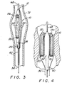
- FIG. 3 is an elevational view, partially in section, of another preferred embodiment of the sheath according to the invention.
- FIG. 4 is a sectional view of another preferred embodiment of the sheath according to the invention incorporated with a coronary stent delivery system disposed within an arterial region.
- Embodiments of the invention relate to a sheath which is used in conjunction with atraumatically inserted devices for repairing body lumens of all types.
- a stent-and-graft combination for repairing an aortic aneurysm.
- a intraluminal stent for repairing coronary arteries in conjunction with a preferred Embodiment.
- other devices may be equally suited to receive the sheath of the present invention.
- the graft delivery system includes a multilumen catheter 60 of the type used in other percutaneous procedures for deploying stents, grafts or other prostheses to repair portions of blood vessels.
- the operative end of catheter 60 includes a balloon for installing prostheses such as a stent-and-graft combination.
- Sheath 10 holds the graft and stent combination tightly onto the catheter, and assists in providing a small cross-profile for the combination.
- the stent is kept properly centered over the delivery catheter as the combination is pushed into place in the vessel.
- Sheath 10 has a smooth outer surface for protecting the vascular walls from the rough surfaces of stents and other prostheses.
- Sheath 10 is shown in Fig. 1 to cover the stent and graft, and may further extend to cover part of the catheter itself.
- the sheath may extend to cover substantially the entire length of the catheter.
- Sheath 10 may be any suitable length to maintain the stent in place over the catheter. Removal of the sheath from the above catheter-stent-graft combination may be effected by unzipping or splitting open the body of the sheath as will be discussed in more detail.
- Sheath 10 includes a notch 15 formed on one end and a collar 20 located on the opposite end of sheath 10.
- Collar 20 acts as a reinforcement at an end of sheath 10, and may be formed from a doubled-over portion of the sheath body.
- Strand 30 is a strong, thin, flexible, biocompatible thread or fiber filament that is connected to collar 20. Strand 30 is located away from the outer sheath surface, and travels from collar 20 to the notch 15 on the opposite end of sheath 10. Strand 30 may be embedded within the body of sheath 10, or placed underneath, between sheath 10 and the stent and graft combination. Strand 30 further includes a free end 34 extending away from sheath 10 at notch 15. The free end 34 of the strand doubles back past collar 20 towards the proximal end of the catheter.
- the body of sheath 10 is preferably composed of a PET ("polyethyleneterapthalate”) heatshrink material.
- PET is a preferable material because it is strong, thin, biocompatible, and tears easily after being notched.
- a suitable wall thickness for sheath 10 may be 0.127 millimeters (0.005 inches). However, those skilled in the art will recognize that other thicknesses are also suitable, depending upon the application and specific use of sheath 10.
- heatshrink techniques allows a device, such as a graft-and-stent combination, to be packed tightly against a catheter shaft to reduce the cross-profile of the device to be intraluminally inserted.
- Delivery catheter 60 is used to deploy tubular graft 52 at the site of abdominal aortic aneurysm 54 via stent 56.
- the catheter has a first lumen extending along its length which is in communication with an expandable member or balloon disposed at the distal end of the catheter. Pressurized fluid or gas can be introduced into the balloon lumen to inflate the balloon, and to exert an outward radial force on anything disposed about the balloon.
- the catheter has a second lumen through which guidewire 68 passes.
- the guidewire is advanced through the vasculature of a patient beyond the site of aneurysm as a preliminary step in the graft delivery procedure. After the guidewire 68 has been positioned, the catheter 60 carrying the sheathed stent-and-graft combination is advanced over the guidewire.
- the stent-and-graft combination is loaded onto the distal end of catheter 60.
- the combination is positioned so that stent 56 overlies balloon 62 and the graft rests over and is substantially coaxial with the catheter. It is important that the graft and stent remain in this position until the deployment function is accomplished.
- Sheath 10 can be removed without disturbing the precise placement of the stent 56 over the balloon by using the strand 30 to split open sheath 10 for facilitating its simple removal.
- Figs 1 and 2 show the sheath covering only the stent-and-graft combination, it should be noted that the invention is not so limited.
- Sheath 10 may extend beyond the stent-and-graft combination and further encompass the shaft of catheter 60. Sheath 10 is removed after being unzipped or split open.
- the free end 34 of strand 30 exits away from sheath 10 and extends proximally along the length of the catheter to where the free strand end 34 can be manipulated by a physician exterior to the patient. As shown in Fig.
- Collar 20 is resistent to the cutting force of strand 30.
- Collar 20 may be formed of any suitable material which is sufficiently resistant to the cutting force of strand 30 so as to act as a stop. As noted earlier, collar 20 may be a doubled segment of sheath material, or a separate plastic element. Notch 15 encourages the propagation of the split along sheath 10.
- strand 30 may be built into or embedded in an extrusion of the body of sheath 10. Such construction may take the form of a thickened path for the strand 30 along the wall of the sheath 10.
- a flaw 17 may be built into the sheath to encourage the propagation of a split. The flaw 17 is preferably a perforation formed in the body of sheath 10.
- Strand 30 may be configured in any suitable manner along the body of sheath 10 to create a desired split therealong. A plurality of strands may be used to create multiple splits in the sheath.
- sheath 10 is unzipped or split, stent 56 is no longer compressed against catheter 60, and sheath 10 can be pulled off from the stent and graft combination with relative ease. Continued traction on strand 30 tugs on collar 20 to remove the split sheath 10 from over the combination without disturbing the precise placement of the stent over the balloon catheter in the vessel.
- the sheath is withdrawn (proximally) to expose the stent and graft combination, and the catheter is advanced so that the stent and graft combination span the aneurysm.
- the entire sheath 10 can be pulled out of the patient without disturbing the placement of the stent-and-graft combination.
- the balloon 62 is inflated by the pressurized fluid or gas source external to the patient, and the radial forces accompanying expansion of the balloons are applied to expand both the graft and the stents radially outward, pressing both elements against aortic wall 72 proximal to and distal to the aneurysm.
- Attachment elements or hooks 57 are provided on stent 56 for attaching the stent-and-graft combination to the intima or aortic wall.
- sheath 10 instead of covering only a portion of the combination, sheath 10 alternately may be extended to entirely cover both the stent and the graft. Such an extended configuration would be advantageous for covering a combination where two stents 56 and 58 are used at opposite ends of the graft 52.
- Collar 20 may include a tough, biocompatible coaxial tube 22 surrounding the catheter shaft. Coaxial tube 22 surrounds a portion of the catheter shaft, and may extend to cover substantially the entire length of the catheter shaft. A cleft 24 may be found along a substantial length of coaxial tube 22 to form a split therealong in order to ease the removal of sheath 10 from along the shaft and operative end of catheter 60.
- Cleft 24 may be a fault similar to flaw 17 to be cut through by strand 30, or a preformed split in coaxial tube 22. In any event, cleft 24 does not span the entire length of coaxial tube 22.
- the free end 34 of strand 30 may be situated to travel within the circumference of coaxial tube 22 and alongside of the catheter.
- part of the strand could be located outside the sheath, or embedded near the outer surface of the sheath, so as to cut into the sheath body as proximal force is applied to the free end 34 of strand 30.
- Fig. 4 shows another embodiment of the invention used in combination with an intraluminal coronary stent 59 for treating coronary artery disease.
- PTCA treatment does not require the use of a graft.
- Sheath 10 is similar to that shown in the prior embodiments.
- Strand 30 is shown travelling underneath sheath 10, between the body of sheath 10 and the outer surface of coronary stent 59.
- the strand also may be embedded in an extrusion of the body of the sheath.
- a plurality of strands may be used to split the sheath for removal.
- a second strand 130 is shown in Fig. 4, which complements strand 30.
- the sheath can be used in other instances in other vessels of the body.
- the described sheath has the novel features of splitting the sheath by pulling on the remote free end of an otherwise embedded strand of thread so as to remove the sheath prior to implantation of the graft without disturbing the placement of the stent and graft configuration.
- This feature coupled with the fact that the sheath tightly holds the stent and graft combination against the balloon delivery catheter, provides highly desirable protection for various types of prostheses for endoluminal treatment.
- Other modifications and improvements such as varying the route of the strand within the sheath to split the sheath at two or more points or to keep the strand better contained within the sheath, may be made without departing from the scope of the invention.
Abstract
Description
- The invention relates generally to endoprostheses and, more specifically, to a sheath for protecting an intraluminal prosthesis and the patient when delivering and deploying the prosthesis to an area of a body lumen that has been weakened by damage or disease. The sheath of the present invention also is envisioned to be used with such prostheses as a graft for treating aneurysms of the abdominal aorta, or an intraluminal stent for repairing coronary arteries.
- An abdominal aortic aneurysm (AAA) is an abnormal dilation of the arterial wall of the aorta in the region of the aorta that passes through the abdominal cavity. The condition most commonly results from atherosclerotic disease. Frequently, abdominal aortic aneurysms are dissecting aneurysms, that is aneurysms that are formed when there is a tear or fissure in the arterial lining or wall through which blood is forced and eventually clots, forming a thrombosis which swells and weakens the vessel. Abdominal aortic aneurysms do not cause pain, but are easily detected in a thorough physical examination. If the aneurysm is not detected and treated, it is likely to rupture and cause massive hemorrhaging fatal to the patient.
- Treatment of AAAs comprises some form of arterial reconstructive surgery which commonly is referred to as a "triple-A" procedure. One such method is by-pass surgery in which an incision is made into the abdominal cavity, the aorta is closed off above and below the site of the aneurysm, the aneurysm is resected, and a synthetic graft or tube sized to approximate the diameter of the normal aorta is sutured to the vessel to substitute for the area affected by the aneurysm and to allow blood flow through the aorta to be reestablished. The graft commonly is fabricated of a biocompatible material that is compliant and thin-walled. Nylons and synthetic fibers have been found to be suitable for the construction of the graft. The mortality rate associated with this surgical procedure is favorable (less than 5%) when it is performed prior to rupture of an aneurysm. However, patients having an AAA typically are over 65 years of age, and often have other chronic illnesses which increase the risk of peri-operative or post-operative complications. Those patients thus are not ideal candidates for this type of major surgery. Further, it has been pointed out that this procedure is not often successfully resorted to after an aneurysm has ruptured (the mortality rate increases to over 65%), because of the extensiveness of the surgery and the time required to prepare a patient for it.
- Because of the aforementioned disadvantages to conventional surgical methods, another procedure was developed as an alternative to conventional, major surgery. This method also involves emplacement of a graft at the site of the aneurysm. The graft is deployed there by being routed through the vascular system carried by a catheter, wire or other device suitable for negotiating the vasculature. The graft and its deployment system often are introduced into the blood stream percutaneously with a femoral approach and the entire procedure can be performed using local rather than general anesthesia.
- Once the graft has been positioned at the aneurysm, it is disengaged from the delivery system and can be affixed to the aortic wall both distally and proximally of the aneurysm. The graft is positioned in the vessel spanning the site of the aneurysm such that the walls of the graft generally are parallel to the walls of the affected area of the aorta. The aneurysm thus is excluded from the circulatory system by the graft, rather than being resected altogether. If the aneurysm is a dissecting type and a thrombosis exists between the walls of the aorta, the now-excluded aneurysm beneficially may provide structural support for the graft.
- Grafting systems often include an attachment system for deploying the graft. A tubular system, often referred to as a stent, may be fitted coaxially within the graft, and which can extend out of the graft at either or both the proximal and distal ends thereof. The attachment system often has a lattice or open weave structure, which can provide flexibility and promote rapid endothelial tissue growth through the structure once the graft has been deployed. The attachment system may include hook-like elements for penetrating the intimal walls to attach the graft to the aorta, or those hook-like elements may be provided on the graft itself.
- The actual function of delivering the graft may be accomplished by inflating the balloon of a catheter by introducing pressurized fluid into a lumen of the catheter from a source external to the patient. Inflation of the balloon applies a force to the graft and any attachment system supplied therein which extends radially and presses the graft and attachment system into the vessel wall above and below the aneurysm. To avoid premature detachment of the graft and to prevent the attachment elements from damaging the vessels or halting the forward movement of the system while the graft is being routed to the treatment site, a protective capsule or sheath often is provided to protect and contain the graft until such time as deployment is desired.
- The sheath helps hold the graft and stents onto the catheter and prevent direct contact of the elements of the combination with the walls of the vessel while the system is being advanced to the treatment site, thus protecting the vascular system of the patient from hazardous protrusions such as sharp edges on the stents. A rod or wire may be connected to the sheath and extend proximally along the length of the catheter so that it can be manipulated by the physician exterior to the patient and retracted (proximally) at the time of deployment. Alternatively, the sheath can traverse the entire length of the catheter, and can be retracted (proximally) from outside the patient to expose the graft-and-stent combination. However, in either instance, the manipulative elements of the sheath may be relatively bulky and awkward to use, and may interfere with the precise placement of the graft and with the operation of the graft delivery system.
- As used herein, reference to the "proximal" is toward the outside of the patient and away from the stent and graft while reference to the "distal" is toward the stent and graft on the balloon portion of the catheter. The proximal and distal references apply to directions in the vascular system such as the aorta.
- It should be noted that sheaths are often used with other implantable devices, including intraluminal stents for delivery to the coronary artery. Percutaneous transluminal coronary angioplasty (PTCA) is a widely practiced procedure for treating coronary artery disease. In a typical PTCA procedure, a dilation catheter having an inflatable balloon is advanced through a patient's arterial system until the balloon crosses an atherosclerotic lesion. The balloon is inflated at a relatively high pressure so as to compress the atherosclerotic plaque of the lesion against the inside of the artery wall and dilate the artery. The balloon then is deflated to a small profile for removal from the vasculature of the patient, and blood flow resumes through the dilated artery. To help prevent abrupt closure, dissection, or restenosis, a physician can implant an intravascular prosthesis or stent to maintain vascular patency inside the artery at the lesion. The stent may be delivered to the lesion site by a balloon catheter which then expands the stent to a larger diameter. The stent is left in the artery, either temporarily or permanently, at the side of the dilated lesion.
- The stent may have protuberances on its outer surface facing the lumen wall of the patient. Should such protuberances rub against the lumen wall during delivery of the stent, the protuberances may damage the lumen wall and cause the stent to be displaced from the catheter. The sheath holds the stent onto the catheter and prevents the stent from damaging the lumen walls while the stent is being delivered to the treatment site, thus protecting the vascular system of the patient from any sharp edges on the stents. However, as noted above, the manipulative elements of the sheath can be relatively bulky and awkward to use, and may interfere with the precise placement of the stent and with the operation of the catheter-stent delivery system.
- In order for a stent to be used advantageously with the endoprosthesis systems described above for the treatment and repair of body lumen, an improved sheath is desirable for preventing the stent surface (possibly including hooks on the stent) from abrading the vessel wall. The improved sheath should keep the stent properly centered over the balloon catheter delivery system as the graft is deployed in the vessel. It also would be useful to remove the sheath from the graft without disturbing the precise placement of the stent over the balloon so that the graft may be properly implanted in the vessel. Although various sheaths have been proposed, none adequately provides all of these desirable features.
- What is needed in the art of such implantable devices is a sheath which holds the stent tightly against a balloon delivery catheter, wherein the catheter can be removed without disturbing the precise placement of the stent over the balloon. The sheath should also be capable of being used with a variety of implantable devices, including various catheter-stent-graft combinations, for delivery anywhere in the body.
- Embodiments of the present invention are directed to a sheath for use with catheter delivery systems for repairing diseased or injured vessels, and may be used for treating aneurysms. adxdimnts may be employed with a graft-and-stent combination for treating aneurysms, or an intraluminal stent for treating coronary artery diseases. In any event, the present invention should not be construed as being limited to those specific applications. The sheath can be used with various catheter-stent-graft combinations for delivery anywhere in the body, including the aorta and the coronary arteries. The sheath tightly packs the stent against the catheter shaft so that a low profile can be maintained while the combination is being routed to the treatment site.
- The stent-and-graft combination can be readily delivered to the aneurysm by mounting the combination on a balloon portion of a delivery catheter, and passing the assembly through the vasculature to the implantation site. A variety of means for securing the stent-and-graft combination to the catheter during delivery is available. Presently, it is preferred to compress the stent onto the balloon and retain the stent on the balloon using a protective sheath.
- In a preferred embodiment of the invention, the sheath includes a sheath body having an outer surface, a first sheath end and a second sheath end; a collar located at the second sheath end; and a strand having a first strand end located distally from the outer surface of the sheath from the collar to the first sheath end, and a free strand end extending from the first sheath end. Applying a proximal force on the free strand end causes the first strand end to cut through the sheath from the first end to the collar, wherein the collar is resistant to being cut by the first strand end.
- One feature of this embodiment is to prevent the rough stent surface from abrading the vessel wall.
- Another feature of this embodiment is to keep the stent properly centered over the balloon catheter delivery system as the graft is deployed in the vessel.
- Yet another feature of this embodiment is to remove the sheath from the graft without disturbing the precise placement of the stent over the balloon so that the graft may be properly implanted in the vessel.
- Other features and advantages of the present invention will become more apparent from the following detailed description of a preferred embodiment, when taken in conjunction with the accompanying exemplary drawings.
- FIG. 1 is an elevational view, partially in section, of a preferred embodiment of the sheath according to the invention incorporated into a graft delivery system.
- FIG. 2 is an elevational view of the embodiment of the sheath shown in Fig. 1 after being split according to the invention.
- FIG. 3 is an elevational view, partially in section, of another preferred embodiment of the sheath according to the invention.
- FIG. 4 is a sectional view of another preferred embodiment of the sheath according to the invention incorporated with a coronary stent delivery system disposed within an arterial region.
- Embodiments of the invention relate to a sheath which is used in conjunction with atraumatically inserted devices for repairing body lumens of all types. As described herein, reference is made to a stent-and-graft combination for repairing an aortic aneurysm. Reference will also be made to a intraluminal stent for repairing coronary arteries in conjunction with a preferred Embodiment. However, other devices may be equally suited to receive the sheath of the present invention.
- One preferred method of incorporating
sheath 10 of the preferred embodiment into a graft delivery system is illustrated in Fig. 1. The graft delivery system includes amultilumen catheter 60 of the type used in other percutaneous procedures for deploying stents, grafts or other prostheses to repair portions of blood vessels. The operative end ofcatheter 60 includes a balloon for installing prostheses such as a stent-and-graft combination.Sheath 10 holds the graft and stent combination tightly onto the catheter, and assists in providing a small cross-profile for the combination. The stent is kept properly centered over the delivery catheter as the combination is pushed into place in the vessel.Sheath 10 has a smooth outer surface for protecting the vascular walls from the rough surfaces of stents and other prostheses.Sheath 10 is shown in Fig. 1 to cover the stent and graft, and may further extend to cover part of the catheter itself. The sheath may extend to cover substantially the entire length of the catheter.Sheath 10 may be any suitable length to maintain the stent in place over the catheter. Removal of the sheath from the above catheter-stent-graft combination may be effected by unzipping or splitting open the body of the sheath as will be discussed in more detail. -
Sheath 10 includes anotch 15 formed on one end and acollar 20 located on the opposite end ofsheath 10.Collar 20 acts as a reinforcement at an end ofsheath 10, and may be formed from a doubled-over portion of the sheath body.Strand 30 is a strong, thin, flexible, biocompatible thread or fiber filament that is connected tocollar 20.Strand 30 is located away from the outer sheath surface, and travels fromcollar 20 to thenotch 15 on the opposite end ofsheath 10.Strand 30 may be embedded within the body ofsheath 10, or placed underneath, betweensheath 10 and the stent and graft combination.Strand 30 further includes afree end 34 extending away fromsheath 10 atnotch 15. Thefree end 34 of the strand doubles back pastcollar 20 towards the proximal end of the catheter. - The body of
sheath 10 is preferably composed of a PET ("polyethyleneterapthalate") heatshrink material. PET is a preferable material because it is strong, thin, biocompatible, and tears easily after being notched. A suitable wall thickness forsheath 10 may be 0.127 millimeters (0.005 inches). However, those skilled in the art will recognize that other thicknesses are also suitable, depending upon the application and specific use ofsheath 10. Furthermore, the use of heatshrink techniques allows a device, such as a graft-and-stent combination, to be packed tightly against a catheter shaft to reduce the cross-profile of the device to be intraluminally inserted. -
Delivery catheter 60 is used to deploytubular graft 52 at the site of abdominalaortic aneurysm 54 viastent 56. The catheter has a first lumen extending along its length which is in communication with an expandable member or balloon disposed at the distal end of the catheter. Pressurized fluid or gas can be introduced into the balloon lumen to inflate the balloon, and to exert an outward radial force on anything disposed about the balloon. - The catheter has a second lumen through which guidewire 68 passes. The guidewire is advanced through the vasculature of a patient beyond the site of aneurysm as a preliminary step in the graft delivery procedure. After the
guidewire 68 has been positioned, thecatheter 60 carrying the sheathed stent-and-graft combination is advanced over the guidewire. - After
stent 56 has been attached to graft 52, the stent-and-graft combination is loaded onto the distal end ofcatheter 60. The combination is positioned so thatstent 56 overliesballoon 62 and the graft rests over and is substantially coaxial with the catheter. It is important that the graft and stent remain in this position until the deployment function is accomplished. -
Sheath 10 can be removed without disturbing the precise placement of thestent 56 over the balloon by using thestrand 30 to splitopen sheath 10 for facilitating its simple removal. Although Figs 1 and 2 show the sheath covering only the stent-and-graft combination, it should be noted that the invention is not so limited.Sheath 10 may extend beyond the stent-and-graft combination and further encompass the shaft ofcatheter 60.Sheath 10 is removed after being unzipped or split open. Thefree end 34 ofstrand 30 exits away fromsheath 10 and extends proximally along the length of the catheter to where thefree strand end 34 can be manipulated by a physician exterior to the patient. As shown in Fig. 2, by applying a proximal force to pull thestrand 30 away from thesheath 10,strand 30 cuts and splits the length ofsheath 10 apart from thenotch 15 to thecollar 20.Collar 20 is resistent to the cutting force ofstrand 30.Collar 20 may be formed of any suitable material which is sufficiently resistant to the cutting force ofstrand 30 so as to act as a stop. As noted earlier,collar 20 may be a doubled segment of sheath material, or a separate plastic element.Notch 15 encourages the propagation of the split alongsheath 10. - As noted earlier,
strand 30 may be built into or embedded in an extrusion of the body ofsheath 10. Such construction may take the form of a thickened path for thestrand 30 along the wall of thesheath 10. Aflaw 17 may be built into the sheath to encourage the propagation of a split. Theflaw 17 is preferably a perforation formed in the body ofsheath 10.Strand 30 may be configured in any suitable manner along the body ofsheath 10 to create a desired split therealong. A plurality of strands may be used to create multiple splits in the sheath. - After
sheath 10 is unzipped or split,stent 56 is no longer compressed againstcatheter 60, andsheath 10 can be pulled off from the stent and graft combination with relative ease. Continued traction onstrand 30 tugs oncollar 20 to remove thesplit sheath 10 from over the combination without disturbing the precise placement of the stent over the balloon catheter in the vessel. - The sheath is withdrawn (proximally) to expose the stent and graft combination, and the catheter is advanced so that the stent and graft combination span the aneurysm. The
entire sheath 10 can be pulled out of the patient without disturbing the placement of the stent-and-graft combination. Theballoon 62 is inflated by the pressurized fluid or gas source external to the patient, and the radial forces accompanying expansion of the balloons are applied to expand both the graft and the stents radially outward, pressing both elements againstaortic wall 72 proximal to and distal to the aneurysm. Attachment elements or hooks 57 are provided onstent 56 for attaching the stent-and-graft combination to the intima or aortic wall. - As shown in Fig. 3, instead of covering only a portion of the combination,
sheath 10 alternately may be extended to entirely cover both the stent and the graft. Such an extended configuration would be advantageous for covering a combination where twostents graft 52.Collar 20 may include a tough, biocompatiblecoaxial tube 22 surrounding the catheter shaft.Coaxial tube 22 surrounds a portion of the catheter shaft, and may extend to cover substantially the entire length of the catheter shaft. A cleft 24 may be found along a substantial length ofcoaxial tube 22 to form a split therealong in order to ease the removal ofsheath 10 from along the shaft and operative end ofcatheter 60. Such a split incoaxial tube 22 would be advantageous shouldcoaxial tube 22 cover a substantial length ofcatheter 60.Cleft 24 may be a fault similar toflaw 17 to be cut through bystrand 30, or a preformed split incoaxial tube 22. In any event, cleft 24 does not span the entire length ofcoaxial tube 22. - The
free end 34 ofstrand 30 may be situated to travel within the circumference ofcoaxial tube 22 and alongside of the catheter. In such an arrangement, part of the strand could be located outside the sheath, or embedded near the outer surface of the sheath, so as to cut into the sheath body as proximal force is applied to thefree end 34 ofstrand 30. - Fig. 4 shows another embodiment of the invention used in combination with an intraluminal
coronary stent 59 for treating coronary artery disease. As discussed above, PTCA treatment does not require the use of a graft.Sheath 10 is similar to that shown in the prior embodiments.Strand 30 is shown travelling underneathsheath 10, between the body ofsheath 10 and the outer surface ofcoronary stent 59. As noted earlier, the strand also may be embedded in an extrusion of the body of the sheath. A plurality of strands may be used to split the sheath for removal. For example, a second strand 130 is shown in Fig. 4, which complementsstrand 30. Applying a proximal force on bothstrands 30 and 130 creates multiple splits insheath 10. Oncestent 59 is properly positioned in the blood vessel,sheath 10 is removed and withdrawn proximally to exposestent 59 in the same manner as described for the graft and stent combination of Figs. 1-3. - While the invention has been illustrated and described in terms of its use as a protective device for the delivery of a graft to treat an aneurysm, or a coronary stent to treat coronary artery disease, it will be apparent to those skilled in the art that the sheath can be used in other instances in other vessels of the body. The described sheath has the novel features of splitting the sheath by pulling on the remote free end of an otherwise embedded strand of thread so as to remove the sheath prior to implantation of the graft without disturbing the placement of the stent and graft configuration. This feature, coupled with the fact that the sheath tightly holds the stent and graft combination against the balloon delivery catheter, provides highly desirable protection for various types of prostheses for endoluminal treatment. Other modifications and improvements, such as varying the route of the strand within the sheath to split the sheath at two or more points or to keep the strand better contained within the sheath, may be made without departing from the scope of the invention.
Claims (12)
- A sheath (10) for holding a device against a delivery catheter (60), said sheath comprising:a sheath body having a first surface, a first sheath end and a second sheath end;a collar (20) located at said second sheath end; anda strand (30) having a first strand end located away from said first surface of said sheath body from said collar to said first sheath end, and a free strand end (34) extending from said first sheath end, wherein applying a proximal force on said free strand end causes said first strand end to cut through said sheath body and form a split, and said collar is resistant to being cut by said first strand end.
- The sheath of claim 1, wherein said first sheath end includes a notch (15) adjacent to said free strand end (34).
- The sheath of claim 1, wherein said sheath body includes a perforation to encourage the propagation of the split.
- The sheath of claim 1, wherein said collar (20) includes two layers of said sheath body doubled back at said second sheath end.
- The sheath of claim 1, wherein said free strand end (34) is disposed alongside of the catheter.
- The sheath of claim 1, wherein said first strand end is embedded in said sheath body.
- The sheath of claim 1, wherein said collar (20) includes a coaxial tube (22) surrounding the catheter.
- The sheath of claim 7, wherein said coaxial tube includes a cleft (24).
- The sheath of claim 1, wherein the implant device is a stent-and-graft combination (56,52).
- The sheath of claim 7, wherein said first sheath end covers the stent-and-graft (56,52) combination and the delivery catheter.
- The sheath of claim 1, wherein the implant device is an intraluminal stent, and said first sheath end covers the stent.
- The sheath of claim 1, further comprising a second strand (130) having a second strand end located from said collar to said first sheath end, and a second free strand end extending from said first sheath end, wherein applying a proximal force on said second free strand end causes said second strand end to cut through said sheath body to form a second split.
Applications Claiming Priority (2)
| Application Number | Priority Date | Filing Date | Title |
|---|---|---|---|
| US405511 | 1995-03-16 | ||
| US08/405,511 US5647857A (en) | 1995-03-16 | 1995-03-16 | Protective intraluminal sheath |
Publications (2)
| Publication Number | Publication Date |
|---|---|
| EP0732087A1 true EP0732087A1 (en) | 1996-09-18 |
| EP0732087B1 EP0732087B1 (en) | 2003-06-25 |
Family
ID=23604002
Family Applications (1)
| Application Number | Title | Priority Date | Filing Date |
|---|---|---|---|
| EP96301730A Expired - Lifetime EP0732087B1 (en) | 1995-03-16 | 1996-03-14 | Protective intraluminal sheath |
Country Status (5)
| Country | Link |
|---|---|
| US (1) | US5647857A (en) |
| EP (1) | EP0732087B1 (en) |
| JP (1) | JP3761967B2 (en) |
| CA (1) | CA2171787C (en) |
| DE (1) | DE69628775T2 (en) |
Cited By (47)
| Publication number | Priority date | Publication date | Assignee | Title |
|---|---|---|---|---|
| WO1998017203A1 (en) * | 1996-10-23 | 1998-04-30 | United States Surgical Corporation | Apparatus and method for dilatation of a body lumen and delivery of a prosthesis therein |
| WO1998019636A2 (en) * | 1996-11-07 | 1998-05-14 | Vascular Science Inc. | Medical grafting methods and apparatus |
| WO1998020812A1 (en) * | 1996-11-15 | 1998-05-22 | Cook Incorporated | Splittable sleeve, stent deployment device |
| EP0872220A1 (en) * | 1997-04-21 | 1998-10-21 | Advanced Cardiovascular Systems, Inc. | Sheath and method of use for a stent delivery system |
| WO1999004728A1 (en) * | 1997-07-24 | 1999-02-04 | Medtronic, Inc. | Disposable delivery device for endoluminal prostheses |
| NL1007656C2 (en) * | 1997-11-28 | 1999-05-31 | Cordis Europ | Balloon catheter |
| WO2000049972A1 (en) * | 1999-02-24 | 2000-08-31 | Scimed Life Systems, Inc. | Device and method for protecting a stent delivery assembly |
| WO2000076425A1 (en) * | 1999-06-14 | 2000-12-21 | Scimed Life Systems, Inc. | Stent delivery system |
| WO2001008599A1 (en) | 1999-08-02 | 2001-02-08 | Angiomed Gmbh & Co. Medizintechnik Kg | Stent deployment catheter with sheath separating device |
| WO2001019445A1 (en) * | 1999-09-17 | 2001-03-22 | Advanced Cardiovascular Systems, Inc. | Balloon catheter to deliver a drug or to remove substances such as emboli or excess drug |
| WO2001080780A1 (en) * | 2000-04-20 | 2001-11-01 | Scimed Life Systems, Inc. | Fully sheathed balloon expandable stent delivery system |
| WO2002069846A2 (en) * | 2001-03-01 | 2002-09-12 | Boston Scientific Limited | Embolic protection filter delivery sheath |
| WO2003020173A1 (en) * | 2001-09-04 | 2003-03-13 | Graeme Cocks | A stent |
| WO2003024358A2 (en) * | 2001-09-18 | 2003-03-27 | Boston Scientific Limited | Protective membrane for a workpiece |
| DE10158289A1 (en) * | 2001-11-20 | 2003-05-28 | Biotronik Mess & Therapieg | Device for implanting catheters |
| US6592569B2 (en) | 1999-11-09 | 2003-07-15 | Advanced Cardiovascular Systems, Inc. | Protective sheath for catheters |
| WO2004008993A1 (en) * | 2002-07-22 | 2004-01-29 | Gore Enterprise Holdings, Inc. | Endoluminal expansion system |
| US6752828B2 (en) | 2002-04-03 | 2004-06-22 | Scimed Life Systems, Inc. | Artificial valve |
| US6790224B2 (en) | 2002-02-04 | 2004-09-14 | Scimed Life Systems, Inc. | Medical devices |
| WO2005011530A1 (en) * | 2003-07-31 | 2005-02-10 | Wilson-Cook Medical Inc. | System for introducing a prosthesis |
| US6899727B2 (en) | 2001-01-22 | 2005-05-31 | Gore Enterprise Holdings, Inc. | Deployment system for intraluminal devices |
| EP1701669A1 (en) * | 2004-01-09 | 2006-09-20 | Rubicon Medical Inc. | Stent delivery device |
| EP1053722B1 (en) * | 1999-05-21 | 2006-11-29 | Cordis Corporation | Stent delivery catheter system for primary stenting |
| EP1836998A1 (en) * | 2006-03-24 | 2007-09-26 | Cordis Corporation | Split sheath delivery system for self expanding stents |
| WO2008094601A3 (en) * | 2007-01-31 | 2008-12-11 | Cook William A Australia | Endoscopic delivery device |
| WO2009061882A1 (en) * | 2007-11-07 | 2009-05-14 | Cook Incorporated | Method and apparatus for introducing expandable intraluminal prosthesis |
| WO2009109348A1 (en) * | 2008-03-02 | 2009-09-11 | Transcatheter Technologies Gmbh | Stent, which can be decreased in diameter again in a controlled manner from the expanded state |
| WO2009122299A2 (en) | 2008-04-03 | 2009-10-08 | Gardia Medical Ltd. | Delivery catheter with constraining sheath and methods of deploying medical devices into a body lumen |
| US7850705B2 (en) | 1997-04-23 | 2010-12-14 | St. Jude Medical Atg, Inc. | Medical grafting connectors and fasteners |
| US8308789B2 (en) | 2004-07-16 | 2012-11-13 | W. L. Gore & Associates, Inc. | Deployment system for intraluminal devices |
| US8591563B2 (en) | 2003-07-31 | 2013-11-26 | Cook Medical Technologies Llc | Catheter with splittable wall shaft and peel tool |
| WO2014075063A1 (en) * | 2012-11-12 | 2014-05-15 | W. L. Gore & Associates, Inc. | Friction fiber sleeve retraction system |
| EP2851039A1 (en) * | 2010-06-25 | 2015-03-25 | Angiomed GmbH & Co. Medizintechnik KG | Delivery system for a self-expanding implant |
| US9168164B2 (en) | 2010-12-01 | 2015-10-27 | C. R. Bard, Inc. | Device to release a self-expanding implant |
| US9387101B2 (en) | 2007-10-17 | 2016-07-12 | C.R. Bard, Inc. | Delivery system for a self-expanding device for placement in a bodily lumen |
| US9687369B2 (en) | 2009-12-03 | 2017-06-27 | C.R. Bard, Inc. | Stent device delivery system with an outer sheath polymeric reinforcement layer |
| US9687370B2 (en) | 2008-05-09 | 2017-06-27 | C.R. Bard, Inc. | Method of loading a stent into a sheath |
| US9717612B2 (en) | 2009-12-03 | 2017-08-01 | C.R. Bard, Inc. | Stent device delivery system with a varying radial profile pull member |
| US9724216B2 (en) | 2009-12-03 | 2017-08-08 | C. R. Bard, Inc. | Stent device delivery system with inwardly tapering stent bed |
| US9833349B2 (en) | 2008-08-21 | 2017-12-05 | C. R. Bard, Inc. | Method of loading a stent into a sheath |
| WO2019059972A1 (en) * | 2017-09-21 | 2019-03-28 | W. L. Gore & Associates, Inc. | Multiple inflation endovascular medical device |
| US10258802B2 (en) | 2015-11-20 | 2019-04-16 | Cardiac Pacemakers, Inc. | Delivery devices and methods for leadless cardiac devices |
| US10271979B2 (en) | 2008-12-31 | 2019-04-30 | C. R . Bard, Inc. | Stent delivery device with rolling stent retaining sheath |
| US10278845B2 (en) | 2009-12-03 | 2019-05-07 | C. R. Bard, Inc. | Stent device delivery system with a heat shrink resistant support member |
| US10500395B2 (en) | 2015-11-20 | 2019-12-10 | Cardiac Pacemakers, Inc. | Delivery devices and methods for leadless cardiac devices |
| US10595874B2 (en) | 2017-09-21 | 2020-03-24 | W. L. Gore & Associates, Inc. | Multiple inflation endovascular medical device |
| WO2023059791A3 (en) * | 2021-10-07 | 2023-06-29 | W. L. Gore & Associates, Inc. | Delivery systems and methods for inflow / outflow cannulas |
Families Citing this family (226)
| Publication number | Priority date | Publication date | Assignee | Title |
|---|---|---|---|---|
| US6007483A (en) * | 1994-06-01 | 1999-12-28 | Archimedes Surgical, Inc. | Surgical method for developing an anatomic structure |
| US5569183A (en) * | 1994-06-01 | 1996-10-29 | Archimedes Surgical, Inc. | Method for performing surgery around a viewing space in the interior of the body |
| WO1998035616A1 (en) * | 1997-02-13 | 1998-08-20 | Boston Scientific Ireland Limited, Barbados Head Office | Percutaneous and hiatal devices and methods for use in minimally invasive pelvic surgery |
| US6090128A (en) * | 1997-02-20 | 2000-07-18 | Endologix, Inc. | Bifurcated vascular graft deployment device |
| US6951572B1 (en) | 1997-02-20 | 2005-10-04 | Endologix, Inc. | Bifurcated vascular graft and method and apparatus for deploying same |
| US6517515B1 (en) | 1998-03-04 | 2003-02-11 | Scimed Life Systems, Inc. | Catheter having variable size guide wire lumen |
| US6113579A (en) | 1998-03-04 | 2000-09-05 | Scimed Life Systems, Inc. | Catheter tip designs and methods for improved stent crossing |
| US6077296A (en) | 1998-03-04 | 2000-06-20 | Endologix, Inc. | Endoluminal vascular prosthesis |
| US6425898B1 (en) * | 1998-03-13 | 2002-07-30 | Cordis Corporation | Delivery apparatus for a self-expanding stent |
| EP0943300A1 (en) * | 1998-03-17 | 1999-09-22 | Medicorp S.A. | Reversible action endoprosthesis delivery device. |
| WO1999065419A1 (en) * | 1998-06-19 | 1999-12-23 | Endologix, Inc. | Self expanding bifurcated endovascular prosthesis |
| ATE303107T1 (en) | 1998-12-11 | 2005-09-15 | Endologix Inc | ENDOLUMINAL VASCULAR PROSTHESIS |
| US6660030B2 (en) | 1998-12-11 | 2003-12-09 | Endologix, Inc. | Bifurcation graft deployment catheter |
| US6733523B2 (en) | 1998-12-11 | 2004-05-11 | Endologix, Inc. | Implantable vascular graft |
| US6187036B1 (en) | 1998-12-11 | 2001-02-13 | Endologix, Inc. | Endoluminal vascular prosthesis |
| US6197049B1 (en) | 1999-02-17 | 2001-03-06 | Endologix, Inc. | Articulating bifurcation graft |
| EP1140268A2 (en) * | 1998-12-16 | 2001-10-10 | Cook Incorporated | Finishing technique for a guiding catheter |
| US6261316B1 (en) * | 1999-03-11 | 2001-07-17 | Endologix, Inc. | Single puncture bifurcation graft deployment system |
| US8034100B2 (en) * | 1999-03-11 | 2011-10-11 | Endologix, Inc. | Graft deployment system |
| US6162237A (en) * | 1999-04-19 | 2000-12-19 | Chan; Winston Kam Yew | Temporary intravascular stent for use in retrohepatic IVC or hepatic vein injury |
| US6048350A (en) | 1999-06-14 | 2000-04-11 | Scimed Life Systems, Inc. | Segmented balloon delivery system |
| US6533806B1 (en) | 1999-10-01 | 2003-03-18 | Scimed Life Systems, Inc. | Balloon yielded delivery system and endovascular graft design for easy deployment |
| US6383171B1 (en) | 1999-10-12 | 2002-05-07 | Allan Will | Methods and devices for protecting a passageway in a body when advancing devices through the passageway |
| US6497681B1 (en) | 2000-06-02 | 2002-12-24 | Thomas Medical Products, Inc. | Device and method for holding and maintaining the position of a medical device such as a cardiac pacing lead or other intravascular instrument and for facilitating removal of a peelable or splittable introducer sheath |
| EP1289429B1 (en) * | 2000-06-05 | 2006-03-15 | Boston Scientific Limited | devices for the treatment of urinary incontinence |
| DE10031436A1 (en) * | 2000-06-28 | 2002-01-10 | Alexander Von Fuchs | Anti-slip protection for a housing head of medical instruments |
| US6592553B2 (en) * | 2000-07-05 | 2003-07-15 | Cardiac Pacemakers, Inc. | Introducer assembly and method therefor |
| JP2002113109A (en) * | 2000-10-12 | 2002-04-16 | Create Medic Co Ltd | Rolled sheath for expanding fistulous opening |
| US9149261B2 (en) | 2001-03-09 | 2015-10-06 | Boston Scientific Scimed, Inc. | Systems, methods and devices relating to delivery of medical implants |
| US7364541B2 (en) | 2001-03-09 | 2008-04-29 | Boston Scientific Scimed, Inc. | Systems, methods and devices relating to delivery of medical implants |
| US8915927B2 (en) | 2001-03-09 | 2014-12-23 | Boston Scientific Scimed, Inc. | Systems, methods and devices relating to delivery of medical implants |
| US20050131393A1 (en) * | 2001-03-09 | 2005-06-16 | Scimed Life Systems, Inc. | Systems, methods and devices relating to delivery of medical implants |
| US6749601B2 (en) * | 2001-08-03 | 2004-06-15 | Scimed Life Systems, Inc. | Protective sleeve for an endoscopic instrument and related method of use |
| US20030050648A1 (en) | 2001-09-11 | 2003-03-13 | Spiration, Inc. | Removable lung reduction devices, systems, and methods |
| US6592594B2 (en) * | 2001-10-25 | 2003-07-15 | Spiration, Inc. | Bronchial obstruction device deployment system and method |
| US6929637B2 (en) | 2002-02-21 | 2005-08-16 | Spiration, Inc. | Device and method for intra-bronchial provision of a therapeutic agent |
| US20030181922A1 (en) | 2002-03-20 | 2003-09-25 | Spiration, Inc. | Removable anchored lung volume reduction devices and methods |
| DE60327067D1 (en) * | 2002-04-25 | 2009-05-20 | Univ R | EXPANDABLE GUIDE SLEEVE |
| US8845672B2 (en) | 2002-05-09 | 2014-09-30 | Reshape Medical, Inc. | Balloon system and methods for treating obesity |
| US20030236565A1 (en) * | 2002-06-21 | 2003-12-25 | Dimatteo Kristian | Implantable prosthesis |
| US6793678B2 (en) | 2002-06-27 | 2004-09-21 | Depuy Acromed, Inc. | Prosthetic intervertebral motion disc having dampening |
| US7329268B2 (en) | 2002-07-02 | 2008-02-12 | Warsaw Orthopedic, Inc. | Expandable percutaneous sheath |
| CA2705609C (en) | 2002-08-14 | 2016-10-25 | Boston Scientific Limited | Systems, methods and devices relating to delivery of medical implants |
| US7083630B2 (en) | 2002-08-29 | 2006-08-01 | Scimed Life Systems, Inc. | Devices and methods for fastening tissue layers |
| US6673101B1 (en) * | 2002-10-09 | 2004-01-06 | Endovascular Technologies, Inc. | Apparatus and method for deploying self-expanding stents |
| FR2846639B1 (en) * | 2002-11-06 | 2004-12-10 | Innovation Packaging | PACKAGING AND DISPENSING DEVICE FOR A LIQUID OR SEMI-LIQUID PRODUCT |
| CA2505133C (en) | 2002-11-07 | 2011-02-15 | Axiom Medical Inc. | Epicardial heartwire, chest tube with epicardial heartwire, and method of use |
| ES2440284T3 (en) * | 2002-11-14 | 2014-01-28 | Thermo Fisher Scientific Biosciences Inc. | SiRNA directed to tp53 |
| US20060058866A1 (en) | 2003-01-17 | 2006-03-16 | Cully Edward H | Deployment system for an expandable device |
| US7198636B2 (en) * | 2003-01-17 | 2007-04-03 | Gore Enterprise Holdings, Inc. | Deployment system for an endoluminal device |
| US8016752B2 (en) | 2003-01-17 | 2011-09-13 | Gore Enterprise Holdings, Inc. | Puncturable catheter |
| US9433745B2 (en) * | 2003-01-17 | 2016-09-06 | W.L. Gore & Associates, Inc. | Puncturing tool for puncturing catheter shafts |
| US20040143240A1 (en) * | 2003-01-17 | 2004-07-22 | Armstrong Joseph R. | Adjustable length catheter |
| US7625337B2 (en) * | 2003-01-17 | 2009-12-01 | Gore Enterprise Holdings, Inc. | Catheter assembly |
| US7753945B2 (en) * | 2003-01-17 | 2010-07-13 | Gore Enterprise Holdings, Inc. | Deployment system for an endoluminal device |
| US7100616B2 (en) | 2003-04-08 | 2006-09-05 | Spiration, Inc. | Bronchoscopic lung volume reduction method |
| US7041127B2 (en) * | 2003-05-28 | 2006-05-09 | Ledergerber Walter J | Textured and drug eluting coronary artery stent |
| US8211087B2 (en) | 2003-07-31 | 2012-07-03 | Cook Medical Technologies Llc | Distal wire stop |
| US7533671B2 (en) | 2003-08-08 | 2009-05-19 | Spiration, Inc. | Bronchoscopic repair of air leaks in a lung |
| US7198675B2 (en) | 2003-09-30 | 2007-04-03 | Advanced Cardiovascular Systems | Stent mandrel fixture and method for selectively coating surfaces of a stent |
| IL158960A0 (en) * | 2003-11-19 | 2004-05-12 | Neovasc Medical Ltd | Vascular implant |
| US20050125050A1 (en) * | 2003-12-04 | 2005-06-09 | Wilson Cook Medical Incorporated | Biliary stent introducer system |
| US9241735B2 (en) | 2003-12-05 | 2016-01-26 | Onset Medical Corporation | Expandable percutaneous sheath |
| US7780692B2 (en) | 2003-12-05 | 2010-08-24 | Onset Medical Corporation | Expandable percutaneous sheath |
| US7594910B2 (en) | 2004-03-18 | 2009-09-29 | C. R. Bard, Inc. | Catheter connector |
| US8083728B2 (en) | 2004-03-18 | 2011-12-27 | C. R. Bard, Inc. | Multifunction adaptor for an open-ended catheter |
| US7854731B2 (en) | 2004-03-18 | 2010-12-21 | C. R. Bard, Inc. | Valved catheter |
| US7594911B2 (en) | 2004-03-18 | 2009-09-29 | C. R. Bard, Inc. | Connector system for a proximally trimmable catheter |
| EP1732470B1 (en) * | 2004-03-31 | 2010-05-26 | Wilson-Cook Medical Inc. | Stent introducer system |
| US7377915B2 (en) | 2004-04-01 | 2008-05-27 | C. R. Bard, Inc. | Catheter connector system |
| WO2005107843A1 (en) | 2004-04-30 | 2005-11-17 | C.R. Bard, Inc. | Valved sheath introducer for venous cannulation |
| US9387313B2 (en) | 2004-08-03 | 2016-07-12 | Interventional Spine, Inc. | Telescopic percutaneous tissue dilation systems and related methods |
| US20060030872A1 (en) * | 2004-08-03 | 2006-02-09 | Brad Culbert | Dilation introducer for orthopedic surgery |
| US7648727B2 (en) | 2004-08-26 | 2010-01-19 | Advanced Cardiovascular Systems, Inc. | Methods for manufacturing a coated stent-balloon assembly |
| JP4494144B2 (en) * | 2004-09-16 | 2010-06-30 | Junken Medical株式会社 | Tubular organ treatment tool |
| US8932260B2 (en) | 2004-11-29 | 2015-01-13 | C. R. Bard, Inc. | Reduced-friction catheter introducer and method of manufacturing and using the same |
| US9597483B2 (en) | 2004-11-29 | 2017-03-21 | C. R. Bard, Inc. | Reduced-friction catheter introducer and method of manufacturing and using the same |
| US8403890B2 (en) | 2004-11-29 | 2013-03-26 | C. R. Bard, Inc. | Reduced friction catheter introducer and method of manufacturing and using the same |
| US8926564B2 (en) | 2004-11-29 | 2015-01-06 | C. R. Bard, Inc. | Catheter introducer including a valve and valve actuator |
| EP1871245A4 (en) * | 2005-04-05 | 2010-10-27 | Interventional Spine Inc | Tissue dilation systems and related methods |
| US8092481B2 (en) | 2005-06-03 | 2012-01-10 | Onset Medical Corporation | Expandable percutaneous sheath |
| US7875019B2 (en) | 2005-06-20 | 2011-01-25 | C. R. Bard, Inc. | Connection system for multi-lumen catheter |
| US8202311B2 (en) * | 2005-07-27 | 2012-06-19 | Cook Medical Technologies Llc | Stent/graft device and method for open surgical placement |
| US20070100368A1 (en) | 2005-10-31 | 2007-05-03 | Quijano Rodolfo C | Intragastric space filler |
| US7867547B2 (en) | 2005-12-19 | 2011-01-11 | Advanced Cardiovascular Systems, Inc. | Selectively coating luminal surfaces of stents |
| US7691151B2 (en) | 2006-03-31 | 2010-04-06 | Spiration, Inc. | Articulable Anchor |
| US8003156B2 (en) | 2006-05-04 | 2011-08-23 | Advanced Cardiovascular Systems, Inc. | Rotatable support elements for stents |
| EP2026850B1 (en) * | 2006-05-23 | 2014-07-09 | Providence Health System-Oregon d/b/a Providence St. Vincent Medical Center | Systems and methods for introducing and applying a bandage structure within a body lumen or hollow body organ |
| US8603530B2 (en) | 2006-06-14 | 2013-12-10 | Abbott Cardiovascular Systems Inc. | Nanoshell therapy |
| US8048448B2 (en) | 2006-06-15 | 2011-11-01 | Abbott Cardiovascular Systems Inc. | Nanoshells for drug delivery |
| US8017237B2 (en) | 2006-06-23 | 2011-09-13 | Abbott Cardiovascular Systems, Inc. | Nanoshells on polymers |
| US7722665B2 (en) * | 2006-07-07 | 2010-05-25 | Graft Technologies, Inc. | System and method for providing a graft in a vascular environment |
| US8918193B2 (en) * | 2006-08-16 | 2014-12-23 | Vahe S. Yacoubian | Heart wire |
| US8105382B2 (en) | 2006-12-07 | 2012-01-31 | Interventional Spine, Inc. | Intervertebral implant |
| US8523931B2 (en) | 2007-01-12 | 2013-09-03 | Endologix, Inc. | Dual concentric guidewire and methods of bifurcated graft deployment |
| US20080228257A1 (en) * | 2007-03-15 | 2008-09-18 | Jacob Richter | Covered stent balloon and method of using same |
| US8353819B2 (en) * | 2007-04-11 | 2013-01-15 | Covidien Lp | Endoscopic/laparoscopic introducer sleeve |
| US8142469B2 (en) * | 2007-06-25 | 2012-03-27 | Reshape Medical, Inc. | Gastric space filler device, delivery system, and related methods |
| US8048441B2 (en) | 2007-06-25 | 2011-11-01 | Abbott Cardiovascular Systems, Inc. | Nanobead releasing medical devices |
| US8900307B2 (en) | 2007-06-26 | 2014-12-02 | DePuy Synthes Products, LLC | Highly lordosed fusion cage |
| US8292872B2 (en) | 2007-06-29 | 2012-10-23 | Cook Medical Technologies Llc | Distal wire stop having adjustable handle |
| US20110125105A1 (en) * | 2007-08-23 | 2011-05-26 | Cardious, Inc. | Conduit protector |
| US9597080B2 (en) * | 2007-09-24 | 2017-03-21 | Covidien Lp | Insertion shroud for surgical instrument |
| EP2194933B1 (en) | 2007-10-12 | 2016-05-04 | Spiration, Inc. | Valve loader method, system, and apparatus |
| US8043301B2 (en) | 2007-10-12 | 2011-10-25 | Spiration, Inc. | Valve loader method, system, and apparatus |
| CN101903062A (en) | 2007-10-19 | 2010-12-01 | C·R·巴德股份有限公司 | Introducer including shaped distal region |
| US20090105806A1 (en) * | 2007-10-23 | 2009-04-23 | Endologix, Inc | Stent |
| EP2471493A1 (en) | 2008-01-17 | 2012-07-04 | Synthes GmbH | An expandable intervertebral implant and associated method of manufacturing the same |
| US8221494B2 (en) | 2008-02-22 | 2012-07-17 | Endologix, Inc. | Apparatus and method of placement of a graft or graft system |
| BRPI0910325A8 (en) | 2008-04-05 | 2019-01-29 | Synthes Gmbh | expandable intervertebral implant |
| US8236040B2 (en) | 2008-04-11 | 2012-08-07 | Endologix, Inc. | Bifurcated graft deployment systems and methods |
| US20090259286A1 (en) * | 2008-04-14 | 2009-10-15 | Cappella, Inc. | Sheath With Radio-Opaque Markers For Identifying Split Propagation |
| EP2293838B1 (en) | 2008-07-01 | 2012-08-08 | Endologix, Inc. | Catheter system |
| GB0823658D0 (en) | 2008-12-30 | 2009-02-04 | Angiomed Ag | Stent delivery device |
| US9174031B2 (en) | 2009-03-13 | 2015-11-03 | Reshape Medical, Inc. | Device and method for deflation and removal of implantable and inflatable devices |
| US9526620B2 (en) | 2009-03-30 | 2016-12-27 | DePuy Synthes Products, Inc. | Zero profile spinal fusion cage |
| US8683881B2 (en) | 2009-04-03 | 2014-04-01 | Reshape Medical, Inc. | Intragastric space fillers and methods of manufacturing including in vitro testing |
| WO2010127040A1 (en) | 2009-04-28 | 2010-11-04 | Endologix, Inc. | Apparatus and method of placement of a graft or graft system |
| US10772717B2 (en) | 2009-05-01 | 2020-09-15 | Endologix, Inc. | Percutaneous method and device to treat dissections |
| JP2012525239A (en) | 2009-05-01 | 2012-10-22 | エンドロジックス、インク | Transcutaneous methods and devices for treating dissociation (priority information and incorporation by reference) |
| WO2010151825A1 (en) | 2009-06-26 | 2010-12-29 | C. R. Bard, Inc. | Proximally trimmable catheter including pre-attached bifurcation and related methods |
| US8491646B2 (en) | 2009-07-15 | 2013-07-23 | Endologix, Inc. | Stent graft |
| WO2011011629A2 (en) | 2009-07-22 | 2011-01-27 | Reshape Medical, Inc. | Retrieval mechanisms for implantable medical devices |
| WO2011011741A2 (en) | 2009-07-23 | 2011-01-27 | Reshape Medical, Inc. | Inflation and deflation mechanisms for inflatable medical devices |
| US9050174B2 (en) | 2009-07-23 | 2015-06-09 | Reshape Medical, Inc. | Deflation and removal of implantable medical devices |
| WO2011017123A2 (en) | 2009-07-27 | 2011-02-10 | Endologix, Inc. | Stent graft |
| WO2011032041A1 (en) * | 2009-09-10 | 2011-03-17 | Novostent Corporation | Vascular prosthesis assembly with retention mechanism and method |
| WO2011038270A2 (en) | 2009-09-24 | 2011-03-31 | Reshape Medical, Inc. | Normalization and stabilization of balloon surfaces for deflation |
| US8870950B2 (en) | 2009-12-08 | 2014-10-28 | Mitral Tech Ltd. | Rotation-based anchoring of an implant |
| US9393129B2 (en) | 2009-12-10 | 2016-07-19 | DePuy Synthes Products, Inc. | Bellows-like expandable interbody fusion cage |
| EP2533845A4 (en) | 2010-02-08 | 2016-04-06 | Reshape Medical Inc | Improved and enhanced aspiration processes and mechanisms for intragastric devices |
| EP2533846B1 (en) | 2010-02-08 | 2018-08-22 | ReShape Medical LLC | Materials and methods for improved intragastric balloon devices |
| EP2539011A4 (en) | 2010-02-25 | 2014-03-26 | Reshape Medical Inc | Improved and enhanced explant processes and mechanisms for intragastric devices |
| WO2011111047A2 (en) | 2010-03-10 | 2011-09-15 | Mitraltech Ltd. | Prosthetic mitral valve with tissue anchors |
| EP2555705A4 (en) | 2010-04-06 | 2014-01-15 | Reshape Medical Inc | Inflation devices for intragastric devices with improved attachment and detachment and associated systems and methods |
| US8979860B2 (en) | 2010-06-24 | 2015-03-17 | DePuy Synthes Products. LLC | Enhanced cage insertion device |
| US9282979B2 (en) | 2010-06-24 | 2016-03-15 | DePuy Synthes Products, Inc. | Instruments and methods for non-parallel disc space preparation |
| EP2588034B1 (en) | 2010-06-29 | 2018-01-03 | Synthes GmbH | Distractible intervertebral implant |
| US11653910B2 (en) | 2010-07-21 | 2023-05-23 | Cardiovalve Ltd. | Helical anchor implantation |
| US9763657B2 (en) | 2010-07-21 | 2017-09-19 | Mitraltech Ltd. | Techniques for percutaneous mitral valve replacement and sealing |
| US9402732B2 (en) | 2010-10-11 | 2016-08-02 | DePuy Synthes Products, Inc. | Expandable interspinous process spacer implant |
| US10111767B2 (en) | 2010-10-29 | 2018-10-30 | Abbott Cardiovascular Systems Inc. | Sheaths used in polymer scaffold delivery systems |
| JP6261339B2 (en) | 2010-11-02 | 2018-01-17 | エンドロジックス、インク | Apparatus and method for placement of a graft or graft system |
| WO2012068298A1 (en) | 2010-11-17 | 2012-05-24 | Endologix, Inc. | Devices and methods to treat vascular dissections |
| US9675487B2 (en) | 2010-11-17 | 2017-06-13 | Cook Medical Technologies Llc | Prosthesis deployment system for vascular repair |
| US8657866B2 (en) | 2010-12-22 | 2014-02-25 | Cook Medical Technologies Llc | Emergency vascular repair prosthesis deployment system |
| WO2012118901A1 (en) | 2011-03-01 | 2012-09-07 | Endologix, Inc. | Catheter system and methods of using same |
| US10058442B2 (en) * | 2011-04-08 | 2018-08-28 | W. L. Gore & Associates, Inc. | Endoprosthesis delivery system |
| US8795241B2 (en) | 2011-05-13 | 2014-08-05 | Spiration, Inc. | Deployment catheter |
| US8414528B2 (en) | 2011-05-27 | 2013-04-09 | Abbott Cardiovascular Systems Inc. | Polymer scaffold sheaths |
| US8852257B2 (en) | 2011-06-21 | 2014-10-07 | Abbott Cardiovascular Systems Inc. | Sheaths used with polymer scaffold |
| US10016579B2 (en) * | 2011-06-23 | 2018-07-10 | W.L. Gore & Associates, Inc. | Controllable inflation profile balloon cover apparatus |
| WO2013021374A2 (en) | 2011-08-05 | 2013-02-14 | Mitraltech Ltd. | Techniques for percutaneous mitral valve replacement and sealing |
| US20140324164A1 (en) | 2011-08-05 | 2014-10-30 | Mitraltech Ltd. | Techniques for percutaneous mitral valve replacement and sealing |
| US8852272B2 (en) | 2011-08-05 | 2014-10-07 | Mitraltech Ltd. | Techniques for percutaneous mitral valve replacement and sealing |
| WO2013021375A2 (en) | 2011-08-05 | 2013-02-14 | Mitraltech Ltd. | Percutaneous mitral valve replacement and sealing |
| US20130041451A1 (en) * | 2011-08-09 | 2013-02-14 | Cook Medical Technologies Llc | Prosthesis deployment system for open surgical repair |
| US10213329B2 (en) | 2011-08-12 | 2019-02-26 | W. L. Gore & Associates, Inc. | Evertable sheath devices, systems, and methods |
| US10406320B1 (en) * | 2011-08-16 | 2019-09-10 | W. L. Gore & Associates, Inc. | Systems and methods for sheath retraction |
| EP2747705B1 (en) | 2011-08-22 | 2017-06-28 | Cook Medical Technologies LLC | Emergency vessel repair prosthesis deployment system |
| WO2013060740A1 (en) | 2011-10-28 | 2013-05-02 | Advant Medical Limited | Protection device for a prostheses and/or balloon catheter and method making and using the same |
| US8940052B2 (en) | 2012-07-26 | 2015-01-27 | DePuy Synthes Products, LLC | Expandable implant |
| US20140067069A1 (en) | 2012-08-30 | 2014-03-06 | Interventional Spine, Inc. | Artificial disc |
| US9808333B2 (en) * | 2012-09-26 | 2017-11-07 | Cook Medical Technologies Llc | Splittable sheath |
| US8628571B1 (en) | 2012-11-13 | 2014-01-14 | Mitraltech Ltd. | Percutaneously-deliverable mechanical valve |
| US9072590B2 (en) | 2012-12-07 | 2015-07-07 | Abbott Cardiovascular Systems Inc. | Sheaths reducing recoil and loss of retention for polymer scaffolds crimped to balloons |
| EP2948103B1 (en) | 2013-01-24 | 2022-12-07 | Cardiovalve Ltd | Ventricularly-anchored prosthetic valves |
| US9763819B1 (en) | 2013-03-05 | 2017-09-19 | W. L. Gore & Associates, Inc. | Tapered sleeve |
| US9522070B2 (en) | 2013-03-07 | 2016-12-20 | Interventional Spine, Inc. | Intervertebral implant |
| US10172734B2 (en) | 2013-03-13 | 2019-01-08 | DePuy Synthes Products, Inc. | Capture tube mechanism for delivering and releasing a stent |
| US9226839B1 (en) * | 2013-03-14 | 2016-01-05 | W. L. Gore & Associates, Inc. | Torque sleeve |
| US11291573B2 (en) | 2013-03-15 | 2022-04-05 | Cook Medical Technologies Llc | Delivery system for a self-expanding medical device |
| ES2768675T3 (en) | 2013-05-03 | 2020-06-23 | Bard Inc C R | Removable protective sleeve |
| US9675483B2 (en) | 2013-06-21 | 2017-06-13 | Abbott Cardiovascular Systems Inc. | Protective sheath assembly for a polymer scaffold |
| US9788983B2 (en) | 2013-06-21 | 2017-10-17 | Abbott Cardiovascular Systems Inc. | Removable sheath assembly for a polymer scaffold |
| US10098771B2 (en) | 2013-09-25 | 2018-10-16 | Abbott Cardiovascular Systems Inc. | Clip sheath for a polymer scaffold |
| US9526875B2 (en) | 2013-10-31 | 2016-12-27 | Cook Medical Technologies Llc | Adjustable length dilation balloon |
| US9907641B2 (en) | 2014-01-10 | 2018-03-06 | W. L. Gore & Associates, Inc. | Implantable intraluminal device |
| US9913958B2 (en) | 2014-02-28 | 2018-03-13 | Abbott Cardiovascular Systems Inc. | Protective sheaths for medical devices |
| US10966850B2 (en) * | 2014-03-06 | 2021-04-06 | W. L. Gore & Associates, Inc. | Implantable medical device constraint and deployment apparatus |
| US9364361B2 (en) | 2014-03-13 | 2016-06-14 | Abbott Cardiovascular Systems Inc. | Striped sheaths for medical devices |
| EP3169261B1 (en) | 2014-07-15 | 2021-11-10 | The General Hospital Corporation | Apparatus for tissue copying and grafting |
| FR3023703B1 (en) * | 2014-07-17 | 2021-01-29 | Cormove | BLOOD CIRCULATION DUCT TREATMENT DEVICE |
| EP4066786A1 (en) | 2014-07-30 | 2022-10-05 | Cardiovalve Ltd. | Articulatable prosthetic valve |
| US10569063B2 (en) | 2014-10-03 | 2020-02-25 | W. L. Gore & Associates, Inc. | Removable covers for drug eluting medical devices |
| US20180000517A1 (en) * | 2014-10-22 | 2018-01-04 | Jmd Innovation Inc. | Anti-adhesion intrauterine balloon |
| US10272227B2 (en) | 2014-11-07 | 2019-04-30 | C. R. Bard, Inc. | Connection system for tunneled catheters |
| EP3253333B1 (en) | 2015-02-05 | 2024-04-03 | Cardiovalve Ltd | Prosthetic valve with axially-sliding frames |
| US9974651B2 (en) | 2015-02-05 | 2018-05-22 | Mitral Tech Ltd. | Prosthetic valve with axially-sliding frames |
| US11426290B2 (en) | 2015-03-06 | 2022-08-30 | DePuy Synthes Products, Inc. | Expandable intervertebral implant, system, kit and method |
| JP2018524025A (en) | 2015-06-30 | 2018-08-30 | エンドロジックス、インク | Lock assembly for coupling guidewire to delivery system |
| US9913727B2 (en) | 2015-07-02 | 2018-03-13 | Medos International Sarl | Expandable implant |
| US10531866B2 (en) | 2016-02-16 | 2020-01-14 | Cardiovalve Ltd. | Techniques for providing a replacement valve and transseptal communication |
| EP3718591B1 (en) * | 2016-02-29 | 2022-11-23 | Pristine Access Technologies Ltd | A catheter assembly with a removable catheter cap and a medical kit comprising such catheter assembly |
| GB2550938B (en) | 2016-06-01 | 2018-07-11 | Cook Medical Technologies Llc | Medical device introducer assembly particularly for branched medical devices |
| US11596522B2 (en) | 2016-06-28 | 2023-03-07 | Eit Emerging Implant Technologies Gmbh | Expandable and angularly adjustable intervertebral cages with articulating joint |
| US11510788B2 (en) | 2016-06-28 | 2022-11-29 | Eit Emerging Implant Technologies Gmbh | Expandable, angularly adjustable intervertebral cages |
| CN114587712A (en) | 2016-08-10 | 2022-06-07 | 卡迪尔维尔福股份有限公司 | Prosthetic valve with coaxial frame |
| US10537436B2 (en) | 2016-11-01 | 2020-01-21 | DePuy Synthes Products, Inc. | Curved expandable cage |
| CN106551741B (en) * | 2016-11-09 | 2019-01-04 | 恩脉(上海)医疗科技有限公司 | A kind of load medicine instrument protective device for being easy to withdraw in vivo |
| US10888433B2 (en) | 2016-12-14 | 2021-01-12 | DePuy Synthes Products, Inc. | Intervertebral implant inserter and related methods |
| US10398563B2 (en) | 2017-05-08 | 2019-09-03 | Medos International Sarl | Expandable cage |
| US11344424B2 (en) | 2017-06-14 | 2022-05-31 | Medos International Sarl | Expandable intervertebral implant and related methods |
| US10940016B2 (en) | 2017-07-05 | 2021-03-09 | Medos International Sarl | Expandable intervertebral fusion cage |
| US10888421B2 (en) | 2017-09-19 | 2021-01-12 | Cardiovalve Ltd. | Prosthetic heart valve with pouch |
| US10575948B2 (en) | 2017-08-03 | 2020-03-03 | Cardiovalve Ltd. | Prosthetic heart valve |
| US11246704B2 (en) | 2017-08-03 | 2022-02-15 | Cardiovalve Ltd. | Prosthetic heart valve |
| US10537426B2 (en) | 2017-08-03 | 2020-01-21 | Cardiovalve Ltd. | Prosthetic heart valve |
| US11793633B2 (en) | 2017-08-03 | 2023-10-24 | Cardiovalve Ltd. | Prosthetic heart valve |
| US11896782B2 (en) | 2017-08-23 | 2024-02-13 | C. R. Bard, Inc. | Priming and tunneling system for a retrograde catheter assembly |
| AU2018348150B2 (en) | 2017-10-11 | 2021-08-12 | W. L. Gore & Associates, Inc. | Implantable medical device constraint and deployment apparatus |
| GB201720803D0 (en) | 2017-12-13 | 2018-01-24 | Mitraltech Ltd | Prosthetic Valve and delivery tool therefor |
| GB201800399D0 (en) | 2018-01-10 | 2018-02-21 | Mitraltech Ltd | Temperature-control during crimping of an implant |
| US10702673B2 (en) * | 2018-01-19 | 2020-07-07 | Medtronic Vascular, Inc. | Expandable balloon sheaths |
| US10688287B2 (en) | 2018-01-19 | 2020-06-23 | Medtronic, Inc. | Sheath including sheath body and sheath insert |
| US10668255B2 (en) | 2018-01-19 | 2020-06-02 | Medtronic Vascular, Inc. | Sheath for medically expandable balloon |
| US10737071B2 (en) | 2018-01-19 | 2020-08-11 | Medtronic, Inc. | Splittable sheath |
| US10682492B2 (en) | 2018-01-19 | 2020-06-16 | Medtronic Vascular, Inc. | Expandable balloon sheath |
| WO2020028022A1 (en) * | 2018-08-03 | 2020-02-06 | The Johns Hopkins University | Lacrimal canalicular delivery system and methods of use |
| US11389627B1 (en) | 2018-10-02 | 2022-07-19 | Lutonix Inc. | Balloon protectors, balloon-catheter assemblies, and methods thereof |
| US11446156B2 (en) | 2018-10-25 | 2022-09-20 | Medos International Sarl | Expandable intervertebral implant, inserter instrument, and related methods |
| CN115087414A (en) | 2020-01-27 | 2022-09-20 | 波士顿科学国际有限公司 | Stent placement system |
| US11426286B2 (en) | 2020-03-06 | 2022-08-30 | Eit Emerging Implant Technologies Gmbh | Expandable intervertebral implant |
| JP2023513412A (en) * | 2020-10-29 | 2023-03-31 | アンジオメト・ゲーエムベーハー・ウント・コンパニー・メディツィンテクニク・カーゲー | Vascular closure devices and methods of closing vascular access holes using such devices |
| US11850160B2 (en) | 2021-03-26 | 2023-12-26 | Medos International Sarl | Expandable lordotic intervertebral fusion cage |
| US11752009B2 (en) | 2021-04-06 | 2023-09-12 | Medos International Sarl | Expandable intervertebral fusion cage |
Citations (2)
| Publication number | Priority date | Publication date | Assignee | Title |
|---|---|---|---|---|
| WO1993017636A1 (en) * | 1992-03-12 | 1993-09-16 | Laboratoire Perouse Implant | Expansible endoprosthesis for human or animal tubular organs and tool for positioning said endoprosthesis |
| EP0611556A1 (en) * | 1993-02-18 | 1994-08-24 | Advanced Cardiovascular Systems, Inc. | Catheter for stent delivery |
Family Cites Families (24)
| Publication number | Priority date | Publication date | Assignee | Title |
|---|---|---|---|---|
| US4345606A (en) * | 1977-12-13 | 1982-08-24 | Littleford Philip O | Split sleeve introducers for pacemaker electrodes and the like |
| US4581025A (en) * | 1983-11-14 | 1986-04-08 | Cook Incorporated | Sheath |
| US4787899A (en) * | 1983-12-09 | 1988-11-29 | Lazarus Harrison M | Intraluminal graft device, system and method |
| ES8705239A1 (en) * | 1984-12-05 | 1987-05-01 | Medinvent Sa | A device for implantation and a method of implantation in a vessel using such device. |
| US4733665C2 (en) * | 1985-11-07 | 2002-01-29 | Expandable Grafts Partnership | Expandable intraluminal graft and method and apparatus for implanting an expandable intraluminal graft |
| DE3640745A1 (en) * | 1985-11-30 | 1987-06-04 | Ernst Peter Prof Dr M Strecker | Catheter for producing or extending connections to or between body cavities |
| US4665918A (en) * | 1986-01-06 | 1987-05-19 | Garza Gilbert A | Prosthesis system and method |
| SE455834B (en) * | 1986-10-31 | 1988-08-15 | Medinvent Sa | DEVICE FOR TRANSLUMINAL IMPLANTATION OF A PRINCIPLE RODFORMALLY RADIALLY EXPANDABLE PROSTHESIS |
| US4893623A (en) * | 1986-12-09 | 1990-01-16 | Advanced Surgical Intervention, Inc. | Method and apparatus for treating hypertrophy of the prostate gland |
| JPH088933B2 (en) * | 1987-07-10 | 1996-01-31 | 日本ゼオン株式会社 | Catheter |
| US4830003A (en) * | 1988-06-17 | 1989-05-16 | Wolff Rodney G | Compressive stent and delivery system |
| US5137512A (en) * | 1989-03-17 | 1992-08-11 | Scimed Life Systems, Inc. | Multisegment balloon protector for dilatation catheter |
| US5116318A (en) * | 1989-06-06 | 1992-05-26 | Cordis Corporation | Dilatation balloon within an elastic sleeve |
| US5071407A (en) * | 1990-04-12 | 1991-12-10 | Schneider (U.S.A.) Inc. | Radially expandable fixation member |
| US5158548A (en) * | 1990-04-25 | 1992-10-27 | Advanced Cardiovascular Systems, Inc. | Method and system for stent delivery |
| US5242399A (en) * | 1990-04-25 | 1993-09-07 | Advanced Cardiovascular Systems, Inc. | Method and system for stent delivery |
| US5167634A (en) * | 1991-08-22 | 1992-12-01 | Datascope Investment Corp. | Peelable sheath with hub connector |
| US5324269A (en) * | 1991-09-19 | 1994-06-28 | Baxter International Inc. | Fully exchangeable dual lumen over-the-wire dilatation catheter with rip seam |
| US5195978A (en) * | 1991-12-11 | 1993-03-23 | Baxter International Inc. | Rapid exchange over-the-wire catheter with breakaway feature |
| US5192297A (en) * | 1991-12-31 | 1993-03-09 | Medtronic, Inc. | Apparatus and method for placement and implantation of a stent |
| US5246452A (en) * | 1992-04-13 | 1993-09-21 | Impra, Inc. | Vascular graft with removable sheath |
| US6312442B1 (en) * | 1992-06-02 | 2001-11-06 | General Surgical Innovations, Inc. | Method for developing an anatomic space for laparoscopic hernia repair |
| US5306294A (en) * | 1992-08-05 | 1994-04-26 | Ultrasonic Sensing And Monitoring Systems, Inc. | Stent construction of rolled configuration |
| US5250033A (en) * | 1992-10-28 | 1993-10-05 | Interventional Thermodynamics, Inc. | Peel-away introducer sheath having proximal fitting |
-
1995
- 1995-03-16 US US08/405,511 patent/US5647857A/en not_active Expired - Lifetime
-
1996
- 1996-03-14 CA CA002171787A patent/CA2171787C/en not_active Expired - Fee Related
- 1996-03-14 DE DE69628775T patent/DE69628775T2/en not_active Expired - Lifetime
- 1996-03-14 EP EP96301730A patent/EP0732087B1/en not_active Expired - Lifetime
- 1996-03-18 JP JP10062196A patent/JP3761967B2/en not_active Expired - Fee Related
Patent Citations (2)
| Publication number | Priority date | Publication date | Assignee | Title |
|---|---|---|---|---|
| WO1993017636A1 (en) * | 1992-03-12 | 1993-09-16 | Laboratoire Perouse Implant | Expansible endoprosthesis for human or animal tubular organs and tool for positioning said endoprosthesis |
| EP0611556A1 (en) * | 1993-02-18 | 1994-08-24 | Advanced Cardiovascular Systems, Inc. | Catheter for stent delivery |
Cited By (81)
| Publication number | Priority date | Publication date | Assignee | Title |
|---|---|---|---|---|
| WO1998017203A1 (en) * | 1996-10-23 | 1998-04-30 | United States Surgical Corporation | Apparatus and method for dilatation of a body lumen and delivery of a prosthesis therein |
| WO1998019636A2 (en) * | 1996-11-07 | 1998-05-14 | Vascular Science Inc. | Medical grafting methods and apparatus |
| WO1998019636A3 (en) * | 1996-11-07 | 1998-10-08 | Vascular Science Inc | Medical grafting methods and apparatus |
| US5976178A (en) * | 1996-11-07 | 1999-11-02 | Vascular Science Inc. | Medical grafting methods |
| US6206912B1 (en) | 1996-11-07 | 2001-03-27 | St. Jude Medical Anastomotic Technology Group Inc. | Medical grafting methods and apparatus |
| WO1998020812A1 (en) * | 1996-11-15 | 1998-05-22 | Cook Incorporated | Splittable sleeve, stent deployment device |
| US6447540B1 (en) | 1996-11-15 | 2002-09-10 | Cook Incorporated | Stent deployment device including splittable sleeve containing the stent |
| US6143016A (en) * | 1997-04-21 | 2000-11-07 | Advanced Cardiovascular Systems, Inc. | Sheath and method of use for a stent delivery system |
| EP0872220A1 (en) * | 1997-04-21 | 1998-10-21 | Advanced Cardiovascular Systems, Inc. | Sheath and method of use for a stent delivery system |
| US7850705B2 (en) | 1997-04-23 | 2010-12-14 | St. Jude Medical Atg, Inc. | Medical grafting connectors and fasteners |
| US5906619A (en) * | 1997-07-24 | 1999-05-25 | Medtronic, Inc. | Disposable delivery device for endoluminal prostheses |
| WO1999004728A1 (en) * | 1997-07-24 | 1999-02-04 | Medtronic, Inc. | Disposable delivery device for endoluminal prostheses |
| NL1007656C2 (en) * | 1997-11-28 | 1999-05-31 | Cordis Europ | Balloon catheter |
| WO2000049972A1 (en) * | 1999-02-24 | 2000-08-31 | Scimed Life Systems, Inc. | Device and method for protecting a stent delivery assembly |
| EP1053722B1 (en) * | 1999-05-21 | 2006-11-29 | Cordis Corporation | Stent delivery catheter system for primary stenting |
| WO2000076425A1 (en) * | 1999-06-14 | 2000-12-21 | Scimed Life Systems, Inc. | Stent delivery system |
| EP1537837A3 (en) * | 1999-06-14 | 2007-07-25 | Boston Scientific Limited | Stent delivery system |
| WO2001008599A1 (en) | 1999-08-02 | 2001-02-08 | Angiomed Gmbh & Co. Medizintechnik Kg | Stent deployment catheter with sheath separating device |
| DE19936207A1 (en) * | 1999-08-02 | 2001-02-15 | Angiomed Ag | Catheter and introducer with separator |
| WO2001019445A1 (en) * | 1999-09-17 | 2001-03-22 | Advanced Cardiovascular Systems, Inc. | Balloon catheter to deliver a drug or to remove substances such as emboli or excess drug |
| US6592569B2 (en) | 1999-11-09 | 2003-07-15 | Advanced Cardiovascular Systems, Inc. | Protective sheath for catheters |
| US6432130B1 (en) | 2000-04-20 | 2002-08-13 | Scimed Life Systems, Inc. | Fully sheathed balloon expandable stent delivery system |
| WO2001080780A1 (en) * | 2000-04-20 | 2001-11-01 | Scimed Life Systems, Inc. | Fully sheathed balloon expandable stent delivery system |
| US6899727B2 (en) | 2001-01-22 | 2005-05-31 | Gore Enterprise Holdings, Inc. | Deployment system for intraluminal devices |
| WO2002069846A3 (en) * | 2001-03-01 | 2003-04-10 | Scimed Life Systems Inc | Embolic protection filter delivery sheath |
| WO2002069846A2 (en) * | 2001-03-01 | 2002-09-12 | Boston Scientific Limited | Embolic protection filter delivery sheath |
| WO2003020173A1 (en) * | 2001-09-04 | 2003-03-13 | Graeme Cocks | A stent |
| WO2003024358A3 (en) * | 2001-09-18 | 2004-03-04 | Boston Scient Ltd | Protective membrane for a workpiece |
| US7691136B2 (en) | 2001-09-18 | 2010-04-06 | Boston Scientific Scimed, Inc. | System for protecting a coated medical implant |
| WO2003024358A2 (en) * | 2001-09-18 | 2003-03-27 | Boston Scientific Limited | Protective membrane for a workpiece |
| US6805703B2 (en) | 2001-09-18 | 2004-10-19 | Scimed Life Systems, Inc. | Protective membrane for reconfiguring a workpiece |
| DE10158289A1 (en) * | 2001-11-20 | 2003-05-28 | Biotronik Mess & Therapieg | Device for implanting catheters |
| US7011648B2 (en) | 2001-11-20 | 2006-03-14 | Biotronik Mess-Und Therapiegeraete Gmbh & Co. | Device for implanting catheters |
| EP1314447A3 (en) * | 2001-11-20 | 2003-07-02 | BIOTRONIK Mess- und Therapiegeräte GmbH & Co Ingenieurbüro Berlin | Device for introducing a catheter |
| US6790224B2 (en) | 2002-02-04 | 2004-09-14 | Scimed Life Systems, Inc. | Medical devices |
| US6752828B2 (en) | 2002-04-03 | 2004-06-22 | Scimed Life Systems, Inc. | Artificial valve |
| US8177832B2 (en) | 2002-07-22 | 2012-05-15 | W. L. Gore & Associates, Inc. | Endoluminal expansion system |
| WO2004008993A1 (en) * | 2002-07-22 | 2004-01-29 | Gore Enterprise Holdings, Inc. | Endoluminal expansion system |
| WO2005011530A1 (en) * | 2003-07-31 | 2005-02-10 | Wilson-Cook Medical Inc. | System for introducing a prosthesis |
| US8206320B2 (en) | 2003-07-31 | 2012-06-26 | Cook Medical Technologies Llc | System and method for introducing multiple medical devices |
| WO2005011790A1 (en) * | 2003-07-31 | 2005-02-10 | Wilson-Cook Medical Inc. | System for introducing multiple medical devices |
| US7967830B2 (en) | 2003-07-31 | 2011-06-28 | Cook Medical Technologies Llc | System and method for introducing multiple medical devices |
| US8591563B2 (en) | 2003-07-31 | 2013-11-26 | Cook Medical Technologies Llc | Catheter with splittable wall shaft and peel tool |
| EP1701669A4 (en) * | 2004-01-09 | 2011-08-03 | Rubicon Medical Inc | Stent delivery device |
| EP1701669A1 (en) * | 2004-01-09 | 2006-09-20 | Rubicon Medical Inc. | Stent delivery device |
| US8308789B2 (en) | 2004-07-16 | 2012-11-13 | W. L. Gore & Associates, Inc. | Deployment system for intraluminal devices |
| EP1836998A1 (en) * | 2006-03-24 | 2007-09-26 | Cordis Corporation | Split sheath delivery system for self expanding stents |
| US8747449B2 (en) | 2007-01-31 | 2014-06-10 | Cook Medical Technologies Llc | Endoscopic delivery device |
| WO2008094601A3 (en) * | 2007-01-31 | 2008-12-11 | Cook William A Australia | Endoscopic delivery device |
| US8034093B2 (en) | 2007-01-31 | 2011-10-11 | William A. Cook Australia Pty. Ltd. | Endoscopic delivery device |
| AU2008211107B2 (en) * | 2007-01-31 | 2012-11-29 | Cook Incorporated | Endoscopic delivery device |
| US9387101B2 (en) | 2007-10-17 | 2016-07-12 | C.R. Bard, Inc. | Delivery system for a self-expanding device for placement in a bodily lumen |
| WO2009061882A1 (en) * | 2007-11-07 | 2009-05-14 | Cook Incorporated | Method and apparatus for introducing expandable intraluminal prosthesis |
| US9681968B2 (en) | 2008-03-02 | 2017-06-20 | Venus Medtech (Hangzhou), Inc. | Stent which is reduceable again in its diameter from an expanded state in a controlled manner |
| WO2009109348A1 (en) * | 2008-03-02 | 2009-09-11 | Transcatheter Technologies Gmbh | Stent, which can be decreased in diameter again in a controlled manner from the expanded state |
| EP2273948A4 (en) * | 2008-04-03 | 2014-01-01 | Gardia Medical Ltd | Delivery catheter with constraining sheath and methods of deploying medical devices into a body lumen |
| EP2273948A2 (en) * | 2008-04-03 | 2011-01-19 | Gardia Medical Ltd. | Delivery catheter with constraining sheath and methods of deploying medical devices into a body lumen |
| WO2009122299A2 (en) | 2008-04-03 | 2009-10-08 | Gardia Medical Ltd. | Delivery catheter with constraining sheath and methods of deploying medical devices into a body lumen |
| US9687370B2 (en) | 2008-05-09 | 2017-06-27 | C.R. Bard, Inc. | Method of loading a stent into a sheath |
| US9833349B2 (en) | 2008-08-21 | 2017-12-05 | C. R. Bard, Inc. | Method of loading a stent into a sheath |
| US10271979B2 (en) | 2008-12-31 | 2019-04-30 | C. R . Bard, Inc. | Stent delivery device with rolling stent retaining sheath |
| US9724216B2 (en) | 2009-12-03 | 2017-08-08 | C. R. Bard, Inc. | Stent device delivery system with inwardly tapering stent bed |
| US9687369B2 (en) | 2009-12-03 | 2017-06-27 | C.R. Bard, Inc. | Stent device delivery system with an outer sheath polymeric reinforcement layer |
| US10449072B2 (en) | 2009-12-03 | 2019-10-22 | C.R. Bard, Inc. | Stent device delivery system with an outer sheath polymeric reinforcement layer |
| US9717612B2 (en) | 2009-12-03 | 2017-08-01 | C.R. Bard, Inc. | Stent device delivery system with a varying radial profile pull member |
| US10555824B2 (en) | 2009-12-03 | 2020-02-11 | C. R. Bard, Inc. | Stent device delivery system with inwardly tapering stent bed |
| US10779975B2 (en) | 2009-12-03 | 2020-09-22 | C. R. Bard, Inc. | Stent device delivery system with a varying radial profile pull member |
| US10278845B2 (en) | 2009-12-03 | 2019-05-07 | C. R. Bard, Inc. | Stent device delivery system with a heat shrink resistant support member |
| EP2851039A1 (en) * | 2010-06-25 | 2015-03-25 | Angiomed GmbH & Co. Medizintechnik KG | Delivery system for a self-expanding implant |
| US9168164B2 (en) | 2010-12-01 | 2015-10-27 | C. R. Bard, Inc. | Device to release a self-expanding implant |
| US10821013B2 (en) | 2010-12-01 | 2020-11-03 | C. R. Bard, Inc. | Device to release a self-expanding implant |
| US9610183B2 (en) | 2012-11-12 | 2017-04-04 | W.L. Gore & Associates, Inc. | Friction fiber sleeve retraction system |
| WO2014075063A1 (en) * | 2012-11-12 | 2014-05-15 | W. L. Gore & Associates, Inc. | Friction fiber sleeve retraction system |
| US10258802B2 (en) | 2015-11-20 | 2019-04-16 | Cardiac Pacemakers, Inc. | Delivery devices and methods for leadless cardiac devices |
| US10500395B2 (en) | 2015-11-20 | 2019-12-10 | Cardiac Pacemakers, Inc. | Delivery devices and methods for leadless cardiac devices |
| US11389649B2 (en) | 2015-11-20 | 2022-07-19 | Cardiac Pacemakers, Inc. | Delivery devices and methods for leadless cardiac devices |
| WO2019059972A1 (en) * | 2017-09-21 | 2019-03-28 | W. L. Gore & Associates, Inc. | Multiple inflation endovascular medical device |
| US10786258B2 (en) | 2017-09-21 | 2020-09-29 | W. L. Gore & Associates, Inc. | Multiple inflation endovascular medical device |
| US10595874B2 (en) | 2017-09-21 | 2020-03-24 | W. L. Gore & Associates, Inc. | Multiple inflation endovascular medical device |
| US11510679B2 (en) | 2017-09-21 | 2022-11-29 | W. L. Gore & Associates, Inc. | Multiple inflation endovascular medical device |
| WO2023059791A3 (en) * | 2021-10-07 | 2023-06-29 | W. L. Gore & Associates, Inc. | Delivery systems and methods for inflow / outflow cannulas |
Also Published As
| Publication number | Publication date |
|---|---|
| JPH08322943A (en) | 1996-12-10 |
| DE69628775T2 (en) | 2004-05-19 |
| CA2171787C (en) | 2007-05-15 |
| CA2171787A1 (en) | 1996-09-17 |
| EP0732087B1 (en) | 2003-06-25 |
| DE69628775D1 (en) | 2003-07-31 |
| US5647857A (en) | 1997-07-15 |
| JP3761967B2 (en) | 2006-03-29 |
Similar Documents
| Publication | Publication Date | Title |
|---|---|---|
| EP0732087B1 (en) | Protective intraluminal sheath | |
| EP0749731B1 (en) | Coupling device | |
| US6984244B2 (en) | Delivery system for endoluminal implant | |
| US5800521A (en) | Prosthetic graft and method for aneurysm repair | |
| EP1700580B1 (en) | Endoluminally placed vascular graft | |
| US5782907A (en) | Involuted spring stent and graft assembly and method of use | |
| US8882822B2 (en) | Non-thrombogenic stent jacket | |
| US5769887A (en) | Delivery catheter and graft for aneurysm repair | |
| EP2117631B1 (en) | Dual concentric guidewire and methods of bifurcated graft deployment | |
| AU692072B2 (en) | Endoprosthesis stent/graft deployment system | |
| EP0873730A2 (en) | Catheter and method for a stent delivery system | |
| JP2000515032A (en) | Apparatus for surgical treatment of body lumen | |
| EP1771130A1 (en) | Reduced deployment force delivery device | |
| US11554033B2 (en) | Tubular medical device | |
| EP0836449B1 (en) | Prosthetic graft for aneurysm repair | |
| CA2221736C (en) | Prosthetic graft and method for aneurysm repair | |
| MXPA98003109A (en) | Catheter and method for an endoprote supply system |
Legal Events
| Date | Code | Title | Description |
|---|---|---|---|
| PUAI | Public reference made under article 153(3) epc to a published international application that has entered the european phase |
Free format text: ORIGINAL CODE: 0009012 |
|
| AK | Designated contracting states |
Kind code of ref document: A1 Designated state(s): DE FR GB IT NL |
|
| 17P | Request for examination filed |
Effective date: 19970205 |
|
| RAP1 | Party data changed (applicant data changed or rights of an application transferred) |
Owner name: ENDOTEX INTERVENTIONAL SYSTEMS, INC. |
|
| 17Q | First examination report despatched |
Effective date: 20020531 |
|
| GRAH | Despatch of communication of intention to grant a patent |
Free format text: ORIGINAL CODE: EPIDOS IGRA |
|
| GRAH | Despatch of communication of intention to grant a patent |
Free format text: ORIGINAL CODE: EPIDOS IGRA |
|
| GRAA | (expected) grant |
Free format text: ORIGINAL CODE: 0009210 |
|
| AK | Designated contracting states |
Designated state(s): DE FR GB IT NL |
|
| PG25 | Lapsed in a contracting state [announced via postgrant information from national office to epo] |
Ref country code: NL Free format text: LAPSE BECAUSE OF FAILURE TO SUBMIT A TRANSLATION OF THE DESCRIPTION OR TO PAY THE FEE WITHIN THE PRESCRIBED TIME-LIMIT Effective date: 20030625 |
|
| REG | Reference to a national code |
Ref country code: GB Ref legal event code: FG4D |
|
| REF | Corresponds to: |
Ref document number: 69628775 Country of ref document: DE Date of ref document: 20030731 Kind code of ref document: P |
|
| NLV1 | Nl: lapsed or annulled due to failure to fulfill the requirements of art. 29p and 29m of the patents act | ||
| RAP2 | Party data changed (patent owner data changed or rights of a patent transferred) |
Owner name: ENDOTEX INTERVENTIONAL SYSTEMS, INC. |
|
| ET | Fr: translation filed | ||
| PLBE | No opposition filed within time limit |
Free format text: ORIGINAL CODE: 0009261 |
|
| STAA | Information on the status of an ep patent application or granted ep patent |
Free format text: STATUS: NO OPPOSITION FILED WITHIN TIME LIMIT |
|
| 26N | No opposition filed |
Effective date: 20040326 |
|
| REG | Reference to a national code |
Ref country code: FR Ref legal event code: CA |
|
| PGFP | Annual fee paid to national office [announced via postgrant information from national office to epo] |
Ref country code: IT Payment date: 20110326 Year of fee payment: 16 Ref country code: FR Payment date: 20110304 Year of fee payment: 16 |
|
| PGFP | Annual fee paid to national office [announced via postgrant information from national office to epo] |
Ref country code: GB Payment date: 20110221 Year of fee payment: 16 |
|
| GBPC | Gb: european patent ceased through non-payment of renewal fee |
Effective date: 20120314 |
|
| REG | Reference to a national code |
Ref country code: FR Ref legal event code: ST Effective date: 20121130 |
|
| PG25 | Lapsed in a contracting state [announced via postgrant information from national office to epo] |
Ref country code: FR Free format text: LAPSE BECAUSE OF NON-PAYMENT OF DUE FEES Effective date: 20120402 Ref country code: GB Free format text: LAPSE BECAUSE OF NON-PAYMENT OF DUE FEES Effective date: 20120314 |
|
| PG25 | Lapsed in a contracting state [announced via postgrant information from national office to epo] |
Ref country code: IT Free format text: LAPSE BECAUSE OF NON-PAYMENT OF DUE FEES Effective date: 20120314 |
|
| PGFP | Annual fee paid to national office [announced via postgrant information from national office to epo] |
Ref country code: DE Payment date: 20130306 Year of fee payment: 18 |
|
| REG | Reference to a national code |
Ref country code: DE Ref legal event code: R119 Ref document number: 69628775 Country of ref document: DE |
|
| REG | Reference to a national code |
Ref country code: DE Ref legal event code: R119 Ref document number: 69628775 Country of ref document: DE Effective date: 20141001 |
|
| PG25 | Lapsed in a contracting state [announced via postgrant information from national office to epo] |
Ref country code: DE Free format text: LAPSE BECAUSE OF NON-PAYMENT OF DUE FEES Effective date: 20141001 |