EP0730882A2 - An improved implantable cardiac stimulation system - Google Patents
An improved implantable cardiac stimulation system Download PDFInfo
- Publication number
- EP0730882A2 EP0730882A2 EP96301418A EP96301418A EP0730882A2 EP 0730882 A2 EP0730882 A2 EP 0730882A2 EP 96301418 A EP96301418 A EP 96301418A EP 96301418 A EP96301418 A EP 96301418A EP 0730882 A2 EP0730882 A2 EP 0730882A2
- Authority
- EP
- European Patent Office
- Prior art keywords
- information
- programmer
- program
- memory
- patient
- Prior art date
- Legal status (The legal status is an assumption and is not a legal conclusion. Google has not performed a legal analysis and makes no representation as to the accuracy of the status listed.)
- Withdrawn
Links
Images

Classifications
-
- A—HUMAN NECESSITIES
- A61—MEDICAL OR VETERINARY SCIENCE; HYGIENE
- A61N—ELECTROTHERAPY; MAGNETOTHERAPY; RADIATION THERAPY; ULTRASOUND THERAPY
- A61N1/00—Electrotherapy; Circuits therefor
- A61N1/18—Applying electric currents by contact electrodes
- A61N1/32—Applying electric currents by contact electrodes alternating or intermittent currents
- A61N1/36—Applying electric currents by contact electrodes alternating or intermittent currents for stimulation
- A61N1/372—Arrangements in connection with the implantation of stimulators
- A61N1/37211—Means for communicating with stimulators
- A61N1/37252—Details of algorithms or data aspects of communication system, e.g. handshaking, transmitting specific data or segmenting data
-
- G—PHYSICS
- G06—COMPUTING; CALCULATING OR COUNTING
- G06F—ELECTRIC DIGITAL DATA PROCESSING
- G06F8/00—Arrangements for software engineering
- G06F8/60—Software deployment
-
- A—HUMAN NECESSITIES
- A61—MEDICAL OR VETERINARY SCIENCE; HYGIENE
- A61N—ELECTROTHERAPY; MAGNETOTHERAPY; RADIATION THERAPY; ULTRASOUND THERAPY
- A61N1/00—Electrotherapy; Circuits therefor
- A61N1/18—Applying electric currents by contact electrodes
- A61N1/32—Applying electric currents by contact electrodes alternating or intermittent currents
- A61N1/36—Applying electric currents by contact electrodes alternating or intermittent currents for stimulation
- A61N1/372—Arrangements in connection with the implantation of stimulators
- A61N1/37211—Means for communicating with stimulators
- A61N1/37235—Aspects of the external programmer
Definitions
- This invention pertains to a system for implantable cardiac stimulation, and more particularly to a system including an implantable cardiac stimulation device such as a pacemaker, defibrillator, cardioverter, and so on, which device includes a microprocessor for controlling the same, said system further including a universal, rather than a dedicated programmer, for programming the microprocessor.
- the present invention also pertains to a method of operating the improved system.
- pacemakers such as pacemakers, defibrillators, cardioverters and combinations thereof.
- these devices consist of a housing holding the electronic circuitry and a power supply.
- the electronic circuitry is connected to the heart by one or more leads terminating in electrodes.
- the electronic circuitry consists of an interface to the leads, and a microprocessor for analyzing the signals from the leads and for generating the signals required for stimulating the heart, depending on the function of the device.
- a memory Associated with the microprocessor is a memory used for storing programmable parameters used by the microprocessor for control.
- the system further includes an external device to provide the programming for the microprocessor. Communication between the pacemaker and the programmer takes place over a telemetry link.
- the cardiac stimulation device includes a memory with several addresses, for holding device-specific information, such as identification and the current programming parameters.
- the device specific information uniquely identifies the implant by model and serial number.
- the programmer In order to check and modify the operation of the device, the programmer first accesses and retrieves from the device's memory its identification. The programmer than uses this information to call up from its own memory a complete set of addresses which then enable it to retrieve other specific operational characteristics of the device. This information is then displayed to the physician.
- the physician is then free to review the current parameters of the device on the programmer display, and modify them, if necessary.
- the programmer uses the modifications to generate a new program for the device.
- the new program is then transmitted to the implanted device.
- the term "program” is used generically to describe either the actual sequence of steps required to operate the implanted device, or a set of parameters which are required by the microprocessor within the device for its operation. These parameters may include, for example, a pacing mode, upper and lower pacing limits, a rate response factor, duration of various functions such as A-V delay or PVARP, and so on.
- a dedicated programmer i.e. separate software package
- every time a device is modified no matter how little the corresponding programmer software package has to be provided with a new set of characteristic functions associated with the modified devices.
- a typical cardiac stimulator system is very inflexible in that modifications of the cardiac device must be accompanied by a corresponding modification of the programmer (usually software).
- a further disadvantage of the existing systems is that patient specific data including historical data is stored in the programmer, and therefore this historical data is useful only if the same programmer is used every time the patient visits his doctor for a check up or other procedure.
- a further objective is to provide a system having a universal programmer which can be used to handle any number of different cardiac devices without the need for modifying or updating its programming.
- a further objective is to provide a system wherein historic patient data may be stored on a long term basis in the implantable device.
- a system constructed in accordance with this invention includes an implantable cardiac device and a programmer.
- the cardiac device includes cardiac stimulation means for applying a preselected cardiac therapy.
- the cardiac therapy could include pacing, antiarrhythmic therapy, defibrillation, or a combination thereof.
- the cardiac device also includes a controller, such as a microprocessor, for controlling the cardiac stimulation means and includes memory means for storing substantially all the information required for generating the program for the microprocessor. This information may include data descriptive of the operational characteristics of the device for operating the device in one of several modes, patient specific information and so on.
- the device In order to program the device, either for setting up a new cardiac therapy, or for modifying an existing cardiac therapy, communication is first established between the device and a separate programmer. The information from the memory means is then downloaded into the programmer. The programmer may display various information related to the device and the patient to assist the physician to decide what therapy to apply. The physician then enters instructions to the programmer for defining a new or modified therapy to be used. The programmer using these instructions and the information received from the device generates a new program. This new program is uploaded to the device together with new information for defining the same. At a later time, the device can be reprogrammed using a different general purpose programmer, since all the required information is found in the implanted device.
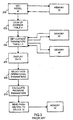
- FIG. 1 This prior art system 10 consists of a cardiac device 12 which may be, for example, a pacemaker, and a programmer 14.
- the programmer 14 may be used to program various cardiac stimulation devices, as discussed below.
- Device 12 consists of a hermetically sealed implantable housing 16. Attached to the device 12 may be one or two leads 18 and 20 which extend into the chambers of a heart 22.
- the device 12 includes electronic circuitry such as analog/digital interface circuit 24, a microprocessor 26, a telemetry module 28, a memory 30 and a power supply 32, all disposed in housing 16.
- Interface circuit 24 receives signals from leads 18, 20 which after processing go to microprocessor 26 over a bus 34 to the microprocessor 26. Information described below is exchanged between the microprocessor 26 and memory 30 over another bus 36. Power to all the circuits is provided by power supply 32.
- leads 18, 20 sense electrical activity in the chambers of the heart 22. This activity is processed and, if necessary, the microprocessor 26 generates digital pulses which are converted into analog pacing signals by interface circuit 24 and applied to the heart over leads 18, 20.
- a detailed description of this operation can be found in co-pending U.S. application S.N. 226,654 filed April 12, 1994, entitled FORCED ATRIOVENTRICULAR SYNCHRONY DUAL CHAMBER PACEMAKER, by T. A. Nappholz, which is incorporated herein by reference.
- the memory 30 is used to hold current programming parameters, as well as pacemaker specific information.
- the memory 30 may hold the serial number of the pacemaker, such as 0123111.
- the programmer 14 includes a microprocessor 40, an A/D interface 42, and a telemetry module 44.
- microprocessor 40 Associated with microprocessor 40 are a plurality of device memories 46, 48, 50, 52, 54 and a program memory 56.
- Memory 56 holds the program for the microprocessor 40. These memories are shown in separate physical blocks but can be implemented as in a large memory bank or as multiple replacement cartridges.
- the programmer can display instructions and various information on display 58, and commands for the microprocessor 40 can be entered on keyboard 60. Certain common subroutines are shared by the specific programming in memories 48-54 to save on memory space.
- the programmer 14 can be used for any one of a plurality of cardiac devices.
- Each memory 46-54 is dedicated to a particular cardiac device.
- memory bank 46 may be provided for device 12, and, accordingly, may hold the following listing.
- Table I contains information on specific product characteristics. TABLE I DESCRIPTION INFORMATION SERIAL NUMBERS 0001 - 10000; 20001 - 30,000 PACER MODEL META - DDDR 1254, 1256, 2258, 2260D... PACER STATUS IDE, R PHYSICAL INFORMATION SIZE, WEIGHT
- the Allowed Serial Numbers in the first row refers to a list of Serial Numbers that a device is allowed to have by the manufacturer. Each specific range of serial numbers is coupled to a Model Number identified in the second row.
- the third row identifies the status of the device, i.e. whether it is an experimental device (identified by the FDA as an Investigative Device Exemption, IDE) or a device commercially released (R).
- the third row contain physical information about each device, including size, weight, etc.
- memory 46 contains a second listing of other characteristics of the pacemaker 12, such as for example, various options, operational ranges and limits for various operational and programming parameters, and so on, as illustrated in Table II: TABLE II CHARACTERISTIC OPTIONS Modes AOO, VOO, DOO, VVIR, DDDR, DDIR Minimum Rate 50-120 in 5 ppm steps Maximum Rate 80-180 in 5 ppm steps Response Rate Factor 1-45 A-V Delay 0-200 in 20 ms steps Pacing Pulse Amplitude 2.5, 5, 7.5 V Electrodes Unipolar, Bipolar
- the first row of this table relates to the permissible modes of operation of the device 12.
- the second and third rows define the permissible minimum and maximum pacing rates, respectively, and also indicate the sizes of the steps for incrementing or decrementing these rates.
- the fourth, fifth, and sixth rows similarly pertain to permissible values for the response rate factor, A-V delay and pacing pulse amplitude, respectively.
- the seventh or last row indicates that the pacemaker can operate with either unipolar or bipolar leads.
- microprocessor 40 After communication is established between telemetry modules 28 and 44, in step 200 microprocessor 40 obtains the model number of the device 12. By convention, this information is always in a specific address of memory 30, such as 0000. Once the microprocessor 40 obtains this information, it checks to determine which of its memories 46-54 contains the information characteristic of the designated model. In the present case, the information pertaining to the model META DDDR 1254 is stored in memory 46. In step 202, the microprocessor 40 looks up the tables of device characteristics, programming parameters and options for the designated pacemaker. A partial listing of these tables are shown above as TABLE I and TABLE II.
- step 204 the various information designated by TABLE I is displayed.
- step 206 the information retrieved from the memory 30, as well as the information from Table II is shown on display 58.
- step 208 the physician selects the operational parameters he wants to change by entering commands on keyboard 60 for modifying the programming of device 12. As part of this step, the physician also selects different values for the parameters listed in Table I.
- step 210 the microprocessor re-calculates the new programming parameters necessary to conform to the instructions received in step 208.
- step 212 the new programming parameters are transmitted to the device 12 for storing in memory 30. The device 12 then can resume its operation using the new programming parameters.
- modifying the operation of device 12 in existing systems is a time consuming operation.
- the programmer 14 if it is to be used for initialzing or modifying the operation of various types of devices, it must contain in its memories various data specific to that device, such as the data shown in Tables I and II. If the programmer does not contain the necessary information, it must be updated.
- some patient specific historical data for long time periods for diagnostic purposes. For example it may be useful to record the patient's pacing threshold each time the patient visits his physician. At present, this type of data must be stored in the programmer, which means that the same programmer 14 must be used all the time for the same patient or access to previous programmed states in a print out. If the programmer is down during a patient visit, or the patient is at a different location, for example in an emergency, the historical data is unavailable.
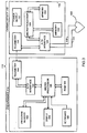
- System 110 constructed in accordance with the present invention is shown in Figure 3.
- System 110 includes a device 112 enclosed in a housing 116 and having a microprocessor 126, A/D interface 124, telemetry module 128, memory 130 and power supply 132 performing the same functions as the respective counterparts of Figure 1 except as noted below. These elements cooperate for sensing and pacing the chambers of heart 122 via leads 118 and 120.
- the system 110 includes a programmer 114 which can be used to program any one of a plurality of heart stimulating devices.
- the programmer 114 includes a microprocessor 140, A/D converter 142, telemetry module 144, program memory 156, display 158 and keyboard 160.
- the device 112 also includes a second memory 162.
- Memory 162 is used to store substantially all the information required to program the device 112, i.e., the information originally contained in memory 46 in the device 12 of Figure 1, and illustrated in Tables II and III. Of course, since Tables I and II are physically in the same location, i.e., within the device 112, they may be combined in a single table. In a preferred implementation memory 162 will be in ROM to ensure safety, minimum space and energy requirements. RAM is used only when absolutely unavoidable.
- the first row may contain the identification 'Model No.' and the actual model number of the device, i.e., 'META DDDR 3000' rather than an address location in memory 130.
- the entry in memory 162 may still be cross-referenced to an address in memory 130.
- Information stored in memory 162 can be optimized by storing it in a pre-arranged framework. This is best shown below: TABLE III LOCATION I.D.
- the 'LOCATION' is the sequential location normally maintained in the ROM. The programmer then vectors to LOCATION 1 in the implant which is always in one place and is given after the opening sequence of the telemetering the subsequent locations are in sequence and correspond to standard parameters. There is normally a correspondence between 'Location" and address. Location 'O' will normally be the identification of product. Preferably all the possible options are listed, as indicated below, for modes of operation with a "1" indicating that an option is available and a "0" indicating that the option is not available, as shown below. This corresponds to the 'MODE' code in Table III. For future options not yet developed, an industry accepted conversion may be used from existing options. TABLE IV AOO 0 AAI 1 VOO 0 VVI 1 VDI 1 DOO 1 DDI 0 DDD 0
- table III also contains at locations 20, 21 a listing of forbidden combinational states or operational parameters.
- a listing may be stored identifying the forbidden ranges for an operational parameter, such as the rate (location 21) for a specific mode of operation, such as AAI.
- This framework or data structure can be created to cover most of the options of implantable devices. Measurements and data logging can also use this approach as most of these items can be standardized. Correction factors and other pacing units can be handled in a similar manner. It is to be understood that a variety of structures are possible and the objective is to have flexibility at minimum cost of memory space.
- Table V below shows a typical memory 162 with the various information required to identify a specific implant. This information is readily changed for each model without any need for changing the programmer. The use of ROM for programmer specific information is not unreasonable imposition. In the case of some data in TABLE V the full ASCII CODE may be used, such as 'MODEL NAME' to give maximum flexibility. For most other information some simple framework will allow considerable saving of space and yet provide sufficient flexibility.
- the contents of the memory 162 may be extended to contain other information, such as a list of functions that can be monitored by the microprocessor 126. These functions then can be logged over time to generate historical data.
- the memory 162 may further include an indication of how much memory is available for storing the historical data.
- programmer 114 does not contain any specific information related to the device 112.
- the microprocessor 140 reads all the information from memory 162 required to program device 112. Patient specific information such as the patient's name, physician and so forth, are entered into the device 112 during an initialization phase.
- the received information is stored by the microprocessor 140 in a RAM (Random Access Memory) 164.
- step 304 information required by the physician for initializing or modifying the device 112 is displayed on display 158.
- the information can be displayed in the same format used by the present system (system 10) so that the physician need not learn any new skills for the operation of system 110.
- the physician selects the parameters that are to be modified in step 306, using the keyboard 160.
- the microprocessor 140 calculates the new programming parameters for the device 112.
- the new parameters are transmitted to the device 112.
- the device 112 receives the new parameters selected in step 306 or calculated in step 308.
- the microprocessor 126 stores the received information in memory 130 as required. The device 112 is now ready for operation.
- the programmer can also obtain from device 112 the information relevant for data logging.
- the physician may select the parameter to be logged as part of programming. These functions may include pulse threshold, ECG's, etc.
- the historical data stored in the memory 130 is retrieved and displayed by the programmer for analysis and diagnosis.
- the programmer 114 can be used with any number of cardiac stimulation devices without the need of a priori programming or updating regarding any particular device.
- the device 112 or any other heart stimulation device can be used with any other programmer without the loss of any information or flexibility of use.
- the cardiac device has been illustrated as having two separate memories, 130, 162.
- the device may be provided with a single memory performing the same function as memories 130, 162. Accordingly, the embodiment described in particular should be considered exemplary, not limiting, with respect to the following claims.
Landscapes
- Engineering & Computer Science (AREA)
- Health & Medical Sciences (AREA)
- Theoretical Computer Science (AREA)
- General Engineering & Computer Science (AREA)
- Software Systems (AREA)
- Public Health (AREA)
- Animal Behavior & Ethology (AREA)
- General Health & Medical Sciences (AREA)
- Life Sciences & Earth Sciences (AREA)
- Veterinary Medicine (AREA)
- Radiology & Medical Imaging (AREA)
- Nuclear Medicine, Radiotherapy & Molecular Imaging (AREA)
- Physics & Mathematics (AREA)
- General Physics & Mathematics (AREA)
- Biomedical Technology (AREA)
- Electrotherapy Devices (AREA)
- Measurement And Recording Of Electrical Phenomena And Electrical Characteristics Of The Living Body (AREA)
Abstract
A system for providing cardiac stimulation to a patient includes an implantable stimulation device with a microprocessor and a separate programmer. The stimulation device includes a memory holding substantially all the information necessary to program the device, including device specific information such as various modes of operations, the operational parameters associated with each mode, as well as patient specific information. All this information is transferred to the programmer for display and for generating a program. The program is than transferred back to the device for operating its microprocessor. In this manner, any programmer can be used to generate a program for any cardiac stimulation device without the need for providing specific programming information to the programmer for each specific device.
Description
- This invention pertains to a system for implantable cardiac stimulation, and more particularly to a system including an implantable cardiac stimulation device such as a pacemaker, defibrillator, cardioverter, and so on, which device includes a microprocessor for controlling the same, said system further including a universal, rather than a dedicated programmer, for programming the microprocessor. The present invention also pertains to a method of operating the improved system.
- Over the last couple of decades, significant improvements have been made in the field of implantable cardiac stimulation systems including devices such as pacemakers, defibrillators, cardioverters and combinations thereof. Typically, these devices consist of a housing holding the electronic circuitry and a power supply. The electronic circuitry is connected to the heart by one or more leads terminating in electrodes. The electronic circuitry consists of an interface to the leads, and a microprocessor for analyzing the signals from the leads and for generating the signals required for stimulating the heart, depending on the function of the device. Associated with the microprocessor is a memory used for storing programmable parameters used by the microprocessor for control. The system further includes an external device to provide the programming for the microprocessor. Communication between the pacemaker and the programmer takes place over a telemetry link.
- More specifically, the cardiac stimulation device includes a memory with several addresses, for holding device-specific information, such as identification and the current programming parameters. The device specific information uniquely identifies the implant by model and serial number. In order to check and modify the operation of the device, the programmer first accesses and retrieves from the device's memory its identification. The programmer than uses this information to call up from its own memory a complete set of addresses which then enable it to retrieve other specific operational characteristics of the device. This information is then displayed to the physician.
- The physician is then free to review the current parameters of the device on the programmer display, and modify them, if necessary. The programmer uses the modifications to generate a new program for the device. The new program is then transmitted to the implanted device. The term "program" is used generically to describe either the actual sequence of steps required to operate the implanted device, or a set of parameters which are required by the microprocessor within the device for its operation. These parameters may include, for example, a pacing mode, upper and lower pacing limits, a rate response factor, duration of various functions such as A-V delay or PVARP, and so on.
- In the existing cardiac stimulation systems, a dedicated programmer (i.e. separate software package) is provided for each type of cardiac stimulation device. Because of the lack of flexibility of the programmers, every time a device is modified, no matter how little the corresponding programmer software package has to be provided with a new set of characteristic functions associated with the modified devices.
- Therefore, it can be seen that, at present, a typical cardiac stimulator system is very inflexible in that modifications of the cardiac device must be accompanied by a corresponding modification of the programmer (usually software).
- Since the programmers are located either in hospitals or in the physicians' offices, upgrade of the programmers must be performed either by field personnel, who must receive special training for this task, or by a physician whose primary education is medicine, not electronics.
- A further disadvantage of the existing systems is that patient specific data including historical data is stored in the programmer, and therefore this historical data is useful only if the same programmer is used every time the patient visits his doctor for a check up or other procedure.
- In view of the above-mentioned disadvantages of the prior art, it is an objective of the present invention to provide an improved system wherein all (or part of) the information necessary for programming the implantable device, as well as the device-and patient-specific information is stored in the implantable device.
- A further objective is to provide a system having a universal programmer which can be used to handle any number of different cardiac devices without the need for modifying or updating its programming.
- A further objective is to provide a system wherein historic patient data may be stored on a long term basis in the implantable device.
- Other objectives and advantages of the invention shall become apparent from the following description. Briefly, a system constructed in accordance with this invention includes an implantable cardiac device and a programmer. The cardiac device includes cardiac stimulation means for applying a preselected cardiac therapy. The cardiac therapy could include pacing, antiarrhythmic therapy, defibrillation, or a combination thereof. The cardiac device also includes a controller, such as a microprocessor, for controlling the cardiac stimulation means and includes memory means for storing substantially all the information required for generating the program for the microprocessor. This information may include data descriptive of the operational characteristics of the device for operating the device in one of several modes, patient specific information and so on. In order to program the device, either for setting up a new cardiac therapy, or for modifying an existing cardiac therapy, communication is first established between the device and a separate programmer. The information from the memory means is then downloaded into the programmer. The programmer may display various information related to the device and the patient to assist the physician to decide what therapy to apply. The physician then enters instructions to the programmer for defining a new or modified therapy to be used. The programmer using these instructions and the information received from the device generates a new program. This new program is uploaded to the device together with new information for defining the same. At a later time, the device can be reprogrammed using a different general purpose programmer, since all the required information is found in the implanted device.
-
- Figure 1 shows a block diagram of a prior art cardiac stimulation system;
- Figure 2 shows a flow chart for the operation of the programmer of Figure 1;
- Figure 3 shows a block diagram of a system constructed in accordance with the present invention; and
- Figure 4 shows a flow chart for the system of Figure 3.
- For a complete and accurate understanding of the present invention, it is necessary first to describe a typical prior art system. One such system is shown in Figure 1. This
prior art system 10 consists of acardiac device 12 which may be, for example, a pacemaker, and aprogrammer 14. Theprogrammer 14 may be used to program various cardiac stimulation devices, as discussed below. -
Device 12 consists of a hermetically sealedimplantable housing 16. Attached to thedevice 12 may be one or two leads 18 and 20 which extend into the chambers of aheart 22. - The
device 12 includes electronic circuitry such as analog/digital interface circuit 24, amicroprocessor 26, atelemetry module 28, amemory 30 and apower supply 32, all disposed inhousing 16.Interface circuit 24 receives signals fromleads microprocessor 26 over abus 34 to themicroprocessor 26. Information described below is exchanged between themicroprocessor 26 andmemory 30 over anotherbus 36. Power to all the circuits is provided bypower supply 32. - In operation, leads 18, 20 sense electrical activity in the chambers of the
heart 22. This activity is processed and, if necessary, themicroprocessor 26 generates digital pulses which are converted into analog pacing signals byinterface circuit 24 and applied to the heart overleads - As mentioned above, the
memory 30 is used to hold current programming parameters, as well as pacemaker specific information. Typically, thememory 30 may hold the serial number of the pacemaker, such as 0123111. - As shown in Figure 1, the
programmer 14 includes amicroprocessor 40, an A/D interface 42, and atelemetry module 44. Associated withmicroprocessor 40 are a plurality ofdevice memories program memory 56.Memory 56 holds the program for themicroprocessor 40. These memories are shown in separate physical blocks but can be implemented as in a large memory bank or as multiple replacement cartridges. The programmer can display instructions and various information ondisplay 58, and commands for themicroprocessor 40 can be entered onkeyboard 60. Certain common subroutines are shared by the specific programming in memories 48-54 to save on memory space. - The
programmer 14 can be used for any one of a plurality of cardiac devices. Each memory 46-54 is dedicated to a particular cardiac device. For example,memory bank 46 may be provided fordevice 12, and, accordingly, may hold the following listing. Table I contains information on specific product characteristics.TABLE I DESCRIPTION INFORMATION SERIAL NUMBERS 0001 - 10000; 20001 - 30,000 PACER MODEL META - DDDR 1254, 1256, 2258, 2260D... PACER STATUS IDE, R PHYSICAL INFORMATION SIZE, WEIGHT - The Allowed Serial Numbers in the first row refers to a list of Serial Numbers that a device is allowed to have by the manufacturer. Each specific range of serial numbers is coupled to a Model Number identified in the second row. The third row identifies the status of the device, i.e. whether it is an experimental device (identified by the FDA as an Investigative Device Exemption, IDE) or a device commercially released (R). The third row contain physical information about each device, including size, weight, etc.
- In addition,
memory 46 contains a second listing of other characteristics of thepacemaker 12, such as for example, various options, operational ranges and limits for various operational and programming parameters, and so on, as illustrated in Table II:TABLE II CHARACTERISTIC OPTIONS Modes AOO, VOO, DOO, VVIR, DDDR, DDIR Minimum Rate 50-120 in 5 ppm steps Maximum Rate 80-180 in 5 ppm steps Response Rate Factor 1-45 A-V Delay 0-200 in 20 ms steps Pacing Pulse Amplitude 2.5, 5, 7.5 V Electrodes Unipolar, Bipolar - The first row of this table relates to the permissible modes of operation of the
device 12. The second and third rows define the permissible minimum and maximum pacing rates, respectively, and also indicate the sizes of the steps for incrementing or decrementing these rates. The fourth, fifth, and sixth rows similarly pertain to permissible values for the response rate factor, A-V delay and pacing pulse amplitude, respectively. The seventh or last row indicates that the pacemaker can operate with either unipolar or bipolar leads. - The programming of
device 12 is modified as illustrated in the flow chart of Figure 2. After communication is established betweentelemetry modules step 200microprocessor 40 obtains the model number of thedevice 12. By convention, this information is always in a specific address ofmemory 30, such as 0000. Once themicroprocessor 40 obtains this information, it checks to determine which of its memories 46-54 contains the information characteristic of the designated model. In the present case, the information pertaining to the model META DDDR 1254 is stored inmemory 46. Instep 202, themicroprocessor 40 looks up the tables of device characteristics, programming parameters and options for the designated pacemaker. A partial listing of these tables are shown above as TABLE I and TABLE II. - Back to the flow chart of Figure 2, in
step 204, the various information designated by TABLE I is displayed. Instep 206 the information retrieved from thememory 30, as well as the information from Table II is shown ondisplay 58. Instep 208, the physician selects the operational parameters he wants to change by entering commands onkeyboard 60 for modifying the programming ofdevice 12. As part of this step, the physician also selects different values for the parameters listed in Table I. Instep 210, the microprocessor re-calculates the new programming parameters necessary to conform to the instructions received instep 208. In step 212 the new programming parameters are transmitted to thedevice 12 for storing inmemory 30. Thedevice 12 then can resume its operation using the new programming parameters. - As can be seen from the above description, modifying the operation of
device 12 in existing systems is a time consuming operation. Moreover, if theprogrammer 14 is to be used for initialzing or modifying the operation of various types of devices, it must contain in its memories various data specific to that device, such as the data shown in Tables I and II. If the programmer does not contain the necessary information, it must be updated. - In certain instances, it is desirable to store some patient specific historical data for long time periods for diagnostic purposes. For example it may be useful to record the patient's pacing threshold each time the patient visits his physician. At present, this type of data must be stored in the programmer, which means that the
same programmer 14 must be used all the time for the same patient or access to previous programmed states in a print out. If the programmer is down during a patient visit, or the patient is at a different location, for example in an emergency, the historical data is unavailable. - A
system 110 constructed in accordance with the present invention is shown in Figure 3. For this Figure, the elements similar to the ones in Figure 1 are identified by the same numerals preceded by a '1'.System 110 includes adevice 112 enclosed in ahousing 116 and having amicroprocessor 126, A/D interface 124,telemetry module 128,memory 130 andpower supply 132 performing the same functions as the respective counterparts of Figure 1 except as noted below. These elements cooperate for sensing and pacing the chambers ofheart 122 vialeads - As in Figure 1, the
system 110 includes aprogrammer 114 which can be used to program any one of a plurality of heart stimulating devices. Theprogrammer 114 includes amicroprocessor 140, A/D converter 142,telemetry module 144,program memory 156,display 158 andkeyboard 160. - An important difference between the
systems system 110, thedevice 112 also includes asecond memory 162.Memory 162 is used to store substantially all the information required to program thedevice 112, i.e., the information originally contained inmemory 46 in thedevice 12 of Figure 1, and illustrated in Tables II and III. Of course, since Tables I and II are physically in the same location, i.e., within thedevice 112, they may be combined in a single table. In apreferred implementation memory 162 will be in ROM to ensure safety, minimum space and energy requirements. RAM is used only when absolutely unavoidable. For example, the first row may contain the identification 'Model No.' and the actual model number of the device, i.e., 'META DDDR 3000' rather than an address location inmemory 130. Of course, for some parameters being used by themicroprocessor 112 during its actual operation, the entry inmemory 162 may still be cross-referenced to an address inmemory 130. Information stored inmemory 162 can be optimized by storing it in a pre-arranged framework. This is best shown below:TABLE III LOCATION I.D. OPTIONS START ADDRESS 11 MODE 1010111 00000001 12 RATE 010111 00000010 13 A_PW 111110 00000011 14 A_AMPL 011110 00000100 LOCATION FORBIDDEN STATES 20 11 00000010 010100 21 12 00010000 010101 - The 'LOCATION' is the sequential location normally maintained in the ROM. The programmer then vectors to LOCATION 1 in the implant which is always in one place and is given after the opening sequence of the telemetering the subsequent locations are in sequence and correspond to standard parameters. There is normally a correspondence between 'Location" and address. Location 'O' will normally be the identification of product. Preferably all the possible options are listed, as indicated below, for modes of operation with a "1" indicating that an option is available and a "0" indicating that the option is not available, as shown below. This corresponds to the 'MODE' code in Table III. For future options not yet developed, an industry accepted conversion may be used from existing options.
TABLE IV AOO 0 AAI 1 VOO 0 VVI 1 VDI 1 DOO 1 DDI 0 DDD 0 - In addition, table III also contains at
locations 20, 21 a listing of forbidden combinational states or operational parameters. For example, atlocations 20 and 21, a listing may be stored identifying the forbidden ranges for an operational parameter, such as the rate (location 21) for a specific mode of operation, such as AAI. - This framework or data structure can be created to cover most of the options of implantable devices. Measurements and data logging can also use this approach as most of these items can be standardized. Correction factors and other pacing units can be handled in a similar manner. It is to be understood that a variety of structures are possible and the objective is to have flexibility at minimum cost of memory space.
- Table V below shows a
typical memory 162 with the various information required to identify a specific implant. This information is readily changed for each model without any need for changing the programmer. The use of ROM for programmer specific information is not unreasonable imposition. In the case of some data in TABLE V the full ASCII CODE may be used, such as 'MODEL NAME' to give maximum flexibility. For most other information some simple framework will allow considerable saving of space and yet provide sufficient flexibility.TABLE V LOCATION I.D. INFO 0 MODEL META-ATM 1 SERIAL NO. 0123111 2 CONFIGURATION BIPOLAR, SSI 3 LEADS VS 1 4 VOLUME 30 CC 5 DIMENSION 6 X 45 X 51 6 WEIGHT 25 - Importantly, the contents of the
memory 162 may be extended to contain other information, such as a list of functions that can be monitored by themicroprocessor 126. These functions then can be logged over time to generate historical data. Thememory 162 may further include an indication of how much memory is available for storing the historical data. - The operation of
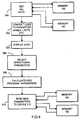
system 110 is shown in Figure 4. Initially,programmer 114 does not contain any specific information related to thedevice 112. After communication is established between theprogrammer 114 anddevice 112 bytelemetry modules step 300 themicroprocessor 140 reads all the information frommemory 162 required to programdevice 112. Patient specific information such as the patient's name, physician and so forth, are entered into thedevice 112 during an initialization phase. Instep 302 the received information is stored by themicroprocessor 140 in a RAM (Random Access Memory) 164. Instep 304 information required by the physician for initializing or modifying thedevice 112 is displayed ondisplay 158. Importantly, the information can be displayed in the same format used by the present system (system 10) so that the physician need not learn any new skills for the operation ofsystem 110. The physician selects the parameters that are to be modified instep 306, using thekeyboard 160. Instep 308 themicroprocessor 140 calculates the new programming parameters for thedevice 112. Instep 310 the new parameters are transmitted to thedevice 112. Thedevice 112 receives the new parameters selected instep 306 or calculated instep 308. Themicroprocessor 126 stores the received information inmemory 130 as required. Thedevice 112 is now ready for operation. - If required, the programmer can also obtain from
device 112 the information relevant for data logging. The physician may select the parameter to be logged as part of programming. These functions may include pulse threshold, ECG's, etc. - During the following visit, the historical data stored in the
memory 130 is retrieved and displayed by the programmer for analysis and diagnosis. - Importantly, the
programmer 114 can be used with any number of cardiac stimulation devices without the need of a priori programming or updating regarding any particular device. Similarly, thedevice 112 or any other heart stimulation device can be used with any other programmer without the loss of any information or flexibility of use. - Although the invention has been described with reference to a particular embodiment, it is to be understood that this embodiment is merely illustrative of the application of the principles of the invention. For example, the cardiac device has been illustrated as having two separate memories, 130, 162. However, the device may be provided with a single memory performing the same function as
memories
Claims (18)
- A cardiac stimulation system comprising:a cardiac stimulation device having an implantable housing, said housing including (a) stimulation sensing means, (b) microprocessor means for controlling said stimulation sensing means, (c) memory means for storing substantially all the information required for generating a program for operating said microprocessor means; and (d)internal communication means; anda device programmer remote from said device, said programmer including a programmer communication means for communication with said internal communication means, said device programmer being constructed and arranged for retrieving said information from said memory means, generating said program based on said information and transmitting said program to said device for storage.
- The system of claim 1 wherein said programmer includes display means for displaying said information.
- The system of claim 1 wherein said programmer further includes data entry means for entering data.
- The system of claim 1 wherein said information includes pacemaker specific data.
- The system of claim 1 wherein said housing is implanted in a patient and wherein said information includes patient specific data.
- The system of claim 1 wherein said device is operable in one of a plurality of modes of operation, each mode of operation being defined by a plurality of parameters, wherein said information includes said parameters.
- A cardiac stimulation device comprising:an implantable housing;stimulation means disposed in said housing for selectively applying cardiac stimulation to a patient when said housing is implanted in said patient;control means disposed in said housing for controlling said stimulation means in accordance with a program; andmemory means disposed in said housing for storing substantially all the information required to generate said program.
- The device of claim 7 wherein said memory means includes device specific information.
- The device of claim 7 wherein said memory means includes patient specific information.
- The device of claim 7 wherein stimulation means includes several modes of operation, each mode being defined by a corresponding set of parameters, wherein said parameters are stored in said memory means.
- The device of claim 7 wherein said memory means further includes historical data specific to said patient.
- The device of claim 7 further comprising a communication member for communicating said information to an external programmer.
- A method of programming a cardiac stimulation device, said device having a memory holding substantially all the information required to program said device, comprising the steps of:providing a programmer physically separate from said device;transferring all said information from said memory to said programmer;generating with said programmer a program for said device; andtransferring said program to said device.
- The method of claim 13 wherein said program is added on a set of parameters, wherein said parameters are transferred to said device with said program.
- The method of claim 13 wherein said information includes patient specific information.
- The method of claim 15 wherein said patient specific information is displayed on a display during said programming step.
- The method of claim 13 wherein said program is generated by selecting a device function for monitoring over an extended time period.
- The method of claim 17 wherein said function is logged in said memory.
Applications Claiming Priority (2)
| Application Number | Priority Date | Filing Date | Title |
|---|---|---|---|
| US40163995A | 1995-03-08 | 1995-03-08 | |
| US401639 | 1995-03-08 |
Publications (2)
| Publication Number | Publication Date |
|---|---|
| EP0730882A2 true EP0730882A2 (en) | 1996-09-11 |
| EP0730882A3 EP0730882A3 (en) | 1997-08-06 |
Family
ID=23588600
Family Applications (1)
| Application Number | Title | Priority Date | Filing Date |
|---|---|---|---|
| EP96301418A Withdrawn EP0730882A3 (en) | 1995-03-08 | 1996-03-01 | An improved implantable cardiac stimulation system |
Country Status (2)
| Country | Link |
|---|---|
| US (1) | US5690690A (en) |
| EP (1) | EP0730882A3 (en) |
Cited By (22)
| Publication number | Priority date | Publication date | Assignee | Title |
|---|---|---|---|---|
| EP0756877A2 (en) * | 1995-08-02 | 1997-02-05 | Pacesetter, Inc. | Decision support system and method for an implantable cardiac stimulating device |
| WO1997026043A1 (en) * | 1996-01-16 | 1997-07-24 | Medtronic, Inc. | Compressed patient narrative storage in and full text reconstruction from implantable medical devices |
| WO1997043004A1 (en) * | 1996-05-16 | 1997-11-20 | Sulzer Intermedics Inc. | Programmably upgradable implantable medical device |
| US5800473A (en) * | 1996-02-08 | 1998-09-01 | Ela Medical S.A. | Systems, methods, and apparatus for automatic updating of a programmer for an active implantable medical device |
| EP0890370A1 (en) * | 1997-07-09 | 1999-01-13 | Vitatron Medical B.V. | Pacemaker system with enhanced programmable modification capacity |
| WO1999010043A1 (en) * | 1997-08-29 | 1999-03-04 | Medtronic, Inc. | Cardiac pacing with multiple pacing therapy features |
| EP0917079A2 (en) * | 1997-11-07 | 1999-05-19 | Orga Kartensysteme GmbH | Data processing unit and method for data processing |
| FR2800489A1 (en) * | 1999-10-29 | 2001-05-04 | Medtronic Inc | SYSTEMS AND METHODS FOR INVOICING OR INVENTORING MEDICAL DEVICE SYSTEMS |
| WO2003003956A1 (en) * | 2001-07-06 | 2003-01-16 | Cochlear Limited | Configuration of implanted devices |
| WO2004093990A1 (en) * | 2003-04-02 | 2004-11-04 | Medtronic, Inc. | Management of neurostimulation therapy using a plurality of stored parameter sets |
| US7463928B2 (en) | 2003-04-25 | 2008-12-09 | Medtronic, Inc. | Identifying combinations of electrodes for neurostimulation therapy |
| US7505815B2 (en) | 2003-04-02 | 2009-03-17 | Medtronic, Inc. | Neurostimulation therapy usage diagnostics |
| US7548786B2 (en) | 2003-04-02 | 2009-06-16 | Medtronic, Inc. | Library for management of neurostimulation therapy programs |
| US7774067B2 (en) | 2006-04-12 | 2010-08-10 | Medtronic, Inc. | Autogeneration of neurostimulation therapy program groups |
| US7819909B2 (en) | 2004-07-20 | 2010-10-26 | Medtronic, Inc. | Therapy programming guidance based on stored programming history |
| US7894908B2 (en) | 2003-04-02 | 2011-02-22 | Medtronic, Inc. | Neurostimulation therapy optimization based on a rated session log |
| US8630715B2 (en) | 2006-04-12 | 2014-01-14 | Medtronic, Inc. | Rule-based stimulation program search |
| US8694115B2 (en) | 2004-07-20 | 2014-04-08 | Medtronic, Inc. | Therapy programming guidance based on stored programming history |
| US8784312B2 (en) | 2006-02-10 | 2014-07-22 | Cochlear Limited | Recognition of implantable medical device |
| US10105539B2 (en) | 2014-12-17 | 2018-10-23 | Cochlear Limited | Configuring a stimulation unit of a hearing device |
| US10576275B2 (en) | 2001-07-06 | 2020-03-03 | Cochlear Limited | System and method for configuring an external device using operating parameters from an implanted device |
| US10602284B2 (en) | 2016-07-18 | 2020-03-24 | Cochlear Limited | Transducer management |
Families Citing this family (51)
| Publication number | Priority date | Publication date | Assignee | Title |
|---|---|---|---|---|
| US6968375B1 (en) * | 1997-03-28 | 2005-11-22 | Health Hero Network, Inc. | Networked system for interactive communication and remote monitoring of individuals |
| US5307263A (en) | 1992-11-17 | 1994-04-26 | Raya Systems, Inc. | Modular microprocessor-based health monitoring system |
| WO2001037174A1 (en) | 1992-11-17 | 2001-05-25 | Health Hero Network, Inc. | Method and system for improving adherence with a diet program or other medical regimen |
| US20010011224A1 (en) | 1995-06-07 | 2001-08-02 | Stephen James Brown | Modular microprocessor-based health monitoring system |
| US9215979B2 (en) * | 1992-11-17 | 2015-12-22 | Robert Bosch Healthcare Systems, Inc. | Multi-user remote health monitoring system |
| US7624028B1 (en) | 1992-11-17 | 2009-11-24 | Health Hero Network, Inc. | Remote health monitoring and maintenance system |
| US5873733A (en) * | 1998-01-23 | 1999-02-23 | Sulzer Intermedics Inc. | Training unit for the pacemaker emergency intervention system using magnetic entry code |
| US6243608B1 (en) | 1998-06-12 | 2001-06-05 | Intermedics Inc. | Implantable device with optical telemetry |
| US6088618A (en) * | 1998-07-07 | 2000-07-11 | Vitatron Medical, B.V. | Pacemaker system and method for providing manual display concurrent with pacemaker software modification |
| US6308099B1 (en) | 1998-11-13 | 2001-10-23 | Intermedics Inc. | Implantable device and programmer system which permits multiple programmers |
| US6285909B1 (en) * | 1999-05-27 | 2001-09-04 | Cardiac Pacemakers, Inc. | Preserving patient specific data in implantable pulse generator systems |
| US7181505B2 (en) * | 1999-07-07 | 2007-02-20 | Medtronic, Inc. | System and method for remote programming of an implantable medical device |
| US6497655B1 (en) * | 1999-12-17 | 2002-12-24 | Medtronic, Inc. | Virtual remote monitor, alert, diagnostics and programming for implantable medical device systems |
| US6650944B2 (en) * | 2000-02-23 | 2003-11-18 | Medtronic, Inc. | Follow-up monitoring method and system for implantable medical devices |
| US6622040B2 (en) | 2000-12-15 | 2003-09-16 | Cardiac Pacemakers, Inc. | Automatic selection of stimulation chamber for ventricular resynchronization therapy |
| US7181285B2 (en) * | 2000-12-26 | 2007-02-20 | Cardiac Pacemakers, Inc. | Expert system and method |
| AUPR247601A0 (en) * | 2001-01-10 | 2001-02-01 | Cochlear Limited | Cochlear implant communicator |
| US6622045B2 (en) * | 2001-03-29 | 2003-09-16 | Pacesetter, Inc. | System and method for remote programming of implantable cardiac stimulation devices |
| AUPR551301A0 (en) * | 2001-06-06 | 2001-07-12 | Cochlear Limited | Monitor for auditory prosthesis |
| US6766198B1 (en) * | 2001-08-09 | 2004-07-20 | Pacesetter, Inc. | System and method for providing patient status information during interrogation of an implantable cardiac stimulation device |
| SE0102918D0 (en) * | 2001-08-30 | 2001-08-30 | St Jude Medical | Method of providing software to an implantable medical device system |
| US7383088B2 (en) | 2001-11-07 | 2008-06-03 | Cardiac Pacemakers, Inc. | Centralized management system for programmable medical devices |
| US20040122294A1 (en) | 2002-12-18 | 2004-06-24 | John Hatlestad | Advanced patient management with environmental data |
| US7043305B2 (en) | 2002-03-06 | 2006-05-09 | Cardiac Pacemakers, Inc. | Method and apparatus for establishing context among events and optimizing implanted medical device performance |
| US7468032B2 (en) | 2002-12-18 | 2008-12-23 | Cardiac Pacemakers, Inc. | Advanced patient management for identifying, displaying and assisting with correlating health-related data |
| US8043213B2 (en) | 2002-12-18 | 2011-10-25 | Cardiac Pacemakers, Inc. | Advanced patient management for triaging health-related data using color codes |
| US7983759B2 (en) | 2002-12-18 | 2011-07-19 | Cardiac Pacemakers, Inc. | Advanced patient management for reporting multiple health-related parameters |
| US8391989B2 (en) | 2002-12-18 | 2013-03-05 | Cardiac Pacemakers, Inc. | Advanced patient management for defining, identifying and using predetermined health-related events |
| US20040122487A1 (en) | 2002-12-18 | 2004-06-24 | John Hatlestad | Advanced patient management with composite parameter indices |
| US7113825B2 (en) | 2002-05-03 | 2006-09-26 | Cardiac Pacemakers, Inc. | Method and apparatus for detecting acoustic oscillations in cardiac rhythm |
| US7373206B2 (en) * | 2002-10-31 | 2008-05-13 | Medtronic, Inc. | Failsafe programming of implantable medical devices |
| US7972275B2 (en) | 2002-12-30 | 2011-07-05 | Cardiac Pacemakers, Inc. | Method and apparatus for monitoring of diastolic hemodynamics |
| US7136707B2 (en) * | 2003-01-21 | 2006-11-14 | Cardiac Pacemakers, Inc. | Recordable macros for pacemaker follow-up |
| US7742821B1 (en) | 2003-06-11 | 2010-06-22 | Boston Scientific Neutomodulation Corporation | Remote control for implantable medical device |
| US20040215278A1 (en) * | 2003-04-25 | 2004-10-28 | Wim Stegink | Method and apparatus for locally upgrading implanted reprogrammable medical devices |
| US20040230456A1 (en) * | 2003-05-14 | 2004-11-18 | Lozier Luke R. | System for identifying candidates for ICD implantation |
| US7539803B2 (en) * | 2003-06-13 | 2009-05-26 | Agere Systems Inc. | Bi-directional interface for low data rate application |
| US20050137641A1 (en) * | 2003-12-08 | 2005-06-23 | Alexandra Naughton | User interface for cardiac rhythm management device programmer |
| US8359338B2 (en) * | 2004-07-30 | 2013-01-22 | Carefusion 303, Inc. | System and method for managing medical databases for patient care devices |
| US8285378B1 (en) * | 2004-09-27 | 2012-10-09 | Cardiac Pacemakers, Inc | System and method for determining patient-specific implantable medical device programming parameters |
| US7257447B2 (en) | 2005-04-20 | 2007-08-14 | Cardiac Pacemakers, Inc. | Method and apparatus for indication-based programming of cardiac rhythm management devices |
| US8108034B2 (en) | 2005-11-28 | 2012-01-31 | Cardiac Pacemakers, Inc. | Systems and methods for valvular regurgitation detection |
| US20070185545A1 (en) * | 2006-02-06 | 2007-08-09 | Medtronic Emergency Response Systems, Inc. | Post-download patient data protection in a medical device |
| US8666488B2 (en) | 2006-02-06 | 2014-03-04 | Physio-Control, Inc. | Post-download patient data protection in a medical device |
| WO2008069897A2 (en) * | 2006-12-06 | 2008-06-12 | Medtronic, Inc. | Medical device programming safety |
| US9007478B2 (en) * | 2007-01-09 | 2015-04-14 | Capso Vision, Inc. | Methods to compensate manufacturing variations and design imperfections in a capsule camera |
| US20100057167A1 (en) * | 2008-09-02 | 2010-03-04 | Xander Evers | System and Method for the Interrogation of Implantable Medical Devices |
| US8600504B2 (en) | 2010-07-02 | 2013-12-03 | Cardiac Pacemakers, Inc. | Physiologic demand driven pacing |
| WO2012112178A1 (en) | 2011-02-18 | 2012-08-23 | Medtronic,Inc | Modular medical device programmer |
| CN103370099B (en) | 2011-02-18 | 2016-01-13 | 美敦力公司 | There is the medical treatment device programmable device of adjustable support |
| US11134902B2 (en) | 2017-12-26 | 2021-10-05 | Cardiac Pacemakers, Inc. | Identification of implanted electrode location |
Citations (2)
| Publication number | Priority date | Publication date | Assignee | Title |
|---|---|---|---|---|
| WO1995013112A1 (en) * | 1993-11-12 | 1995-05-18 | Pacesetter, Inc. | Programming system having multiple program modules |
| US5456692A (en) * | 1993-09-03 | 1995-10-10 | Pacesetter, Inc. | System and method for noninvasively altering the function of an implanted pacemaker |
Family Cites Families (5)
| Publication number | Priority date | Publication date | Assignee | Title |
|---|---|---|---|---|
| US4958632A (en) * | 1978-07-20 | 1990-09-25 | Medtronic, Inc. | Adaptable, digital computer controlled cardiac pacemaker |
| US4726380A (en) * | 1983-10-17 | 1988-02-23 | Telectronics, N.V. | Implantable cardiac pacer with discontinuous microprocessor, programmable antitachycardia mechanisms and patient data telemetry |
| DE3688577D1 (en) * | 1985-09-17 | 1993-07-22 | Biotronik Mess & Therapieg | HEART PACEMAKER. |
| US5080096A (en) * | 1990-07-06 | 1992-01-14 | Medtronic, Inc. | Method and apparatus for accessing a nonvolatile memory |
| US5330513A (en) * | 1992-05-01 | 1994-07-19 | Medtronic, Inc. | Diagnostic function data storage and telemetry out for rate responsive cardiac pacemaker |
-
1996
- 1996-03-01 EP EP96301418A patent/EP0730882A3/en not_active Withdrawn
- 1996-09-12 US US08/712,238 patent/US5690690A/en not_active Expired - Lifetime
Patent Citations (2)
| Publication number | Priority date | Publication date | Assignee | Title |
|---|---|---|---|---|
| US5456692A (en) * | 1993-09-03 | 1995-10-10 | Pacesetter, Inc. | System and method for noninvasively altering the function of an implanted pacemaker |
| WO1995013112A1 (en) * | 1993-11-12 | 1995-05-18 | Pacesetter, Inc. | Programming system having multiple program modules |
Non-Patent Citations (1)
| Title |
|---|
| COMPUTERS IN CARDIOLOGY, September 1991, VENICE,ITALY, pages 149-152, XP000309358 M.MALIK,C.EKWALL: "Personal Computed Based Software Operated Dual Chamber Stimulator" * |
Cited By (41)
| Publication number | Priority date | Publication date | Assignee | Title |
|---|---|---|---|---|
| EP0756877A2 (en) * | 1995-08-02 | 1997-02-05 | Pacesetter, Inc. | Decision support system and method for an implantable cardiac stimulating device |
| EP0756877A3 (en) * | 1995-08-02 | 1998-06-03 | Pacesetter, Inc. | Decision support system and method for an implantable cardiac stimulating device |
| WO1997026043A1 (en) * | 1996-01-16 | 1997-07-24 | Medtronic, Inc. | Compressed patient narrative storage in and full text reconstruction from implantable medical devices |
| US5800473A (en) * | 1996-02-08 | 1998-09-01 | Ela Medical S.A. | Systems, methods, and apparatus for automatic updating of a programmer for an active implantable medical device |
| US6073049A (en) * | 1996-05-16 | 2000-06-06 | Sulzer Intermedics, Inc. | Programmably upgradable implantable cardiac pacemaker |
| WO1997043004A1 (en) * | 1996-05-16 | 1997-11-20 | Sulzer Intermedics Inc. | Programmably upgradable implantable medical device |
| EP0890370A1 (en) * | 1997-07-09 | 1999-01-13 | Vitatron Medical B.V. | Pacemaker system with enhanced programmable modification capacity |
| WO1999010043A1 (en) * | 1997-08-29 | 1999-03-04 | Medtronic, Inc. | Cardiac pacing with multiple pacing therapy features |
| EP0917079A2 (en) * | 1997-11-07 | 1999-05-19 | Orga Kartensysteme GmbH | Data processing unit and method for data processing |
| EP0917079A3 (en) * | 1997-11-07 | 2002-01-23 | Orga Kartensysteme GmbH | Data processing unit and method for data processing |
| FR2800489A1 (en) * | 1999-10-29 | 2001-05-04 | Medtronic Inc | SYSTEMS AND METHODS FOR INVOICING OR INVENTORING MEDICAL DEVICE SYSTEMS |
| WO2003003956A1 (en) * | 2001-07-06 | 2003-01-16 | Cochlear Limited | Configuration of implanted devices |
| EP1411876A1 (en) * | 2001-07-06 | 2004-04-28 | Cochlear Limited | Configuration of implanted devices |
| US10981012B2 (en) | 2001-07-06 | 2021-04-20 | Cochlear Limited | Configuration of implanted devices |
| EP1411876A4 (en) * | 2001-07-06 | 2005-06-01 | Cochlear Ltd | Configuration of implanted devices |
| AU2001272189B2 (en) * | 2001-07-06 | 2008-10-09 | Cochlear Limited | Configuration of implanted devices |
| US10576275B2 (en) | 2001-07-06 | 2020-03-03 | Cochlear Limited | System and method for configuring an external device using operating parameters from an implanted device |
| US7502653B2 (en) | 2001-07-06 | 2009-03-10 | Cochlear Limited | Cochlear implant having patient-specific parameter storage |
| US7548786B2 (en) | 2003-04-02 | 2009-06-16 | Medtronic, Inc. | Library for management of neurostimulation therapy programs |
| US8095220B2 (en) | 2003-04-02 | 2012-01-10 | Medtronic, Inc. | Neurostimulation therapy usage diagnostics |
| US7489970B2 (en) | 2003-04-02 | 2009-02-10 | Medtronic, Inc. | Management of neurostimulation therapy using parameter sets |
| WO2004093990A1 (en) * | 2003-04-02 | 2004-11-04 | Medtronic, Inc. | Management of neurostimulation therapy using a plurality of stored parameter sets |
| US8843203B2 (en) | 2003-04-02 | 2014-09-23 | Medtronic, Inc. | Neurostimulation therapy usage diagnostics |
| US7505815B2 (en) | 2003-04-02 | 2009-03-17 | Medtronic, Inc. | Neurostimulation therapy usage diagnostics |
| US7894908B2 (en) | 2003-04-02 | 2011-02-22 | Medtronic, Inc. | Neurostimulation therapy optimization based on a rated session log |
| US8155749B2 (en) | 2003-04-02 | 2012-04-10 | Medtronic, Inc. | Management of neurostimulation therapy using parameter sets |
| US8649872B2 (en) | 2003-04-25 | 2014-02-11 | Medtronic, Inc. | Identifying combinations of electrodes for neurostimulation therapy |
| US9186517B2 (en) | 2003-04-25 | 2015-11-17 | Medtronic, Inc. | Identifying combinations of electrodes for neurostimulation therapy |
| US7463928B2 (en) | 2003-04-25 | 2008-12-09 | Medtronic, Inc. | Identifying combinations of electrodes for neurostimulation therapy |
| US7826901B2 (en) | 2003-04-25 | 2010-11-02 | Medtronic, Inc. | Generation of therapy programs and program groups |
| US8068915B2 (en) | 2003-04-25 | 2011-11-29 | Medtronic, Inc. | Generation of therapy programs and program groups |
| US8694115B2 (en) | 2004-07-20 | 2014-04-08 | Medtronic, Inc. | Therapy programming guidance based on stored programming history |
| US7819909B2 (en) | 2004-07-20 | 2010-10-26 | Medtronic, Inc. | Therapy programming guidance based on stored programming history |
| US8784312B2 (en) | 2006-02-10 | 2014-07-22 | Cochlear Limited | Recognition of implantable medical device |
| USRE48038E1 (en) | 2006-02-10 | 2020-06-09 | Cochlear Limited | Recognition of implantable medical device |
| USRE49527E1 (en) | 2006-02-10 | 2023-05-16 | Cochlear Limited | Recognition of implantable medical device |
| US8712539B2 (en) | 2006-04-12 | 2014-04-29 | Medtronic, Inc. | Rule-based stimulation program search |
| US8630715B2 (en) | 2006-04-12 | 2014-01-14 | Medtronic, Inc. | Rule-based stimulation program search |
| US7774067B2 (en) | 2006-04-12 | 2010-08-10 | Medtronic, Inc. | Autogeneration of neurostimulation therapy program groups |
| US10105539B2 (en) | 2014-12-17 | 2018-10-23 | Cochlear Limited | Configuring a stimulation unit of a hearing device |
| US10602284B2 (en) | 2016-07-18 | 2020-03-24 | Cochlear Limited | Transducer management |
Also Published As
| Publication number | Publication date |
|---|---|
| US5690690A (en) | 1997-11-25 |
| EP0730882A3 (en) | 1997-08-06 |
Similar Documents
| Publication | Publication Date | Title |
|---|---|---|
| US5690690A (en) | Implantable cardiac stimulation system | |
| US8321366B2 (en) | Systems and methods for automatically resolving interaction between programmable parameters | |
| EP0970722B1 (en) | Programmer system for implanted medical devices | |
| JP5054001B2 (en) | Cardiac rhythm management with an implantable cardioverter defibrillator with programmable capacitor charge level, an external system for communicating with the implantable cardioverter defibrillator, and an implantable cardioverter defibrillator system | |
| EP0890370B1 (en) | Pacemaker system with enhanced programmable modification capacity | |
| US5456692A (en) | System and method for noninvasively altering the function of an implanted pacemaker | |
| EP1009479B1 (en) | Cardiac pacing with multiple pacing therapy features | |
| US6622045B2 (en) | System and method for remote programming of implantable cardiac stimulation devices | |
| US8352038B2 (en) | Medical device function configuration post-manufacturing | |
| US5456691A (en) | Programming system having multiple program modules | |
| US4867161A (en) | Cardiac pacemaker | |
| US20080077031A1 (en) | System and method for remote expert-system medical device programming | |
| US20050192640A1 (en) | Method and apparatus for implementing task-oriented induction capabilities in an implantable cardioverter defibrillator and programmer | |
| US6766198B1 (en) | System and method for providing patient status information during interrogation of an implantable cardiac stimulation device | |
| US6735478B1 (en) | System and method for providing patient status information during interrogation of an implantable cardiac stimulation device | |
| EP1987858B1 (en) | Follow-up support system for implantable medical devices | |
| US8812110B2 (en) | Implantable medical device |
Legal Events
| Date | Code | Title | Description |
|---|---|---|---|
| PUAI | Public reference made under article 153(3) epc to a published international application that has entered the european phase |
Free format text: ORIGINAL CODE: 0009012 |
|
| AK | Designated contracting states |
Kind code of ref document: A2 Designated state(s): DE FR GB |
|
| PUAL | Search report despatched |
Free format text: ORIGINAL CODE: 0009013 |
|
| AK | Designated contracting states |
Kind code of ref document: A3 Designated state(s): DE FR GB |
|
| 17P | Request for examination filed |
Effective date: 19970828 |
|
| STAA | Information on the status of an ep patent application or granted ep patent |
Free format text: STATUS: THE APPLICATION HAS BEEN WITHDRAWN |
|
| 18W | Application withdrawn |
Withdrawal date: 19990115 |