EP0706286A2 - Color printer calibration correcting for local printer non-linearities - Google Patents
Color printer calibration correcting for local printer non-linearities Download PDFInfo
- Publication number
- EP0706286A2 EP0706286A2 EP95307011A EP95307011A EP0706286A2 EP 0706286 A2 EP0706286 A2 EP 0706286A2 EP 95307011 A EP95307011 A EP 95307011A EP 95307011 A EP95307011 A EP 95307011A EP 0706286 A2 EP0706286 A2 EP 0706286A2
- Authority
- EP
- European Patent Office
- Prior art keywords
- color
- mappings
- mapping
- expanded
- color mapping
- Prior art date
- Legal status (The legal status is an assumption and is not a legal conclusion. Google has not performed a legal analysis and makes no representation as to the accuracy of the status listed.)
- Granted
Links
Images


Classifications
-
- H—ELECTRICITY
- H04—ELECTRIC COMMUNICATION TECHNIQUE
- H04N—PICTORIAL COMMUNICATION, e.g. TELEVISION
- H04N1/00—Scanning, transmission or reproduction of documents or the like, e.g. facsimile transmission; Details thereof
- H04N1/46—Colour picture communication systems
- H04N1/56—Processing of colour picture signals
- H04N1/60—Colour correction or control
- H04N1/603—Colour correction or control controlled by characteristics of the picture signal generator or the picture reproducer
- H04N1/6033—Colour correction or control controlled by characteristics of the picture signal generator or the picture reproducer using test pattern analysis
Definitions
- the present invention is directed towards compiling look up tables representative of printer characteristics, to enable the conversion of colors defined in a first color space to colors defined in the printer color space, and more particularly to a method of making such table more linear.
- the generation of color documents can be thought of as a two step process: first, the generation of the image by means of scanning an original document with a color image input terminal or scanner or, alternatively, creating a color image on a work station operated in accordance with a color image creation program; and secondly, printing of that image with a color printer in accordance with the colors defined by the scanner or computer generated image.
- Scanner output is commonly transformed to a color space of tristimulus values, i.e., RGB (red-green-blue). Commonly, these values are a linear transformation of the standard XYZ coordinates of CIE color space, or a corrected transform of those values.
- colors defined by the user at the user interface of a workstation can be defined initially in color space of tristimulus values. These colors are defined independently of any particular device, and accordingly reference is made to the information as being "device independent”.
- Printers often have an output which can be defined as existing in a color space called CMYK (cyan-magenta-yellow-key or black) which is uniquely defined for the printer by its capabilities and colorants.
- Printers operate by the addition of multiple layers of ink or colorant in layers to a page. The response of the printer tends to be relatively non-linear. These colors are defined for a particular device, and accordingly reference is made to the information as being "device dependent".
- a printer receives information in a device independent color space, it must convert that information to print in a device dependent color space, which reflects the gamut or possible range of colors of the printer.
- the information derived is placed into lookup tables, stored in a memory, perhaps ROM memory or RAM memory where the lookup table relates input color space to output color space.
- the lookup table is commonly a three dimensional table since color is defined with three variables.
- space can be defined as three dimensional with black at the origin of a three dimensional coordinate system 0,0,0, and white at the maximum of a three dimensional coordinate system which an 8-bit system, would be located at 255, 255, 255.
- Each of the three axes radiating from the origin point therefore respectively define red, green, and blue.
- a similar construct can be made for the printer, with axes representing cyan, magenta, and yellow.
- Colors falling within each cubic volume can be interpolated from the measured values, through many methods including tri-linear interpolation, tetrahedral interpolation, polynomial interpolation, linear interpolation, and any other interpolation method depending on the desired speed and accuracy of the result.
- a three dimensional look up table may be constructed which puts device independent input values into a predictable grid pattern.
- One method of accomplishing this requirement is by an interpolation process which derives a value at a desired location as a function of all (or a significant set) of measured color values.
- One way of doing this is to use Shepard's Method (see, for example "Shepard's Method of 'Metric Interpolation' to Bivariate and Multivariate Interpolation” by W. Gordon and J. Wixom, Mathematics of Computation, Vol. 32, No. 141, January 1978, pp. 253-264).
- Shepard's Method suggests that a vector can be thought of as defining the difference between an asked-for color which was directed to a printer in the printed color. Then, for any other point in color space which is desired, that point can be thought of as a vector quantity, derived by averaging over the space all the vectors, each vector weighted by a function which decreases its effect on the vector as that vector is further and further away from the point coloring question. In one useful formula, each vector is weighted by a function of 1/ d 4 .
- the color printer calibration method for improving printer accuracy in regions of local non-linearity includes the steps of: a) starting with filled rectangular array of color mappings A0 mapping printer signals to device independent color space signals; b) empirically deriving a set of color mappings P i in an area of interest; c) using a set of planes defined by the color mappings of A0, and the set of empirically derived color mappings P i , identifying a new set of planes such that each point defined by A0 and each point defined by P i is located at the intersection of three planes, the intersection points of this expanded number of planes defining a set of points P i(expanded) that define a full rectangular array A1 of mappings including mappings A0, mappings P i and mappings P i(expanded) ; d) storing said mapping A1 for use in the creation of a new color space transformation LUT for use with said printer.
- the method includes, before step d), the step of substituting into mapping A1, any empirically derived mappings from A0 and any empirically derived mappings from P i .
- the method includes, before step d), the step of replacing mappings in A1 that are defined by points from mapping A0 and near a value of mapping P i , with new mapping values which take into account the nearby P i mappings.
- the goal of obtaining a filled rectangular or three dimensional mapping is obtained, while additionally improving calibration results through the use of the new empirical data to describe color mapping adjacent to the new empirical points.
- the system includes a scanner 10, such as perhaps the color scanner available in the Xerox 5775 digital color copiers, which can be calibrated to produce a set of digital colorimetric or device independent data describing a scanned image 12, which, by definition can be defined in terms of the colorimetric R o ,G o ,B o space.
- Resulting from the scanning operation is a set of scanner image signals R s , G s , B s , defined in device dependent scanner terms.
- a post-scanning processor 14 which provides correction of scanner image signals R s , G s , B s to colorimetric terms, R c , G c , B c, typically digital in nature.
- the values may be in terms of CIE color space (r,g,b), or the L*a*b* luminance-chrominance space (LC1C2).
- the output of color space transform 20 is the image defined in terms of a device dependent space, or colorant driving signal C p , M p , Y p , K p that will be used to drive a printer 30.
- the colorant values represent the relative amounts of cyan, magenta, yellow, and black toners that are to be deposited over a given area in an electrophotographic printer, such as, again, Xerox 5775 digital color copiers.
- the printed output image may be said to be defined in terms of R p ,G p ,B p , which are hoped to have a relationship with R o ,G o ,B o such that the printed output image has a color that is colorimetrically similar to the original image, although that similarity is ultimately dependent upon the gamut of the printing device.
- Black addition for under color removal and gray balance processing may also be combined into the color space transform element. Although these features are not required, they are desirable and are illustrated herein.
- colorimetric spaces we are referring to spaces which are transforms of CIE XYZ space (1931). Such colorimetric spaces are also inherently device independent.
- device dependent space we refer to a color space which is defined only in terms of operation of the device using it. While many color spaces have three dimensions, it is possible to have color spaces with less than three dimensions or more than three dimensions.
- R c , G c , B c color signals are directed to an interpolation device 140, which includes a three dimensional lookup table stored in a device memory 150 such as a RAM or other addressable memory device, which will meet speed and memory requirements for a particular device.
- Color signals R c , G c , B c are processed to generate address entries to the table which stores a set of transform coefficients with which the R c , G c , B c may be processed to convert them to C x , M x , Y x colorant signals or any multi-dimensional output color space including but not limited to CMYK or spectral data. Values which are not mapped may be determined through interpolation.
- a set of color patches are created, preferably including determined linearization and black addition. This is done by printing and measuring about 1000 to 4000 patches of printer colors distributed throughout the color space, i.e., a large set of printer driving signals are generated, in varying densities of combinations of C,M,Y,K, and used to drive the printer.
- the color of each patch is measured, using a spectrophotometer to determine color in terms of R c ,B c ,G c .
- the measured colors of these patches are used to build a three dimensional lookup table (LUT) relating R c ,B c ,G c defined colors to C x M x Y x defined colors. Conversions that do not include mapped and measured points may be interpolated or extrapolated.
- a calibration image is conveniently stored in a device memory such as calibration ROM 60, RAM, floppy or the like, or are generated on the fly with a predetermined generation function. Signals stored therein are directed to the printer under the control of printer controller 65.
- Spectrophotometer 70 (which can alternatively be a colorimeter, a calibrated densitometer or even a calibrated color scanner) is used to scan the calibration target and produce R o G o B o signal values as a function of sensed density, representing the colors of each scanned patch.
- Interpatch correlation processor 80 reads the responses provided from spectrophotometer 70 for each location in the calibration target and correlates the response with the input CMY signals, so that an R c G c B c to CMY mapping is generated.
- the data derived at interpatch correlation processor 80 is directed to LUT processor 100, which generates the required lookup tables for storage in color space transform and color correction 20.
- Figure 1A is a two dimensional color space example chosen to simplify the more common problem in three dimensions.
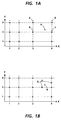
- Figure 1A illustrates the required regular array of data values A0 with example mappings indicated by X's at points a, b, c and d.
- the problem is that printing a color corresponding to mapping O at point e is desired, but when that mapping is interpolated using existing data, it does not provide the expected color.
- mappings P i cannot simply be added to the calibration set, because they will create situations where the region would not be divisible into non-overlapping space filling triangles (or tetrahedrons in the 3-D case).
- two non-overlapping space filling triangles in this region were formed by the points [(3,2), (4,2), (4,3)] and [(3,3), (3,2), (4,3)].
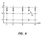
- the set of new points (P i (expanded) ) which we must calculate are shown as solid squares in Figure 4. Initially, these values are based on the set of mappings A0.
- the points which are "near" the new set of measured points are updated by a weighted averaging technique, such as Shepard's Method using data from P i in addition to data from A0.
- mappings which map regular printer signals to empirically derived colorimetric or device independent signals, are used initially in an inverse tetrahedral interpolation process, to produce a mapping of regular colorimetric signals to printer signals. This mapping is then loaded and used, for example to interpolate printer signals to produce an improved response for the color represented by the open circle of Figure 4.
- Figure 5 illustrates the data flow in the system to accomplish the goals of the invention.
- the color space mappings forming mapping set A0 (the flawed mapping) will be used as the basis for creating the new mapping set A1 (the corrected mapping).
- Mappings P i are generated in a standard manner, but are concentrated in color space in the region where any non-linearity was noted.
- the P i mappings (there may be one, or any number required to represent the non-linearity) are directed from interpatch correlation 80, to data expander 200, which can conveniently be a function within LUT processor 100, to produce from the P i values a set of P i(expanded) mappings, including the P i mappings and all the mappings required to fill the array based on the addition of the P i mappings.
- the P i(expanded) mappings are entered into the mapping set A1.
- the new mappings are directed to LUT processor 100, in order to generate a new color transformation LUT for storage at color space transform and color correction 20.
Abstract
Description
- The present invention is directed towards compiling look up tables representative of printer characteristics, to enable the conversion of colors defined in a first color space to colors defined in the printer color space, and more particularly to a method of making such table more linear.
- The generation of color documents can be thought of as a two step process: first, the generation of the image by means of scanning an original document with a color image input terminal or scanner or, alternatively, creating a color image on a work station operated in accordance with a color image creation program; and secondly, printing of that image with a color printer in accordance with the colors defined by the scanner or computer generated image. Scanner output is commonly transformed to a color space of tristimulus values, i.e., RGB (red-green-blue). Commonly, these values are a linear transformation of the standard XYZ coordinates of CIE color space, or a corrected transform of those values. In the case of computer generated images, colors defined by the user at the user interface of a workstation can be defined initially in color space of tristimulus values. These colors are defined independently of any particular device, and accordingly reference is made to the information as being "device independent".
- Printers often have an output which can be defined as existing in a color space called CMYK (cyan-magenta-yellow-key or black) which is uniquely defined for the printer by its capabilities and colorants. Printers operate by the addition of multiple layers of ink or colorant in layers to a page. The response of the printer tends to be relatively non-linear. These colors are defined for a particular device, and accordingly reference is made to the information as being "device dependent". Thus, while a printer receives information in a device independent color space, it must convert that information to print in a device dependent color space, which reflects the gamut or possible range of colors of the printer.
- The desirability of operating in a device independent color space with subsequent conversion to a device dependent color space is well known, as shown by US-A 4,500,919 to Schreiber and US-A 2,790,844 to Neugebauer, and US-A 4,275,413 to Sakamoto. There are many methods of conversion between color spaces, all of which begin with the measurement of printer response to certain input values. Commonly, a printer is driven with a set of input values reflecting color samples throughout the printer gamut, the color samples are printed in normal operation of the printer. As previously noted, most printers have non-linear response characteristics.
- In US-A 4,275,413 to Sakamoto, the information derived is placed into lookup tables, stored in a memory, perhaps ROM memory or RAM memory where the lookup table relates input color space to output color space. The lookup table is commonly a three dimensional table since color is defined with three variables. In RGB space, at a scanner or computer, space can be defined as three dimensional with black at the origin of a three dimensional coordinate system 0,0,0, and white at the maximum of a three dimensional coordinate system which an 8-bit system, would be located at 255, 255, 255. Each of the three axes radiating from the origin point therefore respectively define red, green, and blue. A similar construct can be made for the printer, with axes representing cyan, magenta, and yellow. In the 8-bit system suggested, there will be, however, over 16 million possible colors (256³). There are clearly too many values for a 1:1 mapping of RGB to CMY. Accordingly, as proposed in US-A 4,275,413 to Sakamoto, only a relatively small number of samples are used to do the mapping from RGB to CMY, perhaps on the order of 1,000. Therefore, the lookup tables consist of a set of values which could be said to be the intersections for corners of a set of cubes mounted on top of one another. Colors falling within each cubic volume can be interpolated from the measured values, through many methods including tri-linear interpolation, tetrahedral interpolation, polynomial interpolation, linear interpolation, and any other interpolation method depending on the desired speed and accuracy of the result.
- It would be very easy to index device dependent color values or specifications to device independent color specifications, but that is not the requirement. Instead, device independent specifications must be mapped to device dependent specifications. Several problems arise. Of course, the primary problem is that the printer response is not a linear response. A second problem is that the color space, and therefore the coordinates defined in the color space must be maintained as a uniform grid, for maximum efficiency of some interpolation methods, particularly for tetrahedral interpolation, a very desirable method of interpolation.
- Accordingly, a three dimensional look up table (LUT) may be constructed which puts device independent input values into a predictable grid pattern. One method of accomplishing this requirement is by an interpolation process which derives a value at a desired location as a function of all (or a significant set) of measured color values. One way of doing this is to use Shepard's Method (see, for example "Shepard's Method of 'Metric Interpolation' to Bivariate and Multivariate Interpolation" by W. Gordon and J. Wixom, Mathematics of Computation, Vol. 32, No. 141, January 1978, pp. 253-264). Shepard's Method suggests that a vector can be thought of as defining the difference between an asked-for color which was directed to a printer in the printed color. Then, for any other point in color space which is desired, that point can be thought of as a vector quantity, derived by averaging over the space all the vectors, each vector weighted by a function which decreases its effect on the vector as that vector is further and further away from the point coloring question. In one useful formula, each vector is weighted by a function of ¹/d 4.
- Alternatively the method of Po-Chieh Hung, "Colorimetric Calibration for Scanners and Media", SPIE, Vol. 1448, Camera and Input Scanner System, (1991), describes a method of inverse tetrahedral interpolation, to the same effect as the described Shepard's Method (see also US-A 5,296,923 to Hung). A requirement of this method is that the color space be segmented into a set of non-overlapping, space-filling tetrahedrons. This segmentation requirement is fulfilled by using only data from a full rectangular array of points, where it is easy to define the mesh of points which define the tetrahedrons.
- A problem encountered in the calibration process is that of having most colors being reproduced successfully, but having a few regions of color space that are not well behaved in terms of the empirically derived calibration model. The addition of a few more calibration points in these poorly behaved areas, would appear to be a solution to the problem. However, because inverse tetrahedral interpolation requires a full rectangular grid of data points, to obtain the "few more calibration points" in the poorly behaved areas really requires the addition of hundreds of more calibration points. Figure 1 illustrates the problem in two dimensions for simplicity, where a, b, c and d represent colors which reproduce successfully in a color space transformation, while point e does not. Adding points Pi, as in Figure 1A presumably would resolve the reproduction problem, but that arrangement does not provide a color space which is readily segmentable into a set of non-overlapping, space-filling tetrahedrons. This segmentation requirement is fulfilled by using only data from a full rectangular array of points.
- It is an object of the invention to provide a calibration method providing additional data points to support inverse tetrahedral interpolation for the derivation of color space transformation look up tables, without substantially increasing the amount of empirically measured data.
- In accordance with one aspect of the invention, the color printer calibration method for improving printer accuracy in regions of local non-linearity includes the steps of: a) starting with filled rectangular array of color mappings A₀ mapping printer signals to device independent color space signals; b) empirically deriving a set of color mappings Pi in an area of interest; c) using a set of planes defined by the color mappings of A₀, and the set of empirically derived color mappings Pi, identifying a new set of planes such that each point defined by A₀ and each point defined by Pi is located at the intersection of three planes, the intersection points of this expanded number of planes defining a set of points Pi(expanded) that define a full rectangular array A₁ of mappings including mappings A₀, mappings Pi and mappings Pi(expanded); d) storing said mapping A₁ for use in the creation of a new color space transformation LUT for use with said printer.
- In accordance with another aspect of the invention, the method includes, before step d), the step of substituting into mapping A₁, any empirically derived mappings from A₀ and any empirically derived mappings from Pi.
- In accordance with yet another aspect of the invention, the method includes, before step d), the step of replacing mappings in A₁ that are defined by points from mapping A₀ and near a value of mapping Pi, with new mapping values which take into account the nearby Pi mappings.
- In using the described method, the goal of obtaining a filled rectangular or three dimensional mapping is obtained, while additionally improving calibration results through the use of the new empirical data to describe color mapping adjacent to the new empirical points.
- These and other aspects of the invention will become apparent from the following descriptions to illustrate a preferred embodiment of the invention read in conjunction with the accompanying drawings in which:
- Figures 1A and 1B show the problem addressed by the present invention in a two dimensional example;
- Figures 2 and 3 together illustrate an overall system block diagram showing a color printing system in which the present invention might find use;
- Figure 4 shows the principle of the present invention, whereby after derivation of new empirical values, a new filled rectangular array must be generated; and
- Figure 5 illustrates the construction of the new color calibration mapping using the method and system described herein.
- Referring now to the drawings, a basic system for carrying out the present invention is shown in Figure 2. The system includes a
scanner 10, such as perhaps the color scanner available in the Xerox 5775 digital color copiers, which can be calibrated to produce a set of digital colorimetric or device independent data describing a scannedimage 12, which, by definition can be defined in terms of the colorimetric Ro,Go,Bo space. Resulting from the scanning operation is a set of scanner image signals Rs, Gs, Bs, defined in device dependent scanner terms. Incorporated into the scanner or another processing path is apost-scanning processor 14, which provides correction of scanner image signals Rs, Gs, Bs to colorimetric terms, Rc, Gc, Bc, typically digital in nature. The values may be in terms of CIE color space (r,g,b), or the L*a*b* luminance-chrominance space (LC₁C₂). A color space transform, indicated byblock 20, such as that described in US-A 4,275,413 to Sakamoto, is used to convert the device independent data to device dependent data. The output ofcolor space transform 20 is the image defined in terms of a device dependent space, or colorant driving signal Cp, Mp, Yp, Kp that will be used to drive aprinter 30. In one possible example, the colorant values represent the relative amounts of cyan, magenta, yellow, and black toners that are to be deposited over a given area in an electrophotographic printer, such as, again, Xerox 5775 digital color copiers. The printed output image may be said to be defined in terms of Rp,Gp,Bp, which are hoped to have a relationship with Ro,Go,Bo such that the printed output image has a color that is colorimetrically similar to the original image, although that similarity is ultimately dependent upon the gamut of the printing device. Black addition for under color removal and gray balance processing may also be combined into the color space transform element. Although these features are not required, they are desirable and are illustrated herein. When we refer to colorimetric spaces, we are referring to spaces which are transforms of CIE XYZ space (1931). Such colorimetric spaces are also inherently device independent. When we refer to device dependent space, we refer to a color space which is defined only in terms of operation of the device using it. While many color spaces have three dimensions, it is possible to have color spaces with less than three dimensions or more than three dimensions. - With reference now to Figure 3, and color space transformation and
color correction 20, initially, Rc, Gc, Bc color signals are directed to aninterpolation device 140, which includes a three dimensional lookup table stored in adevice memory 150 such as a RAM or other addressable memory device, which will meet speed and memory requirements for a particular device. Color signals Rc, Gc, Bc are processed to generate address entries to the table which stores a set of transform coefficients with which the Rc, Gc, Bc may be processed to convert them to Cx, Mx, Yx colorant signals or any multi-dimensional output color space including but not limited to CMYK or spectral data. Values which are not mapped may be determined through interpolation. - It will no doubt be recognized that there are many methods of providing a transform from device independent data to device dependent data, with US-A 4,275,413 to Sakamoto describing one method, which itself can be varied. Once a conversion table is established, a method of interpolation referred to as tri-linear or cubic interpolation may also be used to calculate output values from the limited set of input values.
- To create the table, a set of color patches are created, preferably including determined linearization and black addition. This is done by printing and measuring about 1000 to 4000 patches of printer colors distributed throughout the color space, i.e., a large set of printer driving signals are generated, in varying densities of combinations of C,M,Y,K, and used to drive the printer. The color of each patch is measured, using a spectrophotometer to determine color in terms of Rc,Bc,Gc. The measured colors of these patches are used to build a three dimensional lookup table (LUT) relating Rc,Bc,Gc defined colors to CxMxYx defined colors. Conversions that do not include mapped and measured points may be interpolated or extrapolated.
- With reference again to Figure 2, a calibration image is conveniently stored in a device memory such as
calibration ROM 60, RAM, floppy or the like, or are generated on the fly with a predetermined generation function. Signals stored therein are directed to the printer under the control ofprinter controller 65. Spectrophotometer 70 (which can alternatively be a colorimeter, a calibrated densitometer or even a calibrated color scanner) is used to scan the calibration target and produce RoGoBo signal values as a function of sensed density, representing the colors of each scanned patch.Interpatch correlation processor 80 reads the responses provided fromspectrophotometer 70 for each location in the calibration target and correlates the response with the input CMY signals, so that an RcGcBc to CMY mapping is generated. The data derived atinterpatch correlation processor 80 is directed toLUT processor 100, which generates the required lookup tables for storage in color space transform andcolor correction 20. - Now the principle of the present invention will be described with reference to Figure 1A, 1B and Figure 4. Figure 1A is a two dimensional color space example chosen to simplify the more common problem in three dimensions. Figure 1A illustrates the required regular array of data values A₀ with example mappings indicated by X's at points a, b, c and d. The problem is that printing a color corresponding to mapping O at point e is desired, but when that mapping is interpolated using existing data, it does not provide the expected color. If the surrounding mappings at points a(3,3), b(3,2), c(4,2) and d(4,3) are correct or acceptable, it may be concluded that the response of the system in this region of color space is very non-linear, and that linear interpolation from existing data will produce errors in the output. An improved characterization of the system response is required.
- To obtain a better characterization of the printing system in this region, three more color patches are generated (a set referred to as Pi), generally within the limits of the region, and the printer response is measured, as indicated by the hollow squares in Figure 1B. The new patches Pi are located at (x,y) = (3.5, 2) (3.5, 2.75) and (4, 2.5). The actual locations and number of these patches can vary.
- The newly derived mappings Pi cannot simply be added to the calibration set, because they will create situations where the region would not be divisible into non-overlapping space filling triangles (or tetrahedrons in the 3-D case). In the original data set A₀, two non-overlapping space filling triangles in this region were formed by the points [(3,2), (4,2), (4,3)] and [(3,3), (3,2), (4,3)].
- The inventive solution, illustrated in Figure 4, divides the region defined by these points into sets of smaller squares using linear interpolation and weighted averaging to estimate required values. This works in the 2-D case described here, but to maintain continuity across the boundary in the third dimension it is also necessary to add in an entire line (or plane, in the 3-D case) of new data points. That is, we must have a value at x = 3.5 for every possible Y value, and we must have a value at y = 3.5 and y = 3.75 for every possible X value. The set of new points (Pi (expanded)) which we must calculate are shown as solid squares in Figure 4. Initially, these values are based on the set of mappings A₀.
- Note that this process has the effect of maintaining a full and filled rectangular array of points, even though only a few new points on each line (or plane) were measured. The points on the line (or plane) which were not measured are obtained by linear interpolation. This is the same type of interpolation that would have been done later in the use of the data set, and is done in regions where we have not seen a problem with assuming a linear response of the system.
- In addition to adding new data points by linear interpolation, the points which are "near" the new set of measured points (for example; the three points indicated by black squares at (x,y) = (3.5, 2.5), (3.5, 3.0), and (4.0, 2.75) in Figure 1B and Figure 4) are updated by a weighted averaging technique, such as Shepard's Method using data from Pi in addition to data from A₀. Now, the three points at (3.5, 2.5), (3.5, 3.0), and (4.0, 2.75) in Figure 4 will be interpolated or evaluated using the values of (x,y) = (3.5, 2), (3.5, 2.75), (4, 2.5) from the set Pi, and the values at (x,y) = (4,2), and (4,3) from the set A₀. It is believed that using these closer points would produce improved printer signals.
- These newly derived mappings, which map regular printer signals to empirically derived colorimetric or device independent signals, are used initially in an inverse tetrahedral interpolation process, to produce a mapping of regular colorimetric signals to printer signals. This mapping is then loaded and used, for example to interpolate printer signals to produce an improved response for the color represented by the open circle of Figure 4.
- The inventive method of improving printer linearity suggests that: given a filled rectangular array of points A₀ mapping printer signals to device independent or colorimetric color space signals, it is desirable to add some set of points Pi, were i = 1, 2 . . . N, in such a way that a filled rectangular array of points is derived. This requirement is accomplished in four steps:
- 1) Identify a set of planes such that each new point Pi, and each original point defined by A₀ will be located at the intersection of three planes in color space;
- 2) Using the set of points A₀ as a starting condition, interpolate a new set of points A₁, such that each 3 way intersection of the planes found in step 1) has an associated mapping. Initially, all values of A₁ are based on values of A0.
- 3) Any points in A₁ which also have measured values defined by a Pi are updated to the correct (i.e., measured, not interpolated) values of Pi.
- 4) Any points in A₁, which are not part of A₀ or defined by a value Pi, but are near a value of Pi, are modified using nearby points in either A₀ or Pi with Shepard's interpolation, or some other interpolation method. In the example above, any interpolated points contained within or in the box defined by (x, y) = (3,2) and (4,3) are updated using the three new points and the original values at the corners of the box.
- Figure 5 illustrates the data flow in the system to accomplish the goals of the invention. The color space mappings forming mapping set A₀ (the flawed mapping) will be used as the basis for creating the new mapping set A₁ (the corrected mapping). Mappings Pi are generated in a standard manner, but are concentrated in color space in the region where any non-linearity was noted. The Pi mappings (there may be one, or any number required to represent the non-linearity) are directed from
interpatch correlation 80, todata expander 200, which can conveniently be a function withinLUT processor 100, to produce from the Pi values a set of Pi(expanded) mappings, including the Pi mappings and all the mappings required to fill the array based on the addition of the Pi mappings. The Pi(expanded) mappings are entered into the mapping set A₁. - There is likely to be overlap between the A₀ and Pi(expanded) mappings. That overlap can be handled in a two step process: 1) wherever there is an empirically derived mapping of Pi, such empirically derived mapping is substituted in A₁ instead of A₀, and 2) in regions closely adjacent in space to any of the new empirically derived mappings, the interpolated values are modified using the Pi mappings and the A₀ mappings. Points are deemed to be closely adjacent if they fall within a rectangle (or a box in 3-D space) which also contains a new empirically derived mapping. Thus,
arbitrator 202 operates on Pi and A₀ to arbitrate the data which is loaded.Interpolator 204 operates using Pi and A₀ as required byarbitrator 202, to generate new interpolated data for points near the new empirically derived mappings. These functions can be accomplished within function withinLUT processor 100. - The new mappings are directed to
LUT processor 100, in order to generate a new color transformation LUT for storage at color space transform andcolor correction 20. - It will be appreciated that while we have shown the use of the invention in the conversion of a device independent color space to a device dependent color space, the invention applies equally as well to conversions to any transformation from a first space to a second, device independent or device dependent.
- It will be appreciated that the invention can be accomplished with either software, hardware or combination software- hardware implementations.
Claims (9)
- A method of improving calibration in a calibrated color printing system, the color printing system having a calibration derived from a filled rectangular array of color mappings defined by a first color mapping set A₀, in which printer signals are mapped to colorimetric signals throughout the gamut of the color printing system, including the steps of:a) empirically generating a second color mapping set Pi, mapping printer signals to colorimetric signals, said second color mapping set Pi being smaller than the first color mapping set A₀ and overlapping a portion of the printer gamut therewith;b) using said second color mapping set Pi and a first set of planes corresponding to the first color mapping set A₀, identifying an expanded set of planes in which each mapping in the first color mapping set A₀ and each mapping in said second color mapping set Pi are defined by points located at an intersection of three planes, the intersecting points of the expanded number of planes defining a set of points Pi(expanded) corresponding to a third color mapping set Pi(expanded);c) generating a full rectangular array of color mappings defined by color mapping set A₁, from the first color set mapping A₀, said second color set mappings Pi and said third color mapping set Pi(expanded);d) generating a new calibration for said printing system derived from said color mappings A₁.
- The method as defined in claim 1, wherein said step of generating a full rectangular array of color mappings defined by color mapping set A₁ includes the substep of using any empirically derived mapping from color mapping sets A₀ or Pi in place of a non-empirically derived mapping.
- The method as defined in claim 1, wherein said step of generating a full rectangular array of color mappings defined by color mapping set A₁ includes the substep of replacing any mappings in third color mapping set Pi(expanded) that are near mappings of second color mapping set Pi, with mappings which take into account the Pi mappings.
- A calibrated color printing system, the color printing system having a calibration stored in a calibration memory derived from a filled rectangular array of color mappings defined by a first color mapping set A₀, in which printer signals are mapped to colorimetric signals throughout a gamut of the color printing system, including:a) means for empirically generating a second color mapping set Pi, mapping printer signals to colorimetric signals, said second color mapping set Pi being smaller than the first color mapping set A₀ and overlapping a portion of the printer gamut therewith;b) means for using said second color mapping set Pi and a first set of planes corresponding to the first color mapping set A₀, identifying an expanded set of planes in which each mapping in the first color mapping set A₀ and each mapping in said second color mapping set Pi are defined by points located at an intersection of three planes, the intersecting points of the expanded number of planes defining a set of points Pi(expanded) corresponding to a third color mapping set Pi(expanded);c) means for generating a full rectangular array of color mappings defined by color mapping set A₁, from the first color set mapping A₀, said second color set mappings Pi and said third color mapping set Pi(expanded);d) means for generating a new calibration for said printing system derived from said color mappings A₁.
- The device as defined in claim 4, wherein said means for generating a full rectangular array of color mappings defined by color mapping set A₁ includes means for using any empirically derived mapping from color mapping sets A₀ or Pi in place of a non-empirically derived mapping.
- The device as defined in claim 4, wherein said means for generating a full rectangular array of color mappings defined by color mapping set A₁ includes means for replacing any mappings in third color mapping set Pi(expanded) that are near mappings of second color mapping set Pi, with mappings which take into account the Pi mappings.
- A method of recalibrating a color printing system in a color space region of non-linearity, the color printing system having a first calibration stored in a calibration memory, said first calibration being derived from a filled rectangular array of color mappings defined by a first color mapping set A₀, in which printer signals are mapped to colorimetric response signals throughout a gamut of the color printing system, including the steps of:a) directing a correction set of printer signals to said printing system to print a set of color patches with colorants on a medium corresponding to a color space region of non-linearity;b) measuring colorimetric response of said printer in said color space region of non-linearity from said set of color patches and generating colorimetric response signals indicative thereof;c) generating a second color mapping set Pi, mapping the correction set of printer signals to colorimetric response signals, said second color mapping set Pi being smaller than the first color mapping set A₀ and overlapping a portion of the printer gamut therewith;d) using said second color mapping set Pi and a first set of planes corresponding to the first color mapping set A₀, identifying an expanded set of planes in which each mapping in the first color mapping set A₀ and each mapping in said second color mapping set Pi are defined by points located at an intersection of three planes, the intersecting points of the expanded number of planes defining a set of points Pi(expanded) corresponding to a third color mapping set Pi(expanded);e) generating a full rectangular array of color mappings defined by color mapping set A₁, from the first color set mapping A₀, said second color set mappings Pi and said third color mapping set Pi(expanded);f) applying an inverse interpolation process to said color mapping set A₁ to derive a new mapping of colorimetric response signals to printer signals, addressable by said colorimetric response signals, thereby generating a new calibration for said printing system.
- The method as defined in claim 7, wherein said step of generating a full rectangular array of color mappings defined by first color mapping set A₁ includes the substep of using any measured colorimetric response mapping from color mapping sets A₀ or Pi in place of an interpolation derived mapping.
- The method as defined in claim 7, wherein said step of generating a full rectangular array of color mappings defined by color mapping set A₁ includes the substep of replacing any mappings in third color mapping set Pi(expanded) that are near mappings of second color mapping set Pi, with mappings which take into account the Pi mappings.
Applications Claiming Priority (2)
| Application Number | Priority Date | Filing Date | Title |
|---|---|---|---|
| US08/316,968 US5594557A (en) | 1994-10-03 | 1994-10-03 | Color printer calibration correcting for local printer non-linearities |
| US316968 | 1994-10-03 |
Publications (3)
| Publication Number | Publication Date |
|---|---|
| EP0706286A2 true EP0706286A2 (en) | 1996-04-10 |
| EP0706286A3 EP0706286A3 (en) | 1996-12-18 |
| EP0706286B1 EP0706286B1 (en) | 2000-02-09 |
Family
ID=23231507
Family Applications (1)
| Application Number | Title | Priority Date | Filing Date |
|---|---|---|---|
| EP95307011A Expired - Lifetime EP0706286B1 (en) | 1994-10-03 | 1995-10-03 | Color printer calibration correcting for local printer non-linearities |
Country Status (4)
| Country | Link |
|---|---|
| US (1) | US5594557A (en) |
| EP (1) | EP0706286B1 (en) |
| JP (1) | JPH08125880A (en) |
| DE (1) | DE69514977T2 (en) |
Cited By (4)
| Publication number | Priority date | Publication date | Assignee | Title |
|---|---|---|---|---|
| EP1026893A3 (en) * | 1999-01-19 | 2001-11-21 | Xerox Corporation | Distributed digital image processing system |
| WO2006088683A1 (en) * | 2005-02-15 | 2006-08-24 | Eastman Kodak Company | Color correction techniques for correcting color profiles |
| EP2160009A1 (en) * | 2008-08-27 | 2010-03-03 | Canon Kabushiki Kaisha | Method for generating a color chart |
| US7710432B2 (en) | 2005-02-15 | 2010-05-04 | Eastman Kodak Company | Color correction techniques for correcting color profiles or a device-independent color space |
Families Citing this family (48)
| Publication number | Priority date | Publication date | Assignee | Title |
|---|---|---|---|---|
| JP3703162B2 (en) * | 1994-04-22 | 2005-10-05 | キヤノン株式会社 | Image forming apparatus |
| US7031020B1 (en) * | 1994-04-22 | 2006-04-18 | Canon Kabushiki Kaisha | Image processing method, apparatus and controller |
| JP3618837B2 (en) * | 1995-07-20 | 2005-02-09 | キヤノン株式会社 | Image processing apparatus and method, and image forming apparatus |
| JPH09135354A (en) * | 1995-11-10 | 1997-05-20 | Canon Inc | Device and method for processing image |
| US6421140B1 (en) * | 1995-12-08 | 2002-07-16 | Canon Kabushiki Kaisha | Color space conversion with simplified interpolation |
| US6160635A (en) * | 1995-12-27 | 2000-12-12 | Fuji Photo Co., Ltd. | Color conversion method using ordered color signal interpolation |
| US6075888A (en) * | 1996-01-11 | 2000-06-13 | Eastman Kodak Company | System for creating a device specific color profile |
| US5933256A (en) * | 1996-05-14 | 1999-08-03 | Xexox Corporation | Method for color correction within a color space using hue shifting of a region therein |
| JP3943167B2 (en) * | 1996-09-10 | 2007-07-11 | 富士フイルム株式会社 | Color conversion method |
| US6178007B1 (en) * | 1997-01-21 | 2001-01-23 | Xerox Corporation | Method for continuous incremental color calibration for color document output terminals |
| US6137594A (en) * | 1997-03-25 | 2000-10-24 | International Business Machines Corporation | System, method and program for converting an externally defined colorant CMYK into an equivalent colorant (C'M'Y'K') associated with a given printer |
| US6038374A (en) * | 1997-06-04 | 2000-03-14 | Hewlett-Packard Company | System and method for constructing calibrated color tables in color image reproduction systems using stochastic supersampling |
| US5953499A (en) * | 1997-06-27 | 1999-09-14 | Xerox Corporation | Color printing hue rotation system |
| US6181445B1 (en) | 1998-03-30 | 2001-01-30 | Seiko Epson Corporation | Device-independent and medium-independent color matching between an input device and an output device |
| US6204939B1 (en) | 1998-03-30 | 2001-03-20 | Seiko Epson Corporation | Color matching accuracy inside and outside the gamut |
| US6160644A (en) * | 1998-03-30 | 2000-12-12 | Seiko Epson Corporation | Scanner calibration technique to overcome tone inversion |
| US6185004B1 (en) | 1998-03-30 | 2001-02-06 | Seiko Epson Corporation | Self-calibration for color image reproduction system |
| US6048117A (en) * | 1998-05-08 | 2000-04-11 | Xerox Corporation | Network-based system for color calibration of printers |
| US6062137A (en) * | 1998-05-17 | 2000-05-16 | Hewlett-Packard Company | Application of spectral modeling theory in device-independent color space halftoning |
| US6213579B1 (en) | 1998-11-24 | 2001-04-10 | Lexmark International, Inc. | Method of compensation for the effects of thermally-induced droplet size variations in ink drop printers |
| US6211970B1 (en) | 1998-11-24 | 2001-04-03 | Lexmark International, Inc. | Binary printer with halftone printing temperature correction |
| US6330078B1 (en) | 1998-12-09 | 2001-12-11 | Xerox Corporation | Feedback method and apparatus for printing calibration |
| US6404511B1 (en) | 1998-12-11 | 2002-06-11 | Seiko Epson Corporation | Self-calibration of network copier system |
| US6215562B1 (en) | 1998-12-16 | 2001-04-10 | Electronics For Imaging, Inc. | Visual calibration |
| US6360007B1 (en) | 1998-12-22 | 2002-03-19 | Xerox Corporation | Dynamic optimized color lut transformations based upon image requirements |
| US6023351A (en) * | 1998-12-23 | 2000-02-08 | Canon Kabushiki Kaisha | Regularized printer LUT with improved accuracy |
| US6618499B1 (en) * | 1999-06-01 | 2003-09-09 | Canon Kabushiki Kaisha | Iterative gamut mapping |
| US7126705B1 (en) | 1999-08-27 | 2006-10-24 | E. I. Du Pont De Nemours And Company | Method and apparatus for remote printing |
| US6757071B1 (en) | 1999-11-09 | 2004-06-29 | Xerox Corporation | Intelligent printer driver and user interface and method to recommend and/or automatically modify a document for printing, and a method therefore |
| US6809837B1 (en) | 1999-11-29 | 2004-10-26 | Xerox Corporation | On-line model prediction and calibration system for a dynamically varying color reproduction device |
| US6873432B1 (en) | 1999-11-30 | 2005-03-29 | Xerox Corporation | Method and apparatus for representing color space transformations with a piecewise homeomorphism |
| US6714319B1 (en) | 1999-12-03 | 2004-03-30 | Xerox Corporation | On-line piecewise homeomorphism model prediction, control and calibration system for a dynamically varying color marking device |
| US6625306B1 (en) | 1999-12-07 | 2003-09-23 | Xerox Corporation | Color gamut mapping for accurately mapping certain critical colors and corresponding transforming of nearby colors and enhancing global smoothness |
| JP2001275003A (en) * | 2000-03-24 | 2001-10-05 | Fuji Photo Film Co Ltd | Method and device for image correction and recording medium |
| US6771275B1 (en) * | 2000-06-07 | 2004-08-03 | Oak Technology, Inc. | Processing system and method using a multi-dimensional look-up table |
| US7427115B2 (en) | 2002-03-28 | 2008-09-23 | Xerox Corporation | Fluid ejector including a drop size symbol, a method of disposing a drop size symbol in a fluid ejector, and an image forming device including a marking fluid ejector with a drop size symbol |
| US20030184810A1 (en) * | 2002-03-28 | 2003-10-02 | Xerox Corporation | First and second methods for an image forming device to form an image based on a drop size symbol |
| JP2004023740A (en) * | 2002-06-20 | 2004-01-22 | Canon Inc | Data processing apparatus and method, and image processing apparatus |
| US7450226B2 (en) * | 2005-04-15 | 2008-11-11 | Xerox Corporation | Gray balance calibration of an imaging system |
| KR101204452B1 (en) * | 2006-01-19 | 2012-11-26 | 삼성전자주식회사 | Apparatus and method for compensating output image |
| GB0618412D0 (en) * | 2006-09-19 | 2006-11-01 | Punch Graphix Int Nv | Near press 4-color N-color conversion method and system for late binding of press details in a RIP-less color conversion or documented CMYK workflow |
| US20080192309A1 (en) * | 2007-02-09 | 2008-08-14 | Xerox Corporation | Color scan correction method and system |
| US8922853B2 (en) | 2008-05-12 | 2014-12-30 | Wilopen Products Lc | Printer calibration system and associated methods |
| US20100020340A1 (en) * | 2008-07-25 | 2010-01-28 | Xerox Corporation | Method and system for visual calibration of printers |
| US8963947B2 (en) | 2011-01-25 | 2015-02-24 | Dolby Laboratories Licensing Corporation | Enhanced lookup of display driving values |
| JP6683022B2 (en) * | 2016-06-03 | 2020-04-15 | コニカミノルタ株式会社 | Printer, color conversion control program, and color conversion control method |
| WO2018147861A1 (en) * | 2017-02-10 | 2018-08-16 | Hewlett-Packard Development Company, L.P. | Color calibration |
| US20210370604A1 (en) * | 2019-01-31 | 2021-12-02 | Hewlett-Packard Development Company, L.P. | Additive manufacturing system and method |
Citations (3)
| Publication number | Priority date | Publication date | Assignee | Title |
|---|---|---|---|---|
| EP0378448A2 (en) * | 1989-01-13 | 1990-07-18 | Electronics for Imaging, Inc. | Colour image processing |
| EP0398502A2 (en) * | 1989-05-17 | 1990-11-22 | Hewlett-Packard Company | Method and system for providing a colour match between a scanned colour test pattern and the respective printout of a colour printer, using a closed control loop |
| EP0454275A2 (en) * | 1990-04-26 | 1991-10-30 | Bayer Corporation | Color separation method |
Family Cites Families (14)
| Publication number | Priority date | Publication date | Assignee | Title |
|---|---|---|---|---|
| US2790844A (en) * | 1954-05-11 | 1957-04-30 | Adalia Ltd | Color correction selector |
| US4275413A (en) * | 1978-03-30 | 1981-06-23 | Takashi Sakamoto | Linear interpolator for color correction |
| US4500919A (en) * | 1982-05-04 | 1985-02-19 | Massachusetts Institute Of Technology | Color reproduction system |
| US4992861A (en) * | 1988-10-18 | 1991-02-12 | Eastman Kodak Company | Color image reproduction apparatus having a digitally operated look-up table constructed by means of a least squares algorithm |
| US4941039A (en) * | 1989-04-04 | 1990-07-10 | Eastman Kodak Company | Color image reproduction apparatus having a least squares look-up table augmented by smoothing |
| US5311332A (en) * | 1990-12-20 | 1994-05-10 | Ricoh Company, Ltd. | Interpolation method and color correction method using interpolation |
| US5296923A (en) * | 1991-01-09 | 1994-03-22 | Konica Corporation | Color image reproducing device and method |
| US5428465A (en) * | 1991-08-12 | 1995-06-27 | Matsushita Electric Industrial Co., Ltd. | Method and apparatus for color conversion |
| US5305119A (en) * | 1992-10-01 | 1994-04-19 | Xerox Corporation | Color printer calibration architecture |
| US5390035A (en) * | 1992-12-23 | 1995-02-14 | International Business Machines Corporation | Method and means for tetrahedron/octahedron packing and tetrahedron extraction for function approximation |
| US5323249A (en) * | 1993-01-12 | 1994-06-21 | E. I. Du Pont De Nemours And Company | Method for reproducing color images having one color gamut with a device having a different color gamut |
| US5377041A (en) * | 1993-10-27 | 1994-12-27 | Eastman Kodak Company | Method and apparatus employing mean preserving spatial modulation for transforming a digital color image signal |
| US5416613A (en) * | 1993-10-29 | 1995-05-16 | Xerox Corporation | Color printer calibration test pattern |
| US5471324A (en) * | 1994-04-05 | 1995-11-28 | Xerox Corporation | Color printer calibration with improved color mapping linearity |
-
1994
- 1994-10-03 US US08/316,968 patent/US5594557A/en not_active Expired - Lifetime
-
1995
- 1995-09-27 JP JP7249202A patent/JPH08125880A/en active Pending
- 1995-10-03 EP EP95307011A patent/EP0706286B1/en not_active Expired - Lifetime
- 1995-10-03 DE DE69514977T patent/DE69514977T2/en not_active Expired - Lifetime
Patent Citations (3)
| Publication number | Priority date | Publication date | Assignee | Title |
|---|---|---|---|---|
| EP0378448A2 (en) * | 1989-01-13 | 1990-07-18 | Electronics for Imaging, Inc. | Colour image processing |
| EP0398502A2 (en) * | 1989-05-17 | 1990-11-22 | Hewlett-Packard Company | Method and system for providing a colour match between a scanned colour test pattern and the respective printout of a colour printer, using a closed control loop |
| EP0454275A2 (en) * | 1990-04-26 | 1991-10-30 | Bayer Corporation | Color separation method |
Cited By (4)
| Publication number | Priority date | Publication date | Assignee | Title |
|---|---|---|---|---|
| EP1026893A3 (en) * | 1999-01-19 | 2001-11-21 | Xerox Corporation | Distributed digital image processing system |
| WO2006088683A1 (en) * | 2005-02-15 | 2006-08-24 | Eastman Kodak Company | Color correction techniques for correcting color profiles |
| US7710432B2 (en) | 2005-02-15 | 2010-05-04 | Eastman Kodak Company | Color correction techniques for correcting color profiles or a device-independent color space |
| EP2160009A1 (en) * | 2008-08-27 | 2010-03-03 | Canon Kabushiki Kaisha | Method for generating a color chart |
Also Published As
| Publication number | Publication date |
|---|---|
| EP0706286A3 (en) | 1996-12-18 |
| EP0706286B1 (en) | 2000-02-09 |
| JPH08125880A (en) | 1996-05-17 |
| US5594557A (en) | 1997-01-14 |
| DE69514977D1 (en) | 2000-03-16 |
| DE69514977T2 (en) | 2000-07-20 |
Similar Documents
| Publication | Publication Date | Title |
|---|---|---|
| EP0706286B1 (en) | Color printer calibration correcting for local printer non-linearities | |
| US5483360A (en) | Color printer calibration with blended look up tables | |
| US5689350A (en) | Color printer calibration method for accurately rendering selected colors | |
| US5471324A (en) | Color printer calibration with improved color mapping linearity | |
| US5305119A (en) | Color printer calibration architecture | |
| US5416613A (en) | Color printer calibration test pattern | |
| US6360007B1 (en) | Dynamic optimized color lut transformations based upon image requirements | |
| EP0854638B1 (en) | A method for continuous incremental color calibration for color document output terminals | |
| US6441923B1 (en) | Dynamic creation of color test patterns based on variable print settings for improved color calibration | |
| US5185661A (en) | Input scanner color mapping and input/output color gamut transformation | |
| EP0700198B1 (en) | System for correcting color images using tetrahedral interpolation over a hexagonal lattice | |
| US5710824A (en) | System to improve printer gamut | |
| US6381037B1 (en) | Dynamic creation of color test patterns for improved color calibration | |
| US6404517B1 (en) | Color-patch sheet registration | |
| US7327875B2 (en) | Method and apparatus for color conversion | |
| EP0647061B1 (en) | Color space conversion | |
| US6222648B1 (en) | On line compensation for slow drift of color fidelity in document output terminals (DOT) | |
| EP0681396A2 (en) | Method and apparatus for calibrating a four color printer | |
| US7215440B2 (en) | Fast interpolation of large color lookup tables | |
| JP4164214B2 (en) | Color processing apparatus and method | |
| JP4501321B2 (en) | Color gamut compression method | |
| US8630031B1 (en) | Color adjustment for a scanned image |
Legal Events
| Date | Code | Title | Description |
|---|---|---|---|
| PUAI | Public reference made under article 153(3) epc to a published international application that has entered the european phase |
Free format text: ORIGINAL CODE: 0009012 |
|
| AK | Designated contracting states |
Kind code of ref document: A2 Designated state(s): DE FR GB |
|
| PUAL | Search report despatched |
Free format text: ORIGINAL CODE: 0009013 |
|
| AK | Designated contracting states |
Kind code of ref document: A3 Designated state(s): DE FR GB |
|
| 17P | Request for examination filed |
Effective date: 19970618 |
|
| GRAG | Despatch of communication of intention to grant |
Free format text: ORIGINAL CODE: EPIDOS AGRA |
|
| 17Q | First examination report despatched |
Effective date: 19990421 |
|
| GRAG | Despatch of communication of intention to grant |
Free format text: ORIGINAL CODE: EPIDOS AGRA |
|
| GRAH | Despatch of communication of intention to grant a patent |
Free format text: ORIGINAL CODE: EPIDOS IGRA |
|
| GRAH | Despatch of communication of intention to grant a patent |
Free format text: ORIGINAL CODE: EPIDOS IGRA |
|
| GRAA | (expected) grant |
Free format text: ORIGINAL CODE: 0009210 |
|
| AK | Designated contracting states |
Kind code of ref document: B1 Designated state(s): DE FR GB |
|
| REF | Corresponds to: |
Ref document number: 69514977 Country of ref document: DE Date of ref document: 20000316 |
|
| ET | Fr: translation filed | ||
| PLBE | No opposition filed within time limit |
Free format text: ORIGINAL CODE: 0009261 |
|
| STAA | Information on the status of an ep patent application or granted ep patent |
Free format text: STATUS: NO OPPOSITION FILED WITHIN TIME LIMIT |
|
| 26N | No opposition filed | ||
| REG | Reference to a national code |
Ref country code: GB Ref legal event code: IF02 |
|
| PGFP | Annual fee paid to national office [announced via postgrant information from national office to epo] |
Ref country code: GB Payment date: 20130923 Year of fee payment: 19 |
|
| PGFP | Annual fee paid to national office [announced via postgrant information from national office to epo] |
Ref country code: DE Payment date: 20130920 Year of fee payment: 19 Ref country code: FR Payment date: 20131028 Year of fee payment: 19 |
|
| REG | Reference to a national code |
Ref country code: DE Ref legal event code: R119 Ref document number: 69514977 Country of ref document: DE |
|
| GBPC | Gb: european patent ceased through non-payment of renewal fee |
Effective date: 20141003 |
|
| PG25 | Lapsed in a contracting state [announced via postgrant information from national office to epo] |
Ref country code: GB Free format text: LAPSE BECAUSE OF NON-PAYMENT OF DUE FEES Effective date: 20141003 Ref country code: DE Free format text: LAPSE BECAUSE OF NON-PAYMENT OF DUE FEES Effective date: 20150501 |
|
| REG | Reference to a national code |
Ref country code: FR Ref legal event code: ST Effective date: 20150630 |
|
| PG25 | Lapsed in a contracting state [announced via postgrant information from national office to epo] |
Ref country code: FR Free format text: LAPSE BECAUSE OF NON-PAYMENT OF DUE FEES Effective date: 20141031 |