EP0705012A2 - Computer network gateway - Google Patents
Computer network gateway Download PDFInfo
- Publication number
- EP0705012A2 EP0705012A2 EP95306439A EP95306439A EP0705012A2 EP 0705012 A2 EP0705012 A2 EP 0705012A2 EP 95306439 A EP95306439 A EP 95306439A EP 95306439 A EP95306439 A EP 95306439A EP 0705012 A2 EP0705012 A2 EP 0705012A2
- Authority
- EP
- European Patent Office
- Prior art keywords
- protocol
- complement
- fsms
- fsm
- network
- Prior art date
- Legal status (The legal status is an assumption and is not a legal conclusion. Google has not performed a legal analysis and makes no representation as to the accuracy of the status listed.)
- Granted
Links
Images


Classifications
-
- H—ELECTRICITY
- H04—ELECTRIC COMMUNICATION TECHNIQUE
- H04L—TRANSMISSION OF DIGITAL INFORMATION, e.g. TELEGRAPHIC COMMUNICATION
- H04L12/00—Data switching networks
- H04L12/66—Arrangements for connecting between networks having differing types of switching systems, e.g. gateways
-
- H—ELECTRICITY
- H04—ELECTRIC COMMUNICATION TECHNIQUE
- H04L—TRANSMISSION OF DIGITAL INFORMATION, e.g. TELEGRAPHIC COMMUNICATION
- H04L9/00—Cryptographic mechanisms or cryptographic arrangements for secret or secure communications; Network security protocols
- H04L9/40—Network security protocols
Definitions
- Protocol converters based on formal specifications has the following advantages: (1) the operation of the protocol conversion can be proved correct; (2) the protocol converter can be constructed in a relatively short period of time; and (3) the protocol converter can be changed quickly to adapt to changes in the protocol specification.
- most currently existing automatic synthesis techniques are relatively complex and inefficient due to a lack of effective procedures that can handle large realistic protocols, as well as due to the difficulty in preparing the formal specifications of the protocols.
- the protocol circuit A1 100 and the interface protocol circuit A2 125 perform the communication functions of the protocol A as modeled by the corresponding set of FSMs.
- the determination as to which FSM of the set of protocol FSMs is to be implemented in which of the circuits A1 100 or A2 125 would be readily apparent to those skilled in the art.
- the functions specified by the FSMs of the set that are used to communicate with the users and upper-level of the network are implemented in the circuit A1 100.
- those functions characterized by the FSMs of the set that facilitate communication with other networks are implemented in the circuit A2 125.
- An example of the arrangement of the functions of the various FSMs in the respective protocol circuits is described below with respect to FIG. 29.
- FSMs characterizing the service operations provided to the users by the protocols A and B will be referred to by the symbols S A and S B , respectively.
- the input-output operations depicted by the FSMs S A and S B are the service primitives of the protocols A and B, respectively.
- the set of input-output operations of the circuits A1 100 and A2 125 with their respective local user or upper-levels will be referred as IA1 and IA2, respectively.
- An example of this type of input-output operation includes !deliver (data) where a service primitive delivery is used to deliver a message data .
- the set of input-output operations of the circuits B1 140 and B2 165 with their respective local users or upper-levels will be referred to as IB1 and IB2, respectively.
- the circuit A1 100 may be given a service primitive for establishing a connection.
- the circuit A1 100 would generate a corresponding output operation to the circuit A2 125.
- the circuit A2 125 would generate a service primitive indicating to its local user, the interface converter IC 135, that a remote user to the circuit A1 100 wishes to establish a connection.
- the interface converter IC 135 Upon receiving this service primitive, the interface converter IC 135 would generate an input service primitive for the protocol B indicating that a local user, the circuit A2 125, wants to establish a connection.
- the complement protocol FSMs P B-A and P A-B can be generated by performing the method 300 twice, a first time with the protocol P being the protocol B and with the service FSM S being the service FSM S B-A , and a second time with the protocol P being the protocol A and with the service FSM S being the service FSM S A-B .
- Each end entity 710 of the FABP in FIG. 13 employs two methods of acknowledging receipt of data messages with the appropriate sequence number.
- the receiver function FSM Frec uses the FSM Buf of FIG. 19 and associated FSM Atimer of FIG. 20 to generate acknowledgement signals ack0 and ack1.
- a second method of acknowledging receipt of a data message is to piggy-back acknowledgement signals on return data messages.
- the FSM Atimer of FIG. 20 is pruned out of existence, while the sequence number storage FSM NS of FIG. 18 and retransmission timer FSM Retimer of FIG. 15 remain fully intact in forming the pruned counterparts in FIGS. 27 and 24.
- the pruned FSMs for the complement protocol P B-A in FIGS. 23-28 provide only those data transfer functions in the reverse direction.
- the last step 240 of the method 200 is to construct the protocol converter 50 and network end nodes 30 and 40 according to the generated complement protocols in the manner shown in FIG. 2.
- the circuit B1 140 of the protocol converter 50 is directly connected to a second network end node 40.
- the network end node 40 consists of the protocol circuit B2 165 which performs the identical operation of the circuit B1 140 in the protocol converter 50. Full-duplex communication between the circuits 140 and 165 occur over communication channels C F12 and C F21 .
- the circuit B2 165 is also connected to the network 20.
Abstract
Description
- This invention relates to gateways between computer networks, and more particularly to the synthesis of a gateway system that permits users of the associated networks to transmit and receive information through the gateway system using services available on either network.
- Computer networks and other data communication networks that employ communication protocols, such as Systems Network Architecture (SNA), DECNET, and Open Systems Architecture (OSI), are currently utilized around the world. A network protocol is a well defined set of rules governing the syntax, semantics and timing of the data transmission on the network. With the widespread use of electronic mail and file transfer services, it has become increasingly important to provide interconnections between networks. Three commonly used types of network interconnections are bridges, routers and gateways.
- Conventional network interconnection systems typically have been built using ad hoc techniques. Problems in automatically synthesizing interconnections include overcoming network architectural mismatches and designing the protocol converters between the networks. Architectural mismatches involve differences in network layer functionalities, bit rates, buffering, interfaces and hand-off procedures. Since considerable judgment, trade-off, analysis, and decision making is required to overcome architectural mismatches, automatic generation of systems to overcome the architectural mismatches is not foreseeable in the near future.
- Protocol converters translate messages from one protocol to another to rectify any mismatches between network protocols. Recently, techniques have been developed that automatically generate a protocol converter from formal specifications of the corresponding network protocols. Known automatic generation techniques include those described in S. Lam, "Protocol Conversion," IEEE Trans. Soft. Engr., Vol. 14, No. 3, pp. 353-362, March 1988 (an earlier version was presented at SIGCOMM '86); and Y.W. Yao, W.S. Chen, and M.T. Liu, "A Modular approach to constructing Protocol Converters," Proc. INFOCOM '90, pp. 572-579, June 1990.
- Automatic generation of protocol converters based on formal specifications has the following advantages: (1) the operation of the protocol conversion can be proved correct; (2) the protocol converter can be constructed in a relatively short period of time; and (3) the protocol converter can be changed quickly to adapt to changes in the protocol specification. However, most currently existing automatic synthesis techniques are relatively complex and inefficient due to a lack of effective procedures that can handle large realistic protocols, as well as due to the difficulty in preparing the formal specifications of the protocols.
- However, an example of an efficient automatic synthesis technique is described in D.M. Kristol, D. Lee, A.N. Netravali, and K. Sabnani, "A Polynomial time Algorithm for computing Protocol Converters from Formal Specifications," IEEE/ACM Transactions on Networking, pp. 217-229, April 1993, and in U.S. Patent No. 5,327,544, which is assigned to the assignee of the present invention. Both of these references are hereby incorporated by reference. The automatic synthesis technique described in these references generates a protocol converter that provides the greatest common subset of services available on the associated network protocols. This common subset of services is available to users that transmit and receive information through the protocol converter. Typical network services include data transfer, database inquiries and file transfers.
- However, this technique is not transparent to users on either network because all the services available to the users on that network may not be part of the implemented subset in the protocol converter, and thereby not useable when communicating through the protocol converter. Therefore, a need exists for a method of automatically generating a gateway system having a protocol converter that provides a super-set of services to network users that transmit and receive information through the gateway system.
- A gateway system for connecting first and second communication networks according to one embodiment of the invention may include first and second network-end nodes and a protocol converter. Such a gateway system employs associated complement protocol circuits in the end nodes and the protocol converter to provide those services of one protocol that are not provided by the protocol of the corresponding network attached to that end node. As a consequence, the gateway system provides a super-set of services of both network protocols to users of both networks in communicating through the gateway system.
- A method for generating a gateway system between first and second networks according to an embodiment of the invention first determines a common subset of services equal to an intersection of services provided by the protocols. Finite state machines ("FSM") are then generated which characterize first and second complement protocols of those services provided by the network protocols. The first complement service FSM contains those services provided by the second network protocol that are not provided by the first network protocol. Likewise, the second complement service protocol contains those services provided by the first network protocol and not the second network protocol.
- Sets of intercommunicating finite state machines representing each network protocol are then pruned to provide first and second complement network protocol finite state machines. The end nodes and protocol converter are then constructed using circuits that perform the operations of the sets of protocol finite state machines for the protocols, and the first and second complement network protocol finite state machines, as well as an interface converter. The method for generating the gateway system is simple, efficient, and can be accomplished in a polynomial-based number of steps.
- The above-discussed features, as well as additional features and advantages of the present invention, will become more readily apparent by reference to the following detailed description and the accompanying drawings.
-
- FIG. 1 is a schematic diagram of two data communication networks interconnected by a gateway system according to the present invention;
- FIG. 2 is a detailed schematic diagram of a protocol converter and associated network end nodes in the gateway system of FIG. 1;
- FIG. 3 is a flow diagram of the method for generating the gateway system of FIGS. 1 and 2;
- FIG. 4 is a flow diagram of a method for pruning a protocol to generate a complement protocol for use in the method of FIG. 3;
- FIG. 5 is a block diagram of a model arrangement of component finite state machines ("FSMs") to characterize a communication protocol that may be used in generating the gateway system of FIG. 1;
- FIG. 6 is a transmitter FSM for use in a half-duplex alternating bit protocol (HABP) which may be implemented in one of the networks of FIG. 1;
- FIG. 7 is a receiver FSM for use in the HABP;
- FIG. 8 is a FSM for a first communications channel in the HABP;
- FIG. 9 is a FSM for a channel communications channel in the HABP;
- FIG. 10 is a FSM for a timer associated with the transmitter FSM of FIG. 6;
- FIG. 11 is a service FSM for the HABP;
- FIG. 12 is an arrangement of the FSMs for the HABP of FIGS. 6-11 according to the organization of FIG. 5;
- FIG. 13 is a block diagram of an arrangement of component FSMs characterizing a full-duplex alternating bit protocol (FABP) which may be implemented in one of the networks of FIG. 1;
- FIG. 14 is a transmitter FSM for use in the FABP;
- FIG. 15 is a data retransmission timer FSM associated with the FSM of FIG. 14;
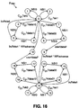
- FIG. 16 is a receiver FSM for use in the FABP;
- FIG. 17 is a sequence number storage FSM associated with the receiver FSM of FIG. 16;
- FIG. 18 is a sequence number storage FSM associated with the transmitter FSM of FIG. 14;
- FIG. 19 is a FSM for generating an acknowledgement signal associated with the receiver FSM of FIG. 16;
- FIG. 20 is an acknowledgement timer associated with the FSM of FIG. 19;
- FIG. 21 is a service FSM for the FABP;
- FIG. 22 is a complement service generated according to the method of FIG. 3 based on the service FSMS of FIGs. 11 and 12;
- FIG. 23 is a pruned transmitter FSM generated according to the method of FIG. 4 based on the FSM of FIG. 14;
- FIG. 24 is a pruned data retransmission timer FSM generated according to the method of FIG. 4 based on the FSM of FIG. 15;
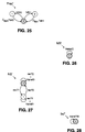
- FIG. 25 is a pruned receiver FSM generated according to the method of FIG. 4 based on the FSM of FIG. 16;
- FIG. 26 is a pruned sequence number storage FSM generated according to the method of FIG. 4 based on the FSM of FIG. 17;
- FIG. 27 is a pruned sequence number storage FSM generated according to the method of FIG. 4 based on the FSM of FIG. 18;
- FIG. 28 is a pruned FSM for generating an acknowledgement signal generated according to the method of FIG. 4 based on the FSM of FIG. 19; and
- FIG. 29 is a block diagram of a gateway system between a HABP network and a FABP network employing the FSMs of FIGS. 14-28 arranged according to the present invention.
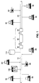
- An embodiment of an interconnection of two networks by a
gateway system 1 according to the present invention is shown in FIG. 1. In FIG. 1, first and seconddata communications networks network end nodes end nodes protocol converter 50 by first andsecond communications channels gateway system 1 consists of theend nodes protocol converter 50. - Each one of the
data communications networks respective computers 80,printers 90,file servers 100 and otherdata storage devices 110. Additional suitable data communication equipment may also be attached to thenetworks data communications network 10 employs a protocol A and the seconddata communications network 20 employs a protocol B. - The operations of a network protocol may be modeled by a set of intercommunicating finite state machines (FSMs). Exemplary sets of FSMs characterizing half-duplex and full-duplex communication protocols are depicted in FIGS. 6-11 and 14-21, respectively, which are described in greater detail below. In the following description, interprocess input-output operation notation similar to that used in the language CSP is used to specify the intercommunication between protocol FSMs. CSP stands for Communicating Sequential Processes which is described in C.A.R. Hoare, "Communicating Sequential Processes," Communications of the ACM, Vol. 21, No. 8, pp. 666-677, August 1978 ("Communicating Sequential Processes").
- According to this notation, a FSM sends a message to other FSMs by means of an "output operation" designated by the symbol "!". Where, for example, there are two FSMs,
machine # 1 andmachine # 2, an output operation inmachine # 1 which sends the message "msg" tomachine # 2 is denoted by machine2!msg. An FSM is also capable of receiving messages. For each message that is sent by one FSM there must be a receipt of the message by at least one other FSM. A FSM receives a message from another FSM by means of an "input operation" designated by the symbol "?". With respect to the output operation exemplified above, the corresponding input operation inmachine # 2 is denoted by machine1?msg, which means receive the message "msg" frommachine # 1. - The operations machine1?msg and machine2!msg are executed simultaneously because they represent different perspectives of the same event. Neither operation can be executed individually. Thus, if a first FSM attempts to do an output operation, it has to wait until a second FSM is ready to execute the corresponding input operation. The synchronized message exchange between two FSMs is called a rendezvous.
- If the FSM name is not specified in an input or output operation, then the input-output operation can take place with any other FSM that is ready to execute the corresponding operation. For example, if a FSM has an operation ?msg, then the receipt of "msg" from any other FSM will trigger the operation of the FSM. These types of input-output operations are often used to model a protocol's interactions with multiple users on multiple communication channels.
- A typical FSM for use in an embodiment of this invention is a four-tuple F = (Σ, V⁻, ρ, s₀) where the symbol Σ is a set consisting of all the FSM's input-output operations and an internal operation; the symbol V is a finite set of states that the FSM may be in; the symbol ρ is a finite set of state transition functions, such as machine!msg or machine?msg; and the symbol s₀ is the initial state of the FSM F. While doing an internal transition from one state to another state, a FSM makes a state transition without interacting with any other FSM. For more information regarding FSMs see Z. Kohavi, Switching Theory and Finite Automata Theory, McGraw-Hill, pp. 275-315 (1978) and Communicating Sequential Processes.
- A FSM may be represented as a directed graph (V,E) where the symbol V is the set of states in the FSM and the symbol E is the set of edges or possible state transitions between states. Each state of a FSM is represented in a directed graph by a circle encircling the designation of the state, such as the
state 900 in the state machine Htrans of FIG. 6. Each edge is labeled by an input-output operation, belonging to the set Σ, which either triggers the state transition or is a result of the state transition. For example,edge 910 extending fromstate 900 in FIG. 6 is labeled with ?timeout. Additionally, an edge may be labeled by two or more input-output operations which independently, or in conjunction, trigger the state transition, or are the result of it. - For notational purposes, an edge labeled by a*b denotes an edge triggered by an input-output operation a followed by an input-output operation b. The symbol "*" represents the boolean AND operator. Therefore, a state transition, represented by an edge labeled by ?ack0*?cancel is only triggered by the receipt of the messages "ack0" and "cancel". A state transition represented by an edge labeled by ?ack0*!start is triggered by the receipt of the message ack0 and the sending of the message start. An edge labeled by a + b denotes two edges that connect the same two states, one labeled by the input-output operation a and one labeled by the input-output operation b. The symbol "+" represents the boolean OR operator. For example, a state transition represented by an edge labeled ?ack1 + ?start is triggered by the receipt of either of the messages "ack1" or "start".
- A FSM always starts in its initial state s₀. The initial state is labeled 0 and may be additionally designated in the directed graph representing the FSM by the presence of a concentric circle surrounding the 0. When the FSM is in any given state it can execute any of the operations that label a transition from that state.
- A protocol provides one or more services to the user of the protocol. These services are also represented as a FSM called the service FSM. However, there is not necessarily a one-to-one mapping or correlation between the set of services provided by a protocol and the set of FSMs that can represent the protocol operation. The input-output operations of the protocol represented by the service FSM are called service primitives of the protocol. According to international standards, a service primitive means an abstract message exchange between the protocol and its user or upper layer. An example of a service primitive is !send(data) where the primitive send is used to transmit a message data.
- If an edge in one FSM is labeled by an input-output operation that has no corresponding operation in another FSM, the transition can never occur. For example, if an edge in
machine # 1 is labeled machine2!msg, andmachine # 2 contains no edge labeled machine1?msg, the transition in machine1 can never occur. This characteristic of communicating FSMs is utilized in the method for generating a gateway system according to the present invention. - For any two FSMs F₁ and F₂, a FSM designated F₁ # F₂ can be built that corresponds to the joint behavior of F₁ and F₂. The FSM F₁ # F₂ is called a reachable FSM, or a composition of F₁ and F₂. The process of constructing F₁ # F₂ from the components F₁ and F₂ is called the reachability computation, or composing, and is well known in the art. Finding the reachable FSM is done by computing the reachable global states. A global state for F₁ # F₂ is defined as a two-tuple (s₁, s₂), where s₁ is the current state of F₁ and s₂ is the current state of F₂. Computation of the reachable global states is described in G.v. Bochmann and C.A. Sunshine, "A Survey of Formal Methods," Computer Networks and Protocols, P.E. Green (Ed.), pp. 561-578, Plenium Press, May 1983.
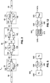
- A more detailed view of the
gateway system 1 of FIG. 1 is shown in FIG. 2. In FIG. 2, thedata communications network 10 is connected to aprotocol circuit A₁ 100 and a complementprotocol circuit P B-A,1 105 in thenetwork end node 30. Within thenetwork end node 30, thecircuits A₁ 100 andP B-A,1 105 are connected to a first combined multiplexer-demultiplexer (MUX-DEMUX) 110. - The
protocol circuit A₁ 100 performs the operations specified in a portion of the set of protocol FSMs that characterize the protocol A and is described in greater detail below. The complementprotocol circuit P B-A,1 105 performs operations that are specified in a portion of a set of complement protocol FSMs characterizing a complement protocol PB-A. The complement protocol PB-A provides those services of the protocol B implemented on thenetwork 20 that are not provided by the protocol A of thenetwork 10. The complementprotocol circuit P B-A,1 105 and complement protocol PB-A are also described in greater detail below. - The MUX-
DEMUX 110 is also connected to thefirst communications channel 60 which is connected to a second MUX-DEMUX 120 disposed in theprotocol converter 50. Within theprotocol converter 50, the MUX-DEMUX 120 is connected to an interfaceprotocol circuit A₂ 125 and an interface complementprotocol circuit P B-A,2 130. The interfaceprotocol circuit A₂ 125 performs those operations characterized in the remainder portion, the set of FSMs for the protocol A that is not performed by theprotocol circuit A₁ 100, and is described in greater detail below. Likewise, the interface complementprotocol circuit P B-A,2 130 performs those operations characterized in the remainder portion of the set of FSMs for the complement protocol PB-A that are not performed by the complementprotocol circuit P B-A,1 105. The interface complementprotocol circuit P B-A,2 130 is also described in greater detail below. The MUX-DEMUXs communications channel 60 between thecircuits A₁ 100 andA₂ 125, and between thecircuits P B-A,1 105 andP B-A,2 130, respectively. - Within the
gateway protocol converter 50, thecircuits A₂ 125 andP B-A,2 130 are connected to aninterface converter IC 135. Theinterface converter IC 135 is further connected to the interfaceprotocol circuit B₁ 140 and an interface complementprotocol circuit P A-B,1 145 which are described in greater detail below. Thecircuits B₁ 140 andP A-B,1 145 are connected to a third MUX-DEMUX 150 which is connected to thesecond communications channel 70. - The
communications channel 70 is further connected to a fourth MUX-DEMUX 160 contained in thenetwork end node 40. Within thenetwork end node 40, the MUX-DEMUX 160 is connected to theprotocol circuit B₂ 165 and a complementprotocol circuit P A-B,2 170. The circuits B₂ and PA-B,2 are also connected to the seconddata communications network 20. - The
protocol circuit A₁ 100 and the interfaceprotocol circuit A₂ 125 perform the communication functions of the protocol A as modeled by the corresponding set of FSMs. The determination as to which FSM of the set of protocol FSMs is to be implemented in which of thecircuits A₁ 100 orA₂ 125 would be readily apparent to those skilled in the art. Generally, the functions specified by the FSMs of the set that are used to communicate with the users and upper-level of the network are implemented in thecircuit A₁ 100. Correspondingly, those functions characterized by the FSMs of the set that facilitate communication with other networks are implemented in thecircuit A₂ 125. An example of the arrangement of the functions of the various FSMs in the respective protocol circuits is described below with respect to FIG. 29. - The interface
protocol circuit B₁ 140 and theprotocol circuit B₂ 165 operate according to the protocol B as specified in the corresponding set of FSMs in an analogous manner to that of thecircuits A₂ 125 andA₁ 100, respectively. Likewise, the functions of the complement protocols PB-A and PA-B, which are characterized by the respective sets of FSMs are divided between thecircuits P B-A,1 105 andP B-A,2 130, and between theP A-B,1 145 andP A-B,2 170, respectively. In a similar manner to that stated above, the complement protocol PA-B characterizes the operations of those services provided by the protocol A that are not present in the protocol B. - By properly arranging the protocol and complement protocol functions in the
end nodes protocol converter 50, thegateway system 1 of FIG. 2 enables users attached to thenetwork 10 to utilize all the services, or a super-set of the services, of the protocols A and B when communicating with thenetwork 20. Likewise, users attached to thenetwork 20 may utilize all the services of the protocols A and B when communicating with thenetwork 10. - In operation, a service provided by both the protocols A and B is performed by a tandem combination of the exchange of corresponding service primitives between
circuits A₂ 125 andB₁ 140 through theinterface converter IC 135 in FIG. 2. In a similar manner, a service provided by the protocol A but not by the protocol B is performed by a tandem combination of the exchange of corresponding service primitives betweencircuits A₂ 125 andP A-B,1 145 through theinterface converter IC 135. A service provided by the protocol B but not by the protocol A is performed by a tandem combination of the exchange of corresponding service primitives betweencircuits B₁ 140 andP B-A,2 130 through theinterface converter IC 135. - Accordingly, the
interface converter IC 135 identifies the service process that is attempting to communicate through theprotocol converter 50. Theinterface converter IC 135 then routes the respective service primitives of that service between the appropriate circuits in theprotocol converter 50. A suitable circuit for performing the operations of theinterface converter IC 135 is a microprocessor or microcontroller connected to memory containing a mapping table for corresponding service primitives. An ASIC or PLA possessing the required routing capabilities may also be employed as theinterface converter IC 135. - By utilizing the MUX-
DEMUXs circuits A₁ 100 andP B-A,1 105,A₂ 125 andP B-A,2 130,B₁ 140 andP A-B,1 145, andB₂ 165 andP A-B,2 170, may be performed in parallel. One suitable technique for ensuring that messages will be exchanged only between protocol circuits, such ascircuits A₁ 100 andA₂ 125, and between complement protocol circuits, such ascircuits P B-A,1 105 andP B-A,2 130, is to use tags, such as a 1 or 2, to denote whether the message transmitted over the communications channel is from a respective protocol or complement protocol circuit. In an alternative embodiment, the MUX-DEMUXs - The
protocol circuit A₁ 100 and the complementprotocol circuit P B-A,1 105, as well as the MUX-DEMUX 110 in theend node 30 may be arranged as separate or combined circuits. Further, the separate or combined circuits may be conventional microprocessors, ASICs or PLAs. The circuits of theprotocol converter 50 andend node 40 may also be implemented as separate or various configurations of combined circuits in a similar manner. - FSMs characterizing the service operations provided to the users by the protocols A and B will be referred to by the symbols SA and SB, respectively. The input-output operations depicted by the FSMs SA and SB are the service primitives of the protocols A and B, respectively. The set of input-output operations of the
circuits A₁ 100 andA₂ 125 with their respective local user or upper-levels will be referred as IA₁ and IA₂, respectively. An example of this type of input-output operation includes !deliver (data) where a service primitive delivery is used to deliver a message data. In a similar manner, the set of input-output operations of thecircuits B₁ 140 andB₂ 165 with their respective local users or upper-levels will be referred to as IB₁ and IB₂, respectively. - For exemplary purposes, suppose the services provided by the protocols A and B are both data transfer protocols. In operation, the
circuit A₁ 100 may be given a service primitive for establishing a connection. In response, thecircuit A₁ 100 would generate a corresponding output operation to thecircuit A₂ 125. Thecircuit A₂ 125 would generate a service primitive indicating to its local user, theinterface converter IC 135, that a remote user to thecircuit A₁ 100 wishes to establish a connection. Upon receiving this service primitive, theinterface converter IC 135 would generate an input service primitive for the protocol B indicating that a local user, thecircuit A₂ 125, wants to establish a connection. - Accordingly, the
interface converter IC 135 would operate to cause thecircuit B₁ 140 to be the local user of thecircuit A₂ 125 by routing the output service primitives of thecircuit A₂ 125 to the input service primitives of thecircuit B₁ 140. Thecircuit B₁ 140 would then generate a corresponding input operation to its local user, thecircuit B₂ 165 which provides communication with thenetwork 20. Thus, a connection may be made by a user on thenetwork 10 to thenetwork 20 through thegateway system 1. - In the reverse direction, the output service primitives from the
circuit B₁ 140 are provided to the input service primitives of thecircuit A₂ 125 by theinterface converter IC 135. However, since thenetworks protocols circuit A₂ 125 may not have a one-to-one correspondence with the output service primitives of thecircuit B₁ 140. Therefore, a mapping or translation between the service primitives or input-output operations IA₂ and those of IB₁ must be implemented in theinterface converter IC 135. - In most cases, this translation may be a direct mapping between two corresponding operation elements of the protocols. However, In other cases, the mapping may be more complex. For instance, if two output service primitives x and y from the
circuit A₂ 125 are equivalent to a single input service primitive z for thecircuit B₁ 140, then theinterface converter IC 135 must generate the output service primitive z upon receipt of either an input service primitive x or y. Particular service primitives of one protocol may perform functions that are not performed by any combination of service primitives of the corresponding protocol. The service primitives provided by these unmatched services are performed by the complement protocols PA-B and PB-A implemented in thecircuits P A-B,1 145 andP A-B,2 170, andP B-A,1 105 andP B-A,2 130, respectively. - One
suitable method 200 for generating thegateway system 1 and corresponding complement protocols PA-B and PB-A is illustrated in FIG. 3. Referring to FIG. 3, a FSM W representing the largest common subset of services of the protocols A and B is computed instep 210. One method for computing the FSM W is to compute the expression W = SA' # IC # SB', where SA' and SB' are collections of FSMs that are pruned versions of the FSMs SA and SB, respectively. The pruned FSMs SA' and SB' are formed by removing the edges of the FSMs SA and SB for which there are no corresponding service primitives provided by the other service FSM SB and SA, respectively. The resulting FSM W may be reduced while maintaining its operational equivalence according to a method described in P.C. Kanellakis and S.A. Smolka, "CCS Expressions, Finite State Processes, and Three Problems of Equivalence, " Information and Computation, Vol. 86, pp. 43-68 (1990), which is incorporated by reference herein. - Complement service FSMs SB-A and SA-B specifying service primitive operations for the complement protocols PB-A and PA-B are then generated in
step 220. One method for generating the complement service FSMs SB-A and SA-B is to prune the service FSMs SB and SA with respect to the common services subset FSM W. According to this method, the complement service FSM SB-A is generated by removing the edges of the service FSM SB that correspond to present edges in the common subset FSM W. - After generation of the complement service FSMs SB-A and SA-B in
step 220, themethod 200 proceeds to step 230. Instep 230, the complement protocol FSMs PB-A and PA-B are generated by pruning the set of protocol FSMs characterizing the protocols B and A, respectively, to provide only those services of the complement service FSMs SB-A and SA-B. One suitable technique for pruning the FSMs representing the protocols A and B is described in greater detail below with reference to FIG. 4. - The
protocol converter 50 andnetwork end nodes step 240 according to the manner shown in FIG. 2. Theprotocol converter 50 andnetwork end nodes - FIG. 4 depicts a
suitable method 300 for pruning the protocol FSMs to generate the complement protocol FSMs PB-A and PA-B instep 230 of FIG. 3. The steps of themethod 300 of FIG. 4 may be grouped as follows: those edges that are labeled with service primitives other than that found in the corresponding service FSM S are deleted in the sequence of steps 320-340; those edges of the protocol FSMs that have no matching service primitives after the first sequence of steps 320-340 are deleted in steps 350-400; and in steps 405460, themethod 300 computes and retains the strongly connected FSM components that start with the initial state, and discards the rest of the machine. - In FIG. 4, a data structure MATCH, a FSM list L and counter variables i, j, k, m are initialized to zero in
step 305. Then, instep 310, the operations of a protocol P, such as protocol A used on thenetwork 10 of FIG. 1, are characterized by a set of FSMs Fi, i=1,..., N, where the value N is the total number of FSMs in the set. The counter i is then incremented instep 320. Instep 330, those state transitions in the FSM Fi that do not correspond to the service primitives utilized by the corresponding protocol service FSM S are deleted. If the protocol A ofnetwork 10 were used as the protocol P in themethod 300, then the service FSM SA will be used as the service FSM S in themethod 300. - The counter i is then compared with the total number of FSMs N in
step 340. If the counter i does not equal the total number of machines N, themethod 300 repeatssteps method 300 proceeds to step 350 where the counter j is incremented. - After performing the
step 350, the FSM Fj is evaluated instep 360 to determine if it contains edges corresponding to services primitives that are not matched by counterpart service primitives in any other FSM of the set of FSMs F. An edge representing a service primitive may be unmatched due to deletion of their corresponding edges instep 330. For example, if an edge of the FSM Fj has a label !startx for sending a service primitive startx and if the corresponding edge labeled ?startx in another FSM of the set was deleted instep 330, then the edge of the FSM Fj will be unmatched. If at least one edge of the FSMj is unmatched, themethod 300 performs steps 370-390. Instep 370, all identified unmatched edges of the FSM Fj are deleted, and instep 380, the FSM Fj is appended to the list L. Instep 390, the counter m which corresponds to the length of list L is incremented. After performingstep 390, themethod 300 proceeds to step 400. However, if instep 360, it is determined that the FSM Fj contains only edges having matched service primitives, themethod 300 will proceed directly to step 400. - In
step 400, the counter j is tested and if it is not equal to the total number of FSMs N in the set F, themethod 300 repeatssteps method 300 determines, instep 400, that the counter j is equal to the total number of FSMs N then all the FSMs F of the set have been processed for edges having unmatched service primitives, and themethod 300 proceeds to step 405. - In
step 405, themethod 300 determines whether the value of the counter m is zero. If the counter m has a value of zero, no FSM in the set of FSMs F had edges deleted instep 370. As a result, themethod 300 proceeds directly to step 470 which is described below. However, if the counter m is not zero instep 405, themethod 300 proceeds to step 410. Instep 410, the counter k is incremented, and then, instep 420, a FSM Fk is removed from the list L for further processing bysteps step 370. The number of FSMs in the list L is represented by the counter m. - In
step 430, a strongly connected component of FSM Fk that contains the initial state is determined and denoted Ck. In a strongly connected FSM component, each node has a directed path to every other node. Instep 440, those edges of the FSM Fk that are not contained in Ck are deleted, and instep 450, the data structure MATCH is updated to reflect those edges deleted instep 440. The FSMs characterizing protocols that do not have infinite loops for data transfers, such as connection management and call setup protocols, may be made strongly connected by adding dummy transitions. - Then, in
step 460, themethod 300 determines whether the counters k and 1 are equal. If counters k and l are found equal, themethod 300 proceeds to step 470. However, if the counters k and l are not found equal, themethod 300 repeats steps 410-450 to increment the counter k and determine the strongly connected components for the remaining FSMs in the list L. - In
step 470, themethod 300 outputs the FSMs Fi, i=1, ... , N, characterizing the pruned protocol P. The resulting FSMs Fi, i=1,..., N, are reduced component FSMs of the original set of FSMs that characterize the protocol P and which contain the services corresponding to those of the service FSM S. Accordingly, the complement protocol FSMs PB-A and PA-B can be generated by performing themethod 300 twice, a first time with the protocol P being the protocol B and with the service FSM S being the service FSM SB-A, and a second time with the protocol P being the protocol A and with the service FSM S being the service FSM SA-B. - One feature of the
method 300 is that it generates the pruned machines utilizing a polynomial, rather than an exponential, number of computational steps. An advantage of this feature is that it permits the pruning of relatively large and complex protocols, such as conventional computer network protocols, in a relatively short computational time. Typical prior art pruning techniques require an exponential number of computational steps which is very impractical for the size and complexity of existing network protocols. - The data structure MATCH keeps track of the matching input-output services. Identical services may be associated with a counter value, which records their total number. Counter values of matching input-output services are associated with each other. When an input-output service is deleted, its associated counter value is decreased by one. When a counter value becomes zero, all the corresponding counter values are checked as follows: if a counter value µ has no matching counter value, i.e., all have become zero, then the counter value µ is changed to zero and all its associated edges in the FSM depicting that input-output service are deleted. The corresponding counter values of the counter value µ are processed similarly. This counter value updating is done iteratively until no changes have to be made to the involved counter values.
- The total cost in the number of computations to initialize and to update the data structure MATCH is 0(:m i ), where mi is the number of edges of Fi and where k is the number of FSMs in the set. A k-bit vector may be used to record whether the FSM Fi is in the list L. In one particular vector format, if the FSM Fi is in the list L, then the i-th bit of the vector is 1, otherwise it is 0. To update the vector and to check whether the FSM Fi is in the list L takes a constant time. Whenever a component FSM Fi is appended to the list L, at least one edge has been removed. Then, when the component FSM Fi is removed from the list L, the strongly connected component is constructed that contains the initial state. It takes time 0(mi) to compute the strongly connected component of a FSM Fi, using a depth-first search. Since an FSM Fi can be removed from the list L only after it has been appended to the list L, then the total computational cost is 0(
 d i m i ), where di is the number of edges deleted from the FSM Fi.
- A synthesis of an
exemplary gateway system 1 using themethod 200 of FIG. 3 is described with respect to FIGS. 5-29. The two network protocols that are to be connected by thegateway system 1 in the example are a half-duplex alternating bit protocol ("HABP") and a full-duplex alternating bit protocol ("FABP"). The HABP transports data messages from a transmitter user process to a receiver process over a lossy communication channel. No data message is transported in the reverse direction for the HABP. Conversely, the FABP operates in a manner such that two remote processes are able to exchange data messages. - A
general organization 500 of component FSMs which characterize a protocol is illustrated in FIG. 5. In FIG. 5, the arrangement consists ofend entities D₁ 510 andD₂ 520 which communicate with one another overcommunication channels C A12 530 andC A21 540. Eachend entity D₁ 510 andD₂ 520 operates according to a respective group of the FSMs in the corresponding FSM set characterizing the protocol. The operation of the HABP may be characterized using five FSMs arranged according to theorganization 500 of FIG. 5 as follows: a data transmitter machine Htrans shown in FIG. 6, which corresponds to theend entity D₁ 510 of FIG. 5, and which retransmits data received from a local user; a data receiver machine Hrec, shown in FIG. 7, which corresponds to theend entity D₂ 520, and receives the data retransmitted by the FSM Htrans; a forward communication channel machine CH12, shown in FIG. 8, for transporting data messages from the FSMs Htrans to Hrec of FIGS. 6 and 7; a reverse communication channel machine CH21, shown in FIG. 9, for transporting acknowledgement signals ack0 or ack1 confirming receipt of the data message; and a timer machine Timer shown in FIG. 10 which is a satellite FSM of the data transmitter machine Htrans and should also be contained in theend entity D1 510 of FIG. 5. Once started, the timer machine Timer of FIG. 10 will wait a predetermined time period and generate a time out signal timeout to the transmitter machine Htrans of FIG. 6, unless during that time period it receives a message cancel from the transmitter machine Htrans. - Further, a service FSM SH for the HABP is shown in FIG. 11. In FIG. 11, the service FSM SH consists of two states, 0 and 1. The FSM SH depicts the data transfer operation of the HABP. An edge labeled ?dataI denotes an input operation whereby the HABP receives a data message from the transmitter user process. A second edge labeled with !dataO represents an output operation whereby the HABP sends a data message to the receiver user process. FIG. 12 shows the five component HABP FSMs arranged according to the
organization 500 of FIG. 5. Similar components in FIGS. 5 and 12 are like numbered for clarity, for example, theend entity 510. - In operation, the HABP, as represented by the FSMs Htrans, Timer, CH12, CH21 and Hrec of FIGS. 6-10 and service FSM SH of FIG. 11, starts with the transmitter function characterized by the FSM Htrans receiving a data message from a user using the input operation ?dataI. The transmitter function FSM Htrans then sends the data message with a sequence number of either 0 or 1 to the receiver function, characterized by FSM Hrec, over the channel CH12. The transmitter function FSM Htrans alternates the sequence numbers between 0 and 1 for each consecutive data message in order for the receiver function characterized by the FSM Hrec to identify whether a data message has been lost.
- When the transmitter function FSM Htrans transmits the data message, it also starts a local timer operation characterized by the FSM Timer, and waits for the proper acknowledgement signal ackO or ack1 over the channel characterized by the FSM CH21. Upon receiving the proper acknowledgement signal, the transmitter function cancels the timer by sending a message cancel. However, if no acknowledgement signal is received before the timer FSM Timer generates a signal timeout, the data message is retransmitted to the receiver FSM Hrec.
- Upon receipt of a data message, the receiver function FSM Hrec determines whether it contains the proper sequence number and transmits the data message to the local user using the output operation !dataO of the service FSM SH. The receiver function also sends the acknowledgement signal with a proper sequence number over the communications channel CH21 back to the transmitter function FSM Htrans.
- FSMs characterizing the operation of the FABP may also be organized according the
system 500 of FIG. 5 as shown by thearrangement 700 in FIG. 13. In FIG. 13, the FABP is modeled using twoidentical protocol entities 710 communicating with one another by two communication channels CF12 and CF21. For the FABP, each one of the protocol entities may consist of seven FSMs. The seven FSMS are: a transmitter function FSM Ftrans, shown in FIG. 14, for retransmitting outgoing data messages received from a user; a retransmission timer FSM Retimer, shown in FIG. 15, which operates in a similar manner to the FSM Timer of FIG. 10; a receiver function FSM Frec, shown in FIG. 16, which receives incoming data messages and acknowledgement signals; a sequence number storage FSM NR, shown in FIG. 17, for storing the next sequence number of expected message to be received by the receiver function FSM Frec; a sequence number storage FSM NS, shown in FIG. 18, for storing the sequence number of the next expected message to be sent by the transmitter function FSM Ftrans; an explicit acknowledgement FSM Buf, shown in FIG. 19, for sending acknowledgement signals confirming receipt of a data message; and an acknowledgment timer FSM Atimer, shown in FIG. 20, for performing the timing operations for the FSM Buf. - A service FSM SF for the FABP is shown in FIG. 21. In FIG. 21, the service FSM SF consists of four
states - Each
end entity 710 of the FABP in FIG. 13 employs two methods of acknowledging receipt of data messages with the appropriate sequence number. In a first method, the receiver function FSM Frec uses the FSM Buf of FIG. 19 and associated FSM Atimer of FIG. 20 to generate acknowledgement signals ack0 and ack1. In addition, a second method of acknowledging receipt of a data message is to piggy-back acknowledgement signals on return data messages. - A data message has a structure of data[x][y] where data is the information that is sent. The parameter x is the sequence number of the message and may be either a 0 or 1. The parameter y is the piggyback acknowledgement, and may have a value of either a 0 or 1. The parameter y performs the same operation as the transmission of an acknowledgement signal ackO or ack1 for a recently received data message. In operation, when a data message is received, the operation characterized by the FSM Frec starts the operation represented by the FSM Buf which activates the process Atimer. If a data message is not sent out by the
end entity 710 of FIG. 13 before the timer Atimer expires, then the proper acknowledgement signal ackO or ack1 is transmitted. The composition of these seven FABP protocol FSMs in FIGS. 14-20 represent a total of 3,192 states and 14,026 edges. - A gateway system generated according to the
method 200 of FIG. 3 for connecting a HABP network and a FABP network would provide full duplex communication through the gateway between users on either network. For ease of illustration, the HABP will alternatively be referred to as the protocol A and the FABP as the protocol B in the following description. In generating such a gateway system according to step 210 of themethod 200 of FIG. 3, a FSM W is computed corresponding to the largest common subset of services provided by the service FSM SA, or the FSM SH in this example, and the service FSM SB, or the FSM SF in this example. Since the service operations of the service FSM SH of FIG. 11 are all included in the service FSM SF, the resulting FSM W is equal to the service FSM SH. - Then, according to
step 220, complement service FSMs SA-B and SB-A are computed. The complement service FSMs SA-B and SB-A may be computed by removing those services provided by the FSM W from the service FSMs SA-B and SB-A, respectively. Accordingly, the complement service protocol FSM SA-B is null because all the services provided by the FSM W are provided in the service protocol FSM SH. However, the resulting complement service protocol SB-A provides those services of the FSM SF that transfer data in the reverse direction, or the direction not provided by the HABP. The resulting complement service FSM SB-A is shown in FIG. 22. - The
method 200 then proceeds to step 230 where the protocols A and B are pruned to form the complement protocol FSMs PA-B and PB-A. Since the complement service protocol FSM SA-B is null the corresponding complement protocol FSM PA-B is also null. However, pruning the protocol B, represented by the collection of FSMs of FIGS. 14-20, to provide those services of the complement service protocol SB-A yields the FSMs illustrated in FIGS. 23-28. In FIGS. 23-28, the pruned FSMs are labeled by adding a prime to the name of the corresponding FSMs of FIGS. 14-20. For example, the transmitter FSM Ftrans of FIG. 14 corresponds with the pruned transmitter FSM Ftrans' of FIG. 23. - During the pruning step, the FSM Atimer of FIG. 20 is pruned out of existence, while the sequence number storage FSM NS of FIG. 18 and retransmission timer FSM Retimer of FIG. 15 remain fully intact in forming the pruned counterparts in FIGS. 27 and 24. The pruned FSMs for the complement protocol PB-A in FIGS. 23-28 provide only those data transfer functions in the reverse direction. The
last step 240 of themethod 200 is to construct theprotocol converter 50 andnetwork end nodes - A
gateway system 800 connecting aHABP network 10 and aFABP network 20 employing circuits according to the FSMs of FIGS. 23-28 is shown in FIG. 29. The circuits in FIG. 29 corresponding to those of FIG. 2 are like numbered for clarity, for example, thecomplement protocol circuit 105. In addition, those circuits in FIG. 29 which perform the operations of the FSMs illustrated in FIGS. 14-28 are like named for ease of illustration. For example, the circuit Htrans in FIG. 29 and the corresponding transmitter function FSM Htrans in FIG. 14. - In FIG. 29, an
end node 30 of thenetwork 10 contains thecircuits A₁ 100 andP B-A,1 105. Theprotocol circuit A₁ 100 performs the data message transmission operation of the HABP of thenetwork 10. Thecircuit A₁ 100 contains the circuit Htrans and the half duplex communication channels CH21 and CH12 which operate according to the FSMs of FIGS. 8 and 9, respectively. The complementprotocol circuit P B-A,1 105 consists of circuits Frec' and NS' for receiving data. Thecircuits A₁ 100 andP B-A,1 105 transmit and receive messages from aprotocol converter 50 through the MUX-DEMUXs communication channel 60. - The
protocol converter 50 of FIG. 29 includes thecircuit A₂ 125 for performing the operations of the HABP receiver FSM Hrec of FIG. 7. Theprotocol converter 50 also consists of the interface complementprotocol circuit P B-A,2 130, theinterface converter IC 135, and the interfaceprotocol circuit B1 140 corresponding to theprotocol end entity 710 in FIG. 13. Thecircuit B1 140 performs the operations of the seven FABP protocol FSMs shown in FIGS. 14-20. The complementprotocol circuits P B-A,1 105 andP B-A,2 130 in FIG. 29 operate in the manner specified by the complement protocol FSMs shown in FIGS. 23-28. The complement protocol circuits operations Frec' and NS' for retransmitting data to a destination user and are, therefore, disposed in thecircuit P B-A,1 105. Accordingly, the complement protocol circuit operations Ftrans', Buf', NR' and Retimer' which receive the data from a local user have been disposed in thecircuit P B-A,2 130. - The
circuit B₁ 140 of theprotocol converter 50 is directly connected to a secondnetwork end node 40. Thenetwork end node 40 consists of theprotocol circuit B₂ 165 which performs the identical operation of thecircuit B1 140 in theprotocol converter 50. Full-duplex communication between thecircuits circuit B₂ 165 is also connected to thenetwork 20. - The complement
protocol circuits P A-B,1 145 andP A-B,2 170 and associated MUX-DEMUXs system 800 of FIG. 29 because no such circuits are required. Since the complement protocol FSM PA-B and complement service FSM SA-B are null, the corresponding complement protocol circuits are not required. Such circuits are not necessary in this example because there are no operations performed by the protocol HABP ofnetwork 10 that are not performed by the protocol FABP of thenetwork 20. Thecircuits B₁ 140 andB₂ 165 perform identical operations in FIG. 29 because of the mirror-like processes of a full-duplex protocol. However, these circuits may perform different operations inother gateway systems 1 depending upon the protocols implemented on thenetworks - In transmitting information from a
network 10 user to a user process on thenetwork 20, the information is transmitted through thecircuit A₁ 100 in thenetwork end node 30 to thecircuit A₂ 125 in FIG. 29. The information from thecircuit A₂ 125 is then directed to thecircuit B₁ 140 by theinterface converter IC 135. The information is then transmitted by thecircuit B₁ 140 to thecircuit B₂ 165 in theend node 40 where it is retransmitted to the user process on thenetwork 20. - In the reverse direction,
network 20 users may transmit data to network 10 users in FIG. 29, despite the fact that only an HABP is implemented in thenetwork 10. In transmitting information from anetwork 20 user process to anetwork 10 user process, the information is transmitted through thecircuit B₂ 165 in thenetwork end node 40 to thecircuit B₁ 140 in theprotocol converter 50. Thecircuit B1 140 provides the information to theinterface converter IC 135 which is configured to transmit the information to thecircuit P B-A,2 130. Then, the information is transmitted by thecircuit P B-A,2 130 to thecircuit P B-A,1 105 in thenetwork end node 30. Thecircuit P B-A,1 105 possesses the capability to retransmit the information to the user process on thenetwork 10. - Therefore, the present invention provides a relatively short and simple technique for generating a gateway between different network protocols employing complement protocols which enables users of both networks to transmit and receive information between each other using a super-set of services provided by the protocols of both networks. One advantage of providing a super-set of services is that the gateway system between the networks may appear transparent to a user of one of the networks as he will be able to utilize all the services familiar to him on that network to exchange data with the other network.
- In an alternative embodiment of the
gateway system 1 of FIG. 2, complement protocols and corresponding circuits may be generated for only one of the networks using themethod 200 of FIG. 3. For example, the complement protocol PB-A and not PA-B would be generated for such a system. Accordingly, thecircuits P A-B,1 145 andP A-B,2 170 would be eliminated from theprotocol converter 50 andend node 40. Likewise, the MUX-DEMUXs communications channel 70 between thecircuits B1 140 andB₂ 165. As a result, users on thenetwork 10 may utilize all the services of both of the protocols A and B when transmitting or receiving information using this alternative gateway system. However, users on thenetwork 20 would be limited to using only those services common to protocols A and B when communicating through this alternative gateway system. - Although one embodiment of a method for generating a gateway system that provides a super-set of protocol services has been described in detail above, it would be readily understood by those having ordinary skill in the art that many modifications are possible in the described embodiment without departing from the present invention. All such modifications are intended to be encompassed by the claimed invention. For instance, a single microprocessor may be employed in the network end nodes and protocol converter to perform those operations specificized by the FSMs contained therein. Further, although the exemplary gateway system described above concerned computer networks, the present invention may be used for generating for providing gateway systems to other data and telecommunication networks.
Claims (14)
- A method for generating a gateway system between first and second networks implementing corresponding first and second communication protocols which provide first and second sets of services, respectively, wherein each protocol can be represented by a set of at least one finite state machine (FSM), the method comprising the steps of:
determining a common subset of services equal to a subset of the intersection of services provided by the protocols;
determining first and second complement service FSMs for the first and second network protocols, wherein the first complement service FSM contains those services provided by the second network protocol that are not characterized in the first network protocol, and wherein a second complement service FSM contains those services provided by the first network protocol that are not characterized in the second network protocol;
pruning the set of second network protocol FSMs to provide only operations corresponding to the services performed by the first complement service FSM to generate a first set of complement network protocol FSMs;
pruning the set of first network protocol FSMs to provide only operations corresponding to the services performed by the second complement service FSM to generate a second set of complement network protocol FSMs; and
constructing a gateway system based on the first and second set of protocol FSMs, the first and second set of complement protocol FSMs and an interface converter. - The method of claim 1, wherein each of the steps of pruning the set of protocol FSMs to generate a corresponding complement protocol FSM comprises the steps of:
deleting an edge from a first protocol service FSM corresponding to a service not characterized in a second protocol service FSM, and deleting an edge from the second protocol service FSM corresponding to a service not characterized in the first service FSM to form a first set of pruned FSMs;
deleting an edge from the first set of pruned FSMs which represent unmatched service primitives to form a second set of pruned FSMs; and
deleting an edge in the second set of pruned FSMs which are not within a strongly connected component of the corresponding second pruned FSM that contains the initial state to form a third set of pruned FSMs. - The method of claim 1, wherein the step of determining first and second complement protocols comprises the steps of:
pruning protocol FSMs characterizing the services provided by the protocols by removing edges in the service FSMs that correspond to services provided in the common subset of services. - A method for generating a gateway system between first and second networks implementing corresponding first and second communications protocols which provide first and second sets of services, respectively, wherein each protocol can be represented by a set of at least one finite state machine (FSM), the method comprising the steps of:
determining a common subset of services equal to a subset of the intersection of services provided by the protocols;
determining first and second complement service FSMs for the first and second network protocols, wherein the first complement service FSM contains those services provided by the second network protocol that are not characterized in the first network protocol, and wherein the second complement service FSM contains those services provided by the first network protocol that are not characterized in the second network protocol;
pruning the set of second network protocol FSMs to provide only operations corresponding to the services performed by the first complement service FSM to generate a first set of complement network protocol FSMs;
pruning the set of first network protocol FSMs to provide only operations corresponding to the services performed by the second complement service FSM to generate a second set of complement network protocol FSMs; and
constructing a gateway system employing circuit equivalents of the first and second set of protocol FSMs, the first and second set of complement protocol FSMs and an interface converter, wherein each of the steps of pruning the set of protocol FSMs to generate a corresponding complement protocol FSM comprises the steps of:
deleting an edge from a first protocol service FSM corresponding to a service not characterized in a second protocol service FSM, and deleting an edge from the second protocol service FSM corresponding to a service not characterized in the first protocol service FSM to form a first set of pruned FSMs;
deleting an edge from the first set of pruned FSMs which represent service primitives for which there are no counterpart service primitives in the first set of pruned FSMs to form a second set of pruned FSMs; and
deleting an edge in the second set of pruned FSMs which are not within a strongly connected component of the corresponding second pruned FSM that contains the initial state to form a third set of pruned FSMs. - A method for generating a gateway system between first and second networks implementing corresponding first and second communication protocols which provide first and second sets of services, wherein each protocol can be represented by a set of at least one finite state machine (FSM), the method comprising the steps of:
determining a common subset of services equal to a subset of the intersection of services provided by the protocols;
determining a first complement service FSM for the first network protocol, wherein the first complement service FSM contains those services provided by the second network protocol that are not characterized in the first network protocol;
pruning the set of second'network protocol FSMs to provide only operations corresponding to the services performed by the first complement service FSM to generate a first set of complement network protocol FSMs; and
constructing a gateway system employing circuit equivalents of the first and second set of protocol FSMs, the first set of complement protocol FSMs and an interface converter to provide all the input-output services of the first and second networks to users of the first network in communicating through the gateway system. - The method of claim 5 further comprising:
determining a second complement service FSM for the second network protocol, wherein the second complement service FSM contains those services provided by the first network protocol that are not provided by the second network protocol;
pruning the set of first network protocol FSMs to provide only operations corresponding to the services performed by the second complement service FSM to generate a second set of complement network protocol FSMs, wherein the step of constructing the gateway system further includes employing a circuit equivalent of the second set of complement protocol FSMs and an interface converter to provide all the input-output services of the first and second networks to users of the first and second network in communicating through the gateway system. - A gateway system between first and second networks, each network implementing a protocol, the gateway system comprising:
a first end node connected to the first network, the end node having a protocol circuit and a first complement protocol circuit;
a first communication channel connected to the first end node;
a second end node connected to the second network, the second end node having a protocol circuit;
a second communications channel connected to the second network end node; and
a protocol converter connected to the first and second end nodes, the protocol converter having a first interface protocol circuit for communicating with the first end node protocol circuit, and a first interface complement protocol circuit for communicating with the first complement protocol circuit, the protocol converter further having a second interface protocol circuit for communicating with the second end node protocol circuit, and an interface converter connected to the first and second interface protocol circuits and first interface complement protocol circuit, wherein the interface converter translates and routes information between the first interface protocol circuit and the second interface protocol circuit, and between the first interface complement protocol circuit and the second interface protocol circuit to provide the input-output services of the first and second networks to users of the first network in communicating through the gateway system. - The gateway system of claim 7, wherein the circuits in an end node are contained in a single processor.
- The gateway system of claim 7, wherein at least two of the circuits in the protocol converter are contained in a single processor.
- The gateway system of claim 7, wherein the signals between the first protocol circuit and the first interface protocol circuit and between the first complement protocol circuit and the first interface complement protocol circuit are multiplexed on the first communications channel.
- The gateway system of claim 7 further comprising:
a second complement protocol circuit disposed in the second end node, the second complement protocol circuit being connected to the second network and the second communications channel; and
a second interface complement protocol circuit disposed in the protocol converter and being connected to the interface converter and the second communications channel, wherein the interface converter routes information between the first interface protocol circuit and the interface complement protocol circuit, and the second interface protocol circuit and second interface complement protocol circuit to provide input-output services of the first and second network protocols to users of the first and second networks in communicating through the gateway system. - The gateway system of claim 11, wherein the circuits in the second end node are contained in a single processor.
- The gateway system of claim 11, wherein at two of the circuits in the protocol converter are contained in a single processor.
- The gateway system of claim 11, wherein the signals between the second protocol circuit and second complement protocol circuit and the corresponding second interface protocol circuit and the second interface complement protocol circuit are multiplexed on the second communications channel, respectively.
Applications Claiming Priority (2)
| Application Number | Priority Date | Filing Date | Title |
|---|---|---|---|
| US309213 | 1994-09-20 | ||
| US08/309,213 US5680552A (en) | 1994-09-20 | 1994-09-20 | Gateway system for interconnecting different data communication networks |
Publications (3)
| Publication Number | Publication Date |
|---|---|
| EP0705012A2 true EP0705012A2 (en) | 1996-04-03 |
| EP0705012A3 EP0705012A3 (en) | 2000-03-29 |
| EP0705012B1 EP0705012B1 (en) | 2004-06-09 |
Family
ID=23197198
Family Applications (1)
| Application Number | Title | Priority Date | Filing Date |
|---|---|---|---|
| EP95306439A Expired - Lifetime EP0705012B1 (en) | 1994-09-20 | 1995-09-14 | Computer network gateway |
Country Status (5)
| Country | Link |
|---|---|
| US (1) | US5680552A (en) |
| EP (1) | EP0705012B1 (en) |
| JP (1) | JP3335510B2 (en) |
| CA (1) | CA2155775C (en) |
| DE (1) | DE69533122T2 (en) |
Cited By (12)
| Publication number | Priority date | Publication date | Assignee | Title |
|---|---|---|---|---|
| GB2315646A (en) * | 1996-07-19 | 1998-02-04 | Ericsson Telefon Ab L M | Validation of procedures |
| GB2332812A (en) * | 1997-12-29 | 1999-06-30 | Samsung Electronics Co Ltd | Gateway for connecting ATM-based access network to existing network |
| EP1079582A1 (en) * | 1999-08-20 | 2001-02-28 | Telefonaktiebolaget L M Ericsson (Publ) | Service parameter interworking method |
| US6366893B2 (en) | 1995-11-07 | 2002-04-02 | Nokia Telecommunications Oy | System, a method and an apparatus for performing an electric payment transaction in a telecommunication network |
| GB2371726A (en) * | 2001-01-27 | 2002-07-31 | Mitel Corp | Portal allowing communication over systems using different protocols |
| US6487676B1 (en) | 1996-07-19 | 2002-11-26 | Telefonaktiebolaget Lm Ericsson (Publ) | Validation of procedures |
| WO2005004404A1 (en) * | 2003-07-03 | 2005-01-13 | Thomson Licensing | Method for controlling a network station in a network of a first type from a network station in a network of a second type, and connection unit for the connection of the networks of the first and second types |
| CN100583791C (en) * | 2003-07-03 | 2010-01-20 | 汤姆森许可贸易公司 | Method for controlling a network station in a network of a first type from a network station, and connection unit |
| US8225024B2 (en) * | 2004-03-05 | 2012-07-17 | Finisar Corporation | Use of a first two-wire interface communication to support the construction of a second two-wire interface communication |
| US8667194B2 (en) | 2003-12-15 | 2014-03-04 | Finisar Corporation | Two-wire interface in which a master component monitors the data line during the preamble generation phase for synchronization with one or more slave components |
| EP3416109A1 (en) * | 2017-06-15 | 2018-12-19 | Amadeus S.A.S. | Baggage messaging handling system and method |
| FR3067838A1 (en) * | 2017-06-15 | 2018-12-21 | Amadeus Sas | SYSTEM AND METHOD FOR PROCESSING BAGGAGE MESSAGING |
Families Citing this family (62)
| Publication number | Priority date | Publication date | Assignee | Title |
|---|---|---|---|---|
| US5826017A (en) * | 1992-02-10 | 1998-10-20 | Lucent Technologies | Apparatus and method for communicating data between elements of a distributed system using a general protocol |
| US6131112A (en) * | 1996-05-17 | 2000-10-10 | Cabletron Systems, Inc. | Method and apparatus for integrated network and systems management |
| US8229844B2 (en) | 1996-06-05 | 2012-07-24 | Fraud Control Systems.Com Corporation | Method of billing a purchase made over a computer network |
| US20030195846A1 (en) | 1996-06-05 | 2003-10-16 | David Felger | Method of billing a purchase made over a computer network |
| US7555458B1 (en) | 1996-06-05 | 2009-06-30 | Fraud Control System.Com Corporation | Method of billing a purchase made over a computer network |
| US5850446A (en) * | 1996-06-17 | 1998-12-15 | Verifone, Inc. | System, method and article of manufacture for virtual point of sale processing utilizing an extensible, flexible architecture |
| US5857074A (en) * | 1996-08-16 | 1999-01-05 | Compaq Computer Corp. | Server controller responsive to various communication protocols for allowing remote communication to a host computer connected thereto |
| US5958015A (en) * | 1996-10-29 | 1999-09-28 | Abirnet Ltd. | Network session wall passively listening to communication session, with use of access rules, stops further communication between network devices by emulating messages to the devices |
| US6125122A (en) * | 1997-01-21 | 2000-09-26 | At&T Wireless Svcs. Inc. | Dynamic protocol negotiation system |
| US5940598A (en) * | 1997-01-28 | 1999-08-17 | Bell Atlantic Network Services, Inc. | Telecommunications network to internetwork universal server |
| US5953404A (en) * | 1997-04-11 | 1999-09-14 | Stentor Resource Centre, Inc. | Method and system for providing mediated access between signaling networks |
| US6044142A (en) * | 1997-05-06 | 2000-03-28 | Telefonaktiebolaget L M Ericsson | Method and arrangement for integrating intelligent network services with operator assisted services |
| US6094479A (en) * | 1997-05-06 | 2000-07-25 | Telefonaktiebolaget Lm Ericsson | Computer telephony integration gateway |
| ID24894A (en) * | 1997-06-25 | 2000-08-31 | Samsung Electronics Co Ltd Cs | METHOD AND APPARATUS FOR THREE-OTO DEVELOPMENTS A HOME NETWORK |
| US6944184B1 (en) | 1998-12-04 | 2005-09-13 | Tekelec | Methods and systems for providing database node access control functionality in a communications network routing node |
| US7050456B1 (en) * | 1998-12-04 | 2006-05-23 | Tekelec | Methods and systems for communicating signaling system 7 (SS7) user part messages among SS7 signaling points (SPs) and internet protocol (IP) nodes using signal transfer points (STPs) |
| US6324183B1 (en) | 1998-12-04 | 2001-11-27 | Tekelec | Systems and methods for communicating messages among signaling system 7 (SS7) signaling points (SPs) and internet protocol (IP) nodes using signal transfer points (STPS) |
| US5923557A (en) * | 1997-08-01 | 1999-07-13 | Hewlett-Packard Company | Method and apparatus for providing a standard interface to process control devices that are adapted to differing field-bus protocols |
| US6101320A (en) * | 1997-08-01 | 2000-08-08 | Aurora Communications Exchange Ltd. | Electronic mail communication system and method |
| US6381328B1 (en) * | 1997-08-29 | 2002-04-30 | Lucent Technologies Inc. | ETSI intelligent network capability set 1 intelligent network application protocol service switching point finite state machine |
| US5898765A (en) * | 1997-09-02 | 1999-04-27 | Mci Communications Corporation | System and method for real-time exchange of customer data between telecommunications companies (quick pic) |
| US5987252A (en) * | 1997-09-19 | 1999-11-16 | Digital Equipment Corporation | Method and apparatus for statically analyzing a computer program for data dependencies |
| ATE200599T1 (en) * | 1998-01-09 | 2001-04-15 | Hilf Gmbh | METHOD FOR DATA TRANSPORT AND COMPUTER NETWORK FOR PERFORMING THE METHOD |
| US6269095B1 (en) | 1998-02-04 | 2001-07-31 | Siemens Information And Communication Networks, Inc. | B-channel synchronization for G 723 1 vocoding |
| US6130880A (en) | 1998-03-20 | 2000-10-10 | 3Com Corporation | Method and apparatus for adaptive prioritization of multiple information types in highly congested communication devices |
| US6496491B2 (en) * | 1998-05-08 | 2002-12-17 | Lucent Technologies Inc. | Mobile point-to-point protocol |
| US6987781B1 (en) | 1998-12-04 | 2006-01-17 | Tekelec | Methods and systems for routing signaling messages in a communications network using circuit identification code (CIC) information |
| US7002988B1 (en) | 1998-12-04 | 2006-02-21 | Tekelec | Methods and systems for communicating SS7 messages over packet-based network using transport adapter layer interface |
| US6330601B1 (en) * | 1998-12-22 | 2001-12-11 | Nortel Networks Limited | Management system for a multi-level communication network |
| US6785730B1 (en) * | 1999-02-16 | 2004-08-31 | Rebecca S. Taylor | Generic communications protocol translator |
| JP4668422B2 (en) * | 1999-02-16 | 2011-04-13 | ルーベック カンポヴェッロ, リミテッド ライアビリティ カンパニー | General-purpose communication protocol converter |
| US6954526B1 (en) | 1999-04-05 | 2005-10-11 | Tekelec | Methods and systems for routing calling name service query messages in a communication network |
| US7725570B1 (en) | 1999-05-24 | 2010-05-25 | Computer Associates Think, Inc. | Method and apparatus for component to service mapping in service level management (SLM) |
| US7136947B1 (en) * | 1999-06-10 | 2006-11-14 | Cadence Design Systems, Inc. | System and method for automatically synthesizing interfaces between incompatible protocols |
| US7804815B1 (en) | 1999-09-17 | 2010-09-28 | Intertex Data Ab | System and apparatus for telecommunication |
| US6772413B2 (en) | 1999-12-21 | 2004-08-03 | Datapower Technology, Inc. | Method and apparatus of data exchange using runtime code generator and translator |
| EP1277355B1 (en) | 2000-04-21 | 2016-06-08 | Tekelec Global, Inc. | Methods and systems for providing dynamic routing key registration |
| US7318091B2 (en) | 2000-06-01 | 2008-01-08 | Tekelec | Methods and systems for providing converged network management functionality in a gateway routing node to communicate operating status information associated with a signaling system 7 (SS7) node to a data network node |
| US6967956B1 (en) | 2000-07-18 | 2005-11-22 | Tekelec | Methods and systems for providing message translation, accounting and routing service in a multi-protocol communications network environment |
| US20020042831A1 (en) * | 2000-08-16 | 2002-04-11 | Jeffrey Capone | System and method for building applications that adapt for multiple device and protocol standards |
| US7024476B1 (en) * | 2000-09-13 | 2006-04-04 | Canon Kabushiki Kaisha | Directory-enabled device management |
| US6990089B2 (en) * | 2000-12-12 | 2006-01-24 | Telelec | Methods and systems for routing messages in a radio access network |
| US6965592B2 (en) * | 2001-01-24 | 2005-11-15 | Tekelec | Distributed signaling system 7 (SS7) message routing gateway |
| US20020161907A1 (en) * | 2001-04-25 | 2002-10-31 | Avery Moon | Adaptive multi-protocol communications system |
| US7668144B2 (en) * | 2001-06-04 | 2010-02-23 | Taylor Rebecca S | Dynamically extensible communications device |
| US7251248B2 (en) * | 2001-07-31 | 2007-07-31 | Bridgeworks Ltd. | Connection device |
| US20030078820A1 (en) * | 2001-10-19 | 2003-04-24 | Ouchi Norman Ken | Object based workflow route |
| US7313103B2 (en) * | 2002-06-03 | 2007-12-25 | Motorola, Inc. | Method and apparatus for interactive communication between half-duplex and full-duplex systems |
| US7277963B2 (en) * | 2002-06-26 | 2007-10-02 | Sandvine Incorporated | TCP proxy providing application layer modifications |
| CN1679301A (en) * | 2002-08-30 | 2005-10-05 | 皇家飞利浦电子股份有限公司 | Retaining capability of handling original type messages in an upgraded computer system |
| US7895065B2 (en) * | 2003-02-26 | 2011-02-22 | Sony Corporation | Method and apparatus for an itinerary planner |
| US20040205394A1 (en) * | 2003-03-17 | 2004-10-14 | Plutowski Mark Earl | Method and apparatus to implement an errands engine |
| WO2005052742A2 (en) * | 2003-11-20 | 2005-06-09 | Tekelec | Signal transfer point with wireless signaling link interface |
| US7804789B2 (en) | 2004-03-18 | 2010-09-28 | Tekelec | Methods, systems, and computer program products for organizing, managing, and selectively distributing routing information in a signaling message routing node |
| US7532647B2 (en) | 2004-07-14 | 2009-05-12 | Tekelec | Methods and systems for auto-correlating message transfer part (MTP) priority and internet protocol (IP) type of service in converged networks |
| FR2886079B1 (en) * | 2005-05-23 | 2007-07-27 | Wirecom Technologies Soc Par A | COMMUNICATION SYSTEM COMPRISING A POWER CURRENT COMMUNICATION NETWORK AND AT LEAST ONE OTHER COMMUNICATION NETWORK, CORRESPONDING NODE |
| US9043451B2 (en) | 2007-07-31 | 2015-05-26 | Tekelec, Inc. | Methods, systems, and computer readable media for managing the flow of signaling traffic entering a signaling system 7 (SS7) based network |
| PT2236000E (en) * | 2008-01-22 | 2015-12-04 | Savox Comm Oy Ab Ltd | An arrangement and method for connecting an ad-hoc communication network to a permanent communication network via a half-duplex communication link |
| US9002899B2 (en) * | 2008-07-07 | 2015-04-07 | International Business Machines Corporation | Method of merging and incremental construction of minimal finite state machines |
| WO2010083509A2 (en) | 2009-01-16 | 2010-07-22 | Tekelec | Methods, systems, and computer readable media for centralized routing and call instance code management for bearer independent call control (bicc) signaling messages |
| IN2012CN07525A (en) | 2010-02-12 | 2015-05-29 | Tekelec Inc | |
| CN112788054B (en) * | 2021-01-27 | 2022-08-02 | 杭州萤石软件有限公司 | Internet of things data processing method, system and equipment |
Citations (1)
| Publication number | Priority date | Publication date | Assignee | Title |
|---|---|---|---|---|
| EP0560706A2 (en) * | 1992-03-10 | 1993-09-15 | International Business Machines Corporation | A combined terminal adapter for SMDS and frame relay high speed data services |
Family Cites Families (8)
| Publication number | Priority date | Publication date | Assignee | Title |
|---|---|---|---|---|
| US5214646A (en) * | 1990-01-31 | 1993-05-25 | Amnon Yacoby | System and method for interconnecting local area networks |
| US5301303A (en) * | 1990-04-23 | 1994-04-05 | Chipcom Corporation | Communication system concentrator configurable to different access methods |
| US5481540A (en) * | 1990-08-24 | 1996-01-02 | At&T Corp. | FDDI bridge frame learning and filtering apparatus and method |
| US5327544A (en) * | 1991-08-29 | 1994-07-05 | At&T Bell Laboratories | Method and apparatus for designing gateways for computer networks |
| US5455700A (en) * | 1992-04-30 | 1995-10-03 | Fisher Controls International, Inc. | Regenerative communication channel extender |
| US5457683A (en) * | 1993-05-07 | 1995-10-10 | Apple Computer, Inc. | Link and discovery protocols for a ring interconnect architecture |
| US5485455A (en) * | 1994-01-28 | 1996-01-16 | Cabletron Systems, Inc. | Network having secure fast packet switching and guaranteed quality of service |
| US5555244A (en) * | 1994-05-19 | 1996-09-10 | Integrated Network Corporation | Scalable multimedia network |
-
1994
- 1994-09-20 US US08/309,213 patent/US5680552A/en not_active Expired - Lifetime
-
1995
- 1995-08-10 CA CA002155775A patent/CA2155775C/en not_active Expired - Fee Related
- 1995-09-14 EP EP95306439A patent/EP0705012B1/en not_active Expired - Lifetime
- 1995-09-14 DE DE69533122T patent/DE69533122T2/en not_active Expired - Lifetime
- 1995-09-20 JP JP26467195A patent/JP3335510B2/en not_active Expired - Lifetime
Patent Citations (1)
| Publication number | Priority date | Publication date | Assignee | Title |
|---|---|---|---|---|
| EP0560706A2 (en) * | 1992-03-10 | 1993-09-15 | International Business Machines Corporation | A combined terminal adapter for SMDS and frame relay high speed data services |
Non-Patent Citations (5)
| Title |
|---|
| DHAR P ; GANGULY R C ; DAS S ; SAHA D : "Network interconnection and protocol conversion-a protocol complementation approach " 'TECHNOLOGY ENABLING TOMORROW' 1992 IEEE REGION 10 , 11 - 13 November 1992, pages 116-120, XP002129459 Melbourne * |
| JANAKI AKELLA ET AL: "SYNTHESIZING CONVERTERS BETWEEN FINITE STATE PROTOCOLS" PROCEEDINGS OF THE INTERNATIONAL CONFERENCE ON COMPUTER DESIGN - VLSI IN COMPUTERS AND PROCESSORS,US,LOS ALAMITOS, IEEE. COMP. SOC. PRESS, vol. -, 1991, pages 410-413, XP000245923 ISBN: 0-8186-2270-9 * |
| KRISTOL D M: "A POLYNOMIAL ALGORITHM FOR GATEWAY GENERATION FROM FORMAL SPECIFICATIONS" IEEE / ACM TRANSACTIONS ON NETWORKING,US,IEEE INC. NEW YORK, vol. 1, no. 2, 1 April 1993 (1993-04-01), pages 217-229, XP000385471 ISSN: 1063-6692 * |
| OKUMURA K.: 'A FORMAL PROTOCOL CONVERSION METHOD' PROC. ACM SIGCOMM'86 SYMP. August 1986, pages 30 - 37 * |
| SAHA D ; DHAR P : "A fast protocol conversion technique using reduction of state transition graphs" ELEVENTH ANNUAL INTERNATIONAL PHOENIX CONFERENCE ON COMPUTERS AND COMMUNICATIONS (CAT. NO.92CH3129-4), 1 - 3 April 1992, pages 628-635, XP002129458 Scottsdale, AZ, USA * |
Cited By (22)
| Publication number | Priority date | Publication date | Assignee | Title |
|---|---|---|---|---|
| US6366893B2 (en) | 1995-11-07 | 2002-04-02 | Nokia Telecommunications Oy | System, a method and an apparatus for performing an electric payment transaction in a telecommunication network |
| GB2315646B (en) * | 1996-07-19 | 2001-02-14 | Ericsson Telefon Ab L M | Validation of procedures |
| GB2315646A (en) * | 1996-07-19 | 1998-02-04 | Ericsson Telefon Ab L M | Validation of procedures |
| US6487676B1 (en) | 1996-07-19 | 2002-11-26 | Telefonaktiebolaget Lm Ericsson (Publ) | Validation of procedures |
| GB2332812A (en) * | 1997-12-29 | 1999-06-30 | Samsung Electronics Co Ltd | Gateway for connecting ATM-based access network to existing network |
| GB2332812B (en) * | 1997-12-29 | 1999-12-08 | Samsung Electronics Co Ltd | Gateway for connecting ATM-based access network to existing network |
| US6295297B1 (en) | 1997-12-29 | 2001-09-25 | Samsung Electronics Co., Ltd. | Gateway for connecting ATM-based access network to existing network |
| AU768311B2 (en) * | 1999-08-20 | 2003-12-04 | Telefonaktiebolaget Lm Ericsson (Publ) | Service parameter interworking method |
| EP2262197A1 (en) * | 1999-08-20 | 2010-12-15 | TELEFONAKTIEBOLAGET LM ERICSSON (publ) | Service parameter interworking method |
| WO2001015406A1 (en) * | 1999-08-20 | 2001-03-01 | Telefonaktiebolaget Lm Ericsson (Publ) | Service parameter interworking method |
| EP1079582A1 (en) * | 1999-08-20 | 2001-02-28 | Telefonaktiebolaget L M Ericsson (Publ) | Service parameter interworking method |
| US7203163B1 (en) | 1999-08-20 | 2007-04-10 | Telafonaktiebolaget Lm Ericsson (Publ) | Service parameter interworking method |
| GB2371726B (en) * | 2001-01-27 | 2005-08-17 | Mitel Corp | Transport protocols for application platforms over network portals |
| US7068670B2 (en) | 2001-01-27 | 2006-06-27 | Mitel Networks Corporation | Transport protocols for application platforms over network portals |
| GB2371726A (en) * | 2001-01-27 | 2002-07-31 | Mitel Corp | Portal allowing communication over systems using different protocols |
| WO2005004404A1 (en) * | 2003-07-03 | 2005-01-13 | Thomson Licensing | Method for controlling a network station in a network of a first type from a network station in a network of a second type, and connection unit for the connection of the networks of the first and second types |
| CN100583791C (en) * | 2003-07-03 | 2010-01-20 | 汤姆森许可贸易公司 | Method for controlling a network station in a network of a first type from a network station, and connection unit |
| US7823178B2 (en) | 2003-07-03 | 2010-10-26 | Thomson Licensing | Method for controlling a network station in a network of a first type from a network station in a network of a second type, and connection unit for the connection of the networks of the first and second types |
| US8667194B2 (en) | 2003-12-15 | 2014-03-04 | Finisar Corporation | Two-wire interface in which a master component monitors the data line during the preamble generation phase for synchronization with one or more slave components |
| US8225024B2 (en) * | 2004-03-05 | 2012-07-17 | Finisar Corporation | Use of a first two-wire interface communication to support the construction of a second two-wire interface communication |
| EP3416109A1 (en) * | 2017-06-15 | 2018-12-19 | Amadeus S.A.S. | Baggage messaging handling system and method |
| FR3067838A1 (en) * | 2017-06-15 | 2018-12-21 | Amadeus Sas | SYSTEM AND METHOD FOR PROCESSING BAGGAGE MESSAGING |
Also Published As
| Publication number | Publication date |
|---|---|
| CA2155775C (en) | 2000-09-12 |
| DE69533122D1 (en) | 2004-07-15 |
| EP0705012B1 (en) | 2004-06-09 |
| DE69533122T2 (en) | 2005-07-07 |
| JPH0897847A (en) | 1996-04-12 |
| JP3335510B2 (en) | 2002-10-21 |
| CA2155775A1 (en) | 1996-03-21 |
| EP0705012A3 (en) | 2000-03-29 |
| US5680552A (en) | 1997-10-21 |
Similar Documents
| Publication | Publication Date | Title |
|---|---|---|
| US5680552A (en) | Gateway system for interconnecting different data communication networks | |
| US5327544A (en) | Method and apparatus for designing gateways for computer networks | |
| US5574919A (en) | Method for thinning a protocol | |
| Bochmann | Finite state description of communication protocols | |
| US6131117A (en) | Technique for correlating logical names with IP addresses on internetworking platforms | |
| JP3483900B2 (en) | Broadcasting method | |
| EP0753950A1 (en) | Adaptive repeater system | |
| EP0698975A2 (en) | A method of multicasting | |
| JPH0662053A (en) | Packet transmission system | |
| US4551834A (en) | Method and system for communicating over an open communication network | |
| Saxena | OSI reference model–a seven layered architecture of OSI model | |
| Kristol et al. | Efficient gateway synthesis from formal specifications | |
| US6850518B1 (en) | DLSw RIF passthru technique for providing end-to-end source route information to end stations of a data link switching network | |
| US6571272B1 (en) | Method and apparatus for SNA/IP correlation with multiple DSW peer connections | |
| Kristol et al. | A polynomial algorithm for gateway generation from formal specifications | |
| Cisco | Designing SDLC, SDLLC, and QLLC Internetworks | |
| Cisco | STUN and BSTUN Commands | |
| Cisco | Designing SDLC, SDLLC, and QLLC Internetworks | |
| Cisco | Designing SDLC, SDLLC, and QLLC Internetworks | |
| Cisco | Designing SDLC, SDLLC, and QLLC Internetworks | |
| Cisco | Designing SDLC, SDLLC, and QLLC Internetworks | |
| Cisco | Designing SDLC, SDLLC, and QLLC Internetworks | |
| Cisco | Designing SDLC, SDLLC, and QLLC Internetworks | |
| Cisco | Designing SDLC, SDLLC, and QLLC Internetworks | |
| Jasud | The OSI Model: Overview on the Seven Layers of Computer Networks |
Legal Events
| Date | Code | Title | Description |
|---|---|---|---|
| PUAI | Public reference made under article 153(3) epc to a published international application that has entered the european phase |
Free format text: ORIGINAL CODE: 0009012 |
|
| AK | Designated contracting states |
Kind code of ref document: A2 Designated state(s): DE FR GB NL |
|
| PUAL | Search report despatched |
Free format text: ORIGINAL CODE: 0009013 |
|
| AK | Designated contracting states |
Kind code of ref document: A3 Designated state(s): DE FR GB NL |
|
| RIC1 | Information provided on ipc code assigned before grant |
Free format text: 7H 04L 29/00 A, 7H 04L 29/06 B |
|
| 17P | Request for examination filed |
Effective date: 20000915 |
|
| 17Q | First examination report despatched |
Effective date: 20010924 |
|
| GRAP | Despatch of communication of intention to grant a patent |
Free format text: ORIGINAL CODE: EPIDOSNIGR1 |
|
| GRAS | Grant fee paid |
Free format text: ORIGINAL CODE: EPIDOSNIGR3 |
|
| GRAA | (expected) grant |
Free format text: ORIGINAL CODE: 0009210 |
|
| AK | Designated contracting states |
Kind code of ref document: B1 Designated state(s): DE FR GB NL |
|
| PG25 | Lapsed in a contracting state [announced via postgrant information from national office to epo] |
Ref country code: NL Free format text: LAPSE BECAUSE OF FAILURE TO SUBMIT A TRANSLATION OF THE DESCRIPTION OR TO PAY THE FEE WITHIN THE PRESCRIBED TIME-LIMIT Effective date: 20040609 |
|
| REG | Reference to a national code |
Ref country code: GB Ref legal event code: FG4D |
|
| REF | Corresponds to: |
Ref document number: 69533122 Country of ref document: DE Date of ref document: 20040715 Kind code of ref document: P |
|
| NLV1 | Nl: lapsed or annulled due to failure to fulfill the requirements of art. 29p and 29m of the patents act | ||
| ET | Fr: translation filed | ||
| PLBE | No opposition filed within time limit |
Free format text: ORIGINAL CODE: 0009261 |
|
| STAA | Information on the status of an ep patent application or granted ep patent |
Free format text: STATUS: NO OPPOSITION FILED WITHIN TIME LIMIT |
|
| 26N | No opposition filed |
Effective date: 20050310 |
|
| REG | Reference to a national code |
Ref country code: FR Ref legal event code: TP Owner name: ALCATEL-LUCENT USA INC., US Effective date: 20130823 Ref country code: FR Ref legal event code: CD Owner name: ALCATEL-LUCENT USA INC., US Effective date: 20130823 |
|
| REG | Reference to a national code |
Ref country code: GB Ref legal event code: 732E Free format text: REGISTERED BETWEEN 20140102 AND 20140108 |
|
| REG | Reference to a national code |
Ref country code: GB Ref legal event code: 732E Free format text: REGISTERED BETWEEN 20140109 AND 20140115 |
|
| REG | Reference to a national code |
Ref country code: FR Ref legal event code: GC Effective date: 20140410 |
|
| PGFP | Annual fee paid to national office [announced via postgrant information from national office to epo] |
Ref country code: DE Payment date: 20140922 Year of fee payment: 20 |
|
| REG | Reference to a national code |
Ref country code: FR Ref legal event code: RG Effective date: 20141015 |
|
| PGFP | Annual fee paid to national office [announced via postgrant information from national office to epo] |
Ref country code: FR Payment date: 20140919 Year of fee payment: 20 Ref country code: GB Payment date: 20140919 Year of fee payment: 20 |
|
| REG | Reference to a national code |
Ref country code: DE Ref legal event code: R071 Ref document number: 69533122 Country of ref document: DE |
|
| REG | Reference to a national code |
Ref country code: GB Ref legal event code: PE20 Expiry date: 20150913 |
|
| PG25 | Lapsed in a contracting state [announced via postgrant information from national office to epo] |
Ref country code: GB Free format text: LAPSE BECAUSE OF EXPIRATION OF PROTECTION Effective date: 20150913 |