EP0701349A1 - Data transmission system and node with congestion monitoring - Google Patents
Data transmission system and node with congestion monitoring Download PDFInfo
- Publication number
- EP0701349A1 EP0701349A1 EP95202378A EP95202378A EP0701349A1 EP 0701349 A1 EP0701349 A1 EP 0701349A1 EP 95202378 A EP95202378 A EP 95202378A EP 95202378 A EP95202378 A EP 95202378A EP 0701349 A1 EP0701349 A1 EP 0701349A1
- Authority
- EP
- European Patent Office
- Prior art keywords
- load
- applications
- nodes
- file transfer
- group
- Prior art date
- Legal status (The legal status is an assumption and is not a legal conclusion. Google has not performed a legal analysis and makes no representation as to the accuracy of the status listed.)
- Withdrawn
Links
Images


Classifications
-
- H—ELECTRICITY
- H04—ELECTRIC COMMUNICATION TECHNIQUE
- H04L—TRANSMISSION OF DIGITAL INFORMATION, e.g. TELEGRAPHIC COMMUNICATION
- H04L47/00—Traffic control in data switching networks
- H04L47/10—Flow control; Congestion control
- H04L47/16—Flow control; Congestion control in connection oriented networks, e.g. frame relay
-
- H—ELECTRICITY
- H04—ELECTRIC COMMUNICATION TECHNIQUE
- H04L—TRANSMISSION OF DIGITAL INFORMATION, e.g. TELEGRAPHIC COMMUNICATION
- H04L12/00—Data switching networks
- H04L12/54—Store-and-forward switching systems
- H04L12/56—Packet switching systems
-
- H—ELECTRICITY
- H04—ELECTRIC COMMUNICATION TECHNIQUE
- H04L—TRANSMISSION OF DIGITAL INFORMATION, e.g. TELEGRAPHIC COMMUNICATION
- H04L47/00—Traffic control in data switching networks
- H04L47/10—Flow control; Congestion control
-
- H—ELECTRICITY
- H04—ELECTRIC COMMUNICATION TECHNIQUE
- H04L—TRANSMISSION OF DIGITAL INFORMATION, e.g. TELEGRAPHIC COMMUNICATION
- H04L47/00—Traffic control in data switching networks
- H04L47/10—Flow control; Congestion control
- H04L47/11—Identifying congestion
-
- H—ELECTRICITY
- H04—ELECTRIC COMMUNICATION TECHNIQUE
- H04L—TRANSMISSION OF DIGITAL INFORMATION, e.g. TELEGRAPHIC COMMUNICATION
- H04L47/00—Traffic control in data switching networks
- H04L47/10—Flow control; Congestion control
- H04L47/12—Avoiding congestion; Recovering from congestion
- H04L47/122—Avoiding congestion; Recovering from congestion by diverting traffic away from congested entities
-
- H—ELECTRICITY
- H04—ELECTRIC COMMUNICATION TECHNIQUE
- H04L—TRANSMISSION OF DIGITAL INFORMATION, e.g. TELEGRAPHIC COMMUNICATION
- H04L47/00—Traffic control in data switching networks
- H04L47/10—Flow control; Congestion control
- H04L47/13—Flow control; Congestion control in a LAN segment, e.g. ring or bus
Definitions
- the present invention relates to a data transmission system comprising a plurality of nodes linked together by links to establish communications relating to at least file transfer applications and transactional applications, some of these nodes being provided with minus access to a dial-up network.
- the invention has important applications in particular in the field of interconnection of local networks by means of wide area networks of the X25 type for example.
- the object of the invention is to propose a data transmission system which overcomes these drawbacks.
- the invention also relates to a node, and more particularly to an X25 switch, intended for use in such a system.
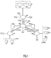
- a data transmission system comprises a plurality of nodes N1, N2, N3 and N4, the nodes N1 and N3, N2 and N3, and N3 and N4 being respectively interconnected by specialized links L2, L3 and L1.
- the system thus represented by way of example on this Figure 1 constitutes a banking network.
- the node N4 links to the network a server H from which several databases A and B are available for processing file transfer applications or transactional applications.
- This node N4 is furthermore provided with three accesses S1, S2 and S3 to a switched network provided for rescue in the event of a node or link failure.
- the node N3 has two accesses S4 and S5 to the said switched network, and it is directly connected to a money dispenser M3 and to an ATM G3.
- the nodes N2 and N1 are each provided with access S6 and respectively S7 to the said switched network. They each connect a local area network LAN1 and respectively LAN2 to which money dispensers M1 and respectively M2 are connected, and terminals for managing customer accounts T1 and respectively T2a and T2b.
- the network formed by the four nodes N1, N2, N3 and N4 is a network of type X25 and the switched switched network is a network of type ISDN.
- the invention is applicable to other types of networks (frame relay, switched telephone network, etc.)
- the data streams corresponding to file transfer applications and the data streams corresponding to transactional applications must be separated, so that each node can measure, for the communications for which it plays the role of source node, the load corresponding to file transfer applications.
- different addresses are assigned to the different applications whether or not they reside on the same machine. When the applications reside on different machines, their network address is by nature different. Otherwise, the network address common to the different applications must be distinguished at the application level.
- the calling and called addresses consist of at most 15 decimal digits. Networks generally do not use all of these locations to encode calling and called addresses. In an advantageous embodiment, the invention uses the remaining locations to code the addresses at the application level.
- the French Transpac network uses only 9 locations to code its addresses.
- node N4 is accessed via the Transpac network
- “123456789” being the address of node N4 on the Transpac network
- “10” being the number of the output link from node N4 to server H
- the address of file transfer applications is written for example 123456789-10-08, where "08" corresponds to the number of database A.
- the address of transactional applications is written 123456789-10-09 where "09" corresponds to the number of database B.
- three different virtual circuits CV1, CV2 and CV3 are respectively opened following a call from the distributor M2 to the database B to verify whether the card it is processing is part of from the stolen card file, and following a call from the terminals T2a and T2b to the database A to search among the customer files.
- These three virtual circuits physically transit on the same links, the L1 and L3 links.
- a virtual circuit CV4 is also established between the nodes N3 and N4 following a request for file transfer from the window G3 to the database A.
- a virtual circuit CV5 is established between nodes N1 and N4 following a file transfer request from terminal T1 to database A.
- each node is provided with means for measuring the overall load of the file transfer applications for which it plays the role of source node.
- virtual circuits of the same nature that is to say which correspond either to local file transfer traffic, or to remote file transfer traffic, or to transactional traffic
- destination of the same node are grouped together on the same virtual line according to the diagram shown in Figure 3, and the traffic measurement is done by virtual league.
- the link L3 which connects the nodes N2 and N3 is composed of two virtual lines LV1 and LV2 respectively dedicated to the transaction traffic corresponding to the virtual circuit CV1 and to the local file transfer traffic corresponding to the virtual circuits CV2 and CV3.
- the link L2 is composed of a single virtual line LV3 dedicated to the local file transfer traffic corresponding to the virtual circuit CV5.
- the link L1 is composed of three virtual lines LV4, LV5 and LV6 respectively dedicated to the transaction traffic corresponding to the virtual circuit CV1, to the remote file transfer traffic corresponding to the virtual circuits CV2, CV3 and CV5, and to the local transfer traffic of file corresponding to the virtual circuit CV4.
- the nodes N1, N2 and N3 therefore each monitor the load generated by the local file transfer traffic, that is to say the load on the virtual line LV3 for the node N1, on the virtual line LV2 for the node N2 and on the virtual line LV6 for the node N3.
- the time is shown on the abscissa and the line load as a percentage of the nominal speed of the link is plotted on the ordinate.
- the load is less than the low threshold P2.
- the load is between the low and high thresholds P2 and P1.
- the high threshold P1 is greater than the high threshold P1. The bottleneck of the line is thus detected two consecutive times, and it is therefore confirmed at time T5.
- the node When a crossing of the high threshold is confirmed, the node seeks to establish a switched connection with the recipient of the communication in order to switch all of the communications on this switched connection and to close the corresponding virtual circuits.
- a switched connection between the source node and the destination node of the packets is called an end-to-end link.
- both ends of the link i.e., the server and the remote user
- the node when a bottleneck is confirmed on the virtual LV2 league, the node establishes a faster switched connection (64kb / s for an ISDN B channel against 9600b / s for a dedicated link) with the destination node N4 via d one of the accesses S1, S2 or S3, then closes the virtual circuit CV2 so that all the capacity of the specialized link L3 remains available for the transactional application corresponding to the virtual line LV1.
- the node N2 re-establishes the virtual circuit CV2 towards the node N4 and closes the switched link.
- FIG. 4 represents a switch X25 according to the invention, denoted N.
- a switch comprises at least one network interface X25 denoted IX and an ISDN interface denoted IR which are connected to an application processor 10 constituted for example by a 68360 of Motorola.
- This processor 10 is itself connected by a bus 14 to a memory 11 for configuring the node.
- the processor 10 is also connected by this bus 14 to a static memory 12 which contains the operating instructions of the processor 10, in particular those necessary for the implementation of the invention, and to a random access memory 13 containing data, and in particular, for each link of the node, the different parameters necessary for calculating the load on this link, as well as said preconfigured routing table.
- the node N also has a local interface IL.
- this interface is connected to a communication controller 20, formed for example from an Intel 82503 transmitter and a controller Intel 82596DX.
- This communication controller 20 is itself connected by a bus 22 to a communication processor 23, constituted for example by a T400 from Inmos, to a static memory 21 containing the operating instructions of the communication processor 23, and to the memory of see above 13.
- the separation of the data streams and the measurement of the load on a link can be carried out by other methods than those described here by way of example.
Abstract
Description
La présente invention concerne un système de transmission de données comportant une pluralité de noeuds reliés entre eux par des liaisons pour établir des communications relatives au moins à des applications de transfert de fichier et à des applications transactionnelles, certains de ces noeuds étant dotés d'au moins un accès à un réseau commuté.The present invention relates to a data transmission system comprising a plurality of nodes linked together by links to establish communications relating to at least file transfer applications and transactional applications, some of these nodes being provided with minus access to a dial-up network.
L'invention a d'importantes applications notamment dans le domaine de l'interconnexion de réseaux locaux par l'intermédiaire de réseaux étendus de type X25 par exemple.The invention has important applications in particular in the field of interconnection of local networks by means of wide area networks of the X25 type for example.
En effet, l'utilisation de tels réseaux pour l'interconnexion de réseaux locaux modifie la nature des flux de données transportés par le réseau. Au trafic transactionnel classique s'ajoute alors un trafic de transfert de fichier. Le problème qui se pose alors est celui de l'écoulement de ces deux types de trafic sans surdimensionnement de la capacité des liaisons.The use of such networks for the interconnection of local networks changes the nature of the data flows carried by the network. In addition to traditional transaction traffic, file transfer traffic is added. The problem which then arises is that of the flow of these two types of traffic without oversizing the capacity of the links.
Pour cela, il est connu notamment du protocole multi-liaison défini dans la recommandation X25 du CCITT, d'utiliser une ou plusieurs liaisons d'un réseau commuté prévu habituellement pour le secours, afin de répartir l'ensemble du trafic d'une liaison momentanément engorgée. Cette méthode présente toutefois plusieurs inconvénients. D'une part, il s'agit d'un traitement local de l'engorgement qui devra donc être répété sur chaque tronçon de liaison entre le noeud source et le noeud destinataire. D'autre part, ce traitement porte sur l'ensemble du trafic et donc en particulier sur le trafic transactionnel. Or le fait de dérouter le trafic transactionnel a pour conséquence d'interrompre la communication pendant un court instant, et donc d'entraîner une gêne au niveau de l'utilisateur.For this, it is known in particular from the multi-link protocol defined in CCITT recommendation X25, to use one or more links of a switched network usually provided for back-up, in order to distribute all the traffic on a link momentarily engorged. However, this method has several drawbacks. On the one hand, it is a local processing of the congestion which will therefore have to be repeated on each link section between the source node and the destination node. On the other hand, this processing relates to all traffic and therefore in particular to transactional traffic. However, diverting transactional traffic has the consequence of interrupting communication for a short time, and therefore of causing discomfort at the level of the user.
L'invention a pour but de proposer un système de transmission de données qui remédie à ces inconvénients.The object of the invention is to propose a data transmission system which overcomes these drawbacks.
Pour cela un système de transmission de données selon l'invention et tel que défini dans le paragraphe introductif est caractérisé en ce que chacun de ces noeuds comporte:
- des moyens de séparation de flux pour établir des communications distinctes pour des applications de transfert de fichier et pour des applications transactionnelles,
- des moyens pour former un groupe d'au moins une communication correspondant à une application locale de transfert de fichier,
- des moyens de mesure de la charge générée par ledit groupe,
- des moyens pour basculer au moins partiellement ledit groupe sur le réseau commuté lorsque ladite charge est supérieure à un niveau dit niveau haut, et tant qu'elle reste supérieure à un niveau dit niveau bas.
- flow separation means for establishing separate communications for file transfer applications and for transactional applications,
- means for forming a group of at least one communication corresponding to a local file transfer application,
- means for measuring the load generated by said group,
- means for at least partially switching said group onto the switched network when said load is greater than a level known as high level, and as long as it remains greater than a level known as low level.
Dans un mode de réalisation particulièrement avantageux d'un système de transmission de données selon l'invention, pour basculer au moins partiellement ledit groupe sur le réseau commuté, chacun desdits noeuds comporte:
- des moyens pour établir une connexion de bout en bout entre les noeuds source et destinataire,
- fermer les communications correspondantes,
- rétablir lesdites communications sur le réseau commuté.
- means for establishing an end-to-end connection between the source and destination nodes,
- close the corresponding communications,
- re-establish said communications on the switched network.
L'invention concerne également un noeud, et plus particulièrement un commutateur X25, destiné à être utilisé dans un tel système.The invention also relates to a node, and more particularly to an X25 switch, intended for use in such a system.
D'autres particularités, détails et avantages de la présente invention apparaîtront dans la description qui va suivre en regard des dessins annexés qui sont donnés à titre d'exemple non limitatif et dans lesquels:
- la figure 1 représente schématiquement un exemple de système de transmission selon l'invention,
- la figure 2 est un graphique explicitant le principe utilisé pour mesurer la charge,
- la figure 3 représente sous une autre forme le système de transmission de la figure 1,
- la figure 4 représente un exemple de noeud selon l'invention.
- FIG. 1 schematically represents an example of a transmission system according to the invention,
- FIG. 2 is a graph explaining the principle used to measure the load,
- FIG. 3 represents in another form the transmission system of FIG. 1,
- FIG. 4 represents an example of a node according to the invention.
D'après la figure 1 un système de transmission de données selon l'invention comporte une pluralité de noeuds N1, N2, N3 et N4, les noeuds N1 et N3, N2 et N3, et N3 et N4 étant respectivement reliés entre eux par des liaisons spécialisées L2, L3 et L1. Le système ainsi représenté à titre d'exemple sur cette figure 1 constitue un réseau bancaire. Le noeud N4 relie au réseau un serveur H à partir duquel plusieurs bases de données A et B sont disponibles pour traiter des applications de transfert de fichier ou des applications transactionnelles. Ce noeud N4 est par ailleurs doté de trois accès S1, S2 et S3 à un réseau commuté prévu pour le secours en cas de panne d'un noeud ou d'une liaison. Le noeud N3 est doté de deux accès S4 et S5 au dit réseau commuté, et il est directement relié à un distributeur de monnaie M3 et à un guichet G3. Les noeuds N2 et N1 enfin sont chacun dotés d'un accès S6 et respectivement S7 au dit réseau commuté. Ils relient chacun un réseau local LAN1 et respectivement LAN2 sur lesquels sont connectés des distributeurs de monnaie M1 et respectivement M2, et des terminaux de gestion des comptes clients T1 et respectivement T2a et T2b.According to FIG. 1, a data transmission system according to the invention comprises a plurality of nodes N1, N2, N3 and N4, the nodes N1 and N3, N2 and N3, and N3 and N4 being respectively interconnected by specialized links L2, L3 and L1. The system thus represented by way of example on this Figure 1 constitutes a banking network. The node N4 links to the network a server H from which several databases A and B are available for processing file transfer applications or transactional applications. This node N4 is furthermore provided with three accesses S1, S2 and S3 to a switched network provided for rescue in the event of a node or link failure. The node N3 has two accesses S4 and S5 to the said switched network, and it is directly connected to a money dispenser M3 and to an ATM G3. Finally, the nodes N2 and N1 are each provided with access S6 and respectively S7 to the said switched network. They each connect a local area network LAN1 and respectively LAN2 to which money dispensers M1 and respectively M2 are connected, and terminals for managing customer accounts T1 and respectively T2a and T2b.
Dans cet exemple de réalisation le réseau formé par les quatre noeuds N1, N2, N3 et N4 est un réseau de type X25 et le réseau commuté de secours est un réseau de type RNIS. Toutefois l'invention est applicable à d'autres types de réseaux (Relais de trames, réseau téléphonique commuté...)In this exemplary embodiment, the network formed by the four nodes N1, N2, N3 and N4 is a network of type X25 and the switched switched network is a network of type ISDN. However, the invention is applicable to other types of networks (frame relay, switched telephone network, etc.)
Selon l'invention, les flux de données correspondant à des applications de transfert de fichier et les flux de données correspondant à des applications transactionnelles doivent être séparés, de telle sorte que chaque noeud puisse mesurer, pour les communications pour lesquelles il joue le rôle de noeud source, la charge correspondant aux applications de transfert de fichier. Pour cela des adresses différentes sont attribuées aux différentes applications qu'elles résident ou non sur une même machine. Lorsque les applications résident sur des machines différentes, leur adresse réseau est par nature différente. Dans le cas contraire, l'adresse réseau commune aux différentes applications doit être distinguée au niveau applicatif.According to the invention, the data streams corresponding to file transfer applications and the data streams corresponding to transactional applications must be separated, so that each node can measure, for the communications for which it plays the role of source node, the load corresponding to file transfer applications. For this, different addresses are assigned to the different applications whether or not they reside on the same machine. When the applications reside on different machines, their network address is by nature different. Otherwise, the network address common to the different applications must be distinguished at the application level.
Dans un réseau X25 les adresses appelantes et appelées se composent d'au plus 15 chiffres décimaux. Les réseaux n'utilisent en général pas la totalité de ces emplacements pour coder les adresses appelantes et appelées. Dans un mode de réalisation avantageux, l'invention utilise les emplacements restants pour coder les adresses au niveau applicatif.In an X25 network, the calling and called addresses consist of at most 15 decimal digits. Networks generally do not use all of these locations to encode calling and called addresses. In an advantageous embodiment, the invention uses the remaining locations to code the addresses at the application level.
A titre d'exemple, le réseau français Transpac n'utilise que 9 emplacements pour coder ses adresses. Dans le cas où l'on accède au noeud N4 par l'intermédiaire du réseau Transpac, "123456789" étant l'adresse du noeud N4 sur le réseau Transpac, et "10" étant le numéro de la liaison de sortie du noeud N4 vers le serveur H, l'adresse des applications de transfert de fichier (base de données A) s'écrit par exemple 123456789-10-08, où "08" correspond au numéro de la base de donnée A. Et, l'adresse des applications transactionnelles (base de données B) s'écrit 123456789-10-09 où "09" correspond au numéro de la base de données B.For example, the French Transpac network uses only 9 locations to code its addresses. In the case where node N4 is accessed via the Transpac network, "123456789" being the address of node N4 on the Transpac network, and "10" being the number of the output link from node N4 to server H, the address of file transfer applications (database A) is written for example 123456789-10-08, where "08" corresponds to the number of database A. And, the address of transactional applications (database B) is written 123456789-10-09 where "09" corresponds to the number of database B.
De même, dans le cas où l'ensemble des noeuds du système appartiennent à un réseau privé de numéro "2080" par exemple, si le numéro du noeud N4 sur ce réseau est "30", l'adresse des applications de transfert de fichier s'écrit 2080-30-10-08, et l'adresse des applications transactionnelles s'écrit 2080-30-10-09.Similarly, in the case where all the nodes of the system belong to a private network of number "2080" for example, if the number of node N4 on this network is "30", the address of file transfer applications is written 2080-30-10-08, and the address of transactional applications is written 2080-30-10-09.
Ainsi, en se reportant à la figure 1, trois circuits virtuels différents CV1, CV2 et CV3 sont respectivement ouverts suite à un appel du distributeur M2 vers la base de données B pour vérifier si la carte qu'il est en train de traiter fait partie du fichier des cartes volées, et suite à un appel des terminaux T2a et T2b vers la base de données A pour faire une recherche parmi les fichiers clients. Ces trois circuits virtuels transitent physiquement sur les mêmes liaisons, les liaisons L1 et L3.Thus, with reference to FIG. 1, three different virtual circuits CV1, CV2 and CV3 are respectively opened following a call from the distributor M2 to the database B to verify whether the card it is processing is part of from the stolen card file, and following a call from the terminals T2a and T2b to the database A to search among the customer files. These three virtual circuits physically transit on the same links, the L1 and L3 links.
De plus, toujours d'après la figure 1, un circuit virtuel CV4 est également établi entre les noeuds N3 et N4 suite à une demande de transfert de fichier du guichet G3 vers la base de données A. Et un circuit virtuel CV5 est établi entre les noeuds N1 et N4 suite à une demande de transfert de fichier du terminal T1 vers la base de données A.In addition, still according to FIG. 1, a virtual circuit CV4 is also established between the nodes N3 and N4 following a request for file transfer from the window G3 to the database A. And a virtual circuit CV5 is established between nodes N1 and N4 following a file transfer request from terminal T1 to database A.
Dans le mode de réalisation décrit par la suite, chaque noeud est doté de moyen de mesure de la charge globale des applications de transfert de fichier pour lesquelles il joue le rôle de noeud source. A cet effet, les circuits virtuels de même nature (c'est-à-dire qui correspondent soit à du trafic local de transfert de fichier, soit à du trafic distant de transfert de fichier, soit à du trafic transactionnel), et à destination d'un même noeud, sont regroupés sur une même ligne virtuelle conformément au schéma représenté figure 3, et la mesure de trafic se fait par ligue virtuelle.In the embodiment described below, each node is provided with means for measuring the overall load of the file transfer applications for which it plays the role of source node. For this purpose, virtual circuits of the same nature (that is to say which correspond either to local file transfer traffic, or to remote file transfer traffic, or to transactional traffic), and to destination of the same node, are grouped together on the same virtual line according to the diagram shown in Figure 3, and the traffic measurement is done by virtual league.
Dans un autre mode de réalisation il est toutefois possible de mettre en oeuvre une mesure de la charge individuelle des circuits virtuels pour lesquels le noeud joue le rôle de noeud source.In another embodiment, it is however possible to implement a measurement of the individual load of the virtual circuits for which the node plays the role of source node.
D'après la figure 3, la liaison L3 qui relie les noeuds N2 et N3 est composée de deux lignes virtuelles LV1 et LV2 respectivement dédiée au trafic transactionnel correspondant au circuit virtuel CV1 et au trafic local de transfert de fichier correspondant au circuits virtuels CV2 et CV3. La liaison L2 est composée d'une unique ligne virtuelle LV3 dédiée au trafic local de transfert de fichier correspondant au circuit virtuel CV5. Et la liaison L1 est composée de trois lignes virtuelles LV4, LV5 et LV6 respectivement dédiée au trafic transactionnel correspondant au circuit virtuel CV1, au trafic distant de transfert de fichier correspondant aux circuits virtuels CV2, CV3 et CV5, et au trafic local de transfert de fichier correspondant au circuit virtuel CV4.According to FIG. 3, the link L3 which connects the nodes N2 and N3 is composed of two virtual lines LV1 and LV2 respectively dedicated to the transaction traffic corresponding to the virtual circuit CV1 and to the local file transfer traffic corresponding to the virtual circuits CV2 and CV3. The link L2 is composed of a single virtual line LV3 dedicated to the local file transfer traffic corresponding to the virtual circuit CV5. And the link L1 is composed of three virtual lines LV4, LV5 and LV6 respectively dedicated to the transaction traffic corresponding to the virtual circuit CV1, to the remote file transfer traffic corresponding to the virtual circuits CV2, CV3 and CV5, and to the local transfer traffic of file corresponding to the virtual circuit CV4.
Les noeuds N1, N2 et N3 surveillent donc chacun la charge engendrée par le trafic local de transfert de fichier, c'est-à-dire la charge sur la ligne virtuelle LV3 pour le noeud N1, sur la ligne virtuelle LV2 pour le noeud N2 et sur la ligne virtuelle LV6 pour le noeud N3.The nodes N1, N2 and N3 therefore each monitor the load generated by the local file transfer traffic, that is to say the load on the virtual line LV3 for the node N1, on the virtual line LV2 for the node N2 and on the virtual line LV6 for the node N3.
La figure 2 représente un graphe qui explicite le mode de calcul d'une telle charge. Pour chaque liaison, un ensemble de paramètres est défini à cet effet:
- un premier paramètre P1 appelé seuil haut, correspondant à un premier pourcentage du débit nominal de la liaison (80% par exemple), et au delà duquel un engorgement est détecté,
- un second paramètre P2 appelé seuil bas, correspondant à un second pourcentage du débit nominal de la liaison (40% par exemple), et en deçà duquel un désengorgement est détecté,
- un troisième paramètre P3, défini pour l'ensemble des lignes virtuelles d'un noeud, et appelé temps d'intégration qui indique la durée sur laquelle le calcul est effectué, et qui est par exemple égal à 20 secondes,
- un quatrième paramètre P4 dit de consolidation qui indique combien de fois consécutives un dépassement de seuil haut ou bas doit être détecté pour être confirmé, et qui est par exemple égal à 2.
- a first parameter P1 called the high threshold, corresponding to a first percentage of the nominal flow of the link (80% for example), and beyond which a congestion is detected,
- a second parameter P2 called the low threshold, corresponding to a second percentage of the nominal speed of the link (40% for example), and below which a congestion is detected,
- a third parameter P3, defined for all of the virtual lines of a node, and called integration time which indicates the duration over which the calculation is carried out, and which is for example equal to 20 seconds,
- a fourth parameter P4 called consolidation which indicates how many times in succession a breach of a high or low threshold must be detected in order to be confirmed, and which is for example equal to 2.
Sur la figure 2, le temps est représenté en abscisse et la charge de la ligne en pourcentage du débit nominal de la liaison est porté en ordonnée. Entre les instants T1 et T2 distants de 20s la charge est inférieure au seuil bas P2. Entre les instants T2 et T3, la charge est comprise entre les seuils bas et haut P2 et P1. Entre les instants T3 et T4, puis entre les instants T4 et T5, elle est supérieure au seuil haut P1. L'engorgement de la ligne est ainsi détecté deux fois consécutives, et il est donc confirmé à l'instant T5.In FIG. 2, the time is shown on the abscissa and the line load as a percentage of the nominal speed of the link is plotted on the ordinate. Between times T1 and T2 20s apart, the load is less than the low threshold P2. Between times T2 and T3, the load is between the low and high thresholds P2 and P1. Between instants T3 and T4, then between instants T4 and T5, it is greater than the high threshold P1. The bottleneck of the line is thus detected two consecutive times, and it is therefore confirmed at time T5.
De même, entre les instants T1' et T2', puis entre les instants T2' et T3', la charge est comprise entre les seuils haut et bas P1 et P2. Et entre les instants T3' et T4', puis T4' et T5', la charge est inférieure au niveau bas P2. Le désengorgement étant ainsi détecté deux fois consécutives, il est confirmé à l'instant T5'.Similarly, between instants T1 'and T2', then between instants T2 'and T3', the load is between the high and low thresholds P1 and P2. And between times T3 'and T4', then T4 'and T5', the charge is lower than the low level P2. Decongestion being thus detected two consecutive times, it is confirmed at time T5 '.
Lorsqu'un franchissement du seuil haut est confirmé, le noeud cherche à établir une liaison commutée avec le destinataire de la communication afin de basculer l'ensemble des communications sur cette liaison commutée et de fermer les circuits virtuels correspondants. Une telle liaison commutée entre le noeud source et le noeud destinataire des paquets est qualifiée de liaison de bout en bout. Dans certains cas, lorsque les deux extrémités de la liaisons (c'est-à-dire le serveur et l'utilisateur distant) ne sont pas capable de rétablir eux-même les circuits virtuels sur la liaison commutée, ce sont les noeuds extrémités qui s'en chargent.When a crossing of the high threshold is confirmed, the node seeks to establish a switched connection with the recipient of the communication in order to switch all of the communications on this switched connection and to close the corresponding virtual circuits. Such a switched connection between the source node and the destination node of the packets is called an end-to-end link. In some cases, when both ends of the link (i.e., the server and the remote user) are unable to re-establish the virtual circuits on the dial-up themselves, it is the end nodes that take care of it.
Dans un autre mode de réalisation, il est également possible de ne basculer que certaines communications de la ligne virtuelle sur le réseau commuté.In another embodiment, it is also possible to switch only certain communications of the virtual line on the switched network.
De façon à effectuer ce basculement, chaque noeud est doté d'une table de routage préconfigurée qui associe les adresses des applications de transfert de fichier sur le réseau, les numéros des lignes virtuelles de sortie du noeud qui sont dédiées au trafic local de transfert de fichier correspondant, les numéros des accès commutés de secours utilisables à partir du noeud, et les adresses sur le réseau commuté du noeud destinataire. A titre d'exemple et en se référant à la figure 1, la table de routage préconfigurée du noeud N2 contient:
- l'adresse sur le réseau de l'applicatif de transfert de fichier, c'est-à-dire de la base de données A,
- le numéro de la ligue virtuelle LV2,
- le numéro S6 de l'accès au réseau commuté du noeud N2,
- et les adresses du noeud destinataire N4 sur le réseau commuté, c'est-à-dire les adresses sur le réseau commuté des accès S1, S2 et S3.
- the address on the network of the file transfer application, that is to say of database A,
- the number of the virtual league LV2,
- the number S6 of the access to the switched network of the node N2,
- and the addresses of the destination node N4 on the switched network, that is to say the addresses on the switched network of the ports S1, S2 and S3.
Ainsi, lorsqu'un engorgement est confirmé sur la ligue virtuelle LV2, le noeud établit une liaison commutée plus rapide (64kb/s pour un canal B RNIS contre 9600b/s pour un liaison spécialisée) avec le noeud destinataire N4 par l'intermédiaire d'un des accès S1, S2 ou S3, puis ferme le circuit virtuel CV2 de telle sorte que toute la capacité de la liaison spécialisé L3 reste disponible pour l'application transactionnelle correspondant à la ligne virtuelle LV1.Thus, when a bottleneck is confirmed on the virtual LV2 league, the node establishes a faster switched connection (64kb / s for an ISDN B channel against 9600b / s for a dedicated link) with the destination node N4 via d one of the accesses S1, S2 or S3, then closes the virtual circuit CV2 so that all the capacity of the specialized link L3 remains available for the transactional application corresponding to the virtual line LV1.
En revanche, dès qu'un désengorgement est confirmé sur cette liaison commutée, le noeud N2 rétablit le circuit virtuel CV2 vers le noeud N4 et ferme le liaison commutée.On the other hand, as soon as a congestion is confirmed on this switched link, the node N2 re-establishes the virtual circuit CV2 towards the node N4 and closes the switched link.
La figure 4 représente un commutateur X25 selon l'invention, noté N. Un tel commutateur comporte au moins une interface réseau X25 notée IX et une interface RNIS notée IR qui sont reliées à un processeur d'applications 10 constitué par exemple par un 68360 de Motorola. Ce processeur 10 est lui-même relié par un bus 14 à une mémoire 11 de configuration du noeud. Le processeur 10 est également relié par ce bus 14 à une mémoire statique 12 qui contient les instructions de fonctionnement du processeur 10, notamment celles nécessaires à la mise en oeuvre de l'invention, et à une mémoire vive 13 contenant des données, et en particulier, pour chaque liaison du noeud, les différents paramètres nécessaires au calcul de la charge sur cette liaison, ainsi que ladite table de routage préconfigurée. Le noeud N est également doté d'une interface locale IL. A titre d'exemple, pour un réseau local Ethernet, cette interface est reliée à un contrôleur de communication 20, formé par exemple à partir d'un transmetteur Intel 82503 et d'un contrôleur Intel 82596DX. Ce contrôleur de communication 20 est lui même relié par un bus 22 à un processeur de communication 23, constitué par exemple par un T400 de Inmos, à une mémoire statique 21 contenant les instructions de fonctionnement du processeur de communication 23, et à la mémoire de donnes 13 précitée.FIG. 4 represents a switch X25 according to the invention, denoted N. Such a switch comprises at least one network interface X25 denoted IX and an ISDN interface denoted IR which are connected to an
Il va de soi que des modifications peuvent être apportées au mode de réalisation qui vient d'être décrit, notamment par substitution de moyens techniques équivalents sans que l'on sorte pour cela du domaine de la présente invention.It goes without saying that modifications can be made to the embodiment which has just been described, in particular by substitution of equivalent technical means without departing from the scope of the present invention.
En particulier la séparation des flux de données et la mesure de la charge sur une liaison peuvent être réalisées selon d'autres méthodes que celles décrites ici à titre d'exemple.In particular, the separation of the data streams and the measurement of the load on a link can be carried out by other methods than those described here by way of example.
Claims (6)
caractérisé en ce que chacun de ces noeuds comporte:
characterized in that each of these nodes comprises:
Applications Claiming Priority (2)
| Application Number | Priority Date | Filing Date | Title |
|---|---|---|---|
| FR9410724 | 1994-09-07 | ||
| FR9410724 | 1994-09-07 |
Publications (1)
| Publication Number | Publication Date |
|---|---|
| EP0701349A1 true EP0701349A1 (en) | 1996-03-13 |
Family
ID=9466766
Family Applications (1)
| Application Number | Title | Priority Date | Filing Date |
|---|---|---|---|
| EP95202378A Withdrawn EP0701349A1 (en) | 1994-09-07 | 1995-09-04 | Data transmission system and node with congestion monitoring |
Country Status (3)
| Country | Link |
|---|---|
| US (1) | US5729528A (en) |
| EP (1) | EP0701349A1 (en) |
| JP (1) | JPH0888644A (en) |
Cited By (1)
| Publication number | Priority date | Publication date | Assignee | Title |
|---|---|---|---|---|
| EP0801479A1 (en) * | 1995-12-29 | 1997-10-15 | AT&T Corp. | Data network security system and method |
Families Citing this family (19)
| Publication number | Priority date | Publication date | Assignee | Title |
|---|---|---|---|---|
| US6038219A (en) * | 1996-12-31 | 2000-03-14 | Paradyne Corporation | User-configurable frame relay network |
| US6151327A (en) * | 1997-06-30 | 2000-11-21 | Mci Communications Corporation | Method of routing and bundling demands with low utilization in a telecommunications network |
| US6453352B1 (en) * | 1997-07-14 | 2002-09-17 | Electronic Data Systems Corporation | Integrated electronic commerce system and method |
| US6079034A (en) * | 1997-12-05 | 2000-06-20 | Hewlett-Packard Company | Hub-embedded system for automated network fault detection and isolation |
| US6826620B1 (en) * | 1998-08-26 | 2004-11-30 | Paradyne Corporation | Network congestion control system and method |
| US7756032B2 (en) * | 2000-10-17 | 2010-07-13 | Avaya Inc. | Method and apparatus for communicating data within measurement traffic |
| US7406539B2 (en) * | 2000-10-17 | 2008-07-29 | Avaya Technology Corp. | Method and apparatus for performance and cost optimization in an internetwork |
| US7363367B2 (en) * | 2000-10-17 | 2008-04-22 | Avaya Technology Corp. | Systems and methods for robust, real-time measurement of network performance |
| US8023421B2 (en) * | 2002-07-25 | 2011-09-20 | Avaya Inc. | Method and apparatus for the assessment and optimization of network traffic |
| US7487237B2 (en) * | 2000-10-17 | 2009-02-03 | Avaya Technology Corp. | Load optimization |
| DE60141417D1 (en) | 2000-10-17 | 2010-04-08 | Avaya Technology Corp | METHOD AND DEVICE FOR OPTIMIZING PERFORMANCE AND COST IN AN INTERNET PLANT |
| US7336613B2 (en) * | 2000-10-17 | 2008-02-26 | Avaya Technology Corp. | Method and apparatus for the assessment and optimization of network traffic |
| US7349994B2 (en) | 2000-10-17 | 2008-03-25 | Avaya Technology Corp. | Method and apparatus for coordinating routing parameters via a back-channel communication medium |
| US7720959B2 (en) * | 2000-10-17 | 2010-05-18 | Avaya Inc. | Method and apparatus for characterizing the quality of a network path |
| US20020129099A1 (en) * | 2001-03-08 | 2002-09-12 | International Business Machines Corporation | Method and apparatus for virtualizing a serial port in a data processing system |
| US7230924B2 (en) * | 2001-03-28 | 2007-06-12 | At&T Corp. | Method and apparatus for communications traffic engineering |
| US20030058860A1 (en) * | 2001-09-25 | 2003-03-27 | Kunze Aaron R. | Destination address filtering |
| US20030158942A1 (en) * | 2002-02-15 | 2003-08-21 | Exanet, Inc. | Real-time reconfiguration of computer networks based on system measurements |
| EP1790131B1 (en) * | 2004-09-09 | 2012-12-05 | Avaya Inc. | Methods of and systems for network traffic security |
Citations (2)
| Publication number | Priority date | Publication date | Assignee | Title |
|---|---|---|---|---|
| WO1990012466A1 (en) * | 1989-04-10 | 1990-10-18 | Bell Communications Research, Inc. | A technique for dynamically changing an isdn connection during a host session |
| EP0465090A1 (en) * | 1990-07-03 | 1992-01-08 | AT&T Corp. | Congestion control for connectionless traffic in data networks via alternate routing |
-
1995
- 1995-09-04 EP EP95202378A patent/EP0701349A1/en not_active Withdrawn
- 1995-09-06 US US08/523,832 patent/US5729528A/en not_active Expired - Fee Related
- 1995-09-07 JP JP7230441A patent/JPH0888644A/en active Pending
Patent Citations (2)
| Publication number | Priority date | Publication date | Assignee | Title |
|---|---|---|---|---|
| WO1990012466A1 (en) * | 1989-04-10 | 1990-10-18 | Bell Communications Research, Inc. | A technique for dynamically changing an isdn connection during a host session |
| EP0465090A1 (en) * | 1990-07-03 | 1992-01-08 | AT&T Corp. | Congestion control for connectionless traffic in data networks via alternate routing |
Non-Patent Citations (1)
| Title |
|---|
| R.KRISHNA THILAKAM ET AL: "THE DESIGN AND FLOW CONTROL OF A HIGH SPEED, INTEGRATED, PACKET SWITCHED NETWORK", COMPUTER NETWORKS AND ISDN SYSTEMS, vol. 25, no. 3, September 1992 (1992-09-01), AMSTERDAM NL, pages 241 - 257, XP000298712 * |
Cited By (2)
| Publication number | Priority date | Publication date | Assignee | Title |
|---|---|---|---|---|
| EP0801479A1 (en) * | 1995-12-29 | 1997-10-15 | AT&T Corp. | Data network security system and method |
| US6252869B1 (en) | 1995-12-29 | 2001-06-26 | At&T Corp. | Data network security system and method |
Also Published As
| Publication number | Publication date |
|---|---|
| JPH0888644A (en) | 1996-04-02 |
| US5729528A (en) | 1998-03-17 |
Similar Documents
| Publication | Publication Date | Title |
|---|---|---|
| EP0701349A1 (en) | Data transmission system and node with congestion monitoring | |
| JP3388512B2 (en) | Managing routing in packet communication networks | |
| US5692126A (en) | ISDN access to fast packet data network | |
| EP1507384B1 (en) | Method of masking the processing of an access request to a server and corresponding system | |
| JPH06509689A (en) | How to reroute connections | |
| FR2849731A1 (en) | Failure detection method for communication link, involves sending probe packet and setting probe timer when predetermined time interval set by timer expires | |
| FR2753323A1 (en) | Internet router for LAN switching hub | |
| EP1168719B1 (en) | Distributed Virtual Router with Redundancy for Networks with Changing Topology | |
| BE1004912A4 (en) | INTERNAL ROUTING PROCESS FOR LOAD BALANCING. | |
| EP0688121A1 (en) | System for interconnection of local area networks and apparatus for use in such a system | |
| EP1788760A1 (en) | System and method for static packet data flow routing in an interconnection network | |
| EP0701353A1 (en) | Data transmission system with adaptive routing | |
| EP0692891A1 (en) | System and equipment for the interconnection of LAN's using a source routing protocol | |
| EP1575240A1 (en) | Device and method for a treatment of frames with multiprotocol usage field for a communication network | |
| FR2811180A1 (en) | IP DATA TRANSMISSION NETWORK USING ROUTE SELECTION SYSTEM BASED ON LEVEL 4/5 INFORMATION | |
| FR2704999A1 (en) | TELECOMMUNICATIONS NETWORK OF ENDS FOR THE TRANSMISSION OF DATA BY PACKAGES. | |
| WO2004056049A1 (en) | Dual-ring ethernet network | |
| US6243380B1 (en) | Method and apparatus for mapping asynchronous ports to HDLC addresses | |
| US8675667B1 (en) | Systems and methods for forming and operating robust communication networks for an enterprise | |
| EP0169757A1 (en) | Method of determining the last intermediate node in a network of several interconnected nodes | |
| FR2625858A1 (en) | METHOD AND DEVICE FOR SWITCHING A DATA PACKET | |
| FR3085567B1 (en) | COMMUNICATION NETWORK ON BOARD OF A VEHICLE, SUBSCRIBER EQUIPMENT OF SUCH COMMUNICATION NETWORK AND CORRESPONDING PROCEDURE | |
| Cisco | Features | |
| FR3063858A1 (en) | COMMUNICATION METHOD FOR MAINTAINING AN APPLICATION SESSION BETWEEN TERMINAL AND APPLICATION SERVER | |
| EP0967830A1 (en) | Signalling data transmission method |
Legal Events
| Date | Code | Title | Description |
|---|---|---|---|
| PUAI | Public reference made under article 153(3) epc to a published international application that has entered the european phase |
Free format text: ORIGINAL CODE: 0009012 |
|
| AK | Designated contracting states |
Kind code of ref document: A1 Designated state(s): DE FR GB IT |
|
| RAP1 | Party data changed (applicant data changed or rights of an application transferred) |
Owner name: PHILIPS ELECTRONICS N.V. Owner name: PHILIPS COMMUNICATION D'ENTREPRISE |
|
| 17P | Request for examination filed |
Effective date: 19960913 |
|
| RAP1 | Party data changed (applicant data changed or rights of an application transferred) |
Owner name: COMPAGNIE DES SIGNAUX Owner name: PCE |
|
| STAA | Information on the status of an ep patent application or granted ep patent |
Free format text: STATUS: THE APPLICATION HAS BEEN WITHDRAWN |
|
| 18W | Application withdrawn |
Withdrawal date: 19991206 |