EP0692911A2 - Method of splicing MPEG encoded video - Google Patents
Method of splicing MPEG encoded video Download PDFInfo
- Publication number
- EP0692911A2 EP0692911A2 EP95110995A EP95110995A EP0692911A2 EP 0692911 A2 EP0692911 A2 EP 0692911A2 EP 95110995 A EP95110995 A EP 95110995A EP 95110995 A EP95110995 A EP 95110995A EP 0692911 A2 EP0692911 A2 EP 0692911A2
- Authority
- EP
- European Patent Office
- Prior art keywords
- data
- buffer
- data stream
- sequence
- bits
- Prior art date
- Legal status (The legal status is an assumption and is not a legal conclusion. Google has not performed a legal analysis and makes no representation as to the accuracy of the status listed.)
- Granted
Links
Images


Classifications
-
- H—ELECTRICITY
- H04—ELECTRIC COMMUNICATION TECHNIQUE
- H04N—PICTORIAL COMMUNICATION, e.g. TELEVISION
- H04N21/00—Selective content distribution, e.g. interactive television or video on demand [VOD]
- H04N21/20—Servers specifically adapted for the distribution of content, e.g. VOD servers; Operations thereof
- H04N21/23—Processing of content or additional data; Elementary server operations; Server middleware
- H04N21/236—Assembling of a multiplex stream, e.g. transport stream, by combining a video stream with other content or additional data, e.g. inserting a URL [Uniform Resource Locator] into a video stream, multiplexing software data into a video stream; Remultiplexing of multiplex streams; Insertion of stuffing bits into the multiplex stream, e.g. to obtain a constant bit-rate; Assembling of a packetised elementary stream
- H04N21/23611—Insertion of stuffing data into a multiplex stream, e.g. to obtain a constant bitrate
-
- G—PHYSICS
- G11—INFORMATION STORAGE
- G11B—INFORMATION STORAGE BASED ON RELATIVE MOVEMENT BETWEEN RECORD CARRIER AND TRANSDUCER
- G11B27/00—Editing; Indexing; Addressing; Timing or synchronising; Monitoring; Measuring tape travel
- G11B27/02—Editing, e.g. varying the order of information signals recorded on, or reproduced from, record carriers
- G11B27/031—Electronic editing of digitised analogue information signals, e.g. audio or video signals
- G11B27/036—Insert-editing
-
- H—ELECTRICITY
- H04—ELECTRIC COMMUNICATION TECHNIQUE
- H04N—PICTORIAL COMMUNICATION, e.g. TELEVISION
- H04N19/00—Methods or arrangements for coding, decoding, compressing or decompressing digital video signals
- H04N19/10—Methods or arrangements for coding, decoding, compressing or decompressing digital video signals using adaptive coding
- H04N19/102—Methods or arrangements for coding, decoding, compressing or decompressing digital video signals using adaptive coding characterised by the element, parameter or selection affected or controlled by the adaptive coding
- H04N19/132—Sampling, masking or truncation of coding units, e.g. adaptive resampling, frame skipping, frame interpolation or high-frequency transform coefficient masking
-
- H—ELECTRICITY
- H04—ELECTRIC COMMUNICATION TECHNIQUE
- H04N—PICTORIAL COMMUNICATION, e.g. TELEVISION
- H04N19/00—Methods or arrangements for coding, decoding, compressing or decompressing digital video signals
- H04N19/10—Methods or arrangements for coding, decoding, compressing or decompressing digital video signals using adaptive coding
- H04N19/134—Methods or arrangements for coding, decoding, compressing or decompressing digital video signals using adaptive coding characterised by the element, parameter or criterion affecting or controlling the adaptive coding
- H04N19/142—Detection of scene cut or scene change
-
- H—ELECTRICITY
- H04—ELECTRIC COMMUNICATION TECHNIQUE
- H04N—PICTORIAL COMMUNICATION, e.g. TELEVISION
- H04N19/00—Methods or arrangements for coding, decoding, compressing or decompressing digital video signals
- H04N19/10—Methods or arrangements for coding, decoding, compressing or decompressing digital video signals using adaptive coding
- H04N19/134—Methods or arrangements for coding, decoding, compressing or decompressing digital video signals using adaptive coding characterised by the element, parameter or criterion affecting or controlling the adaptive coding
- H04N19/146—Data rate or code amount at the encoder output
- H04N19/152—Data rate or code amount at the encoder output by measuring the fullness of the transmission buffer
-
- H—ELECTRICITY
- H04—ELECTRIC COMMUNICATION TECHNIQUE
- H04N—PICTORIAL COMMUNICATION, e.g. TELEVISION
- H04N19/00—Methods or arrangements for coding, decoding, compressing or decompressing digital video signals
- H04N19/10—Methods or arrangements for coding, decoding, compressing or decompressing digital video signals using adaptive coding
- H04N19/134—Methods or arrangements for coding, decoding, compressing or decompressing digital video signals using adaptive coding characterised by the element, parameter or criterion affecting or controlling the adaptive coding
- H04N19/162—User input
-
- H—ELECTRICITY
- H04—ELECTRIC COMMUNICATION TECHNIQUE
- H04N—PICTORIAL COMMUNICATION, e.g. TELEVISION
- H04N19/00—Methods or arrangements for coding, decoding, compressing or decompressing digital video signals
- H04N19/10—Methods or arrangements for coding, decoding, compressing or decompressing digital video signals using adaptive coding
- H04N19/169—Methods or arrangements for coding, decoding, compressing or decompressing digital video signals using adaptive coding characterised by the coding unit, i.e. the structural portion or semantic portion of the video signal being the object or the subject of the adaptive coding
- H04N19/17—Methods or arrangements for coding, decoding, compressing or decompressing digital video signals using adaptive coding characterised by the coding unit, i.e. the structural portion or semantic portion of the video signal being the object or the subject of the adaptive coding the unit being an image region, e.g. an object
- H04N19/172—Methods or arrangements for coding, decoding, compressing or decompressing digital video signals using adaptive coding characterised by the coding unit, i.e. the structural portion or semantic portion of the video signal being the object or the subject of the adaptive coding the unit being an image region, e.g. an object the region being a picture, frame or field
-
- H—ELECTRICITY
- H04—ELECTRIC COMMUNICATION TECHNIQUE
- H04N—PICTORIAL COMMUNICATION, e.g. TELEVISION
- H04N19/00—Methods or arrangements for coding, decoding, compressing or decompressing digital video signals
- H04N19/10—Methods or arrangements for coding, decoding, compressing or decompressing digital video signals using adaptive coding
- H04N19/169—Methods or arrangements for coding, decoding, compressing or decompressing digital video signals using adaptive coding characterised by the coding unit, i.e. the structural portion or semantic portion of the video signal being the object or the subject of the adaptive coding
- H04N19/186—Methods or arrangements for coding, decoding, compressing or decompressing digital video signals using adaptive coding characterised by the coding unit, i.e. the structural portion or semantic portion of the video signal being the object or the subject of the adaptive coding the unit being a colour or a chrominance component
-
- H—ELECTRICITY
- H04—ELECTRIC COMMUNICATION TECHNIQUE
- H04N—PICTORIAL COMMUNICATION, e.g. TELEVISION
- H04N19/00—Methods or arrangements for coding, decoding, compressing or decompressing digital video signals
- H04N19/60—Methods or arrangements for coding, decoding, compressing or decompressing digital video signals using transform coding
- H04N19/61—Methods or arrangements for coding, decoding, compressing or decompressing digital video signals using transform coding in combination with predictive coding
-
- H—ELECTRICITY
- H04—ELECTRIC COMMUNICATION TECHNIQUE
- H04N—PICTORIAL COMMUNICATION, e.g. TELEVISION
- H04N21/00—Selective content distribution, e.g. interactive television or video on demand [VOD]
- H04N21/20—Servers specifically adapted for the distribution of content, e.g. VOD servers; Operations thereof
- H04N21/23—Processing of content or additional data; Elementary server operations; Server middleware
- H04N21/234—Processing of video elementary streams, e.g. splicing of video streams, manipulating MPEG-4 scene graphs
- H04N21/23424—Processing of video elementary streams, e.g. splicing of video streams, manipulating MPEG-4 scene graphs involving splicing one content stream with another content stream, e.g. for inserting or substituting an advertisement
-
- H—ELECTRICITY
- H04—ELECTRIC COMMUNICATION TECHNIQUE
- H04N—PICTORIAL COMMUNICATION, e.g. TELEVISION
- H04N19/00—Methods or arrangements for coding, decoding, compressing or decompressing digital video signals
- H04N19/10—Methods or arrangements for coding, decoding, compressing or decompressing digital video signals using adaptive coding
- H04N19/134—Methods or arrangements for coding, decoding, compressing or decompressing digital video signals using adaptive coding characterised by the element, parameter or criterion affecting or controlling the adaptive coding
- H04N19/146—Data rate or code amount at the encoder output
-
- H—ELECTRICITY
- H04—ELECTRIC COMMUNICATION TECHNIQUE
- H04N—PICTORIAL COMMUNICATION, e.g. TELEVISION
- H04N19/00—Methods or arrangements for coding, decoding, compressing or decompressing digital video signals
- H04N19/50—Methods or arrangements for coding, decoding, compressing or decompressing digital video signals using predictive coding
Definitions
- This invention concerns the processing of video signals encoded according to the standard adopted by the Moving Picture Experts Group (MPEG) and in particular, a method of splicing an MPEG encoded data stream from a first source to an MPEG encoded data stream from a second source in a manner that ensures that no video data is lost when the combined image is reproduced.
- MPEG Moving Picture Experts Group
- the MPEG-2 standard is actually several different standards. In MPEG-2 several different profiles are defined, each corresponding to a different level of complexity of the encoded image. For each profile, different levels are defined, each level corresponding to a different image resolution.
- One of the MPEG-2 "standards”, known as Main Profile, Main Level is intended for encoding video signals conforming to existing television standards (i.e., NTSC and PAL).
- Another "standard”, known as Main Profile, High Level is intended for encoding high-definition television images. Images encoded according to the Main Profile, High Level standard may have as many as 1,152 active lines per image frame and 1,920 pixels per line. It is this standard which is currently being implemented as the United States HDTV standard.
- the MPEG-2 standard defines a complex syntax which contains a mixture of data and control information. Some of this control information is used to enable the signals having several different formats to be covered by the standard. These formats define images, having differing numbers of picture elements (pixels) per line, differing numbers of lines per frame or field and differing numbers of frames or fields per second.
- the basic syntax of the MPEG-2 Main Profile defines the compressed MPEG-2 bit stream representing a sequence of images in six layers, the sequence layer, the group pictures layer, the picture layer, the slice layer, the macro block layer, and the block layer. Each of these layers is introduced with control information and "stuffing" characters. The stuffing characters are inserted as needed to ensure that the data rate of the input data stream matches the rate at which pictures are displayed.
- other control information also known as side information, (e.g. frame type, macroblock pattern, image motion vectors, coefficient zig-zag patterns and dequantization information) are interspersed throughout the coded bit stream.
- VBV buffer size specifies a number of bits of input data from the video sequence which must be stored in the input buffer of the decoder before the video sequence may be decoded. If this number of bits is stored when the decoding operation begins, the input buffer will neither become too full (overflow) or become empty (underflow) during the processing of the video sequence.
- the VBV buffer size value assumes that the input buffer is empty when the new sequence data is received or, at least that all of the data in the input buffer will be removed before the contents of the input buffer reach the VBV buffer size value. To ensure that the VBV buffer size value does not cause the input buffer to overflow or underflow, it is preferred in the MPEG standard that any image splicing be done on a sequence boundary.
- the data already resident in the input buffer may not be read from the buffer for processing until the buffer overflows due to the new data from the inserted sequence.
- the data already resident in the input buffer may cause the decoder to prematurely indicate that the VBV buffer size criterion has been met.
- the decoder may cause the input buffer to either overflow or underflow in the processing of the stored data.
- Another method would be to define a format within the MPEG standard which allows for easy insertion and provide a flag identifying this format. This method, however, cannot handle incompatible formats and reduces the robustness of the MPEG standard.
- the present invention is embodied in a method of processing a main MPEG encoded sequence to allow another sequence to be inserted at any picture boundary in the main sequence.
- the main and inserted MPEG sequences are analyzed to determine a number of stuffing characters to insert in the data stream after the selected picture boundary and before the inserted sequence.
- the stuffing characters are ignored during the decoding operation and allow the input buffer to be emptied to a level compatible with the inserted sequence.
- This number stuffing characters is determined from the data rates of the main and inserted sequences and the intervals between respective points in time corresponding to the start of the insertion and the next decoding time stamps in both the main and inserted sequences.
- the method inserts this number of stuffing characters after the selected splice point and then inserts the inserted sequence.
- Figure 1 is a data diagram which illustrates an insertion operation according to the present invention.
- Figures 2a and 2b are graphs of buffer fullness versus time which are useful for explaining the operation of the present invention for fixed data rate MPEG-2 encoded signals.
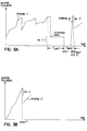
- Figures 3a and 3b are graphs of buffer fullness versus time which are useful for explaining the operation of the present invention for variable data rate MPEG-2 encoded signals.
- FIG. 4 is a block diagram of circuitry suitable for use in an HDTV or MPEG-2 encoder and decoder which operates in accordance with the present invention.
- Figure 5 is a flow-chart diagram of a process which extracts parameter values from the main and inserted data stream.
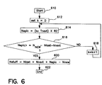
- Figure 6 is a flow-chart diagram of a process which calculates a number of stuffing bits to be inserted from the extracted parameters.
- Figure 7 is a flow-chart diagram of an insertion process which inserts the number of stuffing bits calculated in Figure 6 between the insertion point between in main sequence and the start of the inserted sequence.
- Figures 7a, 7b and 7c are graphs of buffer fullness versus time which are useful for explaining the operation of the present invention when the variable k, in Figure 7, has a value of one.
- Figure 1 is a data diagram which illustrates the splicing operation.
- a sequence 112 is inserted into a sequence 110 of the main HDTV signal to form a modified sequence 110'.
- the main MPEG sequence 110 includes a sequence header 112, including a sequence start code, several access units (pictures) 116 and a sequence end code 114.
- the group of pictures layer which is between the sequence layer and the picture layer is not shown in Figure 1.
- the sequence to be inserted, 112 also includes a sequence header 118, several access units 122 and a sequence end code 120.
- each sequence start code may be preceded by a string of zero-valued stuffing bits.
- these bits represent null information which is ignored by the decoder and is not written into the input buffer.
- the stuffing bits are used to ensure that the rate at which data is being supplied matches the rate at which images, derived from the data, are being displayed. While these stuffing bits are being received, the decoder is reading data from the input buffer for display. Thus, the amount of data held in the input buffer is reduced while the stuffing bits are being received.
- the combined sequences are shown as the modified data stream 110' of Figure 1.
- This data stream includes the sequence header 112, access units 116, a modified sequence header 118' access units 122 and a modified sequence end code 120'.
- the modified sequence start code 118' includes a sequence end code, which marks the end of the first part of the previous main sequence, a number, NSTUFF, of stuffing bits, the sequence start code for the inserted sequence and the modified header for the inserted sequence.
- the bit-rate field of the original header for the inserted sequence is modified to be FFFF hexadecimal, indicating a variable bit-rate sequence. This change is made only if the bit rate of the inserted sequence is different from that of the main sequence and the original inserted sequence was a constant bit-rate sequence.
- the method according to the present invention splices the start of one sequence to an arbitrary access unit in another sequence.
- the insertion of the sequence is completed only after the remaining part of the original sequence is spliced to the inserted sequence in the same way that the inserted sequence was spliced to the main sequence.
- the modified sequence header 120' also includes a sequence end code, some stuffing bits and the modified sequence header for the main sequence.
- the sequence header 120' may have its bit-rate field changed to FFFF hexadecimal, indicating a variable bit-rate sequence, if the bit-rates of the main and inserted sequences differ and if the original main sequence used a constant bit-rate.
- the number of stuffing bits to be added is determined by the method of the subject invention as described below with reference to Figures 5 and 6.
- the actual splicing operation is performed as described below with reference to Figures 2, 3 and 7.
- Figures 2a and 2b are graphs of buffer fullness versus time which illustrate the problem addressed by the present invention and the method by which the problem is solved.
- the solid line in Figure 2a shows part of the data stream for the main sequence, STREAM1
- the solid line in Figure 2b shows part of the data stream for the inserted sequence, STREAM2.
- these data streams are bit-streams.
- Vertical transitions in these Figures indicate times at which data is being read from the buffer. It is a convention in these types of diagrams that data is modeled as being read from the buffer instantaneously. Portions of the curve which have slanted lines indicate times at which data is being written into the buffer. The slope of these lines is proportional to the data rate of the data stream.
- the sequence STREAM2 is to be inserted into the sequence STREAM1 at time T I , immediately after access unit AU1. If the maximum input buffer size used by this example is 1000 then, if STREAM2 were inserted into STREAM1 at time T I , then the buffer would overflow before the VBV buffer size (i.e. 500) for STREAM2 had been reached. To prevent this from occurring, the method according to the present invention inserts a number, NSTUFF, of stuffing bits between the AU1 at time T I and the start of STREAM2. This is indicated by the dashed line in Figure 2a. Thus, after T I , instead of following the solid line, the buffer fullness for the MPEG bit stream follows the dashed line.
- T last , DTS1, T next , DTS next and DTS2 are used, as described below to calculate the optimal value for NSTUFF. While the stuffing bits are being inserted into the data stream, no new data is added to the buffer. New data, representing the inserted sequence is added when the slope of the dashed line is non-zero.
- the rate at which data is provided by STREAM2 is less than the rate at which it is provided by STREAM1. Nonetheless, the first portion of the data of STREAM2, provided between the decoding time stamps DTS1 to DTS next , is provided at the same rate as the sequence STREAM1 while the portion of STREAM2 which is provided after DTS next is provided at the same rate as the original STREAM2, shown in Figure 2b.
- FIGs 2a and 2b illustrate the operation of an exemplary embodiment of the inventive method when the sequences are encoded to have a fixed data rate.
- Figures 3a and 3b illustrate the operation of the method when the sequences are encoded to have a variable data rate. Items in these Figures which correspond to items in Figures 2a and 2b are indicated by a prime mark (').
- FIG. 4 is a block diagram showing portions of an MPEG-2 or HDTV splicer and an MPEG-2 or HDTV decoder according to the present invention.
- the splicer includes a processor 412, which is coupled to receive the main and insert MPEG-2 HDTV signals, STREAM1 and STREAM2, respectively.
- Each of these signals may be generated by a conventional HDTV encoder, such as is described in U.S. Patent No. 5,294,974 entitled, HIGH DEFINITION VIDEO ENCODING SYSTEM HAVING COLOR-SENSITIVE QUANTIZATION, which is hereby incorporated by reference for its teaching on HDTV encoders.
- these signals may be generated by an MPEG-2 encoder such as that described in ISO/IEC 13818-2 DIS, which is hereby incorporated by reference for its teachings on MPEG-2 encoders.
- the processor 412 is coupled to two buffers, BStest 414 and BSdec 416. These buffers are preferably identical.
- the buffer 414 is used to gather information from which the value NSTUFF is calculated.
- the actual splicing is performed using the buffer 416.
- the spliced signal is then transmitted from buffer 416 to the input buffer 424 of the decoder 420.
- the decoder 420 also includes a processor 422 which retrieves data from the input buffer 424 in order to reproduce a moving image.
- FIG. 5 is a flow-chart diagram which illustrates the process that controls the processor 412 in gathering information about the sequences STREAM1 and STREAM2.
- This process begins at step 510.
- the processor initializes the buffer 414 by setting its write address pointer to the beginning of the buffer.
- the processor sends STREAM1 to the buffer at the data rate specified in the sequence header for STREAM1.
- both STREAM1 and STREAM2 are stored signals (e.g. recovered from digital video tape recorders).
- the signals may be accessed twice, once to determine splicing parameters and again to perform the actual splicing operation.
- a compensating delay (not shown) may be needed so that the splicing parameters may be determined before the actual splicing operation occurs.
- the process determines if the insertion point, immediately after the picture represented by access unit AU1 has been stored into the buffer 414. Until AU1 is received, every access unit that is received, is removed from the buffer 414 at the time indicated by the decoding time stamp (DTS) field of the access unit. In other words, the data is removed from the buffer 414 in the same sequence and with the same timing that it would be removed from an input buffer by a decoder, such as the decoder 420 shown in Figure 4. Even when each access unit is removed, the sequence STREAM1 continues to be provided at its proper data rate, as indicated by step 520, and control is transferred to step 516 to determine if AU1 has been received.
- DTS decoding time stamp
- T last is the difference in time between when AU1 was received and DTS1, the decoding time stamp for AU1, the time at which AU1 is to be read from the input buffer for processing.
- DTS next is the time to the next decoder time stamp after DTS1.
- the decoder time stamps occur at regular intervals. Accordingly, DTS next may be determined by calculating the difference between DTS1 and the preceding decoder time stamp and then adding this difference to DTS1. Alternatively, this value may be determined by monitoring STREAM1, extracting the DTS values from the access unit headers which follow AU1 until a DTS other than DTS1 is encountered. As shown in Figure 2a, T next is calculated by subtracting DTS1 from DTS next .
- N next the number of bits of data which will be stored into the buffer during the time interval T next , is calculated by multiplying T next by the data rate, R1, of STREAM1 or by any rate which is less than or equal to the maximum data stream rate, Rmax[p.1], as defined in ISO/IEC 13818-1 and ISO/IEC 13818-2.
- R1 is any data rate which is less than or equal to the maximum data rate for the data stream, R max [p.1], as defined in ISO/IEC 13818-1 and ISO/IEC 13818-2.
- the process again empties the buffer 414 and, at step 528, begins storing data from STREAM2 into buffer 414.
- This data is stored into the buffer at the bit rate of STREAM2.
- the data is stored until a time corresponding to the decoder time stamp for the first access unit of STREAM2. This time is designated DTS2*.
- the amount of data stored in buffer 414 at DTS2* is designated as N new and this value is saved by the process at step 534.
- the process determines whether STREAM2 is a fixed rate stream or a variable rate stream.
- step 538 determines a value R2, representing the bit rate of STREAM2.
- R2 is assigned the average value of the data rates over the time interval defined by DTS2*.
- the processor 412 calculates the value NSTUFF. This process starts at step 610 of Figure 6. At step 612, a temporary variable K is set to zero. Next, step 614 calculates a value N splc , representing an amount of data which is to be written into the buffer having the data rate R2.
- the amount of data represented by N new may not be able to be stored into the buffer, at the data rate R1, during the time interval T next .
- This situation is handled by the loop which includes the steps 614, 616 and 618.
- a trial value for N splc is determined as the product of K, T next and R2.
- this trial value is compared to the quantity N new minus N last minus N next .
- N splc is greater than or equal to N new minus N last minus N next at step 616, then control is transferred to step 620 to determine the value of NSTUFF according to equation (1).
- NSTUFF N last + N next + N splc - N new
- step 622 the process ends.
- the inventors have determined that if this number of stuffing bits are added before the inserted sequence STREAM2, there will be no overflow of the input buffer when the data stream is received.
- the processor 412 executes the process shown in Figure 7 to splice STREAM2 to STREAM1.
- This process begins at step 710 by emptying the buffer BSdec, 416, shown in Figure 4.
- the processor 412 sends data from STREAM1 into buffer 416 at the data rate of STREAM1.
- the process determines if the last bit of AU1 has been written into buffer 416. If not, the process continues to provide data from STREAM1 until AU1 has been stored as indicated by steps 716 and 718, removing any AU's prior to AU1 at intervals corresponding to their decoder time stamps (DTS's).
- DTS's decoder time stamps
- the process After AU1 has been stored, the process, at step 720 removes any AU's in the buffer 416 which precede and include AU1 at the corresponding decoding time stamp of each AU. Starting from the time that AU1 has been stored, the process, at step 722 sends NSTUFF stuffing bits to buffer 416 at the bit rate R1. At step 724, the process determines if all NSTUFF of the stuffing bits were sent before the time DTS next . If not, control transfers to step 734 which determines if all NSTUFF of the stuffing bits were sent at the time DTS next . If this condition is not met, step 736 is executed to send the remaining stuffing bits at rate R2 to buffer 416.
- step 726 is executed which begins sending the initial part of STREAM2 to buffer 416 at bit-rate R1.
- step 728 the process determines if the variable K has a value of zero. If not, control transfers to step 738 in which data from STREAM2 is sent to buffer 416 at the bit-rate R2. Step 738 is also executed after step 734 if it is determined that NSTUFF bits have been sent at time DTS next and after step 736. After step 738, step 740 is executed which removes AU2 from buffer 416 at a time corresponding to DTS2.
- Figures 7a, 7b and 7c are graphs of buffer fullness versus time which show a splice in which K has a value of one.
- the bit rate is R2
- the bit rate of STREAM2 if STREAM2 is a constant bit-rate sequence, and it is the average bit-rate during T2* (shown in Figure 7b) if STREAM2 is a variable bit-rate sequence.
- step 730 first access unit of STREAM2, AU2, is removed from buffer.
- step 732 is executed which continues to provide data from STREAM2, at the bit-rate of STREAM2. This is the last step of the splicing process.
- data is removed from buffer 416 and applied to the input buffer 424 of the decoder 420.
- the buffer 424 ignores the stuffing bits, effectively delaying the application of the STREAM2 data until sufficient data has been removed from the input buffer 424, by the processor 422, to make room for the STREAM2 data.
Abstract
Description
- This invention concerns the processing of video signals encoded according to the standard adopted by the Moving Picture Experts Group (MPEG) and in particular, a method of splicing an MPEG encoded data stream from a first source to an MPEG encoded data stream from a second source in a manner that ensures that no video data is lost when the combined image is reproduced.
- In the United States a standard has been proposed for digitally encoded high definition television signals. This standard is essentially the same as the MPEG-2 standard, proposed by the Moving Picture Experts Group (MPEG) of the International Standards Organization (ISO). This standard is described in a draft international standard (DIS) publication entitled "Information Technology - Generic Coding of Moving Pictures and Associated Audio, Recommendation H.262" which is available from the ISO and which is hereby incorporated by reference for its teaching on the MPEG-2 systems standard "ISO/IEC 13818-1" and for its teachings on the MPEG-2 digital video encoding standard "ISO/IEC 13818-2."
- The MPEG-2 standard is actually several different standards. In MPEG-2 several different profiles are defined, each corresponding to a different level of complexity of the encoded image. For each profile, different levels are defined, each level corresponding to a different image resolution. One of the MPEG-2 "standards", known as Main Profile, Main Level is intended for encoding video signals conforming to existing television standards (i.e., NTSC and PAL). Another "standard", known as Main Profile, High Level is intended for encoding high-definition television images. Images encoded according to the Main Profile, High Level standard may have as many as 1,152 active lines per image frame and 1,920 pixels per line. It is this standard which is currently being implemented as the United States HDTV standard.
- The MPEG-2 standard defines a complex syntax which contains a mixture of data and control information. Some of this control information is used to enable the signals having several different formats to be covered by the standard. These formats define images, having differing numbers of picture elements (pixels) per line, differing numbers of lines per frame or field and differing numbers of frames or fields per second. In addition, the basic syntax of the MPEG-2 Main Profile defines the compressed MPEG-2 bit stream representing a sequence of images in six layers, the sequence layer, the group pictures layer, the picture layer, the slice layer, the macro block layer, and the block layer. Each of these layers is introduced with control information and "stuffing" characters. The stuffing characters are inserted as needed to ensure that the data rate of the input data stream matches the rate at which pictures are displayed. Finally, other control information, also known as side information, (e.g. frame type, macroblock pattern, image motion vectors, coefficient zig-zag patterns and dequantization information) are interspersed throughout the coded bit stream.
- To effectively receive the digital images, a decoder must recognize the control portions, extract the necessary control information, and use the extracted data to process the video signal information. One piece of information that is specified for each sequence layer is the video buffering verifier (VBV) buffer size. The VBV buffer size value specifies a number of bits of input data from the video sequence which must be stored in the input buffer of the decoder before the video sequence may be decoded. If this number of bits is stored when the decoding operation begins, the input buffer will neither become too full (overflow) or become empty (underflow) during the processing of the video sequence.
- The VBV buffer size value assumes that the input buffer is empty when the new sequence data is received or, at least that all of the data in the input buffer will be removed before the contents of the input buffer reach the VBV buffer size value. To ensure that the VBV buffer size value does not cause the input buffer to overflow or underflow, it is preferred in the MPEG standard that any image splicing be done on a sequence boundary.
- This may be unacceptable, however, for video editors who would like to switch from one scene to another after a particular picture has been displayed, irrespective of whether that picture is at a sequence boundary. It may also be undesirable for broadcasters who wish to insert short program segments, for example station identification messages or advertisements into an HDTV program at arbitrary intervals.
- If splicing is not done at a sequence boundary then the data already resident in the input buffer may not be read from the buffer for processing until the buffer overflows due to the new data from the inserted sequence. Alternatively, the data already resident in the input buffer may cause the decoder to prematurely indicate that the VBV buffer size criterion has been met. In this instance, the decoder may cause the input buffer to either overflow or underflow in the processing of the stored data.
- One method of solving this problem is proposed in the MPEG-2 standard DIS ISO/IEC 13818-1. By this method, certain access units, or pictures, in the data stream are marked with a SEAMLESS_SPLICE_FLAG. This flag is used to mark safe locations for splicing an inserted sequence into the main sequence. As with the conventional splicing method, however, there are only a limited number of access units which satisfy the criteria to have this flag set. Furthermore, this splicing method limits the bit rate of the inserted stream to a certain level to meet its criteria and the inserted stream can not be a variable bit rate stream.
- Another method would be to define a format within the MPEG standard which allows for easy insertion and provide a flag identifying this format. This method, however, cannot handle incompatible formats and reduces the robustness of the MPEG standard.
- The present invention is embodied in a method of processing a main MPEG encoded sequence to allow another sequence to be inserted at any picture boundary in the main sequence. According to the present invention, the main and inserted MPEG sequences are analyzed to determine a number of stuffing characters to insert in the data stream after the selected picture boundary and before the inserted sequence. The stuffing characters are ignored during the decoding operation and allow the input buffer to be emptied to a level compatible with the inserted sequence. This number stuffing characters is determined from the data rates of the main and inserted sequences and the intervals between respective points in time corresponding to the start of the insertion and the next decoding time stamps in both the main and inserted sequences. The method inserts this number of stuffing characters after the selected splice point and then inserts the inserted sequence.
- Figure 1 is a data diagram which illustrates an insertion operation according to the present invention.
- Figures 2a and 2b are graphs of buffer fullness versus time which are useful for explaining the operation of the present invention for fixed data rate MPEG-2 encoded signals.
- Figures 3a and 3b are graphs of buffer fullness versus time which are useful for explaining the operation of the present invention for variable data rate MPEG-2 encoded signals.
- Figure 4 is a block diagram of circuitry suitable for use in an HDTV or MPEG-2 encoder and decoder which operates in accordance with the present invention.
- Figure 5 is a flow-chart diagram of a process which extracts parameter values from the main and inserted data stream.
- Figure 6 is a flow-chart diagram of a process which calculates a number of stuffing bits to be inserted from the extracted parameters.
- Figure 7 is a flow-chart diagram of an insertion process which inserts the number of stuffing bits calculated in Figure 6 between the insertion point between in main sequence and the start of the inserted sequence.
- Figures 7a, 7b and 7c are graphs of buffer fullness versus time which are useful for explaining the operation of the present invention when the variable k, in Figure 7, has a value of one.
- Figure 1 is a data diagram which illustrates the splicing operation. In this figures, a
sequence 112 is inserted into asequence 110 of the main HDTV signal to form a modified sequence 110'. As shown in Figure 1, themain MPEG sequence 110 includes asequence header 112, including a sequence start code, several access units (pictures) 116 and asequence end code 114. For the sake of simplicity, the group of pictures layer, which is between the sequence layer and the picture layer is not shown in Figure 1. The sequence to be inserted, 112, also includes asequence header 118,several access units 122 and asequence end code 120. - As defined in the MPEG standard, each sequence start code may be preceded by a string of zero-valued stuffing bits. In the MPEG standard, these bits represent null information which is ignored by the decoder and is not written into the input buffer. The stuffing bits are used to ensure that the rate at which data is being supplied matches the rate at which images, derived from the data, are being displayed. While these stuffing bits are being received, the decoder is reading data from the input buffer for display. Thus, the amount of data held in the input buffer is reduced while the stuffing bits are being received.
- The combined sequences are shown as the modified data stream 110' of Figure 1. This data stream includes the
sequence header 112,access units 116, a modified sequence header 118' access units 122 and a modified sequence end code 120'. The modified sequence start code 118' includes a sequence end code, which marks the end of the first part of the previous main sequence, a number, NSTUFF, of stuffing bits, the sequence start code for the inserted sequence and the modified header for the inserted sequence. The bit-rate field of the original header for the inserted sequence is modified to be FFFF hexadecimal, indicating a variable bit-rate sequence. This change is made only if the bit rate of the inserted sequence is different from that of the main sequence and the original inserted sequence was a constant bit-rate sequence. - The method according to the present invention splices the start of one sequence to an arbitrary access unit in another sequence. The insertion of the sequence is completed only after the remaining part of the original sequence is spliced to the inserted sequence in the same way that the inserted sequence was spliced to the main sequence. Thus, the modified sequence header 120' also includes a sequence end code, some stuffing bits and the modified sequence header for the main sequence. As with the modified sequence header 118', the sequence header 120' may have its bit-rate field changed to FFFF hexadecimal, indicating a variable bit-rate sequence, if the bit-rates of the main and inserted sequences differ and if the original main sequence used a constant bit-rate.
- The number of stuffing bits to be added is determined by the method of the subject invention as described below with reference to Figures 5 and 6. The actual splicing operation is performed as described below with reference to Figures 2, 3 and 7.
- Figures 2a and 2b are graphs of buffer fullness versus time which illustrate the problem addressed by the present invention and the method by which the problem is solved. The solid line in Figure 2a shows part of the data stream for the main sequence, STREAM1, while the solid line in Figure 2b shows part of the data stream for the inserted sequence, STREAM2. In the exemplary embodiments of the invention, these data streams are bit-streams. Vertical transitions in these Figures indicate times at which data is being read from the buffer. It is a convention in these types of diagrams that data is modeled as being read from the buffer instantaneously. Portions of the curve which have slanted lines indicate times at which data is being written into the buffer. The slope of these lines is proportional to the data rate of the data stream.
- The sequence STREAM2 is to be inserted into the sequence STREAM1 at time TI, immediately after access unit AU1. If the maximum input buffer size used by this example is 1000 then, if STREAM2 were inserted into STREAM1 at time TI, then the buffer would overflow before the VBV buffer size (i.e. 500) for STREAM2 had been reached. To prevent this from occurring, the method according to the present invention inserts a number, NSTUFF, of stuffing bits between the AU1 at time TI and the start of STREAM2. This is indicated by the dashed line in Figure 2a. Thus, after TI, instead of following the solid line, the buffer fullness for the MPEG bit stream follows the dashed line. The values Tlast, DTS1, Tnext, DTSnext and DTS2 are used, as described below to calculate the optimal value for NSTUFF. While the stuffing bits are being inserted into the data stream, no new data is added to the buffer. New data, representing the inserted sequence is added when the slope of the dashed line is non-zero.
- It is noted, from Figures 2a and 2b that the rate at which data is provided by STREAM2 is less than the rate at which it is provided by STREAM1. Nonetheless, the first portion of the data of STREAM2, provided between the decoding time stamps DTS1 to DTSnext, is provided at the same rate as the sequence STREAM1 while the portion of STREAM2 which is provided after DTSnext is provided at the same rate as the original STREAM2, shown in Figure 2b.
- The graphs in Figures 2a and 2b illustrate the operation of an exemplary embodiment of the inventive method when the sequences are encoded to have a fixed data rate. Figures 3a and 3b illustrate the operation of the method when the sequences are encoded to have a variable data rate. Items in these Figures which correspond to items in Figures 2a and 2b are indicated by a prime mark (').
- Figure 4 is a block diagram showing portions of an MPEG-2 or HDTV splicer and an MPEG-2 or HDTV decoder according to the present invention. The splicer includes a
processor 412, which is coupled to receive the main and insert MPEG-2 HDTV signals, STREAM1 and STREAM2, respectively. Each of these signals may be generated by a conventional HDTV encoder, such as is described in U.S. Patent No. 5,294,974 entitled, HIGH DEFINITION VIDEO ENCODING SYSTEM HAVING COLOR-SENSITIVE QUANTIZATION, which is hereby incorporated by reference for its teaching on HDTV encoders. Alternatively, these signals may be generated by an MPEG-2 encoder such as that described in ISO/IEC 13818-2 DIS, which is hereby incorporated by reference for its teachings on MPEG-2 encoders. - The
processor 412 is coupled to two buffers,BStest 414 andBSdec 416. These buffers are preferably identical. Thebuffer 414 is used to gather information from which the value NSTUFF is calculated. The actual splicing is performed using thebuffer 416. The spliced signal is then transmitted frombuffer 416 to theinput buffer 424 of thedecoder 420. Thedecoder 420 also includes aprocessor 422 which retrieves data from theinput buffer 424 in order to reproduce a moving image. - Figure 5 is a flow-chart diagram which illustrates the process that controls the
processor 412 in gathering information about the sequences STREAM1 and STREAM2. This process begins atstep 510. Atstep 512, the processor initializes thebuffer 414 by setting its write address pointer to the beginning of the buffer. Atstep 514, the processor sends STREAM1 to the buffer at the data rate specified in the sequence header for STREAM1. It is noted that in the exemplary embodiment of the invention, both STREAM1 and STREAM2 are stored signals (e.g. recovered from digital video tape recorders). Thus, the signals may be accessed twice, once to determine splicing parameters and again to perform the actual splicing operation. For splicing two signals which are not stored but come, for example, from a satellite feed, a compensating delay (not shown) may be needed so that the splicing parameters may be determined before the actual splicing operation occurs. - At
step 514, the process determines if the insertion point, immediately after the picture represented by access unit AU1 has been stored into thebuffer 414. Until AU1 is received, every access unit that is received, is removed from thebuffer 414 at the time indicated by the decoding time stamp (DTS) field of the access unit. In other words, the data is removed from thebuffer 414 in the same sequence and with the same timing that it would be removed from an input buffer by a decoder, such as thedecoder 420 shown in Figure 4. Even when each access unit is removed, the sequence STREAM1 continues to be provided at its proper data rate, as indicated bystep 520, and control is transferred to step 516 to determine if AU1 has been received. - Once access unit AU1 has been received, control transfers to step 522 to determine values for Tlast and Nlast. As shown in Figure 2a, Tlast is the difference in time between when AU1 was received and DTS1, the decoding time stamp for AU1, the time at which AU1 is to be read from the input buffer for processing.
- Next, at
step 524, the process determines values for DTSnext, Tnext, and Nnext. DTSnext is the time to the next decoder time stamp after DTS1. In the MPEG standard, the decoder time stamps occur at regular intervals. Accordingly, DTSnext may be determined by calculating the difference between DTS1 and the preceding decoder time stamp and then adding this difference to DTS1. Alternatively, this value may be determined by monitoring STREAM1, extracting the DTS values from the access unit headers which follow AU1 until a DTS other than DTS1 is encountered. As shown in Figure 2a, Tnext is calculated by subtracting DTS1 from DTSnext. Likewise, Nnext, the number of bits of data which will be stored into the buffer during the time interval Tnext, is calculated by multiplying Tnext by the data rate, R1, of STREAM1 or by any rate which is less than or equal to the maximum data stream rate, Rmax[p.1], as defined in ISO/IEC 13818-1 and ISO/IEC 13818-2. This data rate is available from the sequence header. If STREAM1 is a variable rate data stream, as shown in Figure 3a, R1 is any data rate which is less than or equal to the maximum data rate for the data stream, Rmax [p.1], as defined in ISO/IEC 13818-1 and ISO/IEC 13818-2. - At
step 526, once these values have been determined, the process again empties thebuffer 414 and, atstep 528, begins storing data from STREAM2 intobuffer 414. This data is stored into the buffer at the bit rate of STREAM2. As shown by theloop including step 532, the data is stored until a time corresponding to the decoder time stamp for the first access unit of STREAM2. This time is designated DTS2*. The amount of data stored inbuffer 414 at DTS2* is designated as Nnew and this value is saved by the process atstep 534. Atstep 536, the process determines whether STREAM2 is a fixed rate stream or a variable rate stream. If it is a variable rate stream, control is transferred to step 538 to determine a value R2, representing the bit rate of STREAM2. In this instance, R2 is assigned the average value of the data rates over the time interval defined by DTS2*. Atstep 540, the process of collecting the parameters ends. - After the parameters have been determined, the
processor 412 calculates the value NSTUFF. This process starts atstep 610 of Figure 6. Atstep 612, a temporary variable K is set to zero. Next,step 614 calculates a value Nsplc, representing an amount of data which is to be written into the buffer having the data rate R2. - In some splices, the amount of data represented by Nnew may not be able to be stored into the buffer, at the data rate R1, during the time interval Tnext. This situation is handled by the loop which includes the
steps step 614, a trial value for Nsplc is determined as the product of K, Tnext and R2. Atstep 616, this trial value is compared to the quantity Nnew minus Nlast minus Nnext. - If, however, Nsplc is greater than or equal to Nnew minus Nlast minus Nnext at
step 616, then control is transferred to step 620 to determine the value of NSTUFF according to equation (1).
- At
step 622, the process ends. The inventors have determined that if this number of stuffing bits are added before the inserted sequence STREAM2, there will be no overflow of the input buffer when the data stream is received. - After a suitable value of NSTUFF has been determined, the
processor 412 executes the process shown in Figure 7 to splice STREAM2 to STREAM1. This process begins atstep 710 by emptying the buffer BSdec, 416, shown in Figure 4. Atstep 712, theprocessor 412 sends data from STREAM1 intobuffer 416 at the data rate of STREAM1. Atstep 714, the process determines if the last bit of AU1 has been written intobuffer 416. If not, the process continues to provide data from STREAM1 until AU1 has been stored as indicated bysteps - After AU1 has been stored, the process, at
step 720 removes any AU's in thebuffer 416 which precede and include AU1 at the corresponding decoding time stamp of each AU. Starting from the time that AU1 has been stored, the process, atstep 722 sends NSTUFF stuffing bits to buffer 416 at the bit rate R1. Atstep 724, the process determines if all NSTUFF of the stuffing bits were sent before the time DTSnext. If not, control transfers to step 734 which determines if all NSTUFF of the stuffing bits were sent at the time DTSnext. If this condition is not met,step 736 is executed to send the remaining stuffing bits at rate R2 to buffer 416. - If, however, at
step 724, it was determined that the NSTUFF stuffing bits had been sent before DTSnext,step 726 is executed which begins sending the initial part of STREAM2 to buffer 416 at bit-rate R1. Atstep 728, the process determines if the variable K has a value of zero. If not, control transfers to step 738 in which data from STREAM2 is sent to buffer 416 at the bit-rate R2. Step 738 is also executed afterstep 734 if it is determined that NSTUFF bits have been sent at time DTSnext and afterstep 736. Afterstep 738,step 740 is executed which removes AU2 frombuffer 416 at a time corresponding to DTS2. - Figures 7a, 7b and 7c are graphs of buffer fullness versus time which show a splice in which K has a value of one. In Figure 7c, it is noted that between the time indicated by DTSnext and the time indicated by DTS2, the bit rate is R2, the bit rate of STREAM2, if STREAM2 is a constant bit-rate sequence, and it is the average bit-rate during T2* (shown in Figure 7b) if STREAM2 is a variable bit-rate sequence.
- If, however, at
step 728, it is determined that the variable K is equal to zero, then atstep 730, first access unit of STREAM2, AU2, is removed from buffer. Afterstep 730 or step 740,step 732 is executed which continues to provide data from STREAM2, at the bit-rate of STREAM2. This is the last step of the splicing process. - As shown in Figure 4, data is removed from
buffer 416 and applied to theinput buffer 424 of thedecoder 420. Thebuffer 424 ignores the stuffing bits, effectively delaying the application of the STREAM2 data until sufficient data has been removed from theinput buffer 424, by theprocessor 422, to make room for the STREAM2 data. - While the invention has been described in terms of an exemplary embodiment, it is contemplated that it may be practiced as described above in accordance with the following claims.
Claims (4)
- A method of splicing a first and second data streams representing respective first and second encoded high-definition television signals at a selected picture boundary in the first data stream using a buffer, wherein each of the first and second data streams has a data rate and a plurality of decoding time stamps representing times at which data is retrieved from the buffer, the method comprising the steps of:
analyzing the first data stream to determine an amount of null information to be inserted in the first data stream after the selected picture boundary, wherein The amount of null data is determined from the data rates of the first and second data streams and the decoding time stamps in the first and second data streams;
transmitting the first data stream, up to the selected picture boundary to the buffer;
transmitting the determined amount of null information to the buffer;
transmitting the second data stream to the buffer; and
retrieving the spliced data stream from the buffer. - A method according to claim 1, wherein the step of transmitting the second data stream to the buffer includes the steps of:
transmitting a first portion of the second data stream to the buffer at the data rate of the first data stream; and
transmitting a second portion of the second data stream to the buffer at the data rate of the second data stream. - A method according to claim 2, wherein the data streams are bit-streams encoded according to a standard developed by the motion-picture experts group (MPEG) and the amount of null information is a number of stuffing bits to be inserted before a sequence start code of the second data stream.
- A method according to claim 3, wherein the amount of null information is determined by the equation:

Applications Claiming Priority (2)
| Application Number | Priority Date | Filing Date | Title |
|---|---|---|---|
| US27651594A | 1994-07-15 | 1994-07-15 | |
| US276515 | 1994-07-15 |
Publications (3)
| Publication Number | Publication Date |
|---|---|
| EP0692911A2 true EP0692911A2 (en) | 1996-01-17 |
| EP0692911A3 EP0692911A3 (en) | 1996-03-13 |
| EP0692911B1 EP0692911B1 (en) | 2000-03-08 |
Family
ID=23056938
Family Applications (1)
| Application Number | Title | Priority Date | Filing Date |
|---|---|---|---|
| EP19950110995 Expired - Lifetime EP0692911B1 (en) | 1994-07-15 | 1995-07-13 | Method of splicing MPEG encoded video |
Country Status (3)
| Country | Link |
|---|---|
| EP (1) | EP0692911B1 (en) |
| JP (1) | JP3091393B2 (en) |
| DE (1) | DE69515386T2 (en) |
Cited By (28)
| Publication number | Priority date | Publication date | Assignee | Title |
|---|---|---|---|---|
| EP0735777A2 (en) * | 1995-03-27 | 1996-10-02 | Sony Corporation | Cue-adaptive video encoding method and apparatus |
| EP0755157A2 (en) * | 1995-07-21 | 1997-01-22 | Matsushita Electric Industrial Co., Ltd. | Method of splicing MPEG encoded video |
| EP0805601A2 (en) * | 1996-05-02 | 1997-11-05 | Sony Corporation | Encoding, storing and transmitting digital signals |
| EP0708566A3 (en) * | 1994-10-21 | 1997-12-17 | AT&T Corp. | Method for controlling a video data encoder buffer |
| EP0837609A2 (en) * | 1996-10-18 | 1998-04-22 | Nextlevel Systems, Inc. | Splicing compressed packetized digital video streams |
| WO1998027734A1 (en) * | 1996-12-18 | 1998-06-25 | Thomson Consumer Electronics, Inc. | Efficient fixed-length block compression and decompression |
| WO1998032284A1 (en) * | 1997-01-17 | 1998-07-23 | Nds Limited | Improvements in or relating to switching between compressed bitstreams |
| WO1998044737A1 (en) * | 1997-03-28 | 1998-10-08 | Koninklijke Philips Electronics N.V. | Method for seamless splicing in a video encoder |
| WO1998054910A2 (en) * | 1997-05-27 | 1998-12-03 | Koninklijke Philips Electronics N.V. | Method of switching video sequences and corresponding switching device and decoding system |
| WO1999003280A1 (en) * | 1997-07-11 | 1999-01-21 | France Telecom | Data signal for modifying a graphic scene, corresponding method and device |
| GB2328099A (en) * | 1997-08-08 | 1999-02-10 | British Broadcasting Corp | Processing coded video particularly MPEG format video |
| WO1999008448A1 (en) * | 1997-08-06 | 1999-02-18 | Nds Limited | A method and apparatus for switching between digital bitstreams |
| GB2328826A (en) * | 1997-08-27 | 1999-03-03 | Mitsubishi Elec Sys Lsi Design | Picture coding method |
| WO1999027713A2 (en) * | 1997-11-25 | 1999-06-03 | Koninklijke Philips Electronics N.V. | Video buffer for seamless splicing of mpeg streams |
| WO1999030503A2 (en) * | 1997-12-09 | 1999-06-17 | Koninklijke Philips Electronics N.V. | Method and apparatus for encoding and slicing digital video bit streams |
| WO1999040728A1 (en) * | 1998-02-03 | 1999-08-12 | Koninklijke Philips Electronics N.V. | Method of switching of coded video sequences and corresponding device |
| WO1999040727A2 (en) * | 1998-02-03 | 1999-08-12 | Koninklijke Philips Electronics N.V. | Method of switching of coded video sequences and corresponding device |
| EP1037467A1 (en) * | 1999-03-08 | 2000-09-20 | Tandberg Television ASA | Real-time switching of digital signals without glitches |
| GB2353652A (en) * | 1999-08-26 | 2001-02-28 | Sony Uk Ltd | Video coding employing a predetermined percentage of stuffing bits |
| EP1130595A1 (en) * | 1998-11-25 | 2001-09-05 | Matsushita Electric Industrial Co., Ltd. | Stream editing apparatus and stream editing method |
| US6370199B1 (en) | 1998-04-03 | 2002-04-09 | Tandberg Television Asa | Method and apparatus for processing compressed video data streams |
| SG93179A1 (en) * | 1996-06-27 | 2002-12-17 | At & T Corp | Method for altering a broadcast transmission as a function of its recipient on a communications network |
| EP1217842A3 (en) * | 2000-12-21 | 2005-04-06 | General Instrument Corporation | Frame bit-size allocation for seamlessly spliced, variable-rate compressed digital video signals |
| US7010492B1 (en) | 1999-09-30 | 2006-03-07 | International Business Machines Corporation | Method and apparatus for dynamic distribution of controlled and additional selective overlays in a streaming media |
| KR100607382B1 (en) * | 1998-01-19 | 2006-08-02 | 소니 가부시끼 가이샤 | Compressed picture data editing apparatus and method |
| US7145912B1 (en) * | 2000-03-23 | 2006-12-05 | Tut Systems, Inc. | Demultiplexing a statistically multiplexed MPEG transport stream into CBR single program transport streams |
| CN100423509C (en) * | 2001-10-22 | 2008-10-01 | 松下电器产业株式会社 | Data flow selection output device, control program, data flow selection output method |
| US8341662B1 (en) | 1999-09-30 | 2012-12-25 | International Business Machine Corporation | User-controlled selective overlay in a streaming media |
Families Citing this family (2)
| Publication number | Priority date | Publication date | Assignee | Title |
|---|---|---|---|---|
| DE69838869T2 (en) * | 1997-10-03 | 2008-12-04 | Sony Corp. | Device and method for splicing coded data streams and device and method for generating coded data streams |
| WO2008146214A1 (en) * | 2007-05-29 | 2008-12-04 | Koninklijke Philips Electronics N.V. | Visualizing objects of a video signal |
Citations (1)
| Publication number | Priority date | Publication date | Assignee | Title |
|---|---|---|---|---|
| US5294974A (en) | 1992-07-24 | 1994-03-15 | Matsushita Electric Corporation Of America | High-definition video encoding system having color-sensitive quantization |
Family Cites Families (2)
| Publication number | Priority date | Publication date | Assignee | Title |
|---|---|---|---|---|
| JP2969782B2 (en) * | 1990-05-09 | 1999-11-02 | ソニー株式会社 | Encoded data editing method and encoded data editing device |
| US5367341A (en) * | 1992-10-20 | 1994-11-22 | Canon Information Systems, Inc. | Digital video editor having lost video frame protection |
-
1995
- 1995-07-13 EP EP19950110995 patent/EP0692911B1/en not_active Expired - Lifetime
- 1995-07-13 DE DE1995615386 patent/DE69515386T2/en not_active Expired - Fee Related
- 1995-07-14 JP JP17923495A patent/JP3091393B2/en not_active Expired - Fee Related
Patent Citations (1)
| Publication number | Priority date | Publication date | Assignee | Title |
|---|---|---|---|---|
| US5294974A (en) | 1992-07-24 | 1994-03-15 | Matsushita Electric Corporation Of America | High-definition video encoding system having color-sensitive quantization |
Cited By (47)
| Publication number | Priority date | Publication date | Assignee | Title |
|---|---|---|---|---|
| EP0708566A3 (en) * | 1994-10-21 | 1997-12-17 | AT&T Corp. | Method for controlling a video data encoder buffer |
| EP0735777A3 (en) * | 1995-03-27 | 1999-04-28 | Sony Corporation | Cue-adaptive video encoding method and apparatus |
| EP0735777A2 (en) * | 1995-03-27 | 1996-10-02 | Sony Corporation | Cue-adaptive video encoding method and apparatus |
| EP0755157A2 (en) * | 1995-07-21 | 1997-01-22 | Matsushita Electric Industrial Co., Ltd. | Method of splicing MPEG encoded video |
| EP0755157A3 (en) * | 1995-07-21 | 1997-09-17 | Matsushita Electric Ind Co Ltd | Method of splicing MPEG encoded video |
| US5949792A (en) * | 1996-05-02 | 1999-09-07 | Sony Corporation | Method and apparatus for encoding a digital signal, recording medium used for storing the digital signal, and method and apparatus for transmitting the digital signal |
| EP0805601A2 (en) * | 1996-05-02 | 1997-11-05 | Sony Corporation | Encoding, storing and transmitting digital signals |
| KR100476135B1 (en) * | 1996-05-02 | 2005-08-10 | 소니 가부시끼 가이샤 | Digital signal encoding method and apparatus, digital signal transmission method, recording medium |
| EP0805601A3 (en) * | 1996-05-02 | 1998-07-01 | Sony Corporation | Encoding, storing and transmitting digital signals |
| SG93179A1 (en) * | 1996-06-27 | 2002-12-17 | At & T Corp | Method for altering a broadcast transmission as a function of its recipient on a communications network |
| EP1463330A1 (en) * | 1996-10-18 | 2004-09-29 | General Instrument Corporation | Splicing compressed packetized digital video streams |
| EP0837609A3 (en) * | 1996-10-18 | 2001-08-29 | General Instrument Corporation | Splicing compressed packetized digital video streams |
| EP0837609A2 (en) * | 1996-10-18 | 1998-04-22 | Nextlevel Systems, Inc. | Splicing compressed packetized digital video streams |
| CN100423583C (en) * | 1996-12-18 | 2008-10-01 | 汤姆森消费电子有限公司 | Compression of data into fixed-length block and decompression method |
| KR100517993B1 (en) * | 1996-12-18 | 2005-09-29 | 톰슨 콘슈머 일렉트로닉스, 인코포레이티드 | Efficient fixed-length block compression and decompression |
| WO1998027734A1 (en) * | 1996-12-18 | 1998-06-25 | Thomson Consumer Electronics, Inc. | Efficient fixed-length block compression and decompression |
| WO1998032284A1 (en) * | 1997-01-17 | 1998-07-23 | Nds Limited | Improvements in or relating to switching between compressed bitstreams |
| WO1998044737A1 (en) * | 1997-03-28 | 1998-10-08 | Koninklijke Philips Electronics N.V. | Method for seamless splicing in a video encoder |
| WO1998054910A2 (en) * | 1997-05-27 | 1998-12-03 | Koninklijke Philips Electronics N.V. | Method of switching video sequences and corresponding switching device and decoding system |
| WO1998054910A3 (en) * | 1997-05-27 | 1999-03-18 | Koninkl Philips Electronics Nv | Method of switching video sequences and corresponding switching device and decoding system |
| WO1999003280A1 (en) * | 1997-07-11 | 1999-01-21 | France Telecom | Data signal for modifying a graphic scene, corresponding method and device |
| US6911982B1 (en) * | 1997-07-11 | 2005-06-28 | France Telecom | Data signal for modifying a graphic scene, corresponding method and device |
| WO1999008448A1 (en) * | 1997-08-06 | 1999-02-18 | Nds Limited | A method and apparatus for switching between digital bitstreams |
| GB2328099A (en) * | 1997-08-08 | 1999-02-10 | British Broadcasting Corp | Processing coded video particularly MPEG format video |
| GB2328099B (en) * | 1997-08-08 | 2002-07-03 | British Broadcasting Corp | Processing coded video |
| US6310917B1 (en) | 1997-08-27 | 2001-10-30 | Mitsubishi Electric System Lsi Design Corporation | Picture coding method |
| GB2328826B (en) * | 1997-08-27 | 1999-08-18 | Mitsubishi Elec Sys Lsi Design | Picture coding method |
| GB2328826A (en) * | 1997-08-27 | 1999-03-03 | Mitsubishi Elec Sys Lsi Design | Picture coding method |
| WO1999027713A3 (en) * | 1997-11-25 | 1999-07-29 | Koninkl Philips Electronics Nv | Video buffer for seamless splicing of mpeg streams |
| WO1999027713A2 (en) * | 1997-11-25 | 1999-06-03 | Koninklijke Philips Electronics N.V. | Video buffer for seamless splicing of mpeg streams |
| WO1999030503A2 (en) * | 1997-12-09 | 1999-06-17 | Koninklijke Philips Electronics N.V. | Method and apparatus for encoding and slicing digital video bit streams |
| WO1999030503A3 (en) * | 1997-12-09 | 1999-07-22 | Koninkl Philips Electronics Nv | Method and apparatus for encoding and slicing digital video bit streams |
| KR100607382B1 (en) * | 1998-01-19 | 2006-08-02 | 소니 가부시끼 가이샤 | Compressed picture data editing apparatus and method |
| WO1999040728A1 (en) * | 1998-02-03 | 1999-08-12 | Koninklijke Philips Electronics N.V. | Method of switching of coded video sequences and corresponding device |
| WO1999040727A2 (en) * | 1998-02-03 | 1999-08-12 | Koninklijke Philips Electronics N.V. | Method of switching of coded video sequences and corresponding device |
| WO1999040727A3 (en) * | 1998-02-03 | 1999-10-21 | Koninkl Philips Electronics Nv | Method of switching of coded video sequences and corresponding device |
| US6370199B1 (en) | 1998-04-03 | 2002-04-09 | Tandberg Television Asa | Method and apparatus for processing compressed video data streams |
| EP1130595A1 (en) * | 1998-11-25 | 2001-09-05 | Matsushita Electric Industrial Co., Ltd. | Stream editing apparatus and stream editing method |
| US6683911B1 (en) | 1998-11-25 | 2004-01-27 | Matsushita Electric Industrial Co., Ltd. | Stream editing apparatus and stream editing method |
| EP1037467A1 (en) * | 1999-03-08 | 2000-09-20 | Tandberg Television ASA | Real-time switching of digital signals without glitches |
| GB2353652A (en) * | 1999-08-26 | 2001-02-28 | Sony Uk Ltd | Video coding employing a predetermined percentage of stuffing bits |
| GB2353652B (en) * | 1999-08-26 | 2003-07-23 | Sony Uk Ltd | Signal processor |
| US7010492B1 (en) | 1999-09-30 | 2006-03-07 | International Business Machines Corporation | Method and apparatus for dynamic distribution of controlled and additional selective overlays in a streaming media |
| US8341662B1 (en) | 1999-09-30 | 2012-12-25 | International Business Machine Corporation | User-controlled selective overlay in a streaming media |
| US7145912B1 (en) * | 2000-03-23 | 2006-12-05 | Tut Systems, Inc. | Demultiplexing a statistically multiplexed MPEG transport stream into CBR single program transport streams |
| EP1217842A3 (en) * | 2000-12-21 | 2005-04-06 | General Instrument Corporation | Frame bit-size allocation for seamlessly spliced, variable-rate compressed digital video signals |
| CN100423509C (en) * | 2001-10-22 | 2008-10-01 | 松下电器产业株式会社 | Data flow selection output device, control program, data flow selection output method |
Also Published As
| Publication number | Publication date |
|---|---|
| JPH0884333A (en) | 1996-03-26 |
| DE69515386T2 (en) | 2000-08-24 |
| DE69515386D1 (en) | 2000-04-13 |
| EP0692911A3 (en) | 1996-03-13 |
| EP0692911B1 (en) | 2000-03-08 |
| JP3091393B2 (en) | 2000-09-25 |
Similar Documents
| Publication | Publication Date | Title |
|---|---|---|
| US5534944A (en) | Method of splicing MPEG encoded video | |
| EP0692911B1 (en) | Method of splicing MPEG encoded video | |
| JP3103301B2 (en) | Multiplexing method of audio / video signal stream encoded according to MPEG1 standard | |
| EP0954927B1 (en) | Video buffer for seamless splicing of mpeg streams | |
| EP0805598B1 (en) | Method and apparatus for replacing stuffing bits with supplementary data in an MPEG video data stream | |
| KR100607382B1 (en) | Compressed picture data editing apparatus and method | |
| KR100766740B1 (en) | Apparatus and method for converting data using encoding history information | |
| US6671323B1 (en) | Encoding device, encoding method, decoding device, decoding method, coding system and coding method | |
| US6529550B2 (en) | Coded stream splicing device and method, and coded stream generating device and method | |
| EP1793618B1 (en) | Information processing apparatus, information processing method and recording medium | |
| US8160134B2 (en) | Encoding system and method, decoding system and method, multiplexing apparatus and method, and display system and method | |
| US6351564B1 (en) | Method of switching of coded video sequences and corresponding device | |
| US6028632A (en) | Management of multiple buffers and video decoders in progressive digital video decoder | |
| US6504855B1 (en) | Data multiplexer and data multiplexing method | |
| US6333950B1 (en) | Encoding apparatus and method and computer readable recording medium in which encoding program has been recorded | |
| US7333711B2 (en) | Data distribution apparatus and method, and data distribution system | |
| JP2001025007A (en) | Mpeg stream switching method | |
| JPH09331524A (en) | Digital signal coding method, edit method and transmission method | |
| US5363141A (en) | Method and apparatus for transmitting encoded blocks of video signals at different channel rates | |
| US7197073B2 (en) | Compact MPEG data processing circuit and method of controlling the same | |
| EP0871337A2 (en) | Method and apparatus for modifying a digital data stream | |
| JP2002159003A (en) | Stream integrating device and stream separating device | |
| JPH10207500A (en) | Signal receiver |
Legal Events
| Date | Code | Title | Description |
|---|---|---|---|
| PUAI | Public reference made under article 153(3) epc to a published international application that has entered the european phase |
Free format text: ORIGINAL CODE: 0009012 |
|
| AK | Designated contracting states |
Kind code of ref document: A2 Designated state(s): DE FR GB IT NL |
|
| PUAL | Search report despatched |
Free format text: ORIGINAL CODE: 0009013 |
|
| AK | Designated contracting states |
Kind code of ref document: A3 Designated state(s): DE FR GB IT NL |
|
| 17P | Request for examination filed |
Effective date: 19960617 |
|
| GRAG | Despatch of communication of intention to grant |
Free format text: ORIGINAL CODE: EPIDOS AGRA |
|
| 17Q | First examination report despatched |
Effective date: 19990701 |
|
| GRAG | Despatch of communication of intention to grant |
Free format text: ORIGINAL CODE: EPIDOS AGRA |
|
| GRAH | Despatch of communication of intention to grant a patent |
Free format text: ORIGINAL CODE: EPIDOS IGRA |
|
| GRAH | Despatch of communication of intention to grant a patent |
Free format text: ORIGINAL CODE: EPIDOS IGRA |
|
| GRAA | (expected) grant |
Free format text: ORIGINAL CODE: 0009210 |
|
| ITF | It: translation for a ep patent filed |
Owner name: BARZANO' E ZANARDO MILANO S.P.A. |
|
| AK | Designated contracting states |
Kind code of ref document: B1 Designated state(s): DE FR GB IT NL |
|
| REF | Corresponds to: |
Ref document number: 69515386 Country of ref document: DE Date of ref document: 20000413 |
|
| ET | Fr: translation filed | ||
| PLBE | No opposition filed within time limit |
Free format text: ORIGINAL CODE: 0009261 |
|
| STAA | Information on the status of an ep patent application or granted ep patent |
Free format text: STATUS: NO OPPOSITION FILED WITHIN TIME LIMIT |
|
| 26N | No opposition filed | ||
| REG | Reference to a national code |
Ref country code: GB Ref legal event code: IF02 |
|
| PGFP | Annual fee paid to national office [announced via postgrant information from national office to epo] |
Ref country code: NL Payment date: 20050703 Year of fee payment: 11 |
|
| PGFP | Annual fee paid to national office [announced via postgrant information from national office to epo] |
Ref country code: DE Payment date: 20050707 Year of fee payment: 11 |
|
| PGFP | Annual fee paid to national office [announced via postgrant information from national office to epo] |
Ref country code: FR Payment date: 20050708 Year of fee payment: 11 |
|
| PGFP | Annual fee paid to national office [announced via postgrant information from national office to epo] |
Ref country code: GB Payment date: 20050713 Year of fee payment: 11 |
|
| PG25 | Lapsed in a contracting state [announced via postgrant information from national office to epo] |
Ref country code: GB Free format text: LAPSE BECAUSE OF NON-PAYMENT OF DUE FEES Effective date: 20060713 |
|
| PGFP | Annual fee paid to national office [announced via postgrant information from national office to epo] |
Ref country code: IT Payment date: 20060731 Year of fee payment: 12 |
|
| PG25 | Lapsed in a contracting state [announced via postgrant information from national office to epo] |
Ref country code: NL Free format text: LAPSE BECAUSE OF NON-PAYMENT OF DUE FEES Effective date: 20070201 Ref country code: DE Free format text: LAPSE BECAUSE OF NON-PAYMENT OF DUE FEES Effective date: 20070201 |
|
| GBPC | Gb: european patent ceased through non-payment of renewal fee |
Effective date: 20060713 |
|
| NLV4 | Nl: lapsed or anulled due to non-payment of the annual fee |
Effective date: 20070201 |
|
| REG | Reference to a national code |
Ref country code: FR Ref legal event code: ST Effective date: 20070330 |
|
| PG25 | Lapsed in a contracting state [announced via postgrant information from national office to epo] |
Ref country code: FR Free format text: LAPSE BECAUSE OF NON-PAYMENT OF DUE FEES Effective date: 20060731 |
|
| PG25 | Lapsed in a contracting state [announced via postgrant information from national office to epo] |
Ref country code: IT Free format text: LAPSE BECAUSE OF NON-PAYMENT OF DUE FEES Effective date: 20070713 |