EP0692120B1 - Managing information in an endoscopy system - Google Patents
Managing information in an endoscopy system Download PDFInfo
- Publication number
- EP0692120B1 EP0692120B1 EP94912251A EP94912251A EP0692120B1 EP 0692120 B1 EP0692120 B1 EP 0692120B1 EP 94912251 A EP94912251 A EP 94912251A EP 94912251 A EP94912251 A EP 94912251A EP 0692120 B1 EP0692120 B1 EP 0692120B1
- Authority
- EP
- European Patent Office
- Prior art keywords
- images
- processor
- user
- information
- preference
- Prior art date
- Legal status (The legal status is an assumption and is not a legal conclusion. Google has not performed a legal analysis and makes no representation as to the accuracy of the status listed.)
- Expired - Lifetime
Links
- 238000001839 endoscopy Methods 0.000 title description 8
- 238000000034 method Methods 0.000 claims abstract description 113
- 238000012545 processing Methods 0.000 claims abstract description 61
- 238000003860 storage Methods 0.000 claims abstract description 20
- 230000006870 function Effects 0.000 claims description 42
- 230000015654 memory Effects 0.000 claims description 42
- 230000000007 visual effect Effects 0.000 claims description 28
- 238000013515 script Methods 0.000 claims description 16
- 230000004044 response Effects 0.000 claims description 11
- 238000006243 chemical reaction Methods 0.000 claims description 6
- 238000004422 calculation algorithm Methods 0.000 claims description 5
- 239000002131 composite material Substances 0.000 claims description 5
- 238000001356 surgical procedure Methods 0.000 claims description 4
- 230000008859 change Effects 0.000 claims description 3
- 230000002708 enhancing effect Effects 0.000 claims description 3
- 238000007726 management method Methods 0.000 description 17
- 230000008569 process Effects 0.000 description 14
- 230000009471 action Effects 0.000 description 12
- 238000003491 array Methods 0.000 description 9
- 238000004891 communication Methods 0.000 description 9
- 239000000872 buffer Substances 0.000 description 8
- 230000007246 mechanism Effects 0.000 description 8
- 238000012423 maintenance Methods 0.000 description 6
- 238000000605 extraction Methods 0.000 description 5
- 230000010365 information processing Effects 0.000 description 5
- 238000004458 analytical method Methods 0.000 description 4
- 239000012530 fluid Substances 0.000 description 4
- 230000003993 interaction Effects 0.000 description 4
- 238000013523 data management Methods 0.000 description 3
- 238000010586 diagram Methods 0.000 description 3
- 230000010354 integration Effects 0.000 description 3
- 230000000873 masking effect Effects 0.000 description 3
- 239000000203 mixture Substances 0.000 description 3
- 238000012986 modification Methods 0.000 description 3
- 230000009467 reduction Effects 0.000 description 3
- 238000012552 review Methods 0.000 description 3
- 230000003213 activating effect Effects 0.000 description 2
- 238000013459 approach Methods 0.000 description 2
- 230000008901 benefit Effects 0.000 description 2
- 238000013461 design Methods 0.000 description 2
- 230000000694 effects Effects 0.000 description 2
- 238000007710 freezing Methods 0.000 description 2
- 230000008014 freezing Effects 0.000 description 2
- 230000004048 modification Effects 0.000 description 2
- 230000008520 organization Effects 0.000 description 2
- 230000007170 pathology Effects 0.000 description 2
- 238000007639 printing Methods 0.000 description 2
- 230000000717 retained effect Effects 0.000 description 2
- 230000001360 synchronised effect Effects 0.000 description 2
- 238000012546 transfer Methods 0.000 description 2
- 230000004075 alteration Effects 0.000 description 1
- 230000002457 bidirectional effect Effects 0.000 description 1
- 230000008602 contraction Effects 0.000 description 1
- 238000001816 cooling Methods 0.000 description 1
- 230000008878 coupling Effects 0.000 description 1
- 238000010168 coupling process Methods 0.000 description 1
- 238000005859 coupling reaction Methods 0.000 description 1
- 238000013499 data model Methods 0.000 description 1
- 238000013500 data storage Methods 0.000 description 1
- 230000001419 dependent effect Effects 0.000 description 1
- 238000001514 detection method Methods 0.000 description 1
- 238000011161 development Methods 0.000 description 1
- 238000012976 endoscopic surgical procedure Methods 0.000 description 1
- 238000000802 evaporation-induced self-assembly Methods 0.000 description 1
- 230000004424 eye movement Effects 0.000 description 1
- 238000011010 flushing procedure Methods 0.000 description 1
- 238000009499 grossing Methods 0.000 description 1
- ACGUYXCXAPNIKK-UHFFFAOYSA-N hexachlorophene Chemical compound OC1=C(Cl)C=C(Cl)C(Cl)=C1CC1=C(O)C(Cl)=CC(Cl)=C1Cl ACGUYXCXAPNIKK-UHFFFAOYSA-N 0.000 description 1
- 238000003384 imaging method Methods 0.000 description 1
- 230000002452 interceptive effect Effects 0.000 description 1
- 239000000463 material Substances 0.000 description 1
- 238000002156 mixing Methods 0.000 description 1
- 230000000877 morphologic effect Effects 0.000 description 1
- 230000003287 optical effect Effects 0.000 description 1
- 238000005457 optimization Methods 0.000 description 1
- 230000001151 other effect Effects 0.000 description 1
- 238000012856 packing Methods 0.000 description 1
- 238000004091 panning Methods 0.000 description 1
- 238000011084 recovery Methods 0.000 description 1
- 230000006833 reintegration Effects 0.000 description 1
- 238000007634 remodeling Methods 0.000 description 1
- 238000004513 sizing Methods 0.000 description 1
- 230000005236 sound signal Effects 0.000 description 1
- 238000010561 standard procedure Methods 0.000 description 1
- 235000019640 taste Nutrition 0.000 description 1
- 230000007704 transition Effects 0.000 description 1
- 238000002604 ultrasonography Methods 0.000 description 1
Images


Classifications
-
- G—PHYSICS
- G06—COMPUTING; CALCULATING OR COUNTING
- G06T—IMAGE DATA PROCESSING OR GENERATION, IN GENERAL
- G06T7/00—Image analysis
- G06T7/20—Analysis of motion
-
- G—PHYSICS
- G06—COMPUTING; CALCULATING OR COUNTING
- G06T—IMAGE DATA PROCESSING OR GENERATION, IN GENERAL
- G06T5/00—Image enhancement or restoration
-
- G—PHYSICS
- G16—INFORMATION AND COMMUNICATION TECHNOLOGY [ICT] SPECIALLY ADAPTED FOR SPECIFIC APPLICATION FIELDS
- G16H—HEALTHCARE INFORMATICS, i.e. INFORMATION AND COMMUNICATION TECHNOLOGY [ICT] SPECIALLY ADAPTED FOR THE HANDLING OR PROCESSING OF MEDICAL OR HEALTHCARE DATA
- G16H20/00—ICT specially adapted for therapies or health-improving plans, e.g. for handling prescriptions, for steering therapy or for monitoring patient compliance
- G16H20/40—ICT specially adapted for therapies or health-improving plans, e.g. for handling prescriptions, for steering therapy or for monitoring patient compliance relating to mechanical, radiation or invasive therapies, e.g. surgery, laser therapy, dialysis or acupuncture
-
- G—PHYSICS
- G16—INFORMATION AND COMMUNICATION TECHNOLOGY [ICT] SPECIALLY ADAPTED FOR SPECIFIC APPLICATION FIELDS
- G16H—HEALTHCARE INFORMATICS, i.e. INFORMATION AND COMMUNICATION TECHNOLOGY [ICT] SPECIALLY ADAPTED FOR THE HANDLING OR PROCESSING OF MEDICAL OR HEALTHCARE DATA
- G16H30/00—ICT specially adapted for the handling or processing of medical images
- G16H30/20—ICT specially adapted for the handling or processing of medical images for handling medical images, e.g. DICOM, HL7 or PACS
-
- G—PHYSICS
- G06—COMPUTING; CALCULATING OR COUNTING
- G06T—IMAGE DATA PROCESSING OR GENERATION, IN GENERAL
- G06T2200/00—Indexing scheme for image data processing or generation, in general
- G06T2200/24—Indexing scheme for image data processing or generation, in general involving graphical user interfaces [GUIs]
-
- G—PHYSICS
- G06—COMPUTING; CALCULATING OR COUNTING
- G06T—IMAGE DATA PROCESSING OR GENERATION, IN GENERAL
- G06T2207/00—Indexing scheme for image analysis or image enhancement
- G06T2207/10—Image acquisition modality
- G06T2207/10068—Endoscopic image
-
- G—PHYSICS
- G06—COMPUTING; CALCULATING OR COUNTING
- G06T—IMAGE DATA PROCESSING OR GENERATION, IN GENERAL
- G06T2207/00—Indexing scheme for image analysis or image enhancement
- G06T2207/30—Subject of image; Context of image processing
- G06T2207/30004—Biomedical image processing
-
- Y—GENERAL TAGGING OF NEW TECHNOLOGICAL DEVELOPMENTS; GENERAL TAGGING OF CROSS-SECTIONAL TECHNOLOGIES SPANNING OVER SEVERAL SECTIONS OF THE IPC; TECHNICAL SUBJECTS COVERED BY FORMER USPC CROSS-REFERENCE ART COLLECTIONS [XRACs] AND DIGESTS
- Y10—TECHNICAL SUBJECTS COVERED BY FORMER USPC
- Y10S—TECHNICAL SUBJECTS COVERED BY FORMER USPC CROSS-REFERENCE ART COLLECTIONS [XRACs] AND DIGESTS
- Y10S128/00—Surgery
- Y10S128/92—Computer assisted medical diagnostics
- Y10S128/923—Computer assisted medical diagnostics by comparison of patient data to other data
Definitions
- This invention relates to managing information in an endoscopy system, and in particular to controlling the acquisition, processing, storage, and display of endoscopic images.
- the surgeon typically uses a video camera (or other suitable device, such as a video arthroscope) to capture images of the surgical site.
- the images are generally applied to a display device (such as a television monitor) for observation.
- the images are stored on video tape (by, eg, a VCR) or are converted to digital files for storage in memory or on a disk drive.
- video tape by, eg, a VCR
- Different physicians often use the video equipment in different ways.
- the invention relates to a system for acquiring medical images as set out in appended claim 1.
- endoscopic procedure management system 10 employs a personal computer 12 which executes a stored program 14 to configure and manage all devices used by a physician during endoscopy.
- personal computer 12 receives images generated by one or more image input devices 16, processes the images according to the preferences of the physician performing the endoscopic procedure, and transmits the processed images to one or more image output devices 18 for display or storage.
- Personal computer 12 obtains information concerning the physician's preferences about the processing, display, and storage of the images from a preference database 20.
- preference database 20 is organized by physician - - that is, the preferences of each physician recognized by system 10 as to the image processing and the configuration and operation of image input devices 16 and image output devices 18 are stored in preference database 20 according to the identity of the physician and according to the various procedures performed by the physician.
- host computer 12 configures image input devices 16 and image output devices 18 and controls the processing of the obtained images according to the information stored in preference database 14.
- image input devices 16 can be used with endoscopic procedure management system 10.
- image input devices 16 include video endoscopes, cameras, video cassette recorders (VCRs), X-ray scanners (which convert X-ray films to digital files), digital X-ray acquisition apparatus (which convert X-ray photons to a digital bitstream or file), fluoroscopes, CT scanners, MRI scanners, ultrasound scanners, and other types of scanners (handheld or otherwise).
- image output devices 18 can be connected to system 10. Examples include cathode ray tube (CRT) displays, television monitors, LCD panels and screens, EMM memory, and disk memory.
- CTR cathode ray tube
- the displays may use the RS170 format (i.e., RGB, Y-C, NTSC, PAL, or the PAL equivalent of Y-C), or alternatively may be non-RS170 devices (interlaced and non-interlaced display devices).
- video subsystems connected within personal computer 12 define communication protocols (e.g., horizontal and vertical synch, interlaced vs. noninterlaced display, scan speed, and spatial and color resolution) to image input and output devices 16, 18,
- Data input devices 22 include computing devices such as laptop and palmtop computers, as well as pen-based command systems.
- Data input devices 22 also include programmable input devices (such as infrared remote control units), and pointing devices such as a keyboard, mouse, trackball, airmouse, light pen, touch screen, and tablet. All of these devices allow the physician (or another used located, e.g., in the sterile field) to manage the operation of system 10, as described in detail below.
- Personal computer 12 can also be connected (either directly or via a network or modem) to one or more databases 24 to receive patient and other information.
- databases 24 include hospital information systems and local databases located in the physicians' offices.
- Numerous data output devices 26 are also connected to personal computer 12 for receiving data concerning the operation of system 10 (e.g., reports). Personal computer 12 also sends data to one or more of databases 24 for storage. Examples of data output devices 26 include laptop, palmtop, and pen-based computer systems.
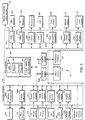
- Personal computer 12 includes a host processor 30 and a series of subsystems or adapters 34a-34p (hereinafter generally referred to as 34) each of which is connected to host processor by a bus 36. (If the configuration of personal computer 12 so dictates, bus 36 is replaced by a backplane.) If needed, one or more subsystems 34 can also be connected to host processor or to each other via a local bus (not shown).
- Host processor 30 provides an industry standard platform which supplies a common power supply, a computing function (CPU 38), memory and storage devices 40, mechanical support and cooling functions 42. Subsystems 34 gain access to any or all of these services via bus 36 in a motherboard implementation (or the backplane in a backplane implementation). Other systems outside the physical housing of personal computer 12 can gain access via subsystems 34 that externalize these functions from personal computer 12.
- Host processor 30 is a 486-66 based machine; alternatively, host processor 30 may be implemented as a workstation. Standard ISA bus architecture is used, but EISA architecture or others can be selected instead.
- the memory nad CPU and expansion slots are on a single board.
- the backplane configuration power and communication occur via the backplane, and CPU 38 and memory 40 plug into the backplane like an adapter.
- Subsystems 34 and host processor 30 communicate in a bidirectional fashion over bus 36. Each issues and receives commands, status and other information.
- Host processor software control 14 integrates and regulates the flow of information, and hence the operation of subsystems 34 and the input/output devices. Communications that conform to platform standards can be handled by bus 36. Specialized or nonstandard communication can be handled by local buses, like a local video bus (not shown). A local bus provides specialized communication of limited scope. Overall function of the local bus can be governed by communication that occurs over bus 36.
- preference database 20 can contain information regarding video gain and offset, image format preferences, and text data required for display of images obtained during endoscopy. Multiple settings or preferences can be accommodated and tailored to the (typically different) specifications of each physician. System configuration and real time operation are monitored by software defined logic to allow for dynamic optimization of all controlled functions. Decisions can be made based on operator input, like specification of procedure or surgeon. Decisions can also be made based on system generated input, like video level, color composition, or most recent operator interactions. Preferences can be modified by the operator, or dynamically by the system.
- An infra-red, programmable handheld remote control 48 provides operator interaction from a sterile field. Hard wired switches connected by wires to the operative field can also be used.
- the system also provides for multiple inputs from touchscreens, mouse, light pens and other relative and absolute pointing devices 56.
- the system is structured to be platform independent.
- the software provided for the system is organized so that portions of the code that are hardware dependent can be easily replaced.
- CPU and adapter subsystems are improved or changed, a means is provided to allow simple integration of the new devices.
- Input and output devices and specifications are stored in preference database 20, and control device specific outputs. For example, 24 bit color images can be processed to display on a 64 color gray scale device based on the database preference.
- the software system include heuristic systems that allow multiple complex functions to be controlled automatically or with minimal and simple operator input.
- the host/subsystem architecture allows for both standardized communication therebetween and the sharing of resources (such as memory and processing functions).
- Subsystems 34 identify themselves to host processor 30, send queries to and respond to queries from host processor 30, and provide signal and control outputs to host processor 30.
- Communication occurs over bus 36 between host processor 30 and subsystems 34 and between the subsystems 34 themselves.
- inputs can be applied to personal computer 12 either through the subsystems (e.g., subsystems 34a-34g) or directly to host processor 30.
- output signals and data are produced by both host processor 30 and the subsystems (e.g., subsystems 34j-34p).
- Fig. 2 illustrates several different types of subsystems 34.
- Camera subsystems 34a, 34b provide host interfaces for a camera 44 and a video endoscope 46.
- Remote control adapter 34c interfaces a remote control unit 48 (infrared or otherwise) to host processor 30.
- the physician can control system 10 using voice commands that are relayed from voice pickup 50 to host processor 30 by voice control adapter 34d.
- a fluid/gas monitor 34e relays signals from a fluid gas sensor 52 in the sterile field to host 30.
- Laptop, palmtop, and other computing devices 54, and pointing devices 56 communicate with host processor 30 via suitable adapters 34f.
- PCMCIA devices are interfaced with host processor by PCMCIA adapters 34g.
- Other input devices 58 (such as a keyboard and pointing devices such as a mouse) are connected directly to bus 36.
- Video subsystems 34j, 34k provide interfaces with a CRT display 60 and a television monitor 62.
- the level of light provided in the surgical field by an illuminator 64 is controlled by light source subsystem 341.
- a VCR subsystem 34m supplies image signals to a VCR 66.
- the operation of devices used in the surgical field, such as fluid supply 68 and one or more medical devices 70 are controlled via fluid management subsystem 34n and medical device subsystem 34o, respectively.
- Other output devices, such as printers and film recorders 72 are driven by host processor 30 via one or more PCMCIA adapters 34p, while some output devices 74 can be connected directly to bus 36.
- Preference database 20 can also be connected to host processor 30 via a PCMCIA adapter 34i.
- a PCMCIA adapter 34h is used to connect host processor 30 to units 76 that provide other services. Examples of other units 76 include storage devices, e.g., disk drives, memories (such as so-called “flash memories”), disk drives, and network adapters (for wire, wireless, RF, or optical networks). But any device that conforms to the PCMCIA connectivity standard (or any other suitable standard, such as JEIDA) can be connected to personal computer 12 in this fashion.
- any suitable port of host processor 30 e.g., serial, parallel, SCSI, etc.
- I/O capability e.g., serial, parallel, SCSI, etc.
- Video subsystem 34j resides on full length PC card, and contains the necessary processors and memory to allow real time gain and offset control, and matching of multiple inputs to multiple output timing specifications for display, pan, zoom, video overlay and digital signal processing.
- the multiple functions of video subsystem 34j include:
- video subsystem 34j receives an image 80 (to be displayed, e.g., on CRT display 60) in any suitable format (such as RGB, NTSC, Y-C, PAL, or PAL Y-C).
- the image is applied through an analog signal conditioner 82 and a range and offset controller 84 to an analog to digital converter 86.
- the digitized image is applied to a synchronization module 88, which also receives as inputs a camera synch signal 90 (and possibly other external triggers 92).
- Synchronization module 88 can also generate synch signals for one or more input devices (such as cameras).
- the synchronized image signal 94 produced by module 88 is passed to graphics processor 96.
- Graphics processor 96 performs the graphical functions described above (several of which are listed in box 98) on image signal 94.
- the image produced by graphics processor 96 is sent to frame buffer memory 100 for subsequent display.
- Graphics processor 96 also returns information about the live, processed image to host CPU 38 via bus 36 (or via a local bus within personal computer 12).
- CPU 38 responds to this information, and to the display preferences (from preference database 20) of the particular physician who is using system 10, by dynamically adjusting one or more display parameters of the live image.
- CPU 38 Examples of the processing performed by CPU 38 on the image include masking 102, keying 104, VGA-, video source-, or CPU generated-overlaying 106, and output leveling 108.
- CPU 38 adjusts 110 (where required by the preferences from database 20) such display parameters as display synch, pixel rate, and frame control.
- the resulting image information (consisting, e.g., of BLUE LUT, GREEN LUT, RED LUT, and SYNCH) provides the output 112 of video subsystem 34j.
- the zooming function performed by graphics processor 96 allows real time images or still images to be magnified by a user specified value.
- the zoom occurs concentrically about a point specified by the user or preference database 20, and is usually the central point of the image.
- Image processing is done to allow highest quality view of the magnified image. This is either a specific hardware routine or can be performed in software in a virtual frame buffer.
- execution of the zoom function adjusts an electrical potential output (not separately shown) that allows any external device to interpret the potential and adjust light intensity so that the light level is appropriate to the field of view.
- the electrical potential is related to the luminance or brightness of the reduced field of view caused by the zoom, as opposed to the entire incoming video signal. This allows appropriate light level for the area being visualized.
- a tag is placed in the image file.
- the tag alerts an output device that uses the image file to display or print the image as zoomed, i.e., in the same manner in which the image was displayed to the user at the time of capture.
- area of interest processing can be used to generate a light source control potential that is weighted for a defined area which is a subset of the entire viewing area.
- This area of interest can be dynamically changed by an algorithm in the software.
- System 10 also provides for manual, user prompted control of gain and offset, multiple values for gain and offset specified in preference database 20, and a real time process for automatic context and value sensitive means for control of gain and offset. Automatic adjustment is accomplished by mathematic processing of signal in areas of interest on the live or incoming video.
- video subsystem 34j allows images to be displayed in a variety of formats according to the preferences of the physicians that use system 10. For example, referring also to Fig. 5, a pair of video subsystems 34j, 34k are wire-ored together to produce a "picture-in-picture" output for display. Both images are applied to each video subsystem 34j, 34k. Each subsystem 34j, 34k processes one image and simply monitors the other image for synchronization purposes. For example, video subsystem 34j processes input 1 and monitors input 2, leaving it to video subsystem 34k to process input 2 (and monitor input 1). More than two inputs can be used, if desired.
- the image inputs may be either synchronous or asynchronous. That is, video signal synchronization can occur at the inputs to subsystems 34j, 34k via a system generated synch signal, or at the level of subsystems 34j , 34k in display management by CPU 38.
- Host CPU 38 and program 14 control the output video, the asynchronous video signals to a single output display.
- the wired-or connection provides a current drive that adds the two image signals together.
- the sizing, location, and priorities of the two images are selected, switched, and defined based on the preferences set forth in database 20 and the sterile field controls (e.g., remote control 48, Fig. 2) operated by the physician or other user.
- Each signal input can be processed controlled with the multiple functions discussed above.
- the CPU commands for handling the multiple images are in addition to the commands listed above, and are relayed to the subsystems 34j, 34k via bus 36.
- FIG. 6 another function performed by video subsystem 34j is capturing images from frame buffer 100 (Fig. 4) and storing the images in memory. Capture can occur by direct operator interactions (via, e.g., remote control 48 or a pointing device). A single button press can take a snapshot of the current information on the screen and transfer it to a memory media as a digital file. This system provides additional logic to allow toggle between "freeze” and “live,” until the desired image is frozen. The image can then be saved to memory (by executing save command 120, so the surgeon can elect to save or discard any image.
- the freeze and capture functions can be controlled by any data input device 22.
- the current implementation allows control by hardwired buttons on the camera or infra red handheld remote control.
- the review function 122 displays all images captured, either as a composite of many postage stamp size images, or as a sequence of full size images. This allows the operator to be sure adequate images have been captured.
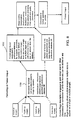
- Fig. 7 illustrates a "tour" function performed by system 10.
- Preference database 20 contains, for each physician who uses system 10, one or more "scripts" 130 for designated captures of images.
- system 10 prompts the physician 134 to capture images by anatomic site, pathology or other designation. Prompting is performed via a graphical object or a text clue imposed on the displayed image that guides the operator to the proper position for capture. The physician has the opportunity to skip an image or acquire additional images 136 during the tour.
- system 10 Upon the completion 138 of the script, system 10 has captured and identified a series of images 140 specified in the script.
- pre-op and post-op tours can be designated 142.
- Pre-op and post-op tours advantageously show pathology and post endoscopic procedure results or status. If multiple tours are specified, system 10 selects 144 the scripts for the tours from preference database 20 in a logical sequence that corresponds to the natural flow of the surgical procedure.
- the format of the printed output may identify the sites as pre- and post-intervention.
- the tour function also includes automatic annotation of images obtained in each tour with predefined text or graphical information 150.
- the tour can also specify composition of printed or other output, combining acquired images and/or stock images or diagrams that lend clarity and context to the images acquired (step 152). Page formatting allows multiple images in multiple sizes to appear on a single page or on multiple pages.
- Page layouts can be defined and modified based on a taxonomy defined when the user defines the functions of tour. Currently, the page description language is postscript level 2, but other interpreters for conversion to other file formats can bee added. Images captured in the tour mode will define how they will be displayed, arranged and labelled. Additional drawings, diagrams or stock images can be pulled into the page layout defined. Once defined, the layout can be stored, or printed to hard copy or slides.
- Images captured randomly (outside of a defined tour) in an unstructured capture 146 are formatted by a user defined algorithm, or a default format is used in the absence of user instructions to the contrary.
- This layout formats pages to conform to a predetermined optimum number of images and spatial arrangement based on the target printing or display device specified in the user preference (as set forth in preference database 20).
- a page layout for the prints will be generated consisting of a tour format plus a random format based on desired output device.
- the user can configure and modify the layout at any time. If no user selection is made, a default layout is used.
- system 10 also provides a simple technique for overlaying text or graphics on the acquired images (the technique can also be performed via a laptop or palmtop computer or other suitable computing device that is externally connected to personal computer 12).
- the resultant image is a composite of the annotation and overlay, so that the acquired image remains unchanged.
- the overlay text is anti-aliased for improved appearance. Anti-aliased text is used extensively throughout the interactions with the system.
- the starting point for the annotation procedure is the image file 160.
- the operator e.g., the physician selects the text or graphical objects with which to annotate the image using one or more suitable data input devices 22 (Figs. 1 and 2) (step 162).
- the input device is also used to locate the text or graphical object on the image (step 164.
- Object attributes such as font, color, and size, can be selected manually or may be supplied by preference database 20 (step 166).
- the information that specifies the size, location, and other attributes of the graphical object are stored as relative coordinates in an overlay (step 168), and thus do not affect the source image.
- the objects and text are resized as the image is scaled for display (step 169). Printed output of the image/overlay composite will appear as if the overlay were part of the image itself.
- Annotation can be performed in a similar manner at both the image and page layout levels.
- a single image or page layout can possess multiple annotation overlays.
- Single or multiple overlays may be composited with the image.
- the overlay may also possess the attribute of translucency, ranging from obliteration of the underlying image to transparency in areas in which the overlay is not visible.
- Single or multiple overlays may be attached to an image at any time.
- System 10 also displays system status and functions to the user in a format and style specified by the user.
- a CPU-directed video keyer (Fig. 4) adds the status overlay to the video signal displayed by the system, in much the same manner as discussed above.
- the overlay includes text information, graphics, or other images.
- Fig. 10 illustrates several different options available to the operator for entering the annotation information.
- An important functionality is "pen based” computing using a commercially available pen-based hardware 54 (Fig. 1) as the input device, but similar functionality may be obtained with other input devices.
- the endoscopic image is displayed, and the input device (e.g., the pen-based system) is used to annotate, manipulate, or process the image as discussed above.
- the input device e.g., the pen-based system
- the operator actually prints or writes on the screen, and system 10 translates the pen strokes into machine-readable characters.
- System 10 includes a search/shorthand capability to expand characters to an expected or defined word or most common "near hit.”
- the pen-based system also provides an extremely straightforward device for allowing the user to draw lines, squares, and circles, and for controlling area of interest processing and color.
- annotations are stored as text and location so that when video formats are changed, or images are scaled to larger or smaller sizes, that aspect ratio, location and contrast are maintained.
- system software 14 includes an image processing module or engine for enhancing the visual quality of images.
- Techniques implemented by software 14 include multiple methods for video noise reduction, masking, smoothing, sharpening, contrast and histogram adjustment, contrast stretch and contraction.
- Software 14 also analyzes the image and adjusts the algorithms to optimize the image based on predictable procedure, specialty, surgeon, or other predictive factors.
- Software 14 also uses multiple analyses of the source image to dynamically adjust the image processing parameters.
- Files created by system 10 are stamped with an internal "authentication" code not accessible to the user to designate the file as uncorrupted or structurally changed for legal purposes. Any image process that would substantially alter the information contained in the file causes this stamp to be modified, thereby indicating that the file is no longer primary source documentation.
- the utilities provided to cause image modification provide an opportunity to copy the image prior to modification so that alterations can be performed without compromising the evidentiary quality of the documentation.
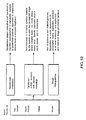
- video subsystem 34j processes images obtained during endoscopy for display on virtually any type of display device and in any suitable format.
- Preference database 20 supplies the conversion information that specifies the file type of the output image and the process to be performed (step 170).
- Video subsystem 34j uses this information to process the raw image data 172 (step 174). It is at this point that the authentication code is applied to the image file (step 176). If desired, external conversion utilities are applied to the image file (step 177).
- the image output file 178 is then processed for display (step 179) in any of the formats listed in Fig. 11.
- Processing occurs via a process of color reduction, whereby in the transition from a high (e.g., 24) bit depth to a lower bit depth (e.g., 16, 8, or gray scale), the process is one of calculated selection of specific color representations to be retained (as opposed to arbitrary file truncation).
- a high bit depth e.g., 24
- a lower bit depth e.g., 16, 8, or gray scale
- controls of a VCR 66 are programmable using one or more data input devices 22 (e.g., remote control 48). Signals from remote control 48 are interpreted by a command interpreter in remote control adapter 34c according to preferences stored in databases 20 which associate actions taken by remote control 48, such as the actuation of one or more buttons on the device, with a command).
- the command interpreter relays the appropriate command (e.g., for record, stop, pause and play) to VCR subsystem 34m, which in turn transmits the commands to VCR 66, either via a hardwired connection or via interpreted and generated infra red signals.
- Frame addresses are stored in the imaging system database, and can be used to index, record and playback videotape on a frame accurate basis.
- System 10 is also capable of interactive recording or playback of audio signals.
- the audio material is written to and played back from digital files by an audio adapter subsystem 34 (not separately shown in Fig. 2).
- the remote control devices include infrared remote control 48 and voice pickup 50; other remote control techniques, such as detection of pupilary eye movement or the closure of contacts on, e.g., a footswitch, may also be used.
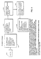
- the subsystem 34 associated with the device In response to an action taken by the operator, such as the depression of a button on IR remote control 48 (step 180), the subsystem 34 associated with the device (in this example, remote control adapter 34c) detects the signal (step 182) and interprets the signal (step 184) using information stored in an internal memory (not shown). Subsystem 34c then accesses preference database 20 (step 186) to determine the action to take in response to the operator's command. The action is communicated to the device driver for the device that is impacted by the command (step 188), and the action is performed. Thus, a generic action taken by the operator is translated to a device-specific instruction according to the preferences of the particular operator stored in preference database 20.
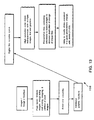
- Slide function 190 allows:
- Image information may be used by many presentations, and stored only once.
- the system database (discussed below) allows for this by supporting "one-to-many” and “many-to- many” data relationships. Slides, images on slides, or any other element comprising a slide may be shared by greater than one presentation. An object will continue to exist until all presentations that call it are modified or deleted.
- Slide function 190 performs the following operations:
- Multiple images may be scaled and positioned on a single slide.
- the appropriate scaling and positioning will be done on the fly from the appropriate source image, leaving the source image unchanged.
- High quality antialiased text will be available in multiple fonts and point sized for overlay and text functions.
- Image information will be displayed in a "rough cut” version for processing speed.
- a presentation may be viewed as multiple miniature representations of the component slides on a single screen.
- the slides can be moved or modified using any pointing device to restructure the presentation. This can be done on a laptop, personal computer, pen based system, or workstation.
- a presentation may be queued for printing.
- the system will automatically control a digital film recording device, transferring the digital files to film. Automatic recording of number of available frame and errors will be incorporated. This should allow for most slides to be printed and discarded, allowing all filing to be conveniently located on the machine.
- a simple interface allows the operator to view and edit slides in a so-called "what you see is what you get” presentation.
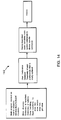
- the device handling architecture 192 implemented by system 10 is illustrated.
- This architecture allows many devices 16, 18, 22, 26 (Fig. 1) to be supported by a single operating program 14.
- Custom configurations are stored in a taxonomy in preference database 20, which is referenced during the configuration and operation of system 10.
- This architecture, and the structure and organization of the database allows system 10 to be platform and device independent -- that is, when a device is added to or removed from the system, only the software driver that controls that device need be changed. Portions of the programs or device drivers may reside in host processor 30, the device itself, or on other media or memory accessible to host processor 30 and the device.
- Fig. 15 illustrates the connectivity and operation of a PCMCIA adapter 196 (e.g., adapters 34f-34i and 34p of Fig. 2).
- PCMCIA is an evolving standard for an array of devices that include storage, communicating and other external functions.
- the PCMCIA (or any other suitable standard, such as JEIDA) is used to interface to multiple input and output devices in a standard manner.
- PCMCIA adapter 196 is self-contained and durable, and is equipped with a standard edge connecter for ease of use. No additional wiring is required; the adapter slot provides operating power.
- the action of inserting adapter card 196 into the slot in host processor 30 is all that is required to initiate appropriate identification and management of the device that is inserted.
- a PCMCIA adapter 196 may alternatively be located externally to host processor 30.
- a PCMCIA adapter 196 may be disposed in another device (such as a laptop or palmtop computer 54, Fig. 2, that communicates with host processor 30.
- Fig. 16 illustrates options 200 provided to the user by preference database 20 and shows how the user and CPU 38 interact with preference database 20.
- Options 200 include specifications as to video format 202, processing 204, the video sources to be used 206, and the configuration of the hardware 208.
- information concerning the users 210 and the hospital (or other facility in which system 10 resides) 212 is also provided.
- the attributes of the stored data 214, relationships between the data 216 are also provided, as are calculated data field attributes 218 (such as required entry, text, date, numeric, or decimal; other types of data fields are date and time).
- Preference database 20 classifies the preference information according to the individual physician, specialty, procedure, and stage of procedure to give the physician the capability of configuring and operating the devices in system 10 rapidly, according to his or her pre-stored preferences.
- CPU 38 retrieves the preference information for this physician and procedure and uses it to configure the devices (e.g., cameras, CRT displays) preferentially used by the physician during the procedure (step 222).
- CPU 38 also maintains and updates the preference information in response to changes ordered by the physicians.
- Figs. 17 and 18 illustrate procedures for storing images in and retrieving images from an image database.
- the image database can reside in any suitable memory device in system 10 (e.g., disk storage).
- the external view of system 10, to the end user, is that of a medical specific application, designed to handle both the capture and storage of real-time data, as well as the maintenance and manipulation of the data and relationships of the data to other associated information.
- This external view can be represented by Fig. 19.
- the end user first encounters a login procedure 240, which admits him or her to system 10. The user may then go to either Data Acquisition (Procedure) 250 or Information Processing (Query) 260. Both of these two sub-systems can invoke a signal processing subsystem 270 and an output subsystem 280.
- Data Acquisition Procedure
- Query Information Processing
- the primary non-medical features of program 14 (Fig. 1), from the end users view, include:
- Program 14 has been designed to be as simple as possible to the end user. This means that program 14 uses heuristic approaches, in many cases, to avoid having to ask complex questions to the user.
- Program 14 is designed to run on a multitude of platforms, and to allow many forms of input and output. This allows program 14 to be easily maintained, upgraded and expanded, and is not limited to availability of specialized equipment.
- Program 14 as illustrated in Fig. 19, embodies a much larger set of engines (i.e., software modules) running under the surface.
- Each engine is designed to provide a fairly easy mechanism for maintaining a flexible environment. Flexibility includes the ability to make major changes in both the functionality and presentation of the software, as well as to provide platform independence for easy integration of new software and hardware.
- program 14 is divided into several engines each of which is devoted to a particular portion of the application, and is designed to integrate well with the other engines in the application.
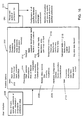
- the engines included in this application are described below: MOM 300 Menu management engine EMM 310 Memory management engine RA 320 Raster engine DAD 330 Platform independent display engine THE 340 Input device engine GENERAL 350 general handlers for system independence IGGY 360 Signal processing engine POP 370 Output device engine SIS 380 Database engine
- Fig. 20 shows the interconnectivity of the engines, and their overall location within the application.
- Menu management engine 300 handles the creation and maintenance of the entire software application that executes in system 10. To control MOM 300, the application describes menus as a series of encapsulated data arrays.
- the data arrays embody the following information:
- MOM 300 is designed to handle any number of "windows" on a display screen.
- the above data arrays describe both the look and feel, as well as the functionality of each window.
- a “window” may consist of a background and one or more buttons.
- a background describes how the window appears, and is not limited to any particular look.
- a button is an entity which exists on top of the background, and provides either information or functionality. When providing information, the button retrieves some data and displays it to the user in an understandable manner. When providing functionality, the button causes some action or actions to occur when the user "pushes" the button (e.g., by touching the button on a touchscreen or activating it with a mouse).
- MOM 300 uses an integrated help system to allow the user to query both windows as well as buttons to see thier functionality or use before being required to actually use the system.
- the help system is embodied in the menu and button descriptions themselves, and thus afford easy change and upgrade with the software.
- MOM 300 allows the display of windows to overlap, and handles complete maintenance as to the order and depth of windows, as well as the displaying of the windows which become revealed through use.
- MOM 300 In addition to the multi-window approach used by the menu manager, MOM 300 also provides multi-processing on the window level, as the user is never restricted to working only on the "top" window. Through dynamic array switching, MOM 300 allows the user to select any visible button, regardless of the associated window or its depth in the screen. Because of this, MOM 300 implements a flat window scheme where no window has precedence over any other window.
- MOM 300 does include an ability to simulate the more traditional hierarchical menu structures, if the need arises.
- MOM 300 performs its work in a fairly straightforward manner. When an application beings to run the first thing done by the program is to invoke MOM 300 routines to open one or more windows. Once this is accomplished, the program then invokes MOM 300, which takes complete control of the program from that point on.
- MOM 300 analyzes the existing menu structures and begins to query the users requests via THE engine 340. Display of the menus, as well as display of the users input device and selection of choices, is handled within MOM 300 by calling RA engine 320 to draw the desired information, and DAD engine 330 to display it to the current output device.
- MOM 300 is also responsible for all event handling at the menu level. MOM 300 can be made to poll events at every input device cycle, and maintains, among other things, a real time clock for timing of events and maintenance of a time-of-day clock. MOM 300 uses THE engine 340 for event polling, but allows button functionality to uncouple event polling for specialized event handling within a buttons action.
- MOM 300 never terminates, unless all windows are closed without a new window being opened prior to functionality return. Besides this method, the only other method of termination is direct exit within a function.
- ECM Memory Management Engine
- EMM engine 310 is responsible for the allocation, maintenance and freeing of the data arrays used by RA engine 320 and the other functionality portions of the program. Despite the fact that modern programming software provides memory allocation, the use of EMM engine 310 assures platform independence when moving between software platforms as well as hardware memory platforms.
- EMM engine 310 is a fairly simple code system which allocates memory in "pages" or “blocks” when requested by the rest of the software. EMM 310 maintains data lists to track the memory, and provides boundary checking as well as freeing of the data when its use is complete.
- EMM 310 also provides the ability to query the memory system for remaining quantity and availability, allow the software to provide status, as well as predict remaining capability.
- EMM 310 is used by MOM engine 300 to allocate the memory used for the windows (see the section below on RA engine 320 for a more detailed description) as well as being available to all the other engines as needed.
- RA engine 320 is the main drawing engine responsible for drawing the menus and their associated buttons and backgrounds. Because this software system is designed to be platform independent, RA 320 does not draw to any output device. Instead, RA 320 interfaces with EMM engine 310 and draws to EMM allocated memory. Actual display of the windows on the users display device is handled by DAD engine 330. This type of architecture is termed a virtual frame buffer.
- RA 320 is driven directly by MOM 300, and in some cases by the application functionality itself.
- RA 320 is a table dispatched service and takes as input a pointer to a heterogeneous data array. This data array consists of pointers and data, where the pointers correspond to a token list which embody a primitive graphics language.
- RA 320 contains the minimum needed set of drawing devices to render all menu drawing. This includes gradient rectangles, antialiased and non-antialiased text, circles and lines, as well as more complex concepts such as buttons, sliders, controls, LED's, and textured backgrounds.
- RA 320 also provides programmer definable tokens, via a functional token, with which the programmer can vector to thier own code during a RA token execution. This enables the program to draw any type of object, even objects never conceived before in the software.
- RA 320 is limited to drawing to a single window at a time, and many not mix drawing to different windows within a single token download. Therefore it is up to MOM 300 to direct RA 320 as to the appropriate window for drawing, as well as providing RA 320 with the correct token list, as extracted from the menu arrays.
- RA 320 is designed to allow self-modification during the execution of a RA token list.
- a token list can self-modify while executing, allowing decisions to be made on the fly, as to future drawing which is still down-stream from the current point of token execution.
- RA 320 always draws via EMM engine 310, in a standard method. While the method is modifiable, it is a fixed preapplication, as per the programmer's judgment. For example, within this application, RA 320 is defined to be 24 bit (8 bit per pixel) in a Packed architecture (RGBRGBRGB ). By splitting RA 320 and DAD 330 apart, and allowing DAD 330 to handle device particulars, DAD 330 can color reduce/expand, as well as resolution reduce/expand the RA maintained EMM memory buffers when displaying to any device.
- Font drawing is handled in RA 320 by use of precomputed raster font tables.
- the font tables contain a byte per pixel, which indicates the natural antialiasing of the font at that pixel. Fonts are encoded such as to be both proportional as well as non-proportional, and any font may be displayed in any combination of antialiasing and proportionality. When fonts are displayed, an additional font transparency sets the level of opacity, allowing for drop shadows and other effects. Font color is specified as a 24 bit (RGB) value, which is used with the transparency and antialiasing information to calculate the appropriate color for each pixel.
- RGB 24 bit
- DAD Platform Independent Display Engine
- DAD engine 330 handles actual updates of information to the user's end display device. Since the software system is device independent, DAD 330 coordinates requests from MOM 300 and the user's functionality, and reads EMM memory and displays the memory to the current device.
- MOM 300 following advice from the menu structures, instructs RA 320 to draw the various windows to EMM memory. After RA 320 completes the drawing, MOM 300 then instructs DAD 330 to take the completed memory and display it on the current display device.
- DAD 330 When DAD 330 receives an instruction to display a piece of EMM memory, it consults the MOM structures to determine the location of the memory, and the desired location of its display. Because DAD 330 is purely BLIT oriented (e.g., high speed rectangles), the drawing is both efficient and space saving. Since all display devices have inherent differences, it is DAD's responsibility to call the appropriate routines at the proper time, for each display device.
- routines which the display device is capable if need be supported. Routines which are not possible for that display device need not be stubbed, and DAD 330 is simply informed of thier absence and handles it gracefully.
- the routines required embody a small set of primitives, which include area blitzing, line blitzing, high speed rectangle drawing, high speed or outlined rectangle drawing and cursor support.
- Other routines, not necessarily supported by all devices include, acquisition, high-speed unpacked blitzing and automatic packing and unpacking routines.
- DAD 330 In order to make DAD 330 handle the platform independent drivers, the software calls a standardized set of routines, which are table dispatched at runtime. Because of the table dispatch method, no comparisons are required to locate a routine within a driver. Instead, all execution is handled by hashed indexing which provides near-instantaneous access to all drivers an all functions. Note that because DAD is responsible for both input and output display devices, it handles any video acquisition required by video data software within the user's procedure program. This requires that DAD 330 coordinate with SIS 380 and MOM 300 at the proper time, for control and decoding of incoming video.
- TCE Input Device Engine
- THE engine 340 is designed to be a device independent input event handler. THE 340 is invoked by both MOM 300 and the users functionality, to retrieve spatial and textual information from the user. Because the software is input device independent, THE 340 is responsible for the combination of multiple pointing devices, and can handle more than one input device simultaneously, as well as being able to switch input device context on the fly.
- THE engine 340 is basically divided into two sections: textual and spatial.
- the textual handler involves reading textual data from keyboard devices and transmitting them, when requested, to MOM 300 and functional software. Textual handling includes not only input and maintenance of text buffers, but also flushing of all textual queues.
- Spatial handling is performed by determining the location and types of input devices. Because input devices fall into two categories, absolute and relative, THE engine 340 automatically converts all coordinate, regardless of their type, into absolute coordinates. These coordinates are automatically clipped, by THE engine 340, against the current screen resolution as defined by DAD engine 330.
- THE engine 340 is its coupling with MOM 300 for mouseless handling of menu structures. Because MOM 300 allows menus and buttons to exist anywhere on the screen, even layered, the software which allows the user to move from "field” to "field” (including buttons) must be able to dynamically analyze the "best next" button to go to, from the current button. This is especially important when considering the fact that the user may modify the look for the o menus, on the fly. Therefore, a fixed rule for moving fro button to button via cursor keys is out of the question. THE engine 340 handles this, with help from MOM 300, by keeping track to two cursor locations. The current absolute cursor, and the current field cursor.
- the field cursor marks the current (or most recent) choice executed by the user (e.g., the last button picked).
- a cursor movement command is detected by THE 340, it uses MOM engine 300 to retrieve the menu descriptions, and analyzes these descriptions in an attempt to determine the best location to move to, and then performs the move to that location. This form of dynamic sensing affords the most flexibility to the entire application.
- GENERAL engine 350 handles all routines which are fairly standard, but which for one reason or another are desirable to have under platform independent control of the application. This includes items such as non-EMM engine memory acquisition and freeing, as well as file I/O. GENERAL 350 is engine present to give a simple and global mechanism for error control and handling. This provides the software package with a uniform mechanism for error recovery, which otherwise may be handled in a less than elegant way by the operating system of run-time program.
- IGGY engine 360 is responsible for all digital signal processing of acquired wave form (i.e., image) data. IGGY 360 is commanded primarily by MOM 300 and the functionality used to perform some form of wave form processing (usually image processing). Instead of being an integrated engine (as are MOM 300, RA 320, DAD 330, and the other engines), IGGY 360 is a set of separate routines, which may be used and combined to perform high level processing of acquired data.
- IGGY 360 Due to the nature of the application, in that the end user does not possess the education necessary to perform high-end signal processing, IGGY 360 is designed to have heuristic processes which allow it to analyze wave from data and determine the best enhancements necessary. IGGY 360 can use MOM 300 to request minimal information from the user, but in general does not do so except in the simplest of cases.
- IGGY 360 embodies at least the following basic signal processing techniques:
- IGGY 360 provides these services in an on-call manner, the analysis services utilize heuristic techniques to determine if the other services are required to provide the best output data possible.
- POP engine 370 is to the output devices as DAD 330 is to the input devices. For each output device supported, POP 370 provides interface mechanism for that device. POP 370 also provides limited input from some of these devices, as the device requires. POP 370 is responsible for maintaining output (and sometimes input) to the following devices:
- POP 370 is responsible for some diverse device handling. POP 370 places the devices into “like” categories, and provides a uniform mechanism for calling "like” devices. For example, all drives, flash cards and networks are driven in a like manner, while modems have their own mechanism, just as printers and film recorders. Since MOM 300 directs the output activities, POP 370 is never confused as to how the service is intended (e.g., each service is specialized, and thus POP knows the appropriate need and duty).
- POP 370 While most of handling provided by POP 370 requires simple interfacing to outside drivers, or the operating system, the printer and film recorder interfaces of POP 370 are highly particular to the device being addressed. Furthermore, because of all the possible formats for output devices, POP 370 interfaces with MOM 300 to provide the user with a visual mechanism for the specification of output format. For example, under printer interface, POP 370 can direct MOM 300 to display a grid of images, and have the user select the appropriate image and its location. Furthermore, POP 370 interfaces with RA 320 to allow the user to annotate the images prior to output. POP 370 handles interpolation of incorrectly sized data, and can utilize in-memory fonts as well as printer provided fonts, depending on the hardware capabilities.
- SIS engine 380 is the database handler. It is responsible for handling all database activities which include user management, forms management, data management and signal processing management.
- MOM 300 User management is invoked by MOM 300 to confirm a user and to set a users profile for the display of MOM menus.
- Forms management handles the design, storage and retrieval of forms.
- Data management handles the storage and query of data from within forms.
- Signal processing management is a subset of data management, and is responsible for the handling of signal data within a form.
- program 14 is designed to be a specific medical application, even though the engines provide a much greater, and universal capability.
- the overriding flow control is a section of the software which dictates to MOM 300, POP 370, SIS 380, and IGGY 360 a particular method to follow for user flow control. It is this overriding flow control which provides much of the automatic handling which is required by the naive user.
- Fig. 19 when the user invokes the program 14 at login time, the user is greeted by an opening screen and requested to enter a user name and password. Once entered, these elements are cross compared, via SIS 380, against the valid users in the database. When a valid user is identified, his user profile is loaded, and MOM 300 is informed of any changes to the environment.
- procedure flow control 260 is followed; otherwise, information flow control 250 is followed.
- procedure handler accesses the user's procedure form and displays it to the user. This is some form, entered for or by the user, when the user is given original access to the software.
- the form which is assigned to the user may be modified at any time via the information processor.
- the procedure flow control 260 is launched. This causes DAD 330 to invoke acquisition and control is switched to the user.
- THE engine 340 monitors a special remote control, used during procedures (or, optionally, the keyboard), and causes various video functions to be executed. These include, but are not limited to:
- Captured images are sequentially numbered and named, and are stored on the current mass storage device via POP 370.
- SIS 380 is automatically called to store all, or only approved images into the database, associated with the current form.
- the user may review all captured images, and optionally delete unwanted images or invoke special image processing on selected images. Images selected for special image processing are processed automatically and overwritten with the new results.
- a removable media device e.g., FLASH memory, etc.
- the information handler is invoked upon successful login, when the user either does not have an associated procedure, or does not wish to access procedure.
- the user is first greeted with a list of available forms (via SIS 380). The user may select an existing form, or select a "new form" option to create a new form. If the user opts to create a new form, the various form elements which are available are shown to the user, plus the ability to create new form elements.
- a form element is any item when exists on any other form.
- the form When the user picks an existing form, the form is loaded with blank data. The user may fill out one or more of the fields in the form, and either enter the form into the database (e.g., enter the instance of the new data) or else request a query.
- SIS 380 When a query is requested, SIS 380 will attempt to fulfill the missing elements of the form, based on the fields which have been filled in. Upon retrieving the list of available responses, the user is shown the list and allowed to pick an item from the list. Once picked, SIS 380 will load the form with the appropriate data, and will display it to the user. Images, or other signal processing data within the form, when selected, will invoke a image browsing menu which displays all associated images with the form. Further selection of an image will cause IGGY engine 360 to be accessed for full signal processing by the user.
- Information processing procedure 250 also allows the user to format and output query responses to the printer, in a variety of looks, all handled by POP 370.
- information processing procedure 250 allows new users to be added to the system, and existing users to be removed from the system.
- preference database 20 and all image databases are organized in a manner that maximizes the flexibility of adding, modifying, or deleting information from the databases at will, without rebuilding or restricting availability of data.
- the structure of the databases is relatively simple, which keeps the data model independent of features of host data storage.
- database subsets (datasets) can be derived, extracted and manipulated remotely and then merged back.
- Each data element is stored independently in database storage. That is, there is no record relative pointer structure in the dataset. All "pointers" are data relative.
- One advantage of this arrangement is that if a database file is damaged, pointer chain corruption (which could damage other stored data) is avoided.
- a dataset may be transformed into plain text to allow for portability.
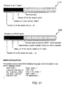
- Dataset storage is implemented using two record types, the "what" record 400 and the “it” record 410.
- "What" records 400 describe the data dictionary, while “it” records 410 contain the actual data.
- Each "what" record 400 and "it” record 410 has a randomly generated numeric key that has no special significance other than that it is unique to that specific record in the database.
- the data dictionary (i.e., the mechanism that describes the types of data contained in the dataset) is held in "what" records 400.
- a simple address book data set could require just two "what" records 400 -- one for a name and one for an address.
- the actual address book data is held in "it” records 410.
- One "it” record 410 is used for each name, and one "it” record 410 stores each address.
- the address book entry "it" records 410 are: 1234:0:1024:John Doe 5748:1234:3046:911 Main St. 8674:1234:4096:(312) 555-1212
- That what/it method also lets us extract a subset of records by first obtaining all of the "what” records and then obtaining all of the desired "it” records by the "its_what” fields.
- system 10 has been described with reference to endoscopy, the system may also be used for other medical procedures, surgical or otherwise.
Abstract
Description
- This invention relates to managing information in an endoscopy system, and in particular to controlling the acquisition, processing, storage, and display of endoscopic images.
- During an endoscopic surgical procedure, the surgeon typically uses a video camera (or other suitable device, such as a video arthroscope) to capture images of the surgical site. The images are generally applied to a display device (such as a television monitor) for observation. In some cases, the images are stored on video tape (by, eg, a VCR) or are converted to digital files for storage in memory or on a disk drive. Different physicians often use the video equipment in different ways.
- Proceedings of the fifth Annual IEEE Symposium on Computer Based Medical Systems, Durham, NC, USA, June 14-17, 1992, pages 156-169; S. Franchi et al "Multimedia perspectives for next generation PAC systems" describes systems for acquiring images during a medical procedure which comprises a preference database and which uses preference information. The system includes means for receiving an indication of user identity and performs image processing operations setting out the configuration of input/output devices. However, the system is not described as using a prompting means.
- The invention relates to a system for acquiring medical images as set out in appended
claim 1. - Other features and advantages of the invention will become apparent from the following detailed description, and from the claims.
-
- Fig. 1 is a block diagram of a system for managing endoscopy information according to the present invention.
- Fig. 2 shows one possible configuration of the system of Fig. 1.
- Figs. 3 and 4 shows details of a subsystem used in Fig. 2.
- Fig. 5 shows two subsystems of Fig. 2 connected in parallel for so-called "picture-in-picture" display of images.
- Fig. 6 illustrates a procedure for capturing and storing images in the system of Fig. 1.
- Fig. 7 shows a "tour" procedure for capturing images in the system of Fig. 1 according to a predefined script.
- Fig. 8 is useful in understanding how the system of Fig. 1 formats printed outputs of images.
- Fig. 9 illustrates a procedure for annotating images obtained by the system of Fig. 1 with text and graphics.
- Fig. 10 is useful in understanding a character recognition feature of the system of Fig. 1.
- Fig. 11 shows a procedure implemented by the system of Fig. 1 to convert the video format of an input image to a different video format for use by an output device.
- Fig. 12 is useful in understanding the operation of a remote control feature of the system of Fig. 1.
- Fig. 13 shows a procedure performed by the system of Fig. 1 for producing slides from the acquired images.
- Fig. 14 shows the device handling architecture of the system of Fig. 1.
- Fig. 15 illustrates the use of universal connectivity devices (that use, e.g., the PCMCIA standard) in the system of Fig. 1.
- Fig. 16 is useful in understanding the operation of a preference database of the system of Fig. 1.
- Figs. 17 and 18 illustrate the storage of acquired images in an image database of the system of Fig. 1.
- Fig. 19 is a flow chart that shows the operation of the system of Fig. 1 from the standpoint of the user.
- Fig. 20 shows modules of a software program that controls the overall operation of the system of Fig. 1.
- Fig. 21 is useful in understanding the structure and organization of the databases used in the system of Fig. 1.
-
- Referring to Fig. 1, endoscopic
procedure management system 10 employs apersonal computer 12 which executes astored program 14 to configure and manage all devices used by a physician during endoscopy. In particular,personal computer 12 receives images generated by one or moreimage input devices 16, processes the images according to the preferences of the physician performing the endoscopic procedure, and transmits the processed images to one or moreimage output devices 18 for display or storage. -
Personal computer 12 obtains information concerning the physician's preferences about the processing, display, and storage of the images from apreference database 20. As described in more detail below,preference database 20 is organized by physician - - that is, the preferences of each physician recognized bysystem 10 as to the image processing and the configuration and operation ofimage input devices 16 andimage output devices 18 are stored inpreference database 20 according to the identity of the physician and according to the various procedures performed by the physician. As a result, when a physician logs onto system 10 (as described below) and identifies the endoscopic procedure that he or she is to perform, hostcomputer 12 configuresimage input devices 16 andimage output devices 18 and controls the processing of the obtained images according to the information stored inpreference database 14. - A wide variety of
image input devices 16 can be used with endoscopicprocedure management system 10. For example,image input devices 16 include video endoscopes, cameras, video cassette recorders (VCRs), X-ray scanners (which convert X-ray films to digital files), digital X-ray acquisition apparatus (which convert X-ray photons to a digital bitstream or file), fluoroscopes, CT scanners, MRI scanners, ultrasound scanners, and other types of scanners (handheld or otherwise). - Likewise, several different types of
image output devices 18 can be connected tosystem 10. Examples include cathode ray tube (CRT) displays, television monitors, LCD panels and screens, EMM memory, and disk memory. The displays may use the RS170 format (i.e., RGB, Y-C, NTSC, PAL, or the PAL equivalent of Y-C), or alternatively may be non-RS170 devices (interlaced and non-interlaced display devices). As described in detail below, video subsystems connected withinpersonal computer 12 define communication protocols (e.g., horizontal and vertical synch, interlaced vs. noninterlaced display, scan speed, and spatial and color resolution) to image input andoutput devices - In addition,
personal computer 12 also receives data and commands from one or moredata input devices 22.Data input devices 22 include computing devices such as laptop and palmtop computers, as well as pen-based command systems.Data input devices 22 also include programmable input devices (such as infrared remote control units), and pointing devices such as a keyboard, mouse, trackball, airmouse, light pen, touch screen, and tablet. All of these devices allow the physician (or another used located, e.g., in the sterile field) to manage the operation ofsystem 10, as described in detail below. -
Personal computer 12 can also be connected (either directly or via a network or modem) to one ormore databases 24 to receive patient and other information. Examples ofdatabases 24 include hospital information systems and local databases located in the physicians' offices. - Numerous
data output devices 26 are also connected topersonal computer 12 for receiving data concerning the operation of system 10 (e.g., reports).Personal computer 12 also sends data to one or more ofdatabases 24 for storage. Examples ofdata output devices 26 include laptop, palmtop, and pen-based computer systems. - Referring also to Fig. 2, one possible configuration of
system 10 is shown.Personal computer 12 includes ahost processor 30 and a series of subsystems oradapters 34a-34p (hereinafter generally referred to as 34) each of which is connected to host processor by abus 36. (If the configuration ofpersonal computer 12 so dictates,bus 36 is replaced by a backplane.) If needed, one ormore subsystems 34 can also be connected to host processor or to each other via a local bus (not shown). -
Host processor 30 provides an industry standard platform which supplies a common power supply, a computing function (CPU 38), memory andstorage devices 40, mechanical support andcooling functions 42.Subsystems 34 gain access to any or all of these services viabus 36 in a motherboard implementation (or the backplane in a backplane implementation). Other systems outside the physical housing ofpersonal computer 12 can gain access viasubsystems 34 that externalize these functions frompersonal computer 12.Host processor 30 is a 486-66 based machine; alternatively,host processor 30 may be implemented as a workstation. Standard ISA bus architecture is used, but EISA architecture or others can be selected instead. In the motherboard configuration, the memory nad CPU and expansion slots are on a single board. In the backplane configuration, power and communication occur via the backplane, andCPU 38 andmemory 40 plug into the backplane like an adapter. -
Subsystems 34 andhost processor 30 communicate in a bidirectional fashion overbus 36. Each issues and receives commands, status and other information. Hostprocessor software control 14 integrates and regulates the flow of information, and hence the operation ofsubsystems 34 and the input/output devices. Communications that conform to platform standards can be handled bybus 36. Specialized or nonstandard communication can be handled by local buses, like a local video bus (not shown). A local bus provides specialized communication of limited scope. Overall function of the local bus can be governed by communication that occurs overbus 36. - The communication afforded by
bus 36 allows for software control of the specific functions ofsystem 10. For example,preference database 20 can contain information regarding video gain and offset, image format preferences, and text data required for display of images obtained during endoscopy. Multiple settings or preferences can be accommodated and tailored to the (typically different) specifications of each physician. System configuration and real time operation are monitored by software defined logic to allow for dynamic optimization of all controlled functions. Decisions can be made based on operator input, like specification of procedure or surgeon. Decisions can also be made based on system generated input, like video level, color composition, or most recent operator interactions. Preferences can be modified by the operator, or dynamically by the system. - As discussed below, multiple control devices are supported. An infra-red, programmable handheld
remote control 48 provides operator interaction from a sterile field. Hard wired switches connected by wires to the operative field can also be used. The system also provides for multiple inputs from touchscreens, mouse, light pens and other relative andabsolute pointing devices 56. - The system is structured to be platform independent. The software provided for the system is organized so that portions of the code that are hardware dependent can be easily replaced. As CPU and adapter subsystems are improved or changed, a means is provided to allow simple integration of the new devices. Input and output devices and specifications are stored in
preference database 20, and control device specific outputs. For example, 24 bit color images can be processed to display on a 64 color gray scale device based on the database preference. - As also discussed below, the software system include heuristic systems that allow multiple complex functions to be controlled automatically or with minimal and simple operator input.
- The host/subsystem architecture allows for both standardized communication therebetween and the sharing of resources (such as memory and processing functions).
Subsystems 34 identify themselves to hostprocessor 30, send queries to and respond to queries fromhost processor 30, and provide signal and control outputs to hostprocessor 30. - Communication occurs over
bus 36 betweenhost processor 30 andsubsystems 34 and between thesubsystems 34 themselves. As can be appreciated from Fig. 2, inputs can be applied topersonal computer 12 either through the subsystems (e.g.,subsystems 34a-34g) or directly tohost processor 30. Likewise, output signals and data are produced by bothhost processor 30 and the subsystems (e.g., subsystems 34j-34p). - Fig. 2 illustrates several different types of
subsystems 34.Camera subsystems camera 44 and avideo endoscope 46.Remote control adapter 34c interfaces a remote control unit 48 (infrared or otherwise) tohost processor 30. The physician can controlsystem 10 using voice commands that are relayed from voice pickup 50 to hostprocessor 30 byvoice control adapter 34d. A fluid/gas monitor 34e relays signals from a fluid gas sensor 52 in the sterile field to host 30. Laptop, palmtop, andother computing devices 54, andpointing devices 56 communicate withhost processor 30 viasuitable adapters 34f. PCMCIA devices (discussed below) are interfaced with host processor byPCMCIA adapters 34g. Other input devices 58 (such as a keyboard and pointing devices such as a mouse) are connected directly tobus 36. -
Video subsystems CRT display 60 and atelevision monitor 62. The level of light provided in the surgical field by an illuminator 64 is controlled by light source subsystem 341. AVCR subsystem 34m supplies image signals to aVCR 66. The operation of devices used in the surgical field, such asfluid supply 68 and one or more medical devices 70 (e.g., surgical tools such as shavers, abraders, end cutters, etc.) are controlled viafluid management subsystem 34n and medical device subsystem 34o, respectively. Other output devices, such as printers andfilm recorders 72 are driven byhost processor 30 via one ormore PCMCIA adapters 34p, while someoutput devices 74 can be connected directly tobus 36. -
Preference database 20 can also be connected to hostprocessor 30 via a PCMCIA adapter 34i. APCMCIA adapter 34h is used to connecthost processor 30 tounits 76 that provide other services. Examples ofother units 76 include storage devices, e.g., disk drives, memories (such as so-called "flash memories"), disk drives, and network adapters (for wire, wireless, RF, or optical networks). But any device that conforms to the PCMCIA connectivity standard (or any other suitable standard, such as JEIDA) can be connected topersonal computer 12 in this fashion. In addition, any suitable port of host processor 30 (e.g., serial, parallel, SCSI, etc.) can be used to provide I/O capability. - Referring to Figs. 3 and 4, details of
video subsystem 34j are shown. (It will be understood thatvideo subsystem 34k is identical tosubsystem 34j.)Video subsystem 34j resides on full length PC card, and contains the necessary processors and memory to allow real time gain and offset control, and matching of multiple inputs to multiple output timing specifications for display, pan, zoom, video overlay and digital signal processing. - The multiple functions of
video subsystem 34j include: - 1. Encoding and decoding RGB, NTSC, Y-C and PAL.
- 2. Synchronization functions: acquisition synch. display synch, pixel clock control and synch conversion.
- 3. Digital signal processing (DSP).
- 4. Image manipulation operations such as zooming and panning.
- 5. Drawing graphics such as boxes and lines.
- 6. Control of video memory (i.e., in, out).
- 7. Controlling aspect ratio.
- 8. Select between display of: (a) the image that currently resides in the frame buffer, or (b) the live image.
- 9. Definition of input and display device parameters.
- 10. Acquisition and display look up table controls.
- 11. Acquisition and display weighting, adjustment.
- 12. Color extraction and object recognition functions.
- 13. Masking functions.
- 14. Video display/overlay keying.
- 15. Convolution.
- 16. Management of programmable events.
- 17. Mathematical operations on video signals.
- 18. Inter-image operations and manipulations.
- 19. Histogram extractions from images.
- 20. Operations on defined areas of interest.
- 21. Morphologic manipulation of image information.
- 22. Extraction of a profile of pixels for a defined sample range.
- 23. Control of pixel flow between host and subsystem memory.
- 24. Extraction of the run-length of an image.
- 25. Controlling the transfer of host and adapter memory buffer lines.
- 26. Controlling the range and offset of analog to digital converter.
- 27. Write and position text.
-
- Many of these functions may be reproduced in software for still image processing and real time processing in virtual memory of
host processor 30. - As shown in Figs. 3 and 4,
video subsystem 34j receives an image 80 (to be displayed, e.g., on CRT display 60) in any suitable format (such as RGB, NTSC, Y-C, PAL, or PAL Y-C). The image is applied through ananalog signal conditioner 82 and a range and offsetcontroller 84 to an analog todigital converter 86. The digitized image is applied to asynchronization module 88, which also receives as inputs a camera synch signal 90 (and possibly other external triggers 92).Synchronization module 88 can also generate synch signals for one or more input devices (such as cameras). Thesynchronized image signal 94 produced bymodule 88 is passed tographics processor 96. -
Graphics processor 96 performs the graphical functions described above (several of which are listed in box 98) onimage signal 94. The image produced bygraphics processor 96 is sent to framebuffer memory 100 for subsequent display.Graphics processor 96 also returns information about the live, processed image to hostCPU 38 via bus 36 (or via a local bus within personal computer 12).CPU 38 responds to this information, and to the display preferences (from preference database 20) of the particular physician who is usingsystem 10, by dynamically adjusting one or more display parameters of the live image. - Examples of the processing performed by
CPU 38 on the image include masking 102, keying 104, VGA-, video source-, or CPU generated-overlaying 106, and output leveling 108. In addition,CPU 38 adjusts 110 (where required by the preferences from database 20) such display parameters as display synch, pixel rate, and frame control. The resulting image information (consisting, e.g., of BLUE LUT, GREEN LUT, RED LUT, and SYNCH) provides theoutput 112 ofvideo subsystem 34j. - The zooming function performed by
graphics processor 96 allows real time images or still images to be magnified by a user specified value. The zoom occurs concentrically about a point specified by the user orpreference database 20, and is usually the central point of the image. Image processing is done to allow highest quality view of the magnified image. This is either a specific hardware routine or can be performed in software in a virtual frame buffer. - In addition, execution of the zoom function adjusts an electrical potential output (not separately shown) that allows any external device to interpret the potential and adjust light intensity so that the light level is appropriate to the field of view. The electrical potential is related to the luminance or brightness of the reduced field of view caused by the zoom, as opposed to the entire incoming video signal. This allows appropriate light level for the area being visualized.
- If an image is saved (i.e., "captured" as discussed below) during zooming, a tag is placed in the image file. The tag alerts an output device that uses the image file to display or print the image as zoomed, i.e., in the same manner in which the image was displayed to the user at the time of capture.
- In the non-zoom, or 1:1 mode, area of interest processing can be used to generate a light source control potential that is weighted for a defined area which is a subset of the entire viewing area. This area of interest can be dynamically changed by an algorithm in the software.
-
System 10 also provides for manual, user prompted control of gain and offset, multiple values for gain and offset specified inpreference database 20, and a real time process for automatic context and value sensitive means for control of gain and offset. Automatic adjustment is accomplished by mathematic processing of signal in areas of interest on the live or incoming video. - The architecture of
video subsystem 34j allows images to be displayed in a variety of formats according to the preferences of the physicians that usesystem 10. For example, referring also to Fig. 5, a pair ofvideo subsystems video subsystem subsystem video subsystem 34j processesinput 1 and monitorsinput 2, leaving it tovideo subsystem 34k to process input 2 (and monitor input 1). More than two inputs can be used, if desired. - The image inputs may be either synchronous or asynchronous. That is, video signal synchronization can occur at the inputs to
subsystems CPU 38.Host CPU 38 andprogram 14 control the output video, the asynchronous video signals to a single output display. The wired-or connection provides a current drive that adds the two image signals together. The sizing, location, and priorities of the two images are selected, switched, and defined based on the preferences set forth indatabase 20 and the sterile field controls (e.g.,remote control 48, Fig. 2) operated by the physician or other user. Each signal input can be processed controlled with the multiple functions discussed above. The CPU commands for handling the multiple images are in addition to the commands listed above, and are relayed to thesubsystems bus 36. - Referring to Fig. 6, another function performed by
video subsystem 34j is capturing images from frame buffer 100 (Fig. 4) and storing the images in memory. Capture can occur by direct operator interactions (via, e.g.,remote control 48 or a pointing device). A single button press can take a snapshot of the current information on the screen and transfer it to a memory media as a digital file. This system provides additional logic to allow toggle between "freeze" and "live," until the desired image is frozen. The image can then be saved to memory (by executing savecommand 120, so the surgeon can elect to save or discard any image. - The freeze and capture functions can be controlled by any
data input device 22. The current implementation allows control by hardwired buttons on the camera or infra red handheld remote control. Thereview function 122 displays all images captured, either as a composite of many postage stamp size images, or as a sequence of full size images. This allows the operator to be sure adequate images have been captured. - Fig. 7 illustrates a "tour" function performed by
system 10.Preference database 20 contains, for each physician who usessystem 10, one or more "scripts" 130 for designated captures of images. When the tour function is initiated 132,system 10 prompts thephysician 134 to capture images by anatomic site, pathology or other designation. Prompting is performed via a graphical object or a text clue imposed on the displayed image that guides the operator to the proper position for capture. The physician has the opportunity to skip an image or acquireadditional images 136 during the tour. Upon thecompletion 138 of the script,system 10 has captured and identified a series ofimages 140 specified in the script. - Multiple, i.e., pre-op and post-op tours can be designated 142. Pre-op and post-op tours advantageously show pathology and post endoscopic procedure results or status. If multiple tours are specified,
system 10 selects 144 the scripts for the tours frompreference database 20 in a logical sequence that corresponds to the natural flow of the surgical procedure. The format of the printed output may identify the sites as pre- and post-intervention. - Referring also to Fig. 8, the tour function also includes automatic annotation of images obtained in each tour with predefined text or
graphical information 150. The tour can also specify composition of printed or other output, combining acquired images and/or stock images or diagrams that lend clarity and context to the images acquired (step 152). Page formatting allows multiple images in multiple sizes to appear on a single page or on multiple pages. - Page layouts can be defined and modified based on a taxonomy defined when the user defines the functions of tour. Currently, the page description language is postscript
level 2, but other interpreters for conversion to other file formats can bee added. Images captured in the tour mode will define how they will be displayed, arranged and labelled. Additional drawings, diagrams or stock images can be pulled into the page layout defined. Once defined, the layout can be stored, or printed to hard copy or slides. - Images captured randomly (outside of a defined tour) in an
unstructured capture 146 are formatted by a user defined algorithm, or a default format is used in the absence of user instructions to the contrary. This layout formats pages to conform to a predetermined optimum number of images and spatial arrangement based on the target printing or display device specified in the user preference (as set forth in preference database 20). - In a session where both tour and random images are acquired, a page layout for the prints will be generated consisting of a tour format plus a random format based on desired output device. The user can configure and modify the layout at any time. If no user selection is made, a default layout is used.
- Referring to Fig. 9,
system 10 also provides a simple technique for overlaying text or graphics on the acquired images (the technique can also be performed via a laptop or palmtop computer or other suitable computing device that is externally connected to personal computer 12). The resultant image is a composite of the annotation and overlay, so that the acquired image remains unchanged. The overlay text is anti-aliased for improved appearance. Anti-aliased text is used extensively throughout the interactions with the system. - The starting point for the annotation procedure is the
image file 160. The operator (e.g., the physician) selects the text or graphical objects with which to annotate the image using one or more suitable data input devices 22 (Figs. 1 and 2) (step 162). The input device is also used to locate the text or graphical object on the image (step 164. Object attributes such as font, color, and size, can be selected manually or may be supplied by preference database 20 (step 166). The information that specifies the size, location, and other attributes of the graphical object are stored as relative coordinates in an overlay (step 168), and thus do not affect the source image. Finally, the objects and text are resized as the image is scaled for display (step 169). Printed output of the image/overlay composite will appear as if the overlay were part of the image itself. - Annotation can be performed in a similar manner at both the image and page layout levels. A single image or page layout can possess multiple annotation overlays. Single or multiple overlays may be composited with the image. The overlay may also possess the attribute of translucency, ranging from obliteration of the underlying image to transparency in areas in which the overlay is not visible. Single or multiple overlays may be attached to an image at any time.
-
System 10 also displays system status and functions to the user in a format and style specified by the user. A CPU-directed video keyer (Fig. 4) adds the status overlay to the video signal displayed by the system, in much the same manner as discussed above. The overlay includes text information, graphics, or other images. - Fig. 10 illustrates several different options available to the operator for entering the annotation information. An important functionality is "pen based" computing using a commercially available pen-based hardware 54 (Fig. 1) as the input device, but similar functionality may be obtained with other input devices. The endoscopic image is displayed, and the input device (e.g., the pen-based system) is used to annotate, manipulate, or process the image as discussed above. Using the pen-based system, the operator actually prints or writes on the screen, and
system 10 translates the pen strokes into machine-readable characters.System 10 includes a search/shorthand capability to expand characters to an expected or defined word or most common "near hit." - The pen-based system also provides an extremely straightforward device for allowing the user to draw lines, squares, and circles, and for controlling area of interest processing and color.
- As discussed above, annotations are stored as text and location so that when video formats are changed, or images are scaled to larger or smaller sizes, that aspect ratio, location and contrast are maintained.
- As discussed in more detail below, system software 14 (Fig. 1) includes an image processing module or engine for enhancing the visual quality of images. Techniques implemented by
software 14 include multiple methods for video noise reduction, masking, smoothing, sharpening, contrast and histogram adjustment, contrast stretch and contraction.Software 14 also analyzes the image and adjusts the algorithms to optimize the image based on predictable procedure, specialty, surgeon, or other predictive factors.Software 14 also uses multiple analyses of the source image to dynamically adjust the image processing parameters. - Files created by
system 10 are stamped with an internal "authentication" code not accessible to the user to designate the file as uncorrupted or structurally changed for legal purposes. Any image process that would substantially alter the information contained in the file causes this stamp to be modified, thereby indicating that the file is no longer primary source documentation. The utilities provided to cause image modification provide an opportunity to copy the image prior to modification so that alterations can be performed without compromising the evidentiary quality of the documentation. - Referring to Fig. 11, as discussed above,
video subsystem 34j processes images obtained during endoscopy for display on virtually any type of display device and in any suitable format.Preference database 20 supplies the conversion information that specifies the file type of the output image and the process to be performed (step 170).Video subsystem 34j uses this information to process the raw image data 172 (step 174). It is at this point that the authentication code is applied to the image file (step 176). If desired, external conversion utilities are applied to the image file (step 177). Theimage output file 178 is then processed for display (step 179) in any of the formats listed in Fig. 11. Processing occurs via a process of color reduction, whereby in the transition from a high (e.g., 24) bit depth to a lower bit depth (e.g., 16, 8, or gray scale), the process is one of calculated selection of specific color representations to be retained (as opposed to arbitrary file truncation). - Referring again to Fig. 2, controls of a
VCR 66 are programmable using one or more data input devices 22 (e.g., remote control 48). Signals fromremote control 48 are interpreted by a command interpreter inremote control adapter 34c according to preferences stored indatabases 20 which associate actions taken byremote control 48, such as the actuation of one or more buttons on the device, with a command). The command interpreter relays the appropriate command (e.g., for record, stop, pause and play) toVCR subsystem 34m, which in turn transmits the commands toVCR 66, either via a hardwired connection or via interpreted and generated infra red signals. - A provision is also made for support of a system where frame by frame address information is written onto the video tape. Frame addresses are stored in the imaging system database, and can be used to index, record and playback videotape on a frame accurate basis.
-
System 10 is also capable of interactive recording or playback of audio signals. The audio material is written to and played back from digital files by an audio adapter subsystem 34 (not separately shown in Fig. 2). - Referring also to Fig. 12, the operation of
system 10 in response to the remote control devices that can be used with the system is shown. As discussed, the remote control devices include infraredremote control 48 and voice pickup 50; other remote control techniques, such as detection of pupilary eye movement or the closure of contacts on, e.g., a footswitch, may also be used. - In response to an action taken by the operator, such as the depression of a button on IR remote control 48 (step 180), the
subsystem 34 associated with the device (in this example,remote control adapter 34c) detects the signal (step 182) and interprets the signal (step 184) using information stored in an internal memory (not shown).Subsystem 34c then accesses preference database 20 (step 186) to determine the action to take in response to the operator's command. The action is communicated to the device driver for the device that is impacted by the command (step 188), and the action is performed. Thus, a generic action taken by the operator is translated to a device-specific instruction according to the preferences of the particular operator stored inpreference database 20. - Referring to Fig. 13,
system 10 also performs a slide-makingfunction 190.Slide function 190 allows: - 1. rapid and easy integration of high quality digitally processed images acquired using the OR image capture system discussed above; and
- 2. a method for constructing presentations. A presentation consists of a series of slides that contain formatted layouts of image, text and graphic information.
-
- Image information may be used by many presentations, and stored only once. The system database (discussed below) allows for this by supporting "one-to-many" and "many-to- many" data relationships. Slides, images on slides, or any other element comprising a slide may be shared by greater than one presentation. An object will continue to exist until all presentations that call it are modified or deleted.
-
Slide function 190 performs the following operations: - This part of the system will allow more advanced access to manual control of digital image processing functions described.
- Multiple images may be scaled and positioned on a single slide. The appropriate scaling and positioning will be done on the fly from the appropriate source image, leaving the source image unchanged.
- High quality antialiased text will be available in multiple fonts and point sized for overlay and text functions.
- Image information will be displayed in a "rough cut" version for processing speed. A presentation may be viewed as multiple miniature representations of the component slides on a single screen. The slides can be moved or modified using any pointing device to restructure the presentation. This can be done on a laptop, personal computer, pen based system, or workstation.
- A presentation may be queued for printing. The system will automatically control a digital film recording device, transferring the digital files to film. Automatic recording of number of available frame and errors will be incorporated. This should allow for most slides to be printed and discarded, allowing all filing to be conveniently located on the machine.
- A simple interface allows the operator to view and edit slides in a so-called "what you see is what you get" presentation.
- Referring to Fig. 13, the
device handling architecture 192 implemented bysystem 10 is illustrated. This architecture allowsmany devices single operating program 14. Custom configurations are stored in a taxonomy inpreference database 20, which is referenced during the configuration and operation ofsystem 10. This architecture, and the structure and organization of the database (described below) allowssystem 10 to be platform and device independent -- that is, when a device is added to or removed from the system, only the software driver that controls that device need be changed. Portions of the programs or device drivers may reside inhost processor 30, the device itself, or on other media or memory accessible tohost processor 30 and the device. - Fig. 15 illustrates the connectivity and operation of a PCMCIA adapter 196 (e.g.,
adapters 34f-34i and 34p of Fig. 2). PCMCIA is an evolving standard for an array of devices that include storage, communicating and other external functions. Insystem 10, the PCMCIA (or any other suitable standard, such as JEIDA) is used to interface to multiple input and output devices in a standard manner.PCMCIA adapter 196 is self-contained and durable, and is equipped with a standard edge connecter for ease of use. No additional wiring is required; the adapter slot provides operating power. Thus, the action of insertingadapter card 196 into the slot inhost processor 30 is all that is required to initiate appropriate identification and management of the device that is inserted. - A
PCMCIA adapter 196 may alternatively be located externally tohost processor 30. For example, aPCMCIA adapter 196 may be disposed in another device (such as a laptop orpalmtop computer 54, Fig. 2, that communicates withhost processor 30. - Fig. 16 illustrates
options 200 provided to the user bypreference database 20 and shows how the user andCPU 38 interact withpreference database 20.Options 200 include specifications as tovideo format 202, processing 204, the video sources to be used 206, and the configuration of thehardware 208. In addition, information concerning theusers 210 and the hospital (or other facility in whichsystem 10 resides) 212 is also provided. The attributes of the storeddata 214, relationships between the data 216 (e.g., one-to-one, one-to-many, many-to-one, and many-to-many) are also provided, as are calculated data field attributes 218 (such as required entry, text, date, numeric, or decimal; other types of data fields are date and time). - Different physicians who use
system 10 typically have different preferences as to how endoscopy images are to be obtained, processed, stored, and displayed. Indeed, a given physician's preferences for these options may vary according to the procedure being performed, or even according to the particular stage of any one procedure.Preference database 20 classifies the preference information according to the individual physician, specialty, procedure, and stage of procedure to give the physician the capability of configuring and operating the devices insystem 10 rapidly, according to his or her pre-stored preferences. - When the physician begins the procedure, the physician enters his or her name, specialty, and any other information that corresponds to the physician's desired setup, e.g., identification of the procedure to be performed (step 220).
CPU 38 retrieves the preference information for this physician and procedure and uses it to configure the devices (e.g., cameras, CRT displays) preferentially used by the physician during the procedure (step 222).CPU 38 also maintains and updates the preference information in response to changes ordered by the physicians. - Figs. 17 and 18 illustrate procedures for storing images in and retrieving images from an image database. The image database can reside in any suitable memory device in system 10 (e.g., disk storage).
- The external view of
system 10, to the end user, is that of a medical specific application, designed to handle both the capture and storage of real-time data, as well as the maintenance and manipulation of the data and relationships of the data to other associated information. This external view can be represented by Fig. 19. - As shown by Fig. 19, the end user first encounters a
login procedure 240, which admits him or her tosystem 10. The user may then go to either Data Acquisition (Procedure) 250 or Information Processing (Query) 260. Both of these two sub-systems can invoke asignal processing subsystem 270 and anoutput subsystem 280. - The primary non-medical features of program 14 (Fig. 1), from the end users view, include:
-
Program 14 has been designed to be as simple as possible to the end user. This means thatprogram 14 uses heuristic approaches, in many cases, to avoid having to ask complex questions to the user. -
Program 14 is designed to run on a multitude of platforms, and to allow many forms of input and output. This allowsprogram 14 to be easily maintained, upgraded and expanded, and is not limited to availability of specialized equipment. -
Program 14, as illustrated in Fig. 19, embodies a much larger set of engines (i.e., software modules) running under the surface. Each engine is designed to provide a fairly easy mechanism for maintaining a flexible environment. Flexibility includes the ability to make major changes in both the functionality and presentation of the software, as well as to provide platform independence for easy integration of new software and hardware. - Referring also to Fig. 20,
program 14 is divided into several engines each of which is devoted to a particular portion of the application, and is designed to integrate well with the other engines in the application. The engines included in this application are described below:MOM 300Menu management engine EMM 310 Memory management engine RA 320 Raster engine DAD 330 Platform independent display engine THE 340 Input device engine GENERAL 350 general handlers for system independence IGGY 360 Signal processing engine POP 370 Output device engine SIS 380 Database engine - Fig. 20 shows the interconnectivity of the engines, and their overall location within the application.
- The following sections describe in detail each of the engines, its purpose and features:
-
Menu management engine 300 handles the creation and maintenance of the entire software application that executes insystem 10. To controlMOM 300, the application describes menus as a series of encapsulated data arrays. The data arrays embody the following information: - 1) Top Level Menu Array
- A) Menu Location
- B) Menu Size
- C) Menu Background Graphics
- a) RA Graphic token list
- D) Menu Help Data
- E) Menu EMM memory address
- F) Menu efficiency tables
- G) Menu Button Information
- a) Button Count
- b) Button ID
- c) Button Location
- d) Button Size
- e) Button Graphics
- 1) RA Graphic Token List
- f) Button Function Pointer
- g) Button Attributes
- h) Button help text
-
- With this technique, the entire control path of the application is described in data arrays, instead of embodied in code. This flexibility allows the program control, as well as the look and feel of the program, to be changed by simple manipulation of data, instead of with code. Furthermore, this technique allows the program itself to make critical control path and look/feel changes, on the fly, while the user is running it. This capability allows the users to custom design the program to their tastes, affording an individualized fit to each and every user. The only thing the applications programmer needs to provide is the controlling data arrays (described above) and the functionality (action) for each "button" described in those arrays.
-
MOM 300 is designed to handle any number of "windows" on a display screen. The above data arrays describe both the look and feel, as well as the functionality of each window. A "window" may consist of a background and one or more buttons. A background describes how the window appears, and is not limited to any particular look. A button is an entity which exists on top of the background, and provides either information or functionality. When providing information, the button retrieves some data and displays it to the user in an understandable manner. When providing functionality, the button causes some action or actions to occur when the user "pushes" the button (e.g., by touching the button on a touchscreen or activating it with a mouse). -
MOM 300 uses an integrated help system to allow the user to query both windows as well as buttons to see thier functionality or use before being required to actually use the system. As can be seen by the above array, the help system is embodied in the menu and button descriptions themselves, and thus afford easy change and upgrade with the software. -
MOM 300 allows the display of windows to overlap, and handles complete maintenance as to the order and depth of windows, as well as the displaying of the windows which become revealed through use. - In addition to the multi-window approach used by the menu manager,
MOM 300 also provides multi-processing on the window level, as the user is never restricted to working only on the "top" window. Through dynamic array switching,MOM 300 allows the user to select any visible button, regardless of the associated window or its depth in the screen. Because of this,MOM 300 implements a flat window scheme where no window has precedence over any other window. - By providing this level of management, the ease of use to the user is greatly improved by always allowing the user to "have their way". However, to provide total flexibility,
MOM 300 does include an ability to simulate the more traditional hierarchical menu structures, if the need arises. -
MOM 300 performs its work in a fairly straightforward manner. When an application beings to run the first thing done by the program is to invokeMOM 300 routines to open one or more windows. Once this is accomplished, the program then invokesMOM 300, which takes complete control of the program from that point on. -
MOM 300 analyzes the existing menu structures and begins to query the users requests via THEengine 340. Display of the menus, as well as display of the users input device and selection of choices, is handled withinMOM 300 by callingRA engine 320 to draw the desired information, andDAD engine 330 to display it to the current output device. - No rules are placed on what can be performed by the functionality invoked by
MOM 300 via the data structures. If desired, windows which were opened at the beginning of the program may be closed, and new windows opened. Likewise, any number of additional windows may be opened. These actions may occur in response to users activating various functions on the existing windows. This may even include the restructuring of buttons and data within existing windows. For example, the user may select a button which causes half of the buttons on their current window to be replaced with an image. This type of dynamic remodeling of the menu manager environment is totally handled byMOM 300. The functionality merely expresses the changed data arrays andMOM 300 handles the reintegration of the data into the existing environment in a seamless way. -
MOM 300 is also responsible for all event handling at the menu level.MOM 300 can be made to poll events at every input device cycle, and maintains, among other things, a real time clock for timing of events and maintenance of a time-of-day clock.MOM 300 uses THEengine 340 for event polling, but allows button functionality to uncouple event polling for specialized event handling within a buttons action. -
MOM 300 never terminates, unless all windows are closed without a new window being opened prior to functionality return. Besides this method, the only other method of termination is direct exit within a function. -
EMM engine 310 is responsible for the allocation, maintenance and freeing of the data arrays used byRA engine 320 and the other functionality portions of the program. Despite the fact that modern programming software provides memory allocation, the use ofEMM engine 310 assures platform independence when moving between software platforms as well as hardware memory platforms. -
EMM engine 310 is a fairly simple code system which allocates memory in "pages" or "blocks" when requested by the rest of the software.EMM 310 maintains data lists to track the memory, and provides boundary checking as well as freeing of the data when its use is complete. - Finally,
EMM 310 also provides the ability to query the memory system for remaining quantity and availability, allow the software to provide status, as well as predict remaining capability. -
EMM 310 is used byMOM engine 300 to allocate the memory used for the windows (see the section below onRA engine 320 for a more detailed description) as well as being available to all the other engines as needed. -
RA engine 320 is the main drawing engine responsible for drawing the menus and their associated buttons and backgrounds. Because this software system is designed to be platform independent,RA 320 does not draw to any output device. Instead,RA 320 interfaces withEMM engine 310 and draws to EMM allocated memory. Actual display of the windows on the users display device is handled byDAD engine 330. This type of architecture is termed a virtual frame buffer. -
RA 320 is driven directly byMOM 300, and in some cases by the application functionality itself.RA 320 is a table dispatched service and takes as input a pointer to a heterogeneous data array. This data array consists of pointers and data, where the pointers correspond to a token list which embody a primitive graphics language. - The token list described by
RA 320 contains the minimum needed set of drawing devices to render all menu drawing. This includes gradient rectangles, antialiased and non-antialiased text, circles and lines, as well as more complex concepts such as buttons, sliders, controls, LED's, and textured backgrounds. In order to provide capabilities which may be needed later in the development cycle,RA 320 also provides programmer definable tokens, via a functional token, with which the programmer can vector to thier own code during a RA token execution. This enables the program to draw any type of object, even objects never conceived before in the software. -
RA 320 is limited to drawing to a single window at a time, and many not mix drawing to different windows within a single token download. Therefore it is up toMOM 300 to directRA 320 as to the appropriate window for drawing, as well as providingRA 320 with the correct token list, as extracted from the menu arrays. - Because of the self-modifying nature of the software, as well as its platform independence,
RA 320 is designed to allow self-modification during the execution of a RA token list. In other words, a token list can self-modify while executing, allowing decisions to be made on the fly, as to future drawing which is still down-stream from the current point of token execution. -
RA 320 always draws viaEMM engine 310, in a standard method. While the method is modifiable, it is a fixed preapplication, as per the programmer's judgment. For example, within this application,RA 320 is defined to be 24 bit (8 bit per pixel) in a Packed architecture (RGBRGBRGB ...). By splittingRA 320 andDAD 330 apart, and allowingDAD 330 to handle device particulars,DAD 330 can color reduce/expand, as well as resolution reduce/expand the RA maintained EMM memory buffers when displaying to any device. - Font drawing is handled in
RA 320 by use of precomputed raster font tables. The font tables contain a byte per pixel, which indicates the natural antialiasing of the font at that pixel. Fonts are encoded such as to be both proportional as well as non-proportional, and any font may be displayed in any combination of antialiasing and proportionality. When fonts are displayed, an additional font transparency sets the level of opacity, allowing for drop shadows and other effects. Font color is specified as a 24 bit (RGB) value, which is used with the transparency and antialiasing information to calculate the appropriate color for each pixel. The software allows any number of fonts to be loaded concurrently, and fonts may be switched dynamically, on a character by character basis if desired. Font concurrence is only limited by available memory (as all fonts used are always resident). -
DAD engine 330 handles actual updates of information to the user's end display device. Since the software system is device independent,DAD 330 coordinates requests fromMOM 300 and the user's functionality, and reads EMM memory and displays the memory to the current device. - Basically the cycle works as follows.
MOM 300, following advice from the menu structures, instructsRA 320 to draw the various windows to EMM memory. AfterRA 320 completes the drawing,MOM 300 then instructsDAD 330 to take the completed memory and display it on the current display device. - When
DAD 330 receives an instruction to display a piece of EMM memory, it consults the MOM structures to determine the location of the memory, and the desired location of its display. BecauseDAD 330 is purely BLIT oriented (e.g., high speed rectangles), the drawing is both efficient and space saving. Since all display devices have inherent differences, it is DAD's responsibility to call the appropriate routines at the proper time, for each display device. - When a new device is added to the system, only a small handful of routines need to be supported for the device. Of the total roster of routines, only routines which the display device is capable if need be supported. Routines which are not possible for that display device need not be stubbed, and
DAD 330 is simply informed of thier absence and handles it gracefully. The routines required embody a small set of primitives, which include area blitzing, line blitzing, high speed rectangle drawing, high speed or outlined rectangle drawing and cursor support. Other routines, not necessarily supported by all devices include, acquisition, high-speed unpacked blitzing and automatic packing and unpacking routines. - Because the amount of code for support of a driver is relatively small, the drivers are compiled directly into the software. This capability allows
DAD 330 to actually maintain and output to multiple devices simultaneously, making it attractive for multiple displays as well as switching between hardware on the fly. - In order to make
DAD 330 handle the platform independent drivers, the software calls a standardized set of routines, which are table dispatched at runtime. Because of the table dispatch method, no comparisons are required to locate a routine within a driver. Instead, all execution is handled by hashed indexing which provides near-instantaneous access to all drivers an all functions. Note that because DAD is responsible for both input and output display devices, it handles any video acquisition required by video data software within the user's procedure program. This requires thatDAD 330 coordinate withSIS 380 andMOM 300 at the proper time, for control and decoding of incoming video. - THE
engine 340 is designed to be a device independent input event handler. THE 340 is invoked by bothMOM 300 and the users functionality, to retrieve spatial and textual information from the user. Because the software is input device independent, THE 340 is responsible for the combination of multiple pointing devices, and can handle more than one input device simultaneously, as well as being able to switch input device context on the fly. - THE
engine 340 is basically divided into two sections: textual and spatial. The textual handler involves reading textual data from keyboard devices and transmitting them, when requested, toMOM 300 and functional software. Textual handling includes not only input and maintenance of text buffers, but also flushing of all textual queues. - Spatial handling is performed by determining the location and types of input devices. Because input devices fall into two categories, absolute and relative, THE
engine 340 automatically converts all coordinate, regardless of their type, into absolute coordinates. These coordinates are automatically clipped, by THEengine 340, against the current screen resolution as defined byDAD engine 330. - One aspect of THE
engine 340 is its coupling withMOM 300 for mouseless handling of menu structures. BecauseMOM 300 allows menus and buttons to exist anywhere on the screen, even layered, the software which allows the user to move from "field" to "field" (including buttons) must be able to dynamically analyze the "best next" button to go to, from the current button. This is especially important when considering the fact that the user may modify the look for the o menus, on the fly. Therefore, a fixed rule for moving fro button to button via cursor keys is out of the question. THEengine 340 handles this, with help fromMOM 300, by keeping track to two cursor locations. The current absolute cursor, and the current field cursor. The field cursor marks the current (or most recent) choice executed by the user (e.g., the last button picked). When a cursor movement command is detected by THE 340, it usesMOM engine 300 to retrieve the menu descriptions, and analyzes these descriptions in an attempt to determine the best location to move to, and then performs the move to that location. This form of dynamic sensing affords the most flexibility to the entire application. -
GENERAL engine 350 handles all routines which are fairly standard, but which for one reason or another are desirable to have under platform independent control of the application. This includes items such as non-EMM engine memory acquisition and freeing, as well as file I/O. GENERAL 350 is engine present to give a simple and global mechanism for error control and handling. This provides the software package with a uniform mechanism for error recovery, which otherwise may be handled in a less than elegant way by the operating system of run-time program. -
IGGY engine 360 is responsible for all digital signal processing of acquired wave form (i.e., image) data.IGGY 360 is commanded primarily byMOM 300 and the functionality used to perform some form of wave form processing (usually image processing). Instead of being an integrated engine (as areMOM 300,RA 320,DAD 330, and the other engines),IGGY 360 is a set of separate routines, which may be used and combined to perform high level processing of acquired data. - Due to the nature of the application, in that the end user does not possess the education necessary to perform high-end signal processing,
IGGY 360 is designed to have heuristic processes which allow it to analyze wave from data and determine the best enhancements necessary.IGGY 360 can useMOM 300 to request minimal information from the user, but in general does not do so except in the simplest of cases. -
IGGY 360 embodies at least the following basic signal processing techniques: - 1. Histogram Analysis
- 2. Histogram Stretching
- 3. Histogram Equalization
- 4. Noise Analysis
- 5. Noise Reduction
- 6. Area of Interest Location
- 7. Unwanted Area Removal -- i.e., rather than compress the data, only meaningful data (such as the picture of the surgical site) is retained, while other data (such as borders that contain no real picture information) are discarded
- 8. Sharpening
- 9. Blurring
- 10. Feature Extraction
- 11. Feature Highlighting
- 12. Blending
- 13. Artifact Removal
- 14. Non-linear balancing
- 15. Colorization.
-
- Though
IGGY 360 provides these services in an on-call manner, the analysis services utilize heuristic techniques to determine if the other services are required to provide the best output data possible. -
POP engine 370 is to the output devices asDAD 330 is to the input devices. For each output device supported,POP 370 provides interface mechanism for that device.POP 370 also provides limited input from some of these devices, as the device requires.POP 370 is responsible for maintaining output (and sometimes input) to the following devices: - 1. Printers (color and black and white)
- 2. Film Recorders
- 3. Data Recorders
- 4. Tape Drives
- 5. Disk Drives (hard and floppy)
- 6. FLASH cards (PCMCIA)
- 7. Networks
- 8. Modems
-
- It can be seen from the above list that POP 370 is responsible for some diverse device handling.
POP 370 places the devices into "like" categories, and provides a uniform mechanism for calling "like" devices. For example, all drives, flash cards and networks are driven in a like manner, while modems have their own mechanism, just as printers and film recorders. SinceMOM 300 directs the output activities,POP 370 is never confused as to how the service is intended (e.g., each service is specialized, and thus POP knows the appropriate need and duty). - While most of handling provided by
POP 370 requires simple interfacing to outside drivers, or the operating system, the printer and film recorder interfaces ofPOP 370 are highly particular to the device being addressed. Furthermore, because of all the possible formats for output devices,POP 370 interfaces withMOM 300 to provide the user with a visual mechanism for the specification of output format. For example, under printer interface,POP 370 can directMOM 300 to display a grid of images, and have the user select the appropriate image and its location. Furthermore,POP 370 interfaces withRA 320 to allow the user to annotate the images prior to output.POP 370 handles interpolation of incorrectly sized data, and can utilize in-memory fonts as well as printer provided fonts, depending on the hardware capabilities. -
SIS engine 380 is the database handler. It is responsible for handling all database activities which include user management, forms management, data management and signal processing management. - User management is invoked by
MOM 300 to confirm a user and to set a users profile for the display of MOM menus. Forms management handles the design, storage and retrieval of forms. Data management handles the storage and query of data from within forms. Signal processing management is a subset of data management, and is responsible for the handling of signal data within a form. - As discussed above,
program 14 is designed to be a specific medical application, even though the engines provide a much greater, and universal capability. - The overriding flow control is a section of the software which dictates to
MOM 300,POP 370,SIS 380, and IGGY 360 a particular method to follow for user flow control. It is this overriding flow control which provides much of the automatic handling which is required by the naive user. - Referring also to Fig. 19, when the user invokes the
program 14 at login time, the user is greeted by an opening screen and requested to enter a user name and password. Once entered, these elements are cross compared, viaSIS 380, against the valid users in the database. When a valid user is identified, his user profile is loaded, andMOM 300 is informed of any changes to the environment. - If the user has an associated procedure form with his or her login, the user is asked whether this is a procedure. If the answer is affirmative,
procedure flow control 260 is followed; otherwise,information flow control 250 is followed. - Once
procedure flow control 260 is accessed, the procedure handler accesses the user's procedure form and displays it to the user. This is some form, entered for or by the user, when the user is given original access to the software. The form which is assigned to the user may be modified at any time via the information processor. - Once the user fills out the form, the
procedure flow control 260 is launched. This causesDAD 330 to invoke acquisition and control is switched to the user. THEengine 340 monitors a special remote control, used during procedures (or, optionally, the keyboard), and causes various video functions to be executed. These include, but are not limited to: - 1. Zoom IN and OUT of the live video image
- 2. Freezing the live video signal, and then discarding it
- 3. Freezing the live video signal, and then
saving it sequentially via
POP 370 - 4. Reviewing all currently acquired video signals
- 5. Executing a TOUR (directed capture sequence)
- 6. Adjustment of the input video parameters
-
- Captured images are sequentially numbered and named, and are stored on the current mass storage device via
POP 370. At the end of the procedure,SIS 380 is automatically called to store all, or only approved images into the database, associated with the current form. - During the REVIEW process (122, Fig. 6), the user may review all captured images, and optionally delete unwanted images or invoke special image processing on selected images. Images selected for special image processing are processed automatically and overwritten with the new results.
- Upon exiting
procedure 260, the user is given the ability to download the acquired data to a removable media device (e.g., FLASH memory, etc.), and then is logged off the program. - The information handler is invoked upon successful login, when the user either does not have an associated procedure, or does not wish to access procedure. Once in the information processing system, the user is first greeted with a list of available forms (via SIS 380). The user may select an existing form, or select a "new form" option to create a new form. If the user opts to create a new form, the various form elements which are available are shown to the user, plus the ability to create new form elements. A form element is any item when exists on any other form.
- When the user picks an existing form, the form is loaded with blank data. The user may fill out one or more of the fields in the form, and either enter the form into the database (e.g., enter the instance of the new data) or else request a query. When a query is requested,
SIS 380 will attempt to fulfill the missing elements of the form, based on the fields which have been filled in. Upon retrieving the list of available responses, the user is shown the list and allowed to pick an item from the list. Once picked,SIS 380 will load the form with the appropriate data, and will display it to the user. Images, or other signal processing data within the form, when selected, will invoke a image browsing menu which displays all associated images with the form. Further selection of an image will causeIGGY engine 360 to be accessed for full signal processing by the user. -
Information processing procedure 250 also allows the user to format and output query responses to the printer, in a variety of looks, all handled byPOP 370. - Finally, for system administrative users,
information processing procedure 250 allows new users to be added to the system, and existing users to be removed from the system. - Referring to Fig. 21,
preference database 20 and all image databases are organized in a manner that maximizes the flexibility of adding, modifying, or deleting information from the databases at will, without rebuilding or restricting availability of data. The structure of the databases is relatively simple, which keeps the data model independent of features of host data storage. In addition, database subsets (datasets) can be derived, extracted and manipulated remotely and then merged back. - Each data element is stored independently in database storage. That is, there is no record relative pointer structure in the dataset. All "pointers" are data relative. One advantage of this arrangement is that if a database file is damaged, pointer chain corruption (which could damage other stored data) is avoided.
- A dataset may be transformed into plain text to allow for portability.
- Dataset storage is implemented using two record types, the "what"
record 400 and the "it"record 410. "What" records 400 describe the data dictionary, while "it" records 410 contain the actual data. - Consider the following sample schema definition (in this case, using the RAIMA database):

- Each "what"
record 400 and "it"record 410 has a randomly generated numeric key that has no special significance other than that it is unique to that specific record in the database. - The data dictionary (i.e., the mechanism that describes the types of data contained in the dataset) is held in "what" records 400. For example, a simple address book data set could require just two "what" records 400 -- one for a name and one for an address. The actual address book data is held in "it" records 410. One "it"
record 410 is used for each name, and one "it"record 410 stores each address. - If the dataset needs to be expanded to include, for example, the telephone number of each address entry, a new "what"
record 400 is created for telephone number. Then, any new entries in the database can also include an associated telephone number -- but note that the existing data is not impacted at all. Consider the following example layout of such an address book database: - The "what" records 400 are:
- A. 1024:0:name:1
(1024 is the random key; 0 is owner (none); "name" is the text name of the field; 1 denotes alpha string). - B. 3046:1024:address:1
(3046 is the key; 1024 denotes that address is associated with "name"; "address" is the text name of the field; 1 again denotes an alpha string). - C. 4096:1024:telephone number:2
(4096 is the key; 1024 indicates that telephone is also associated with "name"; "telephone number" is the text name of the field; 2 denotes this is telephone number field). -
- The address book entry "it" records 410 are:
1234:0:1024:John Doe
5748:1234:3046:911 Main St.
8674:1234:4096:(312) 555-1212 - In the first it record 410, 1234 is the random key of the record, 0 shows this record has no associated "owner", 1024 indicates that this is a "name" record, and "John Doe" is the name data.
- In the second it record 410, 5748 is the random key, 1234 associates this record with the first (John Doe) it record 410, 3046 indicates that this is an address record, and "911 Main St." is the address data.
- Finally, in the third it record 410, 8674 is the random key, 1234 associates this record with "John Doe", 4096 denotes that this is a telephone number, and "(312)555-1212" is the phone number data.
- The what/it structure allows several query methods. To find every data item associated with "John Doe" we search the "it" records data fields for "John Doe", read it's key field (1234), and then find all of the records that have 1234 in the owner field.
- To obtain a list of phone numbers, we simply scan the "it" records looking for "4096" in the "its_what" field. If we need the name associated with these phone numbers, we look at the "its_owner" field (in John Doe's case is would be 1234) then locate records with 1234 in the "its_id" field -and- 1024 in the "its_what" field.
- The what/it structure allows several types of data relationships to exist including one-to-one, one-to-many, many-to-one and many-to-many associations. All of these can be created dynamically simply by defining the appropriate "what" records.
- Also note that no storage is taken for non-existent data. In the address book example, if there is no telephone number for a given entry, then no "it record is allocated.
- That what/it method also lets us extract a subset of records by first obtaining all of the "what" records and then obtaining all of the desired "it" records by the "its_what" fields.
- Other embodiments of the invention are within the scope of the following claims. For example, while
system 10 has been described with reference to endoscopy, the system may also be used for other medical procedures, surgical or otherwise.
Claims (68)
- A system (10) for acquiring images during a medical procedure and using the acquired images, comprisingat least one input device (16) for obtaining said images,at least one output device (18) for using the images obtained by the input device (16) to enable image data to be communicated to a medical practitioner,the system (10) also comprises a preference database (20) for pre-storing, for each one of a plurality of users of the system (10), respective preference information that indicates one or more processing operations that the user of the system (10) prefers to be performed on the images obtained by the input device and that indicates a configuration of at least one of the input and output devices that the user of the system (10) prefers,a processor (30) for receiving an indication of an identity of one of the users, who is currently using the system (10), and responsive to the indication of the identity of the user who is currently using the system (10), for retrieving the preference information for the user pre-stored in the preference database (20), for performing processing operations on the images obtained by the input device (16) and applying the images to an output device (16) based on the preference information in the preference database (20) that corresponds to the user, and for establishing a configuration of at least one of the input and output devices based on the preference information in the preference database (20) that corresponds to the user, characterised in that the preference information further indicates, for each one of the users, a sequence of images that are to be obtained during the medical procedure, and wherein the system further comprises means for prompting the current user to obtain the images in the sequence.
- A system (10) according to claim 1 characterised in that the information further indicates, for each one of the users, a configuration of an input device (16), and further comprising means for establishing the configuration in response to the identity of the user.
- A system (10) according to claim 2 characterised in that the configuration includes a format in which an input device (16) produces the image.
- A system (10) according to claim 1 characterised in that the information further indicates, for each one of the users, a configuration of an output device (18), and further comprising means for establishing the configuration in response to the identity of the user.
- A system (10) according to claim 4 characterised in that the configuration includes a format in which the output device (18) uses the image.
- A system (10) according to claim 1 characterised in that the preference database (20) further stores the information for a plurality of surgical procedures, the processor (30) being further responsive to an identification of a current one of the surgical procedures and performing the processing based on the information that corresponds to the current surgical procedure.
- A system (10) according to claim 1 characterised in that it further comprises a plurality of input devices, the preference database (20) storing the information for each of the input devices (16), the processor (30) selectivity processing images from the input devices (16) based on the identity of the current user and the information.
- A system (10) according to claim 1 characterised in that it further comprises a plurality of output devices (18), the preference database (20) storing the information for each of the output devices (18), the processor (30) selectively applying the processed images to the output devices (18) based on the identity of the current user and the information.
- A system (10) according to claim 1 characterised in that the preference database (20) stores the information as a plurality of linked records, a first one of the records identifying a type of the information, and a second one of the records containing data associated with the type of information.
- A system (10) according to claim 1 characterised in that the output device (18) is configured to enable the image data to be communicated to the medical practitioner by displaying the image data.
- A system (10) according to claim 1 characterised in that the output device (18) is configured to enable the image data to be communicated to a medical practitioner by storing the image data for later retrieval.
- A system (10) according to claim 1 characterised in that the image data comprises the image itself.
- A system according to claim 1 characterised in that the system (10) also comprises a preference database (20) for pre-storing, for each one of a plurality of medical procedures, respective preference information that indicates one or more processing operations that a user of the system prefers to have performed on the images obtained by the input device and that indicates a configuration of at least one of the input and output devices that the user of the system prefers in connection with the medical procedure, and
a processor (30) for receiving an indication of an identity of one of the medical procedures, which is currently to be performed and, responsive to the indication of the identity of the medical procedure that is currently to be performed, for retrieving the preference information for the current medical procedure that is pre-stored in the preference database, for performing processing operations on the images obtained by the input device and applying the images to the output device based on the preference information in the preference database that corresponds to the medical procedure, and for establishing a configuration of at least one of the input and output devices based on the preference information in the preference database that corresponds to the current medical procedure. - A system according to claim 1 characterised in that the system (10) also comprises a preference database (20) for pre-storing, for each one of a plurality of users of the system, respective preference information that indicates a script of designated images that the users of the system prefers to have captured, and
a processor (30) for receiving an indication of an identity of one of the users, who is currently using the system, and, responsive to the indication of the identity of the user who is currently using the system, for retrieving the preference information for the user pre-stored in the preference database, and for causing a script of images to be captured based on the preference information in the preference database (20) that corresponds to the current user. - A system (10) according to claim 14 characterised in that the processor (30) is configured to cause the script of images to be captured by prompting a physician to capture the images in accordance with the script.
- A system according to claim 1 characterised in that the system also comprises a preference database (20) for pre-storing, for each one of a plurality of medical procedures, respective preference information that indicates a script of designated images that a user of the system prefers to have captured in connection with the medical procedures, and
a processor (30) for receiving an indication of an identity of one of the plurality of medical procedures, and, responsive to the indication of the medical procedure, for retrieving the preference information for the medical procedure pre-stored in the preference database (20), and for causing a script of images to be captured based on the preference information in the preference database (20) that corresponds to the medical procedure. - A system (10) according to claim 16 characterised in that the processor (30) is configured to cause the script of images to be captured by prompting a physician to capture the images in accordance with the script.
- A system according to claim 1 characterised in that the system also comprises a preference database (20) for pre-storing, for each one of a plurality of users of the system, respective preference information that indicates one or more processing operations that the users of the system prefers to be performed on the images obtained by the input device (16), and
a processor for receiving an indication of an identity of one of the users, who is currently using the system (10), and, responsive to the indication of the identity of the user who is currently using the system (10), for retrieving the preference information for the user pre-stored in the preference database (20), and for performing processing operations on the images obtained by the input device (16) and applying the images to the output device (18) based on the preference information in the preference database (20) that corresponds to the current user,
wherein the storage device (40) stores the information as a plurality of linked records, a first one of the records identifying a type of the information, and a second one of the records containing data associated with the type of information. - A system according to claim 1 characterised in that the system (10) also comprises a preference database (20) for pre-storing, for each one of a plurality of medical procedures, respective preference information that indicates one or more processing operations that a user of the system (10) prefers to have performed on the images obtained by the input device (16), and
a processor (30) for receiving an indication of an identity of one of the medical procedures, which is currently to be performed and, responsive to the indication of the identity of the medical procedure that is currently to be performed, for retrieving the preference information for the current medical procedure that is pre-stored in the preference database (20), and for performing processing operations on the images obtained by the input device and applying the images to the output device (18) based on the preference information in the preference database (20) that corresponds to the medical procedure,
wherein the storage device (40) stores the information as a plurality of linked records, a first one of the records identifying a type of the information, and a second one of the records containing data associated with the type of information. - A system according to claim 1 characterised in that the system also comprises a preference database (20) for pre-storing for each one of a plurality of users of the system, respective preference information that indicates one or more visual representations that the user of the system (10) prefers to be applied to the output device together with the images obtained by the input device (16), and
a processor (30) for receiving an indication of an identity of one of the users, who is currently using the system (10), and, responsive to the indication of the identity of the user who is currently using the system (10), for retrieving the preference information for the user pre-stored in the preference database (20), for combining the visual representations with the images obtained by the input device (16) based on the preference information in the preference database (20) that corresponds to the user, and for applying the images to the output device (18) together with the one or more visual representations. - A system (10) according to claim 20 characterised in that the visual representations comprise text.
- A system (10) according to claim 21 characterised in that the processor (30) is configured to anti-alias the text for improved appearance.
- A system (10) according to claim 20 characterised in that the visual representations comprise graphical objects.
- A system (10) according to claim 20 characterised in that the visual representations comprise at least one additional image.
- A system (10) according to claim 20 characterised in that the processor (30) is configured to obtain the additional image from an additional input device (16).
- A system (10) according to claim 24 characterised in that the images applied to the output device (18) comprise images that the processor has caused to be stored in a memory upon receipt of a save command during the medical procedure.
- A system (10) according to claim 26 characterised in that the processor (30) is configured to cause the output device (18) to display the images as a composite of postage stamp size images.
- A system (10) according to claim 26 characterised in that the processor (30) is configured to cause the output device (18) to display the images as a sequence of full size images.
- A system (10) according to claim 26 characterised in that the processor (30) is configured to invoke image processing on images selected by the user from the images applied to the output device (18).
- A system (10) according to claim 26, characterised in that the processor (30) is configured to delete an unwanted image selected by the user from the images applied to the output device (18).
- A system (10) according to claim 20 characterised in that the visual representation possesses the attribute of translucency.
- A system (10) according to claim 20 characterised in that the visual representations comprise prompts for prompting the users to capture images in a desired sequence.
- A system (10) according to claim 20 characterised in that the processor (30) is configured to maintain an aspect ratio of the visual representations with respect to the images as the images are scaled in size.
- A system (10) according to claim 20 characterised in that the processor (30) is configured to maintain relative appearance of the visual representations with respect to the images as a format of the images is changed.
- A system (10) according to claim 20 characterised in that the processor (30) is configured to store the visual representations in overlays in order not to affect the images.
- A system according to claim 1 characterised in that the system also comprises a preference database (20) for pre-storing, for each one of a plurality of medical procedures, respective preference information that indicates one or more visual representations that are preferred to be applied to the output device together with the images obtained by the input device in connection with the plurality of medical procedures, and
a processor (30) for receiving an indication of an identity of one of the medical procedures, which is currently to be performed and, responsive to the indication of the identity of the medical procedures that is currently to be performed, for retrieving the preference information for the medical procedures that is pre-stored in the preference database, for combining the visual representations with the images obtained by the input device based on the preference information in the preference database that corresponds to the medical procedure, and for applying the images to the output device together with the visual representations. - A system (10) according to claim 36 characterised in that the visual representations comprise text.
- A system (10) according to claim 37 characterised in that the processor (30) is configured to anti-alias the text for improved appearance.
- A system (10) according to claim 36 characterised in that the visual representations comprise graphical objects.
- A system (10) according to claim 36 characterised in that the visual representations comprises at least one additional image.
- A system (10) according to claim 40 characterised in that the processor (30) is configured to obtain the additional image from an additional input device.
- A system (10) according to claim 40 characterised in that the images applied to the output device (18) comprise images that the processor (30) has caused to be stored in a memory upon receipt of a save command during the medical procedure.
- A system (10) according to claim 42 characterised in that the processor (30) is configured to cause the output device (18) to display the images as a composite of postage stamp size images.
- A system (10) according to claim 42 characterised in that the processor (30) is configured to cause the output device (18) to display the images as a sequence of full size images.
- A system (10) according to claim 42 wherein the processor (30) is configured to invoke image processing on images selected by a user from the images applied to the output device (18).
- A system (10) according to claim 42 characterised in that the processor (30) is configured to delete an unwanted image selected by a user from the images applied to the output device (18).
- A system (10) according to claim 36 characterised in that the visual representation possesses the attribute of translucency.
- A system (10) according to claim 36 characterised in that the one or more visual representations comprise prompts for prompting the user to capture images in a desired sequence.
- A system (10) according to claim 36 characterised in that the processor (30) is configured to maintain an aspect ratio of the visual representations with respect to the images as the images are scaled in size.
- A system (10) according to claim 36 characterised in that the processor (30) is configured to maintain relative appearance of the visual representations with respect to the images as a format of the images is changed.
- A system (10) according to claim 36 characterised in that the processor (30) is configured to store the visual representations in overlays in order not to affect the images.
- A system according to claim 1 characterised in that the system (10) also comprises a preference database (20) for storing, for each one of a plurality of input device (16)s, information that indicates one or more processing operations to be performed on the images obtained by the plurality of input device (16)s, and a processor (30), responsive to an indication of an identity of the input device, for selectively performing processing operations on the images obtained by the input device (16) based on the information in the preference database (20) and for applying the images to at least one output device.
- A system according to claim 1 characterised in that the system also comprises a preference database (20) for storing, for each one of a plurality of the output device (16)s, information that indicates one or more processing operations to be performed on the images obtained by the device (16), and
a processor (30), responsive to an indication of an identity of the output device (16), for performing processing operations on the images obtained by the input device (16), and for selectivity applying the images to the output device (16) based on the information in the preference database (20). - A system (10) according to Claim 1, characterised in that the processor (30) causes a plurality of images obtained by the input device (16) to be arranged in the page layout based on the preference information in the preference database (20) that corresponds to the user.
- A system (10) according to claim 54, characterised in that the preference database (20) is configured to pre-store, for each one of the plurality of users of the system, respective preference information that indicates a script of designated images that the user of the system prefers to have captured, wherein the processor (30) is configured to cause the script of images to be captured based on the preference information in the preference database (20) that corresponds to the user and wherein the script of images comprise the plurality of images to be arranged in the page layout.
- A system (10) according to Claim 1, characterised in that the processor (30) causes a plurality of images obtained by the input device to be arranged in the page layout based on the preference information in the preference database (20) that corresponds to the medical procedure.
- A system according to claim 1 characterised in that the system also comprises a processor (30) for selectively performing processing operations on the images obtained by the input device and for applying the images to the output device, the processing operations comprising a zooming function for increasing size of the images on the output device, the processor being configured to perform the zooming function concentrically about a central point of the images.
- A system (10) according to Claim 1, characterised in that the preference database (20) indicates a point about which the user of the system (10) prefers to have a zooming function performed for increasing size of images obtained by the input device, and
the processor (30) performs processing operations comprising the zooming function, the processor being configured to perform the zooming function concentrically about the point indicated by the preference information. - A system (10) according to Claim 1, characterised in that the system comprises a processor (30) for analysing the images received from the input device and enhancing visual quality of the images by histogram adjustment of the images, for receiving an indication of an identity of one of the users, who is currently using the system, and, responsive to the indication of the identity of the user who is currently using the system, for retrieving the preference information for the users pre-stored in the preference database, for adjusting enhancement of visual quality of the images obtained by the input device based on the preference information in the preference database that corresponds to the user, and for applying the images tot he output device.
- A system (10) according to claim 59 characterised in that the processor (30) is configured and programmed to perform processing operations in an area of interest that is a subset of an entire viewing area of the images.
- A system (10) according to claim 60 characterised in that the processor (30) is configured and programmed to change the area of interest in accordance with an algorithm.
- A system (10) according to claim 60 characterised in that the processor (30) is configured and programmed to control the area of interest in response to input received from a user.
- A system (10) according to Claim 1, characterised in that the system comprises a processor (30) for analysing the images received from the input device (16) and enhancing visual quality of the images by histogram adjustment of the images, for receiving an indication of an identity of one of the medical procedures, which is currently to be performed and, responsive to the indication of the identity of the medical procedure that is currently to be performed, for retrieving the preference information for the medical procedure that is pre-stored in the preference database, for adjusting enhancement of visual quality of the images obtained by the input device based on the preference information in the preference database that corresponds to the medical procedure and for applying the images to the output device.
- A system (10) according to claim 63 characterised in that the processor (30) is configured and programmed to perform processing operations on an area of interest that is a subset of an entire viewing area of the images.
- A system (10) according to claim 64 characterised in that the processor (30) is configured and programmed to change the area of interest in accordance with an algorithm.
- A system (10) according to claim 64 characterised in that the processor (30) is configured and programmed to control the area of interest in response to input received from a user.
- A system (10) according to Claim 1, characterised in that the system also comprises a preference database (20) for pre-storing, for each one of a plurality of users of the system, respective preference information that indicates a conversion the user of the system prefers between a format in which the input device obtains the images and a format in which the output device communicates the image data to the medical practitioner, and
the system comprises a processor (30) for receiving an indication of an identity of one of the users, who is currently using the system, and, responsive to the indication of the identity of the user who is currently using the system, for retrieving the preference information for the user pre-stored in the preference database, and for translating the images between the format in which at least one input device obtains the images into the format in which the output device communicates the image data to the medical practitioner based on the preference information pre-stored in the preference database (20). - A system (10) according to Claim 1, characterised in that the system also comprises a preference database (20) for pre-storing, for each one of a plurality of medical procedures, respective preference information that indicates a conversion that is preferred in connection with the medical procedure between a format in which the input device obtains the images and a format in which the output device communicates the image data to the medical practitioner, and
a processor (30) for receiving an indication of an identity of one of the medical procedures, who is currently to be performed, and, responsive to the indication of the identity of the medical procedure, for retrieving the preference information for the medical procedure pre-stored in the preference database (20), and for translating the images between the format in which the input device (16) obtains the images into the format in which the output device (16) communicates the image data to the medical practitioner based on the preference information pre-stored in the preference database (20).
Applications Claiming Priority (3)
| Application Number | Priority Date | Filing Date | Title |
|---|---|---|---|
| US4063393A | 1993-03-31 | 1993-03-31 | |
| US40633 | 1993-03-31 | ||
| PCT/US1994/002919 WO1994023375A1 (en) | 1993-03-31 | 1994-03-17 | Managing information in an endoscopy system |
Publications (3)
| Publication Number | Publication Date |
|---|---|
| EP0692120A1 EP0692120A1 (en) | 1996-01-17 |
| EP0692120A4 EP0692120A4 (en) | 1996-07-10 |
| EP0692120B1 true EP0692120B1 (en) | 2002-10-09 |
Family
ID=21912068
Family Applications (1)
| Application Number | Title | Priority Date | Filing Date |
|---|---|---|---|
| EP94912251A Expired - Lifetime EP0692120B1 (en) | 1993-03-31 | 1994-03-17 | Managing information in an endoscopy system |
Country Status (8)
| Country | Link |
|---|---|
| US (2) | US5740801A (en) |
| EP (1) | EP0692120B1 (en) |
| JP (1) | JP3578457B2 (en) |
| AT (1) | ATE225964T1 (en) |
| AU (1) | AU687045B2 (en) |
| CA (1) | CA2159597C (en) |
| DE (1) | DE69431518D1 (en) |
| WO (1) | WO1994023375A1 (en) |
Cited By (1)
| Publication number | Priority date | Publication date | Assignee | Title |
|---|---|---|---|---|
| EP1627357A2 (en) * | 2003-05-16 | 2006-02-22 | Marc Shapiro | System and method for managing an endoscopic lab |
Families Citing this family (315)
| Publication number | Priority date | Publication date | Assignee | Title |
|---|---|---|---|---|
| US5603318A (en) | 1992-04-21 | 1997-02-18 | University Of Utah Research Foundation | Apparatus and method for photogrammetric surgical localization |
| US20020091850A1 (en) | 1992-10-23 | 2002-07-11 | Cybex Corporation | System and method for remote monitoring and operation of personal computers |
| US6646541B1 (en) * | 1996-06-24 | 2003-11-11 | Computer Motion, Inc. | General purpose distributed operating room control system |
| US7053752B2 (en) * | 1996-08-06 | 2006-05-30 | Intuitive Surgical | General purpose distributed operating room control system |
| US6184923B1 (en) * | 1994-11-25 | 2001-02-06 | Olympus Optical Co., Ltd. | Endoscope with an interchangeable distal end optical adapter |
| US5721842A (en) * | 1995-08-25 | 1998-02-24 | Apex Pc Solutions, Inc. | Interconnection system for viewing and controlling remotely connected computers with on-screen video overlay for controlling of the interconnection switch |
| US6272501B1 (en) * | 1995-08-30 | 2001-08-07 | Peter Baumann | Database system for management of arrays |
| KR100245921B1 (en) * | 1996-04-23 | 2000-03-02 | 가나이 쓰도무 | Analog interface liquid crystal display apparatus and analog interface display apparatus |
| US6911916B1 (en) * | 1996-06-24 | 2005-06-28 | The Cleveland Clinic Foundation | Method and apparatus for accessing medical data over a network |
| US6496099B2 (en) * | 1996-06-24 | 2002-12-17 | Computer Motion, Inc. | General purpose distributed operating room control system |
| US6023558A (en) * | 1996-06-27 | 2000-02-08 | Apple Computer, Inc. | Graphics compression for an emulation system |
| US20020124054A1 (en) * | 1996-06-27 | 2002-09-05 | Karlheinz Dorn | Medical system architecture based on microsoft OLE/OCX and automation or, respectively, atomic |
| ES2222518T3 (en) * | 1996-08-29 | 2005-02-01 | BAUSCH & LOMB INCORPORATED | FREQUENCY CONTROL AND POWER OF TWO LOOP. |
| JP3702051B2 (en) * | 1996-09-30 | 2005-10-05 | 富士写真フイルム株式会社 | Scanner and interpolation pixel generation method thereof |
| US20050158015A1 (en) * | 1996-10-03 | 2005-07-21 | Nikon Corporation | Information processing apparatus, information processing method and recording medium for electronic equipment including an electronic camera |
| US5986662A (en) * | 1996-10-16 | 1999-11-16 | Vital Images, Inc. | Advanced diagnostic viewer employing automated protocol selection for volume-rendered imaging |
| DE19645419A1 (en) * | 1996-11-04 | 1998-05-07 | Siemens Ag | Medical image handling system, e.g. CT, MRI or subtraction angiography |
| SE506446C2 (en) * | 1996-12-09 | 1997-12-15 | Bjoern Heed | Binoculars with the opportunity to temporarily freeze the image |
| US5966717A (en) * | 1996-12-20 | 1999-10-12 | Apple Computer, Inc. | Methods for importing data between database management programs |
| DE19733005B4 (en) | 1997-03-12 | 2007-06-21 | Storz Endoskop Gmbh | Device for central monitoring and / or control of at least one device |
| US6313880B1 (en) * | 1997-04-03 | 2001-11-06 | Sony Corporation | Display with one or more display windows and placement dependent cursor and function control |
| US6106457A (en) * | 1997-04-04 | 2000-08-22 | Welch Allyn, Inc. | Compact imaging instrument system |
| US6393431B1 (en) * | 1997-04-04 | 2002-05-21 | Welch Allyn, Inc. | Compact imaging instrument system |
| DE19714719C1 (en) * | 1997-04-09 | 1998-07-16 | Data Square Corp | Storage requirement reduction method for data base |
| US6215517B1 (en) * | 1997-04-14 | 2001-04-10 | Asahi Kogaku Kogyo Kabushiki Kaisha | Electronic endoscope system |
| US5973734A (en) | 1997-07-09 | 1999-10-26 | Flashpoint Technology, Inc. | Method and apparatus for correcting aspect ratio in a camera graphical user interface |
| US6538687B1 (en) * | 1997-07-23 | 2003-03-25 | Olympus Optical Co., Ltd. | Endoscopic imaging system making it possible to detachably attach expansion unit having external expansion facility and add expansion facility for improving capability of system |
| US6055458A (en) * | 1997-08-28 | 2000-04-25 | Bausch & Lomb Surgical, Inc. | Modes/surgical functions |
| US6104392A (en) * | 1997-11-13 | 2000-08-15 | The Santa Cruz Operation, Inc. | Method of displaying an application on a variety of client devices in a client/server network |
| US6925606B2 (en) * | 1997-11-13 | 2005-08-02 | Tarantella, Inc. | Color quality and packet shaping features for displaying an application on a variety of client devices |
| US5950193A (en) * | 1997-12-16 | 1999-09-07 | Microsoft Corporation | Interactive records and groups of records in an address book database |
| US6847933B1 (en) * | 1997-12-31 | 2005-01-25 | Acuson Corporation | Ultrasound image and other medical image storage system |
| DE19802340B4 (en) * | 1998-01-22 | 2005-01-20 | Siemens Ag | Medical device system |
| US6295391B1 (en) * | 1998-02-19 | 2001-09-25 | Hewlett-Packard Company | Automatic data routing via voice command annotation |
| AU3304099A (en) * | 1998-02-20 | 1999-09-06 | Welch Allyn, Inc. | Compact imaging instrument system |
| US6199157B1 (en) * | 1998-03-30 | 2001-03-06 | Applied Materials, Inc. | System, method and medium for managing information |
| US7398286B1 (en) * | 1998-03-31 | 2008-07-08 | Emc Corporation | Method and system for assisting in backups and restore operation over different channels |
| US6081855A (en) * | 1998-04-15 | 2000-06-27 | Oak Technology, Inc. | Digital versatile disc playback system with flexible input interface |
| US6366924B1 (en) | 1998-07-27 | 2002-04-02 | Caliper Technologies Corp. | Distributed database for analytical instruments |
| IL140472A0 (en) * | 1998-08-04 | 2002-02-10 | Contec Medical Ltd | Surgical recording and reporting system |
| JP3321103B2 (en) * | 1998-09-04 | 2002-09-03 | ジーイー横河メディカルシステム株式会社 | Image display method and ultrasonic diagnostic apparatus |
| US6198283B1 (en) * | 1998-09-18 | 2001-03-06 | Ge Medical Systems Global Technology Llc | System and method of phase sensitive MRI reconstruction using partial k-space data and including a network |
| WO2000017766A2 (en) * | 1998-09-22 | 2000-03-30 | Cybex Computer Products Corporation | System for accessing personal computers remotely |
| US6480186B1 (en) * | 1998-10-16 | 2002-11-12 | Acuson Corporation | Apparatus and method for invoking an annotation function for an ultrasound machine |
| US6377162B1 (en) * | 1998-11-25 | 2002-04-23 | Ge Medical Systems Global Technology Company, Llc | Medical diagnostic field service method and apparatus |
| US6522906B1 (en) * | 1998-12-08 | 2003-02-18 | Intuitive Surgical, Inc. | Devices and methods for presenting and regulating auxiliary information on an image display of a telesurgical system to assist an operator in performing a surgical procedure |
| US6441870B1 (en) * | 1998-12-22 | 2002-08-27 | Gateway, Inc. | Automatic gamma correction for multiple video sources |
| US6317141B1 (en) | 1998-12-31 | 2001-11-13 | Flashpoint Technology, Inc. | Method and apparatus for editing heterogeneous media objects in a digital imaging device |
| US20060190805A1 (en) * | 1999-01-14 | 2006-08-24 | Bo-In Lin | Graphic-aided and audio-commanded document management and display systems |
| US6514201B1 (en) * | 1999-01-29 | 2003-02-04 | Acuson Corporation | Voice-enhanced diagnostic medical ultrasound system and review station |
| US7134091B2 (en) * | 1999-02-01 | 2006-11-07 | Microsoft Corporation | Quality of displayed images with user preference information |
| US10216259B2 (en) * | 2000-02-14 | 2019-02-26 | Pierre Bonnat | Method and system for processing signals that control a device using human breath |
| US9116544B2 (en) * | 2008-03-26 | 2015-08-25 | Pierre Bonnat | Method and system for interfacing with an electronic device via respiratory and/or tactual input |
| US7739061B2 (en) * | 1999-02-12 | 2010-06-15 | Pierre Bonnat | Method and system for controlling a user interface of a device using human breath |
| US8976046B2 (en) * | 2008-03-26 | 2015-03-10 | Pierre Bonnat | Method and system for a MEMS detector that enables control of a device using human breath |
| US20110178613A9 (en) * | 2000-02-14 | 2011-07-21 | Pierre Bonnat | Method And System For Processing Signals For A MEMS Detector That Enables Control Of A Device Using Human Breath |
| AU2676900A (en) * | 1999-02-12 | 2000-08-29 | Active Link Trading Ltd | Method and device for monitoring an electronic or computer system by means of a fluid flow |
| US8701015B2 (en) * | 2008-03-26 | 2014-04-15 | Pierre Bonnat | Method and system for providing a user interface that enables control of a device via respiratory and/or tactual input |
| US8944070B2 (en) | 1999-04-07 | 2015-02-03 | Intuitive Surgical Operations, Inc. | Non-force reflecting method for providing tool force information to a user of a telesurgical system |
| US6351547B1 (en) * | 1999-04-28 | 2002-02-26 | General Electric Company | Method and apparatus for formatting digital images to conform to communications standard |
| DE19959081A1 (en) * | 1999-09-09 | 2001-03-22 | Heimann Systems Gmbh & Co | Process for image management of X-ray images |
| US6484221B1 (en) | 1999-10-01 | 2002-11-19 | Storz Endoskop Gmbh | Bus extension for multiple masters |
| US7418407B2 (en) * | 1999-10-14 | 2008-08-26 | Jarbridge, Inc. | Method for electronic gifting using merging images |
| US7917397B1 (en) | 1999-10-14 | 2011-03-29 | Jarbridge, Inc. | Merging private images for gifting |
| US6903756B1 (en) * | 1999-10-14 | 2005-06-07 | Jarbridge, Inc. | Merged images viewed via a virtual storage closet |
| US6909436B1 (en) * | 1999-10-27 | 2005-06-21 | The Board Of Supervisors Of Louisiana State University And Agrigultural & Mechanical College | Radiologist workstation |
| US6611846B1 (en) * | 1999-10-30 | 2003-08-26 | Medtamic Holdings | Method and system for medical patient data analysis |
| US6791601B1 (en) | 1999-11-11 | 2004-09-14 | Stryker Corporation | Multi-function image and video capture device for use in an endoscopic camera system |
| US7082227B1 (en) * | 1999-11-24 | 2006-07-25 | Baum Daniel R | Producing printed images having personalized features |
| US6938211B1 (en) * | 1999-11-24 | 2005-08-30 | University of Pittsburgh of the Common Wealth System of Higher Education | Methods and apparatus for an image transfer object |
| US6718192B1 (en) * | 1999-11-24 | 2004-04-06 | Ge Medical Systems Global Technology Company, Llc | Method and apparatus for real-time 3D image rendering on a picture archival and communications system (PACS) workstation |
| DE10059662B4 (en) * | 1999-12-03 | 2009-04-02 | Hoya Corp. | Electronic endoscope system |
| JP2001184492A (en) * | 1999-12-27 | 2001-07-06 | Fuji Photo Film Co Ltd | Method and device for displaying image |
| US6429878B1 (en) * | 1999-12-28 | 2002-08-06 | Ge Medical Systems Global Technology Company, Llc | Display of text on medical images |
| JP3842941B2 (en) * | 2000-01-14 | 2006-11-08 | ペンタックス株式会社 | Electronic endoscope |
| JP4188532B2 (en) * | 2000-02-01 | 2008-11-26 | 富士フイルム株式会社 | Inter-image calculation method and apparatus, and image display method and apparatus |
| US20130060355A9 (en) * | 2000-02-14 | 2013-03-07 | Pierre Bonnat | Method And System For Processing Signals For A MEMS Detector That Enables Control Of A Device Using Human Breath |
| US6589162B2 (en) * | 2000-02-21 | 2003-07-08 | Pentax Corporation | Endoscope system and video camera for endoscope |
| JP4112861B2 (en) | 2000-03-14 | 2008-07-02 | 株式会社東芝 | MRI system center equipment |
| US6697764B2 (en) * | 2000-03-22 | 2004-02-24 | General Electric Company | Reduced access field inspection system and apparatus |
| US6842196B1 (en) | 2000-04-04 | 2005-01-11 | Smith & Nephew, Inc. | Method and system for automatic correction of motion artifacts |
| JP3791894B2 (en) | 2000-05-12 | 2006-06-28 | オリンパス株式会社 | Endoscopic image filing system |
| US6482158B2 (en) * | 2000-05-19 | 2002-11-19 | Healthetech, Inc. | System and method of ultrasonic mammography |
| JP3579326B2 (en) * | 2000-05-25 | 2004-10-20 | オリンパス株式会社 | Ultrasonic diagnostic apparatus and control method of ultrasonic diagnostic apparatus |
| CA2353016A1 (en) * | 2000-07-13 | 2002-01-13 | Computer Motion, Inc. | Method and apparatus for accessing medical data over a network |
| US7117239B1 (en) | 2000-07-28 | 2006-10-03 | Axeda Corporation | Reporting the state of an apparatus to a remote computer |
| US7062714B1 (en) * | 2000-07-28 | 2006-06-13 | Ge Medical Systems Global Technology Company, Llc | Imaging system having preset processing parameters adapted to user preferences |
| US6757714B1 (en) * | 2000-07-28 | 2004-06-29 | Axeda Systems Operating Company, Inc. | Reporting the state of an apparatus to a remote computer |
| US7433881B1 (en) * | 2000-08-31 | 2008-10-07 | Charles E. Hill & Associates, Inc. | System and method for handling multi-resolution graphics files |
| GB0021906D0 (en) * | 2000-09-06 | 2000-10-25 | Canon Kk | Computer graphics apparatus |
| US8108543B2 (en) | 2000-09-22 | 2012-01-31 | Axeda Corporation | Retrieving data from a server |
| US7185014B1 (en) | 2000-09-22 | 2007-02-27 | Axeda Corporation | Retrieving data from a server |
| AU2001296456A1 (en) | 2000-09-29 | 2002-04-08 | Healthetech, Inc. | Indirect calorimetry system |
| EP1205868A3 (en) * | 2000-11-14 | 2005-02-23 | Eastman Kodak Company | A method and apparatus for archiving and distributing enhanced and unenhanced digital medical images |
| DE10057585A1 (en) * | 2000-11-21 | 2002-05-29 | Erbe Elektromedizin | Device and method for the automatic configuration of high-frequency system elements |
| US6784855B2 (en) * | 2001-02-15 | 2004-08-31 | Microsoft Corporation | Methods and systems for a portable, interactive display device for use with a computer |
| US7057639B2 (en) * | 2001-02-28 | 2006-06-06 | Eastman Kodak Company | Intra-oral camera with integral display |
| US6807293B2 (en) * | 2001-03-29 | 2004-10-19 | Ge Medical Systems Global Technology Company, Llp | Method for multi-path rendering of medical images |
| KR20020081880A (en) * | 2001-04-20 | 2002-10-30 | 라이트케어 주식회사 | an endoscope operation system and controlling method thereof |
| US6468217B1 (en) * | 2001-07-10 | 2002-10-22 | Koninklijke Philips Electronics N.V. | Method and apparatus for performing real-time storage of ultrasound video image information |
| JP2003038417A (en) * | 2001-07-27 | 2003-02-12 | Olympus Optical Co Ltd | Endoscopy system |
| US6497661B1 (en) * | 2001-07-31 | 2002-12-24 | Koninklijke Philips Electronics N.V. | Portable ultrasound diagnostic device with automatic data transmission |
| US20030040921A1 (en) * | 2001-08-22 | 2003-02-27 | Hughes Larry James | Method and system of online data collection |
| JP4578735B2 (en) * | 2001-08-28 | 2010-11-10 | オリンパス株式会社 | Endoscopic image filing system |
| JP4709443B2 (en) * | 2001-08-29 | 2011-06-22 | オリンパス株式会社 | Endoscopic image filing system |
| JP2003070804A (en) * | 2001-09-05 | 2003-03-11 | Olympus Optical Co Ltd | Remote medical support system |
| US6993772B2 (en) * | 2001-09-18 | 2006-01-31 | The Mathworks, Inc. | Common communication system for control instruments |
| JP2003164413A (en) * | 2001-12-03 | 2003-06-10 | Olympus Optical Co Ltd | Endoscope image filing system |
| US7136171B2 (en) * | 2001-12-19 | 2006-11-14 | General Electric Company | Method for the extraction of image features caused by structure light using template information |
| US7254601B2 (en) | 2001-12-20 | 2007-08-07 | Questra Corporation | Method and apparatus for managing intelligent assets in a distributed environment |
| JP2003190083A (en) * | 2001-12-21 | 2003-07-08 | Olympus Optical Co Ltd | Endoscope image filing apparatus |
| US7003166B2 (en) * | 2002-01-29 | 2006-02-21 | Eastman Kodak Company | Method of encoding data in a monochrome media |
| US6968223B2 (en) * | 2002-02-01 | 2005-11-22 | Ge Medical Systems Global Technology Company, Llc | System and method for wireless voice control of an interventional or diagnostic medical device |
| US7506328B2 (en) * | 2002-02-11 | 2009-03-17 | Xerox Corporation | Method and system for optimizing performance of an apparatus |
| JP2003334162A (en) * | 2002-03-14 | 2003-11-25 | Olympus Optical Co Ltd | Endoscopic image processor |
| AU2003207862A1 (en) * | 2002-03-19 | 2003-09-29 | Koninklijke Philips Electronics N.V. | Terminal for displaying a video signal with state based control |
| US20030229614A1 (en) * | 2002-04-09 | 2003-12-11 | Kotler Howard S. | Hand-held data entry system and method for medical procedures |
| US7178149B2 (en) | 2002-04-17 | 2007-02-13 | Axeda Corporation | XML scripting of soap commands |
| US20030214604A1 (en) * | 2002-05-17 | 2003-11-20 | Lg Electronics Inc. | Display system and method of controlling the same |
| US7453472B2 (en) * | 2002-05-31 | 2008-11-18 | University Of Utah Research Foundation | System and method for visual annotation and knowledge representation |
| US20040044269A1 (en) * | 2002-08-27 | 2004-03-04 | Olympus Optical Co., Ltd. | Endoscopic image filing system for recording and managing information on condition of patient in endoscopic examination so as to relate such information with endoscopic image information |
| DE10240826B3 (en) * | 2002-09-04 | 2004-05-06 | Albert-Ludwigs-Universität Freiburg | Method of operating an endoscope |
| AU2003270386A1 (en) * | 2002-09-06 | 2004-03-29 | Rytec Corporation | Signal intensity range transformation apparatus and method |
| AU2003274984A1 (en) * | 2002-09-13 | 2004-04-30 | Karl Storz Imaging, Inc. | Video recording and image capture device |
| AU2003282584A1 (en) * | 2002-10-09 | 2004-05-04 | Pierre Bonnat | A method of controlling an electronic or computer system |
| SG113434A1 (en) * | 2002-10-11 | 2005-08-29 | Nat University Hospital Singap | An endoscopy treatment management system |
| US7903892B2 (en) * | 2002-10-29 | 2011-03-08 | Ati Technologies Ulc | Image analysis for image compression suitability and real-time selection |
| US20040095507A1 (en) * | 2002-11-18 | 2004-05-20 | Medicapture, Inc. | Apparatus and method for capturing, processing and storing still images captured inline from an analog video stream and storing in a digital format on removable non-volatile memory |
| US7764833B2 (en) * | 2003-02-13 | 2010-07-27 | Ati Technologies Ulc | Method and apparatus for anti-aliasing using floating point subpixel color values and compression of same |
| US7643679B2 (en) * | 2003-02-13 | 2010-01-05 | Ati Technologies Ulc | Method and apparatus for block based image compression with multiple non-uniform block encodings |
| US8111928B2 (en) | 2003-02-13 | 2012-02-07 | Ati Technologies Ulc | Method and apparatus for compression of multi-sampled anti-aliasing color data |
| US7966418B2 (en) | 2003-02-21 | 2011-06-21 | Axeda Corporation | Establishing a virtual tunnel between two computer programs |
| US20040215742A1 (en) * | 2003-03-04 | 2004-10-28 | Soronti, Inc. | Image perfection for virtual presence architecture (VPA) |
| US7430557B1 (en) * | 2003-03-19 | 2008-09-30 | Unisys Corporation | System and method for improving database reorganization time |
| US20040252103A1 (en) * | 2003-03-28 | 2004-12-16 | Pierre Bonnat | Apparatus to support a device to control an electronic or computer system by means of a fluid flow and a method of manufacturing the same |
| US8118732B2 (en) | 2003-04-01 | 2012-02-21 | Boston Scientific Scimed, Inc. | Force feedback control system for video endoscope |
| US7591783B2 (en) | 2003-04-01 | 2009-09-22 | Boston Scientific Scimed, Inc. | Articulation joint for video endoscope |
| US7578786B2 (en) | 2003-04-01 | 2009-08-25 | Boston Scientific Scimed, Inc. | Video endoscope |
| US20040199052A1 (en) | 2003-04-01 | 2004-10-07 | Scimed Life Systems, Inc. | Endoscopic imaging system |
| US20050245789A1 (en) | 2003-04-01 | 2005-11-03 | Boston Scientific Scimed, Inc. | Fluid manifold for endoscope system |
| DE10325382A1 (en) * | 2003-05-30 | 2004-12-23 | Karl Storz Gmbh & Co. Kg | Method and device for visualizing medical patient data on a medical display unit |
| WO2004109495A1 (en) * | 2003-06-10 | 2004-12-16 | Koninklijke Philips Electronics, N.V. | System and method for annotating an ultrasound image |
| US6989838B2 (en) | 2003-06-26 | 2006-01-24 | Intel Corporation | Methods, systems, and data structures for generating a rasterizer |
| EP1522300B1 (en) * | 2003-10-06 | 2013-04-24 | Zimmer GmbH | Support device |
| DE10349419B4 (en) * | 2003-10-17 | 2006-10-12 | Carl Zeiss Surgical Gmbh | Method for automatically setting at least one device parameter of a medical device, medical device and medical system |
| US20060020215A1 (en) * | 2003-11-06 | 2006-01-26 | Callahan Alfred S Iii | Systems and methods for health screening for vascular disease |
| FI20031657A (en) * | 2003-11-14 | 2005-05-15 | Nokia Corp | Wireless multi-camera system |
| JP4009581B2 (en) * | 2003-11-18 | 2007-11-14 | オリンパス株式会社 | Capsule medical system |
| US7835596B2 (en) * | 2003-12-16 | 2010-11-16 | International Business Machines Corporation | Componentized application sharing |
| JP4679167B2 (en) * | 2004-03-05 | 2011-04-27 | 株式会社東芝 | Computer system analyzer |
| US8725525B2 (en) * | 2004-04-13 | 2014-05-13 | Olympus Corporation | Endoscope system |
| US7506214B2 (en) * | 2004-04-22 | 2009-03-17 | International Business Machines Corporation | Application for diagnosing and reporting status of an adapter |
| FR2872660B1 (en) * | 2004-07-05 | 2006-12-22 | Eastman Kodak Co | SHOOTING APPARATUS AND METHOD FOR FORMATION OF ANNOTATED IMAGES |
| JP4716689B2 (en) * | 2004-08-04 | 2011-07-06 | オリンパス株式会社 | Endoscope system |
| US7855727B2 (en) * | 2004-09-15 | 2010-12-21 | Gyrus Acmi, Inc. | Endoscopy device supporting multiple input devices |
| DE102004046441B8 (en) * | 2004-09-24 | 2006-07-06 | Siemens Ag | Method for image reproduction, in particular in medical single or continuous shooting |
| US8353860B2 (en) | 2004-09-30 | 2013-01-15 | Boston Scientific Scimed, Inc. | Device for obstruction removal with specific tip structure |
| WO2006039522A2 (en) | 2004-09-30 | 2006-04-13 | Boston Scientific Scimed, Inc. | Adapter for use with digital imaging medical device |
| US20060069310A1 (en) * | 2004-09-30 | 2006-03-30 | Couvillon Lucien A Jr | Programmable brake control system for use in a medical device |
| CA2581079A1 (en) | 2004-09-30 | 2006-04-13 | Boston Scientific Scimed, Inc. | Multi-functional endoscopic system for use in electrosurgical applications |
| US8083671B2 (en) | 2004-09-30 | 2011-12-27 | Boston Scientific Scimed, Inc. | Fluid delivery system for use with an endoscope |
| US7241263B2 (en) | 2004-09-30 | 2007-07-10 | Scimed Life Systems, Inc. | Selectively rotatable shaft coupler |
| US7479106B2 (en) | 2004-09-30 | 2009-01-20 | Boston Scientific Scimed, Inc. | Automated control of irrigation and aspiration in a single-use endoscope |
| US8443279B1 (en) * | 2004-10-13 | 2013-05-14 | Stryker Corporation | Voice-responsive annotation of video generated by an endoscopic camera |
| TW200616451A (en) * | 2004-11-12 | 2006-05-16 | Avermedia Tech Inc | An video data process construction with a noise reduction program |
| US20060218087A1 (en) * | 2005-03-24 | 2006-09-28 | Zimmerman Jeffrey P | Automated aggregation and comparison of individual spending relative to population of similar users |
| US20060218086A1 (en) * | 2005-03-24 | 2006-09-28 | Heather Campbell | Payee aliasing |
| US20060224558A1 (en) * | 2005-03-24 | 2006-10-05 | Flora John R | Associating multiple categories with single payee or payor in financial software application |
| US20060218088A1 (en) * | 2005-03-24 | 2006-09-28 | Flora John R | Intelligent auto-fill transaction data |
| US7606429B2 (en) * | 2005-03-25 | 2009-10-20 | Ati Technologies Ulc | Block-based image compression method and apparatus |
| US7846107B2 (en) | 2005-05-13 | 2010-12-07 | Boston Scientific Scimed, Inc. | Endoscopic apparatus with integrated multiple biopsy device |
| US8097003B2 (en) | 2005-05-13 | 2012-01-17 | Boston Scientific Scimed, Inc. | Endoscopic apparatus with integrated variceal ligation device |
| US9789608B2 (en) | 2006-06-29 | 2017-10-17 | Intuitive Surgical Operations, Inc. | Synthetic representation of a surgical robot |
| US8238999B2 (en) * | 2005-06-23 | 2012-08-07 | Siemens Aktiengesellschaft | Method for display of at least one medical finding |
| WO2007012996A2 (en) * | 2005-07-26 | 2007-02-01 | Koninklijke Philips Electronics, N.V. | Revolutionary series control for medical imaging archive manager |
| US8052597B2 (en) | 2005-08-30 | 2011-11-08 | Boston Scientific Scimed, Inc. | Method for forming an endoscope articulation joint |
| US20070133893A1 (en) * | 2005-12-14 | 2007-06-14 | Micron Technology, Inc. | Method and apparatus for image noise reduction |
| US9060678B2 (en) | 2006-06-13 | 2015-06-23 | Intuitive Surgical Operations, Inc. | Minimally invasive surgical system |
| US8478386B2 (en) | 2006-01-10 | 2013-07-02 | Accuvein Inc. | Practitioner-mounted micro vein enhancer |
| US9854977B2 (en) | 2006-01-10 | 2018-01-02 | Accuvein, Inc. | Scanned laser vein contrast enhancer using a single laser, and modulation circuitry |
| US10813588B2 (en) | 2006-01-10 | 2020-10-27 | Accuvein, Inc. | Micro vein enhancer |
| US9492117B2 (en) | 2006-01-10 | 2016-11-15 | Accuvein, Inc. | Practitioner-mounted micro vein enhancer |
| US8489178B2 (en) | 2006-06-29 | 2013-07-16 | Accuvein Inc. | Enhanced laser vein contrast enhancer with projection of analyzed vein data |
| US11278240B2 (en) | 2006-01-10 | 2022-03-22 | Accuvein, Inc. | Trigger-actuated laser vein contrast enhancer |
| US8838210B2 (en) | 2006-06-29 | 2014-09-16 | AccuView, Inc. | Scanned laser vein contrast enhancer using a single laser |
| US11253198B2 (en) | 2006-01-10 | 2022-02-22 | Accuvein, Inc. | Stand-mounted scanned laser vein contrast enhancer |
| US8177121B2 (en) * | 2006-01-13 | 2012-05-15 | Intuit Inc. | Automated aggregation and comparison of business spending relative to similar businesses |
| US7967759B2 (en) | 2006-01-19 | 2011-06-28 | Boston Scientific Scimed, Inc. | Endoscopic system with integrated patient respiratory status indicator |
| JP2007228337A (en) * | 2006-02-24 | 2007-09-06 | Olympus Corp | Image photographing apparatus |
| US8185453B1 (en) | 2006-03-21 | 2012-05-22 | Intuit Inc. | Contextual access to workflow functionality |
| US7656404B1 (en) | 2006-03-21 | 2010-02-02 | Intuit Inc. | Line trimming and arrow head placement algorithm |
| US8888684B2 (en) | 2006-03-27 | 2014-11-18 | Boston Scientific Scimed, Inc. | Medical devices with local drug delivery capabilities |
| DE602006010025D1 (en) * | 2006-03-31 | 2009-12-10 | Research In Motion Ltd | Method and apparatus for the dynamic identification of map objects in visually displayed maps of mobile communication devices |
| EP1848220A3 (en) * | 2006-04-18 | 2011-09-28 | Pioneer Corporation | Block noise removal device |
| US7955255B2 (en) | 2006-04-20 | 2011-06-07 | Boston Scientific Scimed, Inc. | Imaging assembly with transparent distal cap |
| US8202265B2 (en) | 2006-04-20 | 2012-06-19 | Boston Scientific Scimed, Inc. | Multiple lumen assembly for use in endoscopes or other medical devices |
| US8284208B2 (en) * | 2006-05-24 | 2012-10-09 | General Electric Company | Processes and apparatus for information transfer |
| US20090192523A1 (en) | 2006-06-29 | 2009-07-30 | Intuitive Surgical, Inc. | Synthetic representation of a surgical instrument |
| US8730321B2 (en) | 2007-06-28 | 2014-05-20 | Accuvein, Inc. | Automatic alignment of a contrast enhancement system |
| US10008017B2 (en) | 2006-06-29 | 2018-06-26 | Intuitive Surgical Operations, Inc. | Rendering tool information as graphic overlays on displayed images of tools |
| US8463364B2 (en) | 2009-07-22 | 2013-06-11 | Accuvein Inc. | Vein scanner |
| US9718190B2 (en) | 2006-06-29 | 2017-08-01 | Intuitive Surgical Operations, Inc. | Tool position and identification indicator displayed in a boundary area of a computer display screen |
| US8594770B2 (en) | 2006-06-29 | 2013-11-26 | Accuvein, Inc. | Multispectral detection and presentation of an object's characteristics |
| US10238294B2 (en) | 2006-06-29 | 2019-03-26 | Accuvein, Inc. | Scanned laser vein contrast enhancer using one laser |
| US10258425B2 (en) | 2008-06-27 | 2019-04-16 | Intuitive Surgical Operations, Inc. | Medical robotic system providing an auxiliary view of articulatable instruments extending out of a distal end of an entry guide |
| US20080049997A1 (en) * | 2006-07-12 | 2008-02-28 | Daniel Chin | Method and device for enhancing images in display devices |
| US7853100B2 (en) * | 2006-08-08 | 2010-12-14 | Fotomedia Technologies, Llc | Method and system for photo planning and tracking |
| JP2008059088A (en) * | 2006-08-29 | 2008-03-13 | Toshiba Corp | Image display system and image display device |
| US9224145B1 (en) | 2006-08-30 | 2015-12-29 | Qurio Holdings, Inc. | Venue based digital rights using capture device with digital watermarking capability |
| JP2008073228A (en) * | 2006-09-21 | 2008-04-03 | Ge Medical Systems Global Technology Co Llc | Image diagnosis system and control device for the same |
| US8370479B2 (en) | 2006-10-03 | 2013-02-05 | Axeda Acquisition Corporation | System and method for dynamically grouping devices based on present device conditions |
| US8065397B2 (en) | 2006-12-26 | 2011-11-22 | Axeda Acquisition Corporation | Managing configurations of distributed devices |
| US8212805B1 (en) | 2007-01-05 | 2012-07-03 | Kenneth Banschick | System and method for parametric display of modular aesthetic designs |
| JP5160110B2 (en) * | 2007-03-15 | 2013-03-13 | オリンパスメディカルシステムズ株式会社 | Image filing system and image display system |
| US8144948B2 (en) * | 2007-03-30 | 2012-03-27 | Sony Corporation | Method and apparatus for transporting images |
| US20140320684A1 (en) * | 2007-04-03 | 2014-10-30 | David Chatenever | Universal Control Unit and Display With Non-Contact Adjustment Functionality |
| US8810637B2 (en) * | 2007-04-03 | 2014-08-19 | Karl Storz Imaging, Inc. | Universal camera control unit |
| US20080249805A1 (en) * | 2007-04-04 | 2008-10-09 | Amit Kumar Singh | Smart clinical data clipboard |
| CN101675452B (en) * | 2007-05-04 | 2013-01-02 | 皇家飞利浦电子股份有限公司 | Automatic display of symmetric anatomical structure |
| US8294733B2 (en) * | 2007-06-08 | 2012-10-23 | Olympus Corporation | Endoscopic image viewing program and method |
| US9089256B2 (en) | 2008-06-27 | 2015-07-28 | Intuitive Surgical Operations, Inc. | Medical robotic system providing an auxiliary view including range of motion limitations for articulatable instruments extending out of a distal end of an entry guide |
| US9469034B2 (en) | 2007-06-13 | 2016-10-18 | Intuitive Surgical Operations, Inc. | Method and system for switching modes of a robotic system |
| US9084623B2 (en) | 2009-08-15 | 2015-07-21 | Intuitive Surgical Operations, Inc. | Controller assisted reconfiguration of an articulated instrument during movement into and out of an entry guide |
| US8620473B2 (en) | 2007-06-13 | 2013-12-31 | Intuitive Surgical Operations, Inc. | Medical robotic system with coupled control modes |
| US9138129B2 (en) | 2007-06-13 | 2015-09-22 | Intuitive Surgical Operations, Inc. | Method and system for moving a plurality of articulated instruments in tandem back towards an entry guide |
| US8478861B2 (en) | 2007-07-06 | 2013-07-02 | Axeda Acquisition Corp. | Managing distributed devices with limited connectivity |
| NO20073527A (en) * | 2007-07-09 | 2008-08-25 | Posicom As | Documentation system for doctors and hospitals |
| JP5076744B2 (en) * | 2007-08-30 | 2012-11-21 | セイコーエプソン株式会社 | Image processing device |
| DE102007056432B4 (en) * | 2007-11-23 | 2010-11-25 | Siemens Ag | Optimized display of medical images on a large display |
| DE102007056434A1 (en) * | 2007-11-23 | 2009-06-04 | Siemens Ag | Input device for displaying medical images on a large display |
| DE102007056431A1 (en) * | 2007-11-23 | 2009-06-04 | Siemens Ag | Apparatus and method for adapting medical images for display on a large display |
| US9753533B2 (en) * | 2008-03-26 | 2017-09-05 | Pierre Bonnat | Method and system for controlling a user interface of a device using human breath |
| US8808164B2 (en) | 2008-03-28 | 2014-08-19 | Intuitive Surgical Operations, Inc. | Controlling a robotic surgical tool with a display monitor |
| JP2010000183A (en) * | 2008-06-19 | 2010-01-07 | Fujinon Corp | Processor device for electronic endoscope |
| US8864652B2 (en) | 2008-06-27 | 2014-10-21 | Intuitive Surgical Operations, Inc. | Medical robotic system providing computer generated auxiliary views of a camera instrument for controlling the positioning and orienting of its tip |
| EP2350786A4 (en) * | 2008-10-15 | 2012-06-13 | Inputive Corp | System and method for seamlessly integrated navigation of applications |
| US8217646B2 (en) * | 2008-10-17 | 2012-07-10 | Ge Inspection Technologies, Lp | Inspection apparatus for performing inspections |
| US8603494B2 (en) * | 2008-10-31 | 2013-12-10 | The Invention Science Fund I, Llc | Compositions and methods for administering compartmentalized frozen particles |
| US20100111845A1 (en) * | 2008-10-31 | 2010-05-06 | Searete Llc, A Limited Liability Corporation Of The State Of Delaware | Compositions and methods for therapeutic delivery with frozen particles |
| US8731840B2 (en) * | 2008-10-31 | 2014-05-20 | The Invention Science Fund I, Llc | Compositions and methods for therapeutic delivery with frozen particles |
| US9050317B2 (en) * | 2008-10-31 | 2015-06-09 | The Invention Science Fund I, Llc | Compositions and methods for therapeutic delivery with frozen particles |
| US9050070B2 (en) * | 2008-10-31 | 2015-06-09 | The Invention Science Fund I, Llc | Compositions and methods for surface abrasion with frozen particles |
| US8409376B2 (en) | 2008-10-31 | 2013-04-02 | The Invention Science Fund I, Llc | Compositions and methods for surface abrasion with frozen particles |
| US9060931B2 (en) * | 2008-10-31 | 2015-06-23 | The Invention Science Fund I, Llc | Compositions and methods for delivery of frozen particle adhesives |
| US8563012B2 (en) * | 2008-10-31 | 2013-10-22 | The Invention Science Fund I, Llc | Compositions and methods for administering compartmentalized frozen particles |
| US8793075B2 (en) * | 2008-10-31 | 2014-07-29 | The Invention Science Fund I, Llc | Compositions and methods for therapeutic delivery with frozen particles |
| US20100111834A1 (en) * | 2008-10-31 | 2010-05-06 | Searete Llc, A Limited Liability Corporation Of The State Of Delaware | Compositions and methods for therapeutic delivery with frozen particles |
| US8788211B2 (en) * | 2008-10-31 | 2014-07-22 | The Invention Science Fund I, Llc | Method and system for comparing tissue ablation or abrasion data to data related to administration of a frozen particle composition |
| US8849441B2 (en) * | 2008-10-31 | 2014-09-30 | The Invention Science Fund I, Llc | Systems, devices, and methods for making or administering frozen particles |
| US20100111831A1 (en) * | 2008-10-31 | 2010-05-06 | Searete Llc, A Limited Liability Corporation Of The State Of Delaware | Compositions and methods for surface abrasion with frozen particles |
| US8721583B2 (en) * | 2008-10-31 | 2014-05-13 | The Invention Science Fund I, Llc | Compositions and methods for surface abrasion with frozen particles |
| US20100111857A1 (en) | 2008-10-31 | 2010-05-06 | Boyden Edward S | Compositions and methods for surface abrasion with frozen particles |
| US8762067B2 (en) * | 2008-10-31 | 2014-06-24 | The Invention Science Fund I, Llc | Methods and systems for ablation or abrasion with frozen particles and comparing tissue surface ablation or abrasion data to clinical outcome data |
| US8221480B2 (en) | 2008-10-31 | 2012-07-17 | The Invention Science Fund I, Llc | Compositions and methods for biological remodeling with frozen particle compositions |
| US20100111836A1 (en) * | 2008-10-31 | 2010-05-06 | Searete Llc, A Limited Liability Corporation Of The State Of Delaware | Compositions and methods for therapeutic delivery with frozen particles |
| US9060934B2 (en) * | 2008-10-31 | 2015-06-23 | The Invention Science Fund I, Llc | Compositions and methods for surface abrasion with frozen particles |
| US9060926B2 (en) * | 2008-10-31 | 2015-06-23 | The Invention Science Fund I, Llc | Compositions and methods for therapeutic delivery with frozen particles |
| US9072799B2 (en) * | 2008-10-31 | 2015-07-07 | The Invention Science Fund I, Llc | Compositions and methods for surface abrasion with frozen particles |
| US9072688B2 (en) * | 2008-10-31 | 2015-07-07 | The Invention Science Fund I, Llc | Compositions and methods for therapeutic delivery with frozen particles |
| US20100111835A1 (en) * | 2008-10-31 | 2010-05-06 | Searete Llc, A Limited Liability Corporation Of The State Of Delaware | Compositions and methods for therapeutic delivery with frozen particles |
| US8725420B2 (en) | 2008-10-31 | 2014-05-13 | The Invention Science Fund I, Llc | Compositions and methods for surface abrasion with frozen particles |
| US8798932B2 (en) * | 2008-10-31 | 2014-08-05 | The Invention Science Fund I, Llc | Frozen compositions and methods for piercing a substrate |
| US8731841B2 (en) * | 2008-10-31 | 2014-05-20 | The Invention Science Fund I, Llc | Compositions and methods for therapeutic delivery with frozen particles |
| US8545856B2 (en) * | 2008-10-31 | 2013-10-01 | The Invention Science Fund I, Llc | Compositions and methods for delivery of frozen particle adhesives |
| US8545855B2 (en) * | 2008-10-31 | 2013-10-01 | The Invention Science Fund I, Llc | Compositions and methods for surface abrasion with frozen particles |
| US8603495B2 (en) * | 2008-10-31 | 2013-12-10 | The Invention Science Fund I, Llc | Compositions and methods for biological remodeling with frozen particle compositions |
| US8551505B2 (en) * | 2008-10-31 | 2013-10-08 | The Invention Science Fund I, Llc | Compositions and methods for therapeutic delivery with frozen particles |
| IT1392731B1 (en) * | 2009-01-27 | 2012-03-16 | Techlab Works S A S Di Luigi Tummino & C | INTEGRATED SYSTEM FOR ENDOSCOPIC ANALYSIS. |
| WO2011034645A1 (en) * | 2009-06-18 | 2011-03-24 | Drs Test & Energy Management, Llc | System and method for 360 degree situational awareness in a mobile environment |
| TWI386188B (en) * | 2009-06-23 | 2013-02-21 | Univ Yuan Ze | 12-lead ecg and image teleconsultation information system |
| WO2011009126A1 (en) * | 2009-07-17 | 2011-01-20 | Pierre Bonnat | Method and system for reliable and fast mobile marketing |
| US9061109B2 (en) | 2009-07-22 | 2015-06-23 | Accuvein, Inc. | Vein scanner with user interface |
| JP5315157B2 (en) * | 2009-07-27 | 2013-10-16 | キヤノン株式会社 | Information processing apparatus, line noise reduction processing method, and program |
| US8918211B2 (en) | 2010-02-12 | 2014-12-23 | Intuitive Surgical Operations, Inc. | Medical robotic system providing sensory feedback indicating a difference between a commanded state and a preferred pose of an articulated instrument |
| US9492927B2 (en) | 2009-08-15 | 2016-11-15 | Intuitive Surgical Operations, Inc. | Application of force feedback on an input device to urge its operator to command an articulated instrument to a preferred pose |
| KR100931931B1 (en) * | 2009-08-31 | 2009-12-15 | 주식회사 인트로메딕 | Display system and method of capsule endoscope images |
| JP5617233B2 (en) * | 2009-11-30 | 2014-11-05 | ソニー株式会社 | Information processing apparatus, information processing method, and program thereof |
| US20110182493A1 (en) * | 2010-01-25 | 2011-07-28 | Martin Huber | Method and a system for image annotation |
| ES2374234B1 (en) * | 2010-03-15 | 2013-01-30 | Universidad De Sevilla | SYSTEM OF ANALYSIS AND MANAGEMENT OF SURGICAL IMAGES. |
| IN2014DN07441A (en) * | 2012-02-23 | 2015-04-24 | Smith & Nephew Inc | |
| JP6086183B2 (en) * | 2012-03-23 | 2017-03-01 | 日本電気株式会社 | Information processing system, information processing method, server, control method thereof, and control program |
| US9072426B2 (en) | 2012-08-02 | 2015-07-07 | AccuVein, Inc | Device for detecting and illuminating vasculature using an FPGA |
| US9167160B2 (en) | 2012-11-14 | 2015-10-20 | Karl Storz Imaging, Inc. | Image capture stabilization |
| US10376147B2 (en) | 2012-12-05 | 2019-08-13 | AccuVeiw, Inc. | System and method for multi-color laser imaging and ablation of cancer cells using fluorescence |
| KR102043370B1 (en) * | 2012-12-18 | 2019-11-13 | 삼성디스플레이 주식회사 | controlling method of user input using pressure sensor unit for flexible display device |
| US20140184764A1 (en) * | 2012-12-31 | 2014-07-03 | Marc R. Amling | Reprogrammable Video Imaging System with Modular Architecture |
| US10582832B2 (en) | 2013-01-17 | 2020-03-10 | Stryker Corporation | System for altering functions of at least one surgical device dependent upon information saved in an endoscope related to the endoscope |
| US10537236B2 (en) | 2013-01-17 | 2020-01-21 | Stryker Corporation | Anti-fogging device for endoscope |
| WO2014118786A1 (en) * | 2013-02-04 | 2014-08-07 | Orpheus Medical Ltd. | Color reduction in images of human body |
| US10507066B2 (en) | 2013-02-15 | 2019-12-17 | Intuitive Surgical Operations, Inc. | Providing information of tools by filtering image areas adjacent to or on displayed images of the tools |
| WO2014145019A1 (en) * | 2013-03-15 | 2014-09-18 | Olive Medical Corporation | Image rotation using software for endoscopic applications |
| CN105637402A (en) * | 2013-10-17 | 2016-06-01 | 奥林巴斯株式会社 | Endoscope device |
| FR3019898B1 (en) * | 2014-04-11 | 2018-06-01 | Safran Aircraft Engines | METHOD AND DEVICE FOR ENDOSCOPY OF A REMOTE AIRCRAFT ENGINE |
| US9763394B2 (en) * | 2014-07-17 | 2017-09-19 | Rain Bird Corporation | Multi-language irrigation controller and method of programming |
| US10269454B2 (en) | 2015-01-06 | 2019-04-23 | Stryker Corporation | Method of configuring devices in an operating theater |
| JP6526428B2 (en) * | 2015-01-27 | 2019-06-05 | キヤノンメディカルシステムズ株式会社 | Medical image processing apparatus, medical image processing method and medical image diagnostic apparatus |
| US20160259888A1 (en) * | 2015-03-02 | 2016-09-08 | Sony Corporation | Method and system for content management of video images of anatomical regions |
| US10200241B2 (en) | 2015-05-13 | 2019-02-05 | Stryker Corporation | Method of wireless discovery and networking of medical devices in care environments |
| CA3000829A1 (en) * | 2015-10-02 | 2017-04-06 | Startbox, Llc | System and method for preventing wrong-site surgeries |
| US20180289387A1 (en) * | 2015-10-02 | 2018-10-11 | Startbox, Llc | System and method for preventing wrong-site surgeries |
| US20190076125A1 (en) * | 2015-10-08 | 2019-03-14 | Koninklijke Philips N.V. | Apparatuses, methods, and systems for annotation of medical images |
| US10401975B2 (en) * | 2016-01-26 | 2019-09-03 | Imaging Advantage Llc | System and method for medical imaging report input |
| US10387196B2 (en) | 2016-04-18 | 2019-08-20 | Imaging Advantage Llc | Medical imaging distribution system and device |
| US11604823B2 (en) | 2016-01-26 | 2023-03-14 | Envision Healthcare Corporation | Medical imaging distribution system and device |
| US10413378B2 (en) * | 2016-05-04 | 2019-09-17 | Startbox, Llc | Safety-blade dispenser and related methods |
| EP3538049A1 (en) * | 2016-11-08 | 2019-09-18 | Optimus Licensing AG | Integrated operating room lighting and patient warming system - design and components |
| WO2018142664A1 (en) * | 2017-02-02 | 2018-08-09 | オリンパス株式会社 | Endoscopic image observation assistance system |
| US10621304B2 (en) * | 2017-03-07 | 2020-04-14 | Ricoh Co., Ltd. | Medical device control in telehealth systems |
| WO2018175583A1 (en) | 2017-03-21 | 2018-09-27 | Stryker Corporation | Methods and systems to automate surgical interventions |
| US10462412B2 (en) | 2018-01-30 | 2019-10-29 | Manish Eknath Ingle | Surgical visualization and recording system |
| JP2019180966A (en) * | 2018-04-13 | 2019-10-24 | 学校法人昭和大学 | Endoscope observation support apparatus, endoscope observation support method, and program |
| US11455326B2 (en) * | 2019-07-21 | 2022-09-27 | Microsoft Technology Licensing, Llc | Efficient storage and retrieval of textual data |
| JP2021023680A (en) * | 2019-08-07 | 2021-02-22 | ソニー・オリンパスメディカルソリューションズ株式会社 | Signal conditioning device |
| US11903650B2 (en) | 2019-09-11 | 2024-02-20 | Ardeshir Rastinehad | Method for providing clinical support for surgical guidance during robotic surgery |
| US11527329B2 (en) | 2020-07-28 | 2022-12-13 | Xifin, Inc. | Automatically determining a medical recommendation for a patient based on multiple medical images from multiple different medical imaging modalities |
Family Cites Families (22)
| Publication number | Priority date | Publication date | Assignee | Title |
|---|---|---|---|---|
| US4160906A (en) * | 1977-06-23 | 1979-07-10 | General Electric Company | Anatomically coordinated user dominated programmer for diagnostic x-ray apparatus |
| US4449195A (en) * | 1981-11-13 | 1984-05-15 | General Electric Company | Digital fluorographic processor control |
| US4817050A (en) * | 1985-11-22 | 1989-03-28 | Kabushiki Kaisha Toshiba | Database system |
| JPH0783486B2 (en) | 1986-02-06 | 1995-09-06 | 株式会社東芝 | Endoscope device |
| US4679084A (en) * | 1986-06-20 | 1987-07-07 | Rca Corporation | Method and apparatus for freezing a television picture |
| JP2852514B2 (en) * | 1987-07-10 | 1999-02-03 | 株式会社東芝 | Medical image retrieval system |
| JPH0777465B2 (en) | 1988-01-20 | 1995-08-16 | 北陸電気工業株式会社 | Remote control transmitter and receiver, and remote control device |
| KR910006460B1 (en) * | 1988-03-08 | 1991-08-26 | 삼성전자 주식회사 | Flicker removing apparatus and method of digital picture image tool |
| JP2863535B2 (en) | 1988-10-25 | 1999-03-03 | オリンパス光学工業株式会社 | Image file system |
| IL89874A0 (en) * | 1989-04-06 | 1989-12-15 | Nissim Nejat Danon | Apparatus for computerized laser surgery |
| JP3041015B2 (en) * | 1990-04-18 | 2000-05-15 | オリンパス光学工業株式会社 | Endoscope image file system |
| JP3167363B2 (en) * | 1991-08-29 | 2001-05-21 | 株式会社東芝 | Region of interest setting method and image processing apparatus |
| US5185664A (en) * | 1991-10-31 | 1993-02-09 | North American Philips Corporation | Method and apparatus for combining field and frame recursive noise reduction for video signals |
| SE469411B (en) * | 1992-04-13 | 1993-06-28 | Dv Sweden Ab | SETTING TO DETECT AND REMOVE ERRORS EXCEEDING A SPECIFIC CONTRAST IN DIGITAL VIDEO SIGNALS |
| US5361203A (en) * | 1992-04-14 | 1994-11-01 | Olympus Optical Co., Ltd. | Endoscope image data filing system and an endoscope image data managing method for managing a large number of image data in various mode |
| JP3237900B2 (en) * | 1992-06-19 | 2001-12-10 | 株式会社東芝 | Image display system |
| US5319543A (en) * | 1992-06-19 | 1994-06-07 | First Data Health Services Corporation | Workflow server for medical records imaging and tracking system |
| US5494041A (en) * | 1992-08-19 | 1996-02-27 | Wilk; Peter J. | Method for use in surgical operation |
| US5329317A (en) * | 1992-09-30 | 1994-07-12 | Matsushita Electric Corporation Of America | Adaptive field/frame filter for interlaced video signals |
| US5535322A (en) * | 1992-10-27 | 1996-07-09 | International Business Machines Corporation | Data processing system with improved work flow system and method |
| US5270530A (en) * | 1992-11-24 | 1993-12-14 | Eastman Kodak Company | Digital radiographic image quality control workstation operable in manual or pass-through modes |
| US5499109A (en) * | 1994-02-18 | 1996-03-12 | Microsoft Corporation | System for transferring messages between input and output devices in a communication device |
-
1994
- 1994-03-17 AT AT94912251T patent/ATE225964T1/en not_active IP Right Cessation
- 1994-03-17 DE DE69431518T patent/DE69431518D1/en not_active Expired - Lifetime
- 1994-03-17 EP EP94912251A patent/EP0692120B1/en not_active Expired - Lifetime
- 1994-03-17 JP JP52211994A patent/JP3578457B2/en not_active Expired - Fee Related
- 1994-03-17 WO PCT/US1994/002919 patent/WO1994023375A1/en active IP Right Grant
- 1994-03-17 CA CA002159597A patent/CA2159597C/en not_active Expired - Fee Related
- 1994-03-17 AU AU64480/94A patent/AU687045B2/en not_active Ceased
-
1995
- 1995-06-07 US US08/478,865 patent/US5740801A/en not_active Expired - Lifetime
-
1998
- 1998-04-21 US US09/063,671 patent/US5877819A/en not_active Expired - Fee Related
Cited By (2)
| Publication number | Priority date | Publication date | Assignee | Title |
|---|---|---|---|---|
| EP1627357A2 (en) * | 2003-05-16 | 2006-02-22 | Marc Shapiro | System and method for managing an endoscopic lab |
| EP1627357A4 (en) * | 2003-05-16 | 2010-01-06 | Marc Shapiro | System and method for managing an endoscopic lab |
Also Published As
| Publication number | Publication date |
|---|---|
| EP0692120A1 (en) | 1996-01-17 |
| JP3578457B2 (en) | 2004-10-20 |
| CA2159597C (en) | 2005-05-17 |
| US5740801A (en) | 1998-04-21 |
| CA2159597A1 (en) | 1994-10-13 |
| ATE225964T1 (en) | 2002-10-15 |
| AU6448094A (en) | 1994-10-24 |
| JPH08508597A (en) | 1996-09-10 |
| EP0692120A4 (en) | 1996-07-10 |
| DE69431518D1 (en) | 2002-11-14 |
| US5877819A (en) | 1999-03-02 |
| AU687045B2 (en) | 1998-02-19 |
| WO1994023375A1 (en) | 1994-10-13 |
Similar Documents
| Publication | Publication Date | Title |
|---|---|---|
| EP0692120B1 (en) | Managing information in an endoscopy system | |
| US5542003A (en) | Method for maximizing fidelity and dynamic range for a region of interest within digitized medical image display | |
| KR100318330B1 (en) | Monitoring device | |
| US5831616A (en) | Apparatus, and method for searching and retrieving moving image information | |
| US4833625A (en) | Image viewing station for picture archiving and communications systems (PACS) | |
| US5634018A (en) | Presentation supporting method and apparatus therefor | |
| US5590271A (en) | Interactive visualization environment with improved visual programming interface | |
| US5818455A (en) | Method and apparatus for operating on the model data structure of an image to produce human perceptible output using a viewing operation region having explicit multiple regions | |
| US5436639A (en) | Information processing system | |
| CA2124603C (en) | Method and apparatus for operating on the model data structure of an image to produce human perceptible output in the context of the image | |
| US5111408A (en) | Digital image documentation system | |
| JP2007503282A (en) | System and method for automatic processing of endoscopic images | |
| WO1994016399A1 (en) | An automated system and a method for organizing, presenting, and manipulating medical images | |
| WO2000008585A2 (en) | Surgical recording and reporting system | |
| JPH04348476A (en) | Electronic chart displaying control method | |
| EP0302843A2 (en) | Computer aided working station for the design and/or processing of sketches for articles of clothing | |
| US20010035913A1 (en) | Television interface for handheld calculator for enhanced television display | |
| JPH10261038A (en) | Image display device | |
| US6661465B2 (en) | Television interface for handheld calculator for use with multiple calculator display formats | |
| JPH0677261B2 (en) | Document image information search method | |
| JP2002094898A (en) | Method for retrieving and displaying video data in video recording system | |
| JP2000276120A (en) | Linkage display control method and remote clinical support system using the method | |
| Encarnação et al. | Integrating computer graphics and computer vision for industrial applications | |
| KR100394529B1 (en) | Apparatus and method for PACS view based upon DICOM | |
| CN113362429A (en) | Image processing apparatus, method, device, and readable storage medium |
Legal Events
| Date | Code | Title | Description |
|---|---|---|---|
| PUAI | Public reference made under article 153(3) epc to a published international application that has entered the european phase |
Free format text: ORIGINAL CODE: 0009012 |
|
| 17P | Request for examination filed |
Effective date: 19951010 |
|
| AK | Designated contracting states |
Kind code of ref document: A1 Designated state(s): AT BE CH DE DK ES FR GB GR IE IT LI LU MC NL PT SE |
|
| A4 | Supplementary search report drawn up and despatched |
Effective date: 19960528 |
|
| AK | Designated contracting states |
Kind code of ref document: A4 Designated state(s): AT BE CH DE DK ES FR GB GR IE IT LI LU MC NL PT SE |
|
| RAP1 | Party data changed (applicant data changed or rights of an application transferred) |
Owner name: LUMA CORPORATION |
|
| 17Q | First examination report despatched |
Effective date: 19980617 |
|
| TPAD | Observations filed by third parties |
Free format text: ORIGINAL CODE: EPIDOS TIPA |
|
| RIC1 | Information provided on ipc code assigned before grant |
Free format text: 7G 06F 17/30 A, 7G 06F 19/00 B |
|
| GRAG | Despatch of communication of intention to grant |
Free format text: ORIGINAL CODE: EPIDOS AGRA |
|
| GRAG | Despatch of communication of intention to grant |
Free format text: ORIGINAL CODE: EPIDOS AGRA |
|
| GRAH | Despatch of communication of intention to grant a patent |
Free format text: ORIGINAL CODE: EPIDOS IGRA |
|
| GRAH | Despatch of communication of intention to grant a patent |
Free format text: ORIGINAL CODE: EPIDOS IGRA |
|
| GRAA | (expected) grant |
Free format text: ORIGINAL CODE: 0009210 |
|
| AK | Designated contracting states |
Kind code of ref document: B1 Designated state(s): AT BE CH DE DK ES FR GB GR IE IT LI LU MC NL PT SE |
|
| PG25 | Lapsed in a contracting state [announced via postgrant information from national office to epo] |
Ref country code: NL Free format text: LAPSE BECAUSE OF FAILURE TO SUBMIT A TRANSLATION OF THE DESCRIPTION OR TO PAY THE FEE WITHIN THE PRESCRIBED TIME-LIMIT Effective date: 20021009 Ref country code: LI Free format text: LAPSE BECAUSE OF FAILURE TO SUBMIT A TRANSLATION OF THE DESCRIPTION OR TO PAY THE FEE WITHIN THE PRESCRIBED TIME-LIMIT Effective date: 20021009 Ref country code: GR Free format text: LAPSE BECAUSE OF FAILURE TO SUBMIT A TRANSLATION OF THE DESCRIPTION OR TO PAY THE FEE WITHIN THE PRESCRIBED TIME-LIMIT Effective date: 20021009 Ref country code: FR Free format text: LAPSE BECAUSE OF FAILURE TO SUBMIT A TRANSLATION OF THE DESCRIPTION OR TO PAY THE FEE WITHIN THE PRESCRIBED TIME-LIMIT Effective date: 20021009 Ref country code: CH Free format text: LAPSE BECAUSE OF FAILURE TO SUBMIT A TRANSLATION OF THE DESCRIPTION OR TO PAY THE FEE WITHIN THE PRESCRIBED TIME-LIMIT Effective date: 20021009 Ref country code: BE Free format text: LAPSE BECAUSE OF FAILURE TO SUBMIT A TRANSLATION OF THE DESCRIPTION OR TO PAY THE FEE WITHIN THE PRESCRIBED TIME-LIMIT Effective date: 20021009 |
|
| REF | Corresponds to: |
Ref document number: 225964 Country of ref document: AT Date of ref document: 20021015 Kind code of ref document: T |
|
| REG | Reference to a national code |
Ref country code: GB Ref legal event code: FG4D |
|
| REG | Reference to a national code |
Ref country code: CH Ref legal event code: EP |
|
| REG | Reference to a national code |
Ref country code: IE Ref legal event code: FG4D |
|
| REF | Corresponds to: |
Ref document number: 69431518 Country of ref document: DE Date of ref document: 20021114 |
|
| PG25 | Lapsed in a contracting state [announced via postgrant information from national office to epo] |
Ref country code: SE Free format text: LAPSE BECAUSE OF FAILURE TO SUBMIT A TRANSLATION OF THE DESCRIPTION OR TO PAY THE FEE WITHIN THE PRESCRIBED TIME-LIMIT Effective date: 20030109 Ref country code: PT Free format text: LAPSE BECAUSE OF FAILURE TO SUBMIT A TRANSLATION OF THE DESCRIPTION OR TO PAY THE FEE WITHIN THE PRESCRIBED TIME-LIMIT Effective date: 20030109 Ref country code: DK Free format text: LAPSE BECAUSE OF FAILURE TO SUBMIT A TRANSLATION OF THE DESCRIPTION OR TO PAY THE FEE WITHIN THE PRESCRIBED TIME-LIMIT Effective date: 20030109 |
|
| PG25 | Lapsed in a contracting state [announced via postgrant information from national office to epo] |
Ref country code: DE Free format text: LAPSE BECAUSE OF FAILURE TO SUBMIT A TRANSLATION OF THE DESCRIPTION OR TO PAY THE FEE WITHIN THE PRESCRIBED TIME-LIMIT Effective date: 20030110 |
|
| PG25 | Lapsed in a contracting state [announced via postgrant information from national office to epo] |
Ref country code: LU Free format text: LAPSE BECAUSE OF NON-PAYMENT OF DUE FEES Effective date: 20030317 Ref country code: IE Free format text: LAPSE BECAUSE OF NON-PAYMENT OF DUE FEES Effective date: 20030317 Ref country code: AT Free format text: LAPSE BECAUSE OF NON-PAYMENT OF DUE FEES Effective date: 20030317 |
|
| PGFP | Annual fee paid to national office [announced via postgrant information from national office to epo] |
Ref country code: FR Payment date: 20030328 Year of fee payment: 10 |
|
| PG25 | Lapsed in a contracting state [announced via postgrant information from national office to epo] |
Ref country code: MC Free format text: LAPSE BECAUSE OF NON-PAYMENT OF DUE FEES Effective date: 20030331 |
|
| NLV1 | Nl: lapsed or annulled due to failure to fulfill the requirements of art. 29p and 29m of the patents act | ||
| REG | Reference to a national code |
Ref country code: CH Ref legal event code: PL |
|
| PG25 | Lapsed in a contracting state [announced via postgrant information from national office to epo] |
Ref country code: ES Free format text: LAPSE BECAUSE OF FAILURE TO SUBMIT A TRANSLATION OF THE DESCRIPTION OR TO PAY THE FEE WITHIN THE PRESCRIBED TIME-LIMIT Effective date: 20030429 |
|
| EN | Fr: translation not filed | ||
| PLBE | No opposition filed within time limit |
Free format text: ORIGINAL CODE: 0009261 |
|
| STAA | Information on the status of an ep patent application or granted ep patent |
Free format text: STATUS: NO OPPOSITION FILED WITHIN TIME LIMIT |
|
| 26N | No opposition filed |
Effective date: 20030710 |
|
| REG | Reference to a national code |
Ref country code: IE Ref legal event code: MM4A |
|
| PGFP | Annual fee paid to national office [announced via postgrant information from national office to epo] |
Ref country code: GB Payment date: 20070316 Year of fee payment: 14 |
|
| PGFP | Annual fee paid to national office [announced via postgrant information from national office to epo] |
Ref country code: IT Payment date: 20070630 Year of fee payment: 14 |
|
| GBPC | Gb: european patent ceased through non-payment of renewal fee |
Effective date: 20080317 |
|
| PG25 | Lapsed in a contracting state [announced via postgrant information from national office to epo] |
Ref country code: GB Free format text: LAPSE BECAUSE OF NON-PAYMENT OF DUE FEES Effective date: 20080317 |
|
| PG25 | Lapsed in a contracting state [announced via postgrant information from national office to epo] |
Ref country code: IT Free format text: LAPSE BECAUSE OF NON-PAYMENT OF DUE FEES Effective date: 20080317 |