EP0683644B1 - Apparatus for treating spinal disorder - Google Patents
Apparatus for treating spinal disorder Download PDFInfo
- Publication number
- EP0683644B1 EP0683644B1 EP94906114A EP94906114A EP0683644B1 EP 0683644 B1 EP0683644 B1 EP 0683644B1 EP 94906114 A EP94906114 A EP 94906114A EP 94906114 A EP94906114 A EP 94906114A EP 0683644 B1 EP0683644 B1 EP 0683644B1
- Authority
- EP
- European Patent Office
- Prior art keywords
- rods
- internal brace
- brace system
- spinal column
- tie
- Prior art date
- Legal status (The legal status is an assumption and is not a legal conclusion. Google has not performed a legal analysis and makes no representation as to the accuracy of the status listed.)
- Expired - Lifetime
Links
Images


Classifications
-
- A—HUMAN NECESSITIES
- A61—MEDICAL OR VETERINARY SCIENCE; HYGIENE
- A61B—DIAGNOSIS; SURGERY; IDENTIFICATION
- A61B17/00—Surgical instruments, devices or methods, e.g. tourniquets
- A61B17/56—Surgical instruments or methods for treatment of bones or joints; Devices specially adapted therefor
- A61B17/58—Surgical instruments or methods for treatment of bones or joints; Devices specially adapted therefor for osteosynthesis, e.g. bone plates, screws, setting implements or the like
- A61B17/68—Internal fixation devices, including fasteners and spinal fixators, even if a part thereof projects from the skin
- A61B17/70—Spinal positioners or stabilisers ; Bone stabilisers comprising fluid filler in an implant
- A61B17/7062—Devices acting on, attached to, or simulating the effect of, vertebral processes, vertebral facets or ribs ; Tools for such devices
- A61B17/707—Devices acting on, or attached to, a transverse process or rib; Tools therefor
-
- A—HUMAN NECESSITIES
- A61—MEDICAL OR VETERINARY SCIENCE; HYGIENE
- A61B—DIAGNOSIS; SURGERY; IDENTIFICATION
- A61B17/00—Surgical instruments, devices or methods, e.g. tourniquets
- A61B17/56—Surgical instruments or methods for treatment of bones or joints; Devices specially adapted therefor
- A61B17/58—Surgical instruments or methods for treatment of bones or joints; Devices specially adapted therefor for osteosynthesis, e.g. bone plates, screws, setting implements or the like
- A61B17/68—Internal fixation devices, including fasteners and spinal fixators, even if a part thereof projects from the skin
- A61B17/70—Spinal positioners or stabilisers ; Bone stabilisers comprising fluid filler in an implant
- A61B17/7047—Clamps comprising opposed elements which grasp one vertebra between them
-
- A—HUMAN NECESSITIES
- A61—MEDICAL OR VETERINARY SCIENCE; HYGIENE
- A61B—DIAGNOSIS; SURGERY; IDENTIFICATION
- A61B17/00—Surgical instruments, devices or methods, e.g. tourniquets
- A61B17/56—Surgical instruments or methods for treatment of bones or joints; Devices specially adapted therefor
- A61B17/58—Surgical instruments or methods for treatment of bones or joints; Devices specially adapted therefor for osteosynthesis, e.g. bone plates, screws, setting implements or the like
- A61B17/68—Internal fixation devices, including fasteners and spinal fixators, even if a part thereof projects from the skin
- A61B17/70—Spinal positioners or stabilisers ; Bone stabilisers comprising fluid filler in an implant
- A61B17/7049—Connectors, not bearing on the vertebrae, for linking longitudinal elements together
Landscapes
- Health & Medical Sciences (AREA)
- Orthopedic Medicine & Surgery (AREA)
- Life Sciences & Earth Sciences (AREA)
- Neurology (AREA)
- Surgery (AREA)
- Molecular Biology (AREA)
- Veterinary Medicine (AREA)
- Biomedical Technology (AREA)
- Heart & Thoracic Surgery (AREA)
- Medical Informatics (AREA)
- Nuclear Medicine, Radiotherapy & Molecular Imaging (AREA)
- Animal Behavior & Ethology (AREA)
- General Health & Medical Sciences (AREA)
- Public Health (AREA)
- Engineering & Computer Science (AREA)
- Surgical Instruments (AREA)
- Prostheses (AREA)
- Pharmaceuticals Containing Other Organic And Inorganic Compounds (AREA)
- Soil Working Implements (AREA)
- Fluid-Pressure Circuits (AREA)
- Vehicle Body Suspensions (AREA)
- Steroid Compounds (AREA)
- Plural Heterocyclic Compounds (AREA)
Abstract
Description
- The present invention relates to an apparatus for use in the treatment of scoliosis.
- Prior to 1962, scoliosis was treated with various external casts and/or bone grafts. Successive body casts of ever increasing height would be utilized to try to correct the spine from a disorder such as a lateral curve in the spinal column. External braces would still be employed in the treatment of minor scoliosis. However in the event of severe deformity of the spine, major surgery involving bone grafts and the fusion of several vertebrae would be the only solution. The bone grafts and vertebrae fusion would sometimes cause serious complications throughout the patient's adult life.
- In 1962, Paul Harrington proposed the use of implantable stainless steel rods which were placed adjacent the vertebral bodies and hooks on the rods were inserted under the laminae of selected vertebra. An excellent summary of the prior art devices based on the Harrington procedures can be found in U.K. patent application G.B. 2 096 465 A published October 20, 1982 in the name of Kevin A. Bobechko. However it has since been found that it is still necessary to supplement the stainless steel rod with bone grafts as described in the Bobechko patent application.
- Canadian Patent 1,262,322 issued October 17, 1989 to Yves Cotrel also described a rod and hook system. Cotrel mounts the hooks with hook brackets to the vertebrae and then the hook brackets can be connected to a pair of rods as shown in Fig. 12. The assembly is rigid in that the hook brackets are locked to the rods against rotational or longitudinal movement. That section of the spine is thus kept rigid. However given the lack of flexibility, and the fact that the loads are completely transferred to the rod assembly, the assembly is not considered sufficiently strong and thus bone graft and fusion of the vertebrae must also be resorted to.
- GB-A-2208476 (Hossein Mehdian et al) relates to an apparatus for use in the treatment of spinal disorders. The document discloses a crosspiece composed of a pair of tubular side members joined by a spacing member to form an H-shaped unitary structure. Each tubular side member has an axial bore open at at least one end, which receives a rod member. The combination of the rod members and crosspieces forms a link or frame which is clamped by wire ties to segments of a spinal column. This apparatus provides a rigid parallel segmental fixation of the spine which completely transfers the load onto the frame.
- It is an aim of the present invention to provide an internal brace system to correct the spine disorder in the treatment of scoliosis.
- It is a further aim of the present invention to provide an internal system which will eliminate the need in most cases of resorting to bone graft to supplement the support offered by the system.
- It is still a further aim of the present invention to provide an internal brace system which will rely on normal loads being transmitted through the spine including the portion of the spine being subjected to treatment.
- It is a further aim of the present invention to provide an internal brace system which would avoid the introduction of extraneous elements within the spinal canal such as hooks or wires.
- It is a further aim of the present invention to provide an internal brace system made of material which is sufficiently strong to resist normal forces and loads which will be subjected to the spinal column and internal brace system.
- A construction in accordance with the present invention comprises an internal brace system including at least a pair of implantable rods for mounting on either side of the spinal column coextensive with a portion of the, spinal column to be treated, means for rigidly connecting the rods together in spaced apart parallel arrangement to provide a unitary internal brace stabilizing structure, pairs of anchor means provided one of each pair on respective transverse processes of each selected vertebra in the portion of the spinal column to be treated, first tie means extending from each anchor means to connection means on a respective rod on either side of the spinal column for retaining individual vertebra in a predetermined location relative to the internal brace system and against torsional forces applied through the spinal column.
- In a more specific embodiment of the present invention, a further anchor means is provided on the spinous process of the selected vertebra, the anchors on the transverse processes are in the form of cuffs mounted on each transverse process and second tie means extend from the respective cuffs on the transverse processes to the anchor on the spinous process in order to prevent the cuffs from slipping off the transverse processes.
- In a still more specific embodiment of the present invention, the means for connecting the first tie means to the respective rods includes a plurality of separate sleeves on the rods adapted to slide thereon and each first tie means is connected to a respective sleeve.
- Thus, an internal brace system is provided to retain individual vertebra in a position approximating a correct position in a normal spine. The provision of at least a pair of rods in a unitary structure with tie means from each rod to a corresponding transverse process of a vertebra, retains the vertebra against the torsional forces inherent in the disorder which would cause the vertebra to rotate in the horizontal plane of the vertebra. The fact that the tie means are flexible permits loads to be transmitted through the portion of the spine coextensive with the internal brace system. The portion of the spinal column also has a limited flexibility since bone grafts are not used.
- Having thus generally described the nature of the invention, reference will now be made to the accompanying drawings, showing by way of illustration, a preferred embodiment thereof, and in which:
- Fig. 1 is a rear elevation view of an embodiment of the internal brace system in accordance with the present invention as it would appear on a portion of a spinal column;
- Fig. 2 is a side elevation of the embodiment shown in Fig. 1;
- Fig. 3 is a fragmentary perspective view showing a single vertebra and details of the internal brace system in relation to the vertebra;
- Fig. 4 is a top plan view of the embodiment shown in Fig. 3;
- Fig. 5 is a plan view partly in cross-section of a detail shown in Fig. 3;
- Fig. 6 is an end elevation of the detail shown in Fig. 5; and
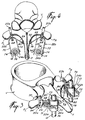
- Fig. 7 is a fragmentary perspective view showing a modified version of the detail shown in Figs. 5 and 6.
-
- An
internal brace system 10 is shown in Figs. 1 and 2 in its assembled condition. Theinternal brace system 10 would be sold as a kit for implanting within the human body in a surgical procedure for the purpose of correcting a spinal column disorder involving a lateral curve with some torsion or rotation. It has been found that in patients suffering from scoliosis, that the vertebrae in the curved portion may be rotated horizontally due to torsional forces acting thereon. Theinternal brace system 10 would, as will be seen, retain the individual vertebra in a reoriented position approximating their position in a normal spinal column. - The kit making up the
internal brace system 10 would include a pair ofrods rods rods bars rods rods - The spinal column S to which the internal brace system is to be applied includes a number of vertebrae Va....Vn, each including, for the purposes of this description transverse processes PL and PR and a spinous process T. The vertebrae Va....Vn would, in a patient suffering from scoliosis be curved laterally out of a longitudinal plane of the spine S and it would be necessary to rotate and realign each vertebra in longitudinal alignment and to be harnessed to the
internal brace system 10. - In the present embodiment, the
internal brace system 10 includes, a plurality ofcuffs 20 which can be mounted to individual transverse processes P and tie means in the form ofU-shape tie members 22 connecting thecuffs 20 in an articulated manner toindividual sleeves 24 slidably mounted on therods - Referring now to Figs. 3 and 4, the vertebra harness will be described in more detail. As shown in Figs. 3 and 4, there is a
cuff 20a which is clasped to the transverse process PL and anidentical cuff 20b clasps to the transverse process PR. The U-shaped tie 22a connects thecuff 20a to the sleeve 24a onrod 12. Likewise the U-shapetie member 22b connects thecuff 20b to thesleeve 24b onrod 14. - The
cuff 20 is shown, in Figs. 5 and 6, in detail and includes abase member 26 and a pair ofarms hinges locking pin 36 is hinged to thearm 30 by means ofhinge 38. Thepin 36 is threaded and adapted to receive anut 40. Thenut 40 locks the pin to thebase 26 as shown in Figs. 5 and 6. Accordingly thecuff 20 will be able to fit any irregularity or size of transverse process because of the particular adjustable structure shown. Thebase 26 also has a jaw 42 to receive thebight portion 68 of the U-shapedtie 22. A lockingbolt 44 will close the jaw 42 once thebight 68 has been mounted in the jaw 42. - The
tie member 22 is best shown in Figs. 3 and 4 and includes abight 68 with a pair ofparallel arms arms slots sleeve 24. Theslots arms tie member 22 allows articulation and a degree of lateral movement to the vertebra V. However, since both transverse processes PL and PR are likewise anchored to therespective rods - It is also believed that the structure will retain the vertebra in its assumed position approximating a normal position of the vertebra in a correct spinal column.
- In order to prevent the
cuffs anchor tube 78 will be provided on the spinous process T. In one embodiment a bore is drilled through the spinous process T and theanchor tube 78 is fitted therein. Lockingnuts tube 78 and a flexible cord of synthetic material such as nylon is attached to eachcuff cord 84 will prevent thecuffs - The
internal brace system 10 is selected to be long enough to be coextensive with the portion of the spinal column S which is to be corrected. The ends of therods heads 67 of square cross-section as shown, for instance, in Fig. 7. The square heads 67 of therods cuff 46 in Fig. 7 includes the articulatedarms pin 58 andnut 60. However, thebase 48 will also include a tube 64 (rigid tie means) having a bore or opening 66 which has a square cross-section similar to the square cross-section of thehead 67 of therod 12. - The base 48 will have a length which is selected depending on the distance of the
internal brace system 10 from a correct vertebra as shown in Fig. 2. Likewise, at the other end of therod 12, a similar cuff 46a will be locked to a transverse process PL of a correct vertebra. Thus, the internalbrace assembly system 10 will be locked at each end to a correct vertebra, in this case the vertebra Vb and Vn while the vertebrae to be realigned are harnessed by means of thecuffs tie members 22 connected on the slidingsleeve 24a and 24b. - The provision of the sliding
sleeves 24 andflexible ties 22 will allow limited movement of each vertebra and will allow the loads to be carried by the realigned spinal column S so as to simulate a more normal spinal column. The sleeve may have apolyethylene liner 76 to reduce friction. - The
bars rods suitable set screws 13 thebars rods - When the
internal brace system 10 is implanted, it is necessary to sever certain ligaments particularly between the spinous processes. It has been contemplated to attach biodegradable polymer ligaments between the spinous processes and probably between respective transverse processes. The polymer material, in one example, could include from 0% to 30% hydroxyvalerate and from 100% to 70% poly-hydroxybutyrate. Ligaments of this material would slowly degrade while natural ligaments are regenerated. The material and its uses are described in G.B. Patent 1034 123 in the name of W. R. Grace & Co.
Claims (11)
- An internal brace system (10) comprising : a pair of implantable rods (12, 14) for mounting on either side of a spinal column coextensive wit a portion of the spinal column to be treated; first means (16, 18) for rigidly connecting said rods together in a spaced-apart parallel arrangement to provide a unitary internal brace structure; and first tie means (22a, 22b), characterised by pairs of anchor means (20a, 20b), each of said pairs of anchor means suitable for being associated with a corresponding one of a plurality of selected vertebrae, each of said anchor means of each of said pairs of anchor means (20a, 20b) suitable for being disposed on respective transverse processes of said corresponding one of said plurality of selected vertebrae in the portion of the spinal column to be treated; said first tie means (22a, 22b) extending from each of said anchor means (20a, 20b) to respective ones of second connecting means (24a, 24b) on a respective rod (12, 14) of the internal brace structure on either side of the spinal column, said first tie means (22a, 22b) allowing articulation and lateral movement of said corresponding one of said plurality of selected vertebrae while retaining said corresponding one of said plurality of selected vertebrae in a predetermined location relative to the internal brace structure and against torsional forces applied through the spinal column.
- An internal brace system (10) as defined in claim 1, wherein each of said anchor means (20a, 20b) are in the form of a cuff mounted on said respective transverse process and the first displaceable tie means (22a, 22b) is articulately connected to each cuff.
- An internal brace system (10) as defined in claim 2, wherein each cuff (20a, 20b) includes a base portion (26) and at least a pair of articulated arms (28, 30) extending from the base portion (26) and adapted to be locked forming a loop with adjustable locking means (36, 40) to vary the size and shape of the loop to accommodate the respective transverse process of said corresponding one of said plurality of vertebrae.
- An internal brace system (10) as defined in claim 2, further comprising second anchor means (78) attached to a spinous process of at least one of the plurality of selected vertebrae and second tie means (84) extending between the cuffs associated with the at least one of the plurality of selected vertebrae and the second anchor means (78) for preventing said cuffs associated with the at least one of the plurality of selected vertebrae from slipping off the respective transverse processes.
- An internal brace system (10) as defined in any one of claims 1 to 4, wherein the rods (12, 14) are made of titanium.
- An internal brace system (10) as defined in any one of claims 1 to 5, wherein the second connecting means (24a, 24b) on the rods are in the form of sleeves adapted to slide on the rods with each separate sleeve corresponding to a respective first tie means (22a, 22b) extending from each anchor means (20a, 20b) on said respective transverse process of said corresponding one of said plurality of said selected vertebrae.
- An internal brace system (10) as defined in claim 6, wherein each of said respective first tie means (22a, 22b) includes a rigid U-shaped bracket having a bight portion (68) adapted to be engaged in an articulate manner with said cuff, the U-shaped bracket including a pair of parallel arms (70, 72) extending from the bight and each of said arms including an elongated slot (71, 73) adapted to be engaged on a cap pin (74) on respective portions of each of said separate sleeves (24a, 24b) such that the brace system (10) can slide relative to said separate sleeves.
- An internal brace system (10) as defined in any one of claims 4 to 7, wherein the second tie means (84) is in the form of a flexible, strong cord, the second anchor means (78) for the spinous process includes a tube which passes trough the spinous process and means (80, 82) for locking the tube to the spinous process, and the flexible cord extends through the tube such that each end of the flexible cord is connectable to one of said cuffs (20a, 20b) associated with at least one of the plurality of selected vertebrae.
- An internal brace system (10) as defined in any one of claims 1 to 8, wherein the first means (16, 18) for rigidly connecting the rods (12, 14) is in the form of detachable bars extending between the rods at each end of the rods thereof and for providing a rigid connection between each of end cuffs (46a, 46b) associated with each of said plurality of selected vertebrae corresponding to the ends of the rods and the rods.
- An internal brace system (10) as defined in claim 9, further comprising locking set screws (13) and wherein the ends of the rods have a square cross section (67), said first means (16, 18) for rigidly connecting said rods together includes detachable bars each having bores with a cross section approximately the same as the square cross section of the rods and said locking set screws (15) lock the rods and the detachable bars in a unitary structure.
- An internal brace system as defined in any one of claims 1 to 10, wherein the first tie means (22a, 22b) is articulated.
Applications Claiming Priority (3)
| Application Number | Priority Date | Filing Date | Title |
|---|---|---|---|
| US15919 | 1993-02-10 | ||
| US08/015,919 US5413576A (en) | 1993-02-10 | 1993-02-10 | Apparatus for treating spinal disorder |
| PCT/CA1994/000068 WO1994017736A1 (en) | 1993-02-10 | 1994-02-09 | Apparatus for treating spinal disorder |
Publications (2)
| Publication Number | Publication Date |
|---|---|
| EP0683644A1 EP0683644A1 (en) | 1995-11-29 |
| EP0683644B1 true EP0683644B1 (en) | 2000-06-28 |
Family
ID=21774347
Family Applications (1)
| Application Number | Title | Priority Date | Filing Date |
|---|---|---|---|
| EP94906114A Expired - Lifetime EP0683644B1 (en) | 1993-02-10 | 1994-02-09 | Apparatus for treating spinal disorder |
Country Status (9)
| Country | Link |
|---|---|
| US (1) | US5413576A (en) |
| EP (1) | EP0683644B1 (en) |
| JP (1) | JPH08509389A (en) |
| AT (1) | ATE194063T1 (en) |
| AU (1) | AU5997794A (en) |
| DE (1) | DE69425046T2 (en) |
| DK (1) | DK0683644T3 (en) |
| ES (1) | ES2149866T3 (en) |
| WO (1) | WO1994017736A1 (en) |
Cited By (7)
| Publication number | Priority date | Publication date | Assignee | Title |
|---|---|---|---|---|
| US9241739B2 (en) | 2008-09-12 | 2016-01-26 | DePuy Synthes Products, Inc. | Spinal stabilizing and guiding fixation system |
| US9848918B2 (en) | 2005-11-21 | 2017-12-26 | DePuy Synthes Products, Inc. | Polyaxial bone anchors with increased angulation |
| US10105163B2 (en) | 2009-04-15 | 2018-10-23 | DePuy Synthes Products, Inc. | Revision connector for spinal constructs |
| US10136923B2 (en) | 2007-07-20 | 2018-11-27 | DePuy Synthes Products, Inc. | Polyaxial bone fixation element |
| US10154859B2 (en) | 2008-09-29 | 2018-12-18 | DePuy Synthes Products, Inc. | Polyaxial bottom-loading screw and rod assembly |
| US11006978B2 (en) | 2009-06-17 | 2021-05-18 | DePuy Synthes Products, Inc. | Revision connector for spinal constructs |
| US11484348B2 (en) | 2008-11-03 | 2022-11-01 | DePuy Synthes Products, Inc. | Uni-planer bone fixation assembly |
Families Citing this family (150)
| Publication number | Priority date | Publication date | Assignee | Title |
|---|---|---|---|---|
| US5630816A (en) * | 1995-05-01 | 1997-05-20 | Kambin; Parviz | Double barrel spinal fixation system and method |
| NZ272994A (en) * | 1995-09-12 | 2001-06-29 | C G Surgical Ltd | Spinal prosthesis device which stabilises lamina after laminoplasty |
| US6352537B1 (en) | 1998-09-17 | 2002-03-05 | Electro-Biology, Inc. | Method and apparatus for spinal fixation |
| FR2783411B1 (en) * | 1998-09-18 | 2000-12-01 | Eurosurgical | POSTERIOR SPINAL OSTEOSYNTHESIS DEVICE |
| CA2591678C (en) * | 1999-03-07 | 2008-05-20 | Active Implants Corporation | Method and apparatus for computerized surgery |
| US6974478B2 (en) * | 1999-10-22 | 2005-12-13 | Archus Orthopedics, Inc. | Prostheses, systems and methods for replacement of natural facet joints with artificial facet joint surfaces |
| US20050261770A1 (en) * | 2004-04-22 | 2005-11-24 | Kuiper Mark K | Crossbar spinal prosthesis having a modular design and related implantation methods |
| EP1854433B1 (en) * | 1999-10-22 | 2010-05-12 | FSI Acquisition Sub, LLC | Facet arthroplasty devices |
| US7674293B2 (en) | 2004-04-22 | 2010-03-09 | Facet Solutions, Inc. | Crossbar spinal prosthesis having a modular design and related implantation methods |
| US8187303B2 (en) | 2004-04-22 | 2012-05-29 | Gmedelaware 2 Llc | Anti-rotation fixation element for spinal prostheses |
| US20050027361A1 (en) * | 1999-10-22 | 2005-02-03 | Reiley Mark A. | Facet arthroplasty devices and methods |
| US7691145B2 (en) * | 1999-10-22 | 2010-04-06 | Facet Solutions, Inc. | Prostheses, systems and methods for replacement of natural facet joints with artificial facet joint surfaces |
| US6811567B2 (en) * | 1999-10-22 | 2004-11-02 | Archus Orthopedics Inc. | Facet arthroplasty devices and methods |
| DE19957332B4 (en) * | 1999-11-29 | 2004-11-11 | Bernd Schäfer | cross-connector |
| US6514255B1 (en) | 2000-02-25 | 2003-02-04 | Bret Ferree | Sublaminar spinal fixation apparatus |
| FR2812186B1 (en) * | 2000-07-25 | 2003-02-28 | Spine Next Sa | FLEXIBLE CONNECTION PIECE FOR SPINAL STABILIZATION |
| FR2812185B1 (en) | 2000-07-25 | 2003-02-28 | Spine Next Sa | SEMI-RIGID CONNECTION PIECE FOR RACHIS STABILIZATION |
| US6554831B1 (en) | 2000-09-01 | 2003-04-29 | Hopital Sainte-Justine | Mobile dynamic system for treating spinal disorder |
| FR2842724B1 (en) * | 2002-07-23 | 2005-05-27 | Spine Next Sa | VERTEBRAL FASTENING SYSTEM |
| AU2003265597A1 (en) * | 2002-08-23 | 2004-03-11 | Paul C. Mcafee | Metal-backed uhmpe rod sleeve system preserving spinal motion |
| US7011659B2 (en) | 2003-03-17 | 2006-03-14 | Lewis Edward L | Connector for attaching an alignment rod to a bone structure |
| US20060293660A1 (en) * | 2005-06-03 | 2006-12-28 | Lewis Edward L | Connector for attaching an alignment rod to a bone structure |
| IL155222A0 (en) * | 2003-04-03 | 2003-11-23 | Hadasit Med Res Service | An implant for treating idiopathic scoliosis and a method for using the same |
| US7608104B2 (en) * | 2003-05-14 | 2009-10-27 | Archus Orthopedics, Inc. | Prostheses, tools and methods for replacement of natural facet joints with artifical facet joint surfaces |
| US20040230304A1 (en) | 2003-05-14 | 2004-11-18 | Archus Orthopedics Inc. | Prostheses, tools and methods for replacement of natural facet joints with artifical facet joint surfaces |
| US6986771B2 (en) * | 2003-05-23 | 2006-01-17 | Globus Medical, Inc. | Spine stabilization system |
| US7074238B2 (en) | 2003-07-08 | 2006-07-11 | Archus Orthopedics, Inc. | Prostheses, tools and methods for replacement of natural facet joints with artificial facet joint surfaces |
| US7763052B2 (en) * | 2003-12-05 | 2010-07-27 | N Spine, Inc. | Method and apparatus for flexible fixation of a spine |
| US8979900B2 (en) | 2003-09-24 | 2015-03-17 | DePuy Synthes Products, LLC | Spinal stabilization device |
| US7815665B2 (en) * | 2003-09-24 | 2010-10-19 | N Spine, Inc. | Adjustable spinal stabilization system |
| US20050065516A1 (en) * | 2003-09-24 | 2005-03-24 | Tae-Ahn Jahng | Method and apparatus for flexible fixation of a spine |
| US20050203513A1 (en) * | 2003-09-24 | 2005-09-15 | Tae-Ahn Jahng | Spinal stabilization device |
| US20050131406A1 (en) | 2003-12-15 | 2005-06-16 | Archus Orthopedics, Inc. | Polyaxial adjustment of facet joint prostheses |
| US8029548B2 (en) * | 2008-05-05 | 2011-10-04 | Warsaw Orthopedic, Inc. | Flexible spinal stabilization element and system |
| US7846183B2 (en) | 2004-02-06 | 2010-12-07 | Spinal Elements, Inc. | Vertebral facet joint prosthesis and method of fixation |
| US7406775B2 (en) | 2004-04-22 | 2008-08-05 | Archus Orthopedics, Inc. | Implantable orthopedic device component selection instrument and methods |
| US9504583B2 (en) | 2004-06-10 | 2016-11-29 | Spinal Elements, Inc. | Implant and method for facet immobilization |
| WO2006017641A2 (en) * | 2004-08-03 | 2006-02-16 | Vertech Innovations, L.L.C. | Spinous process reinforcement device and method |
| US8114158B2 (en) | 2004-08-03 | 2012-02-14 | Kspine, Inc. | Facet device and method |
| US20060036259A1 (en) * | 2004-08-03 | 2006-02-16 | Carl Allen L | Spine treatment devices and methods |
| US20060036324A1 (en) | 2004-08-03 | 2006-02-16 | Dan Sachs | Adjustable spinal implant device and method |
| US7854752B2 (en) | 2004-08-09 | 2010-12-21 | Theken Spine, Llc | System and method for dynamic skeletal stabilization |
| TW200612860A (en) * | 2004-08-09 | 2006-05-01 | Innovative Spinal Technologies | System and method for dynamic skeletal stabilization |
| US20060041311A1 (en) * | 2004-08-18 | 2006-02-23 | Mcleer Thomas J | Devices and methods for treating facet joints |
| AU2005277363A1 (en) | 2004-08-18 | 2006-03-02 | Fsi Acquisition Sub, Llc | Adjacent level facet arthroplasty devices, spine stabilization systems, and methods |
| US20060085075A1 (en) * | 2004-10-04 | 2006-04-20 | Archus Orthopedics, Inc. | Polymeric joint complex and methods of use |
| DE102004048938B4 (en) * | 2004-10-07 | 2015-04-02 | Synthes Gmbh | Device for the dynamic stabilization of vertebral bodies |
| US8241330B2 (en) | 2007-01-11 | 2012-08-14 | Lanx, Inc. | Spinous process implants and associated methods |
| AU2005307005A1 (en) * | 2004-10-25 | 2006-05-26 | Fsi Acquisition Sub, Llc | Crossbar spinal prosthesis having a modular design and systems for treating spinal pathologies |
| US9055981B2 (en) | 2004-10-25 | 2015-06-16 | Lanx, Inc. | Spinal implants and methods |
| WO2006058221A2 (en) | 2004-11-24 | 2006-06-01 | Abdou Samy M | Devices and methods for inter-vertebral orthopedic device placement |
| US7896905B2 (en) * | 2005-02-09 | 2011-03-01 | David Lee | Bone fixation apparatus |
| US20060229607A1 (en) * | 2005-03-16 | 2006-10-12 | Sdgi Holdings, Inc. | Systems, kits and methods for treatment of the spinal column using elongate support members |
| US8496686B2 (en) * | 2005-03-22 | 2013-07-30 | Gmedelaware 2 Llc | Minimally invasive spine restoration systems, devices, methods and kits |
| CN103479419B (en) | 2005-04-08 | 2017-04-12 | 帕拉迪格脊骨有限责任公司 | Interspinous vertebral and lumbosacral stabilization devices and methods of use |
| US7666208B1 (en) | 2005-04-29 | 2010-02-23 | Asfora Ip, Llc | Posterior cervical vertebral stabilizing system |
| US7695496B2 (en) * | 2005-06-10 | 2010-04-13 | Depuy Spine, Inc. | Posterior dynamic stabilization Y-device |
| FR2890850B1 (en) * | 2005-09-20 | 2009-04-17 | Abbott Spine Sa | VERTEBRAL FASTENING SYSTEM |
| FR2890851B1 (en) | 2005-09-21 | 2008-06-20 | Abbott Spine Sa | ANCILLARY TO TENSION A FLEXIBLE LINK. |
| US20080287959A1 (en) * | 2005-09-26 | 2008-11-20 | Archus Orthopedics, Inc. | Measurement and trialing system and methods for orthopedic device component selection |
| ES2482790T3 (en) | 2005-09-27 | 2014-08-04 | Paradigm Spine, Llc | Interspinal vertebral stabilization devices |
| US7927359B2 (en) | 2005-10-06 | 2011-04-19 | Paradigm Spine, Llc | Polyaxial screw |
| GB0521585D0 (en) * | 2005-10-22 | 2005-11-30 | Depuy Int Ltd | A spinal support rod |
| GB0521582D0 (en) * | 2005-10-22 | 2005-11-30 | Depuy Int Ltd | An implant for supporting a spinal column |
| US8357181B2 (en) | 2005-10-27 | 2013-01-22 | Warsaw Orthopedic, Inc. | Intervertebral prosthetic device for spinal stabilization and method of implanting same |
| US7699873B2 (en) * | 2005-11-23 | 2010-04-20 | Warsaw Orthopedic, Inc. | Spinous process anchoring systems and methods |
| EP1968466A2 (en) * | 2005-12-19 | 2008-09-17 | M. S. Abdou | Devices for inter-vertebral orthopedic device placement |
| WO2007126428A2 (en) | 2005-12-20 | 2007-11-08 | Archus Orthopedics, Inc. | Arthroplasty revision system and method |
| GB0600662D0 (en) * | 2006-01-13 | 2006-02-22 | Depuy Int Ltd | Spinal support rod kit |
| US8348952B2 (en) * | 2006-01-26 | 2013-01-08 | Depuy International Ltd. | System and method for cooling a spinal correction device comprising a shape memory material for corrective spinal surgery |
| US20070233068A1 (en) * | 2006-02-22 | 2007-10-04 | Sdgi Holdings, Inc. | Intervertebral prosthetic assembly for spinal stabilization and method of implanting same |
| US8025681B2 (en) * | 2006-03-29 | 2011-09-27 | Theken Spine, Llc | Dynamic motion spinal stabilization system |
| US20070288012A1 (en) * | 2006-04-21 | 2007-12-13 | Dennis Colleran | Dynamic motion spinal stabilization system and device |
| US8092536B2 (en) * | 2006-05-24 | 2012-01-10 | Disc Dynamics, Inc. | Retention structure for in situ formation of an intervertebral prosthesis |
| US20070276491A1 (en) * | 2006-05-24 | 2007-11-29 | Disc Dynamics, Inc. | Mold assembly for intervertebral prosthesis |
| US8449576B2 (en) * | 2006-06-28 | 2013-05-28 | DePuy Synthes Products, LLC | Dynamic fixation system |
| US8303630B2 (en) * | 2006-07-27 | 2012-11-06 | Samy Abdou | Devices and methods for the minimally invasive treatment of spinal stenosis |
| WO2008019397A2 (en) | 2006-08-11 | 2008-02-14 | Archus Orthopedics, Inc. | Angled washer polyaxial connection for dynamic spine prosthesis |
| US8317830B2 (en) * | 2006-08-29 | 2012-11-27 | Warsaw Orthopedic, Inc. | Orthopaedic screw system with linear motion |
| EP2047813A1 (en) | 2007-10-11 | 2009-04-15 | Abbott Spine | Bone fixing system and method of use |
| US20080119845A1 (en) * | 2006-09-25 | 2008-05-22 | Archus Orthopedics, Inc. | Facet replacement device removal and revision systems and methods |
| US20080161856A1 (en) * | 2006-10-06 | 2008-07-03 | Mingyan Liu | Spinal stabilization system |
| US9265532B2 (en) | 2007-01-11 | 2016-02-23 | Lanx, Inc. | Interspinous implants and methods |
| US7931676B2 (en) * | 2007-01-18 | 2011-04-26 | Warsaw Orthopedic, Inc. | Vertebral stabilizer |
| US20080177326A1 (en) * | 2007-01-19 | 2008-07-24 | Matthew Thompson | Orthosis to correct spinal deformities |
| US8435268B2 (en) * | 2007-01-19 | 2013-05-07 | Reduction Technologies, Inc. | Systems, devices and methods for the correction of spinal deformities |
| US8029547B2 (en) * | 2007-01-30 | 2011-10-04 | Warsaw Orthopedic, Inc. | Dynamic spinal stabilization assembly with sliding collars |
| US8109975B2 (en) * | 2007-01-30 | 2012-02-07 | Warsaw Orthopedic, Inc. | Collar bore configuration for dynamic spinal stabilization assembly |
| US20080195153A1 (en) * | 2007-02-08 | 2008-08-14 | Matthew Thompson | Dynamic spinal deformity correction |
| EP2813190B1 (en) | 2007-02-22 | 2017-04-26 | Spinal Elements, Inc. | Vertebral facet joint drill |
| US8992533B2 (en) | 2007-02-22 | 2015-03-31 | Spinal Elements, Inc. | Vertebral facet joint drill and method of use |
| AU2013205419B2 (en) * | 2007-06-06 | 2015-10-08 | K2M, Inc. | Medical Device and Method to Correct Deformity |
| EP2155086B1 (en) * | 2007-06-06 | 2016-05-04 | K2M, Inc. | Medical device to correct deformity |
| US9204908B2 (en) * | 2007-07-26 | 2015-12-08 | Dynamic Spine, Llc | Segmental orthopedic device for spinal elongation and for treatment of scoliosis |
| CA2694437C (en) * | 2007-07-26 | 2016-09-06 | Glenn R. Buttermann | Segmental orthopedic device for spinal elongation and for treatment of scoliosis |
| EP2178451A2 (en) * | 2007-08-07 | 2010-04-28 | Synthes GmbH | Dynamic cable system |
| US8128635B2 (en) * | 2007-10-23 | 2012-03-06 | Zimmer Spine S.A.S. | Bone fixation tensioning tool and method |
| EP2052689B1 (en) * | 2007-10-23 | 2011-12-14 | Zimmer Spine | Fixing devices and stabilization systems using said fixing devices |
| GB0720762D0 (en) | 2007-10-24 | 2007-12-05 | Depuy Spine Sorl | Assembly for orthopaedic surgery |
| US20090264933A1 (en) * | 2008-04-22 | 2009-10-22 | Warsaw Orthopedic, Inc. | Anchors for securing a rod to a vertebral member |
| ATE515239T1 (en) * | 2008-04-24 | 2011-07-15 | Zimmer Spine | SYSTEM FOR STABILIZING AT LEAST ONE SECTION OF THE SPINE |
| ES2378142T3 (en) * | 2008-05-20 | 2012-04-09 | Zimmer Spine | System to stabilize at least three vertebrae |
| US20100049252A1 (en) * | 2008-08-21 | 2010-02-25 | Southern Spine, Llc | Transverse Connector Device for Extending an Existing Spinal Fixation System |
| US8828058B2 (en) | 2008-11-11 | 2014-09-09 | Kspine, Inc. | Growth directed vertebral fixation system with distractible connector(s) and apical control |
| EP2373236B1 (en) * | 2008-12-17 | 2014-05-21 | Synthes GmbH | Posterior spine dynamic stabilizer |
| FR2940040B1 (en) * | 2008-12-19 | 2011-01-21 | Clariance | HINGE FASTENING SYSTEM FOR SPINAL OSTEOSYNTHESIS DEVICE. |
| US20110137345A1 (en) * | 2009-03-18 | 2011-06-09 | Caleb Stoll | Posterior lumbar fusion |
| US8357183B2 (en) | 2009-03-26 | 2013-01-22 | Kspine, Inc. | Semi-constrained anchoring system |
| EP2413825A4 (en) | 2009-03-31 | 2013-12-11 | Lanx Inc | Spinous process implants and associated methods |
| US8419772B2 (en) * | 2009-06-08 | 2013-04-16 | Reduction Technologies, Inc. | Systems, methods and devices for correcting spinal deformities |
| US9168071B2 (en) | 2009-09-15 | 2015-10-27 | K2M, Inc. | Growth modulation system |
| US8764806B2 (en) | 2009-12-07 | 2014-07-01 | Samy Abdou | Devices and methods for minimally invasive spinal stabilization and instrumentation |
| AU2011264818B2 (en) | 2010-06-10 | 2015-06-18 | Globus Medical, Inc. | Low-profile, uniplanar bone screw |
| US8920471B2 (en) | 2010-07-12 | 2014-12-30 | K2M, Inc. | Transverse connector |
| US9271765B2 (en) | 2011-02-24 | 2016-03-01 | Spinal Elements, Inc. | Vertebral facet joint fusion implant and method for fusion |
| US8740949B2 (en) | 2011-02-24 | 2014-06-03 | Spinal Elements, Inc. | Methods and apparatus for stabilizing bone |
| USD724733S1 (en) | 2011-02-24 | 2015-03-17 | Spinal Elements, Inc. | Interbody bone implant |
| US9333009B2 (en) | 2011-06-03 | 2016-05-10 | K2M, Inc. | Spinal correction system actuators |
| US8845728B1 (en) | 2011-09-23 | 2014-09-30 | Samy Abdou | Spinal fixation devices and methods of use |
| US9084635B2 (en) * | 2011-10-07 | 2015-07-21 | Regents Of The University Of Minnesota | Intraoperative spinal stabilization |
| US11812923B2 (en) | 2011-10-07 | 2023-11-14 | Alan Villavicencio | Spinal fixation device |
| USD739935S1 (en) | 2011-10-26 | 2015-09-29 | Spinal Elements, Inc. | Interbody bone implant |
| US9468468B2 (en) | 2011-11-16 | 2016-10-18 | K2M, Inc. | Transverse connector for spinal stabilization system |
| US9451987B2 (en) | 2011-11-16 | 2016-09-27 | K2M, Inc. | System and method for spinal correction |
| WO2014172632A2 (en) | 2011-11-16 | 2014-10-23 | Kspine, Inc. | Spinal correction and secondary stabilization |
| US9468469B2 (en) | 2011-11-16 | 2016-10-18 | K2M, Inc. | Transverse coupler adjuster spinal correction systems and methods |
| US8920472B2 (en) | 2011-11-16 | 2014-12-30 | Kspine, Inc. | Spinal correction and secondary stabilization |
| US20130226240A1 (en) | 2012-02-22 | 2013-08-29 | Samy Abdou | Spinous process fixation devices and methods of use |
| US9198767B2 (en) | 2012-08-28 | 2015-12-01 | Samy Abdou | Devices and methods for spinal stabilization and instrumentation |
| US9320617B2 (en) | 2012-10-22 | 2016-04-26 | Cogent Spine, LLC | Devices and methods for spinal stabilization and instrumentation |
| USD765853S1 (en) | 2013-03-14 | 2016-09-06 | Spinal Elements, Inc. | Flexible elongate member with a portion configured to receive a bone anchor |
| US9421044B2 (en) | 2013-03-14 | 2016-08-23 | Spinal Elements, Inc. | Apparatus for bone stabilization and distraction and methods of use |
| US9820784B2 (en) | 2013-03-14 | 2017-11-21 | Spinal Elements, Inc. | Apparatus for spinal fixation and methods of use |
| US9468471B2 (en) | 2013-09-17 | 2016-10-18 | K2M, Inc. | Transverse coupler adjuster spinal correction systems and methods |
| US9456855B2 (en) | 2013-09-27 | 2016-10-04 | Spinal Elements, Inc. | Method of placing an implant between bone portions |
| US9839450B2 (en) | 2013-09-27 | 2017-12-12 | Spinal Elements, Inc. | Device and method for reinforcement of a facet |
| US9486252B2 (en) * | 2014-01-09 | 2016-11-08 | Warsaw Orthopedic, Inc. | Spinal correction system and method |
| WO2016044432A1 (en) | 2014-09-17 | 2016-03-24 | Spinal Elements, Inc. | Flexible fastening band connector |
| JP2018502693A (en) | 2015-01-27 | 2018-02-01 | スパイナル・エレメンツ・インコーポレーテッド | Facet joint implant |
| US10857003B1 (en) | 2015-10-14 | 2020-12-08 | Samy Abdou | Devices and methods for vertebral stabilization |
| US10973648B1 (en) | 2016-10-25 | 2021-04-13 | Samy Abdou | Devices and methods for vertebral bone realignment |
| US10744000B1 (en) | 2016-10-25 | 2020-08-18 | Samy Abdou | Devices and methods for vertebral bone realignment |
| US11071569B2 (en) | 2017-08-10 | 2021-07-27 | Ortho Development Corporation | Nesting tether clamping assemblies and related methods and apparatus |
| US11051857B2 (en) | 2017-08-10 | 2021-07-06 | Ortho Development Corporation | Tether clamping assemblies and related methods and apparatus |
| US11179248B2 (en) | 2018-10-02 | 2021-11-23 | Samy Abdou | Devices and methods for spinal implantation |
| US10869696B2 (en) | 2019-01-30 | 2020-12-22 | Medos International Sarl | Surgical device for spinal fixation |
| US11457959B2 (en) | 2019-05-22 | 2022-10-04 | Spinal Elements, Inc. | Bone tie and bone tie inserter |
| AU2020278453A1 (en) | 2019-05-22 | 2022-01-20 | Spinal Elements, Inc. | Bone tie and bone tie inserter |
| US11819255B2 (en) | 2019-10-07 | 2023-11-21 | Ortho Development Corporation | Tether tensioning instrumentation and related methods |
| WO2021163313A1 (en) | 2020-02-14 | 2021-08-19 | Spinal Elements, Inc. | Bone tie methods |
Family Cites Families (15)
| Publication number | Priority date | Publication date | Assignee | Title |
|---|---|---|---|---|
| US2774350A (en) * | 1952-09-08 | 1956-12-18 | Jr Carl S Cleveland | Spinal clamp or splint |
| US3225766A (en) * | 1962-03-26 | 1965-12-28 | Grace W R & Co | Method of making absorbable surgical sutures from poly beta hydroxy acids |
| FR2244446A1 (en) * | 1973-09-21 | 1975-04-18 | Cotrel Yves | Traction device for scoliosis - tensioner rod clamped across vert. rods tensions vertebrae under max stress |
| GB1551706A (en) * | 1975-04-28 | 1979-08-30 | Downs Surgical Ltd | Surgical implant |
| DE3032237C2 (en) * | 1980-08-27 | 1983-11-10 | Fraunhofer-Gesellschaft zur Förderung der angewandten Forschung e.V., 8000 München | Scoliosis treatment implant |
| CA1158402A (en) * | 1981-04-06 | 1983-12-13 | Kevin A. Bobechko | Self-adjusting spinal scoliosis fusion hook |
| FR2545350B1 (en) * | 1983-05-04 | 1985-08-23 | Cotrel Yves | DEVICE FOR SHRINKAGE OF THE RACHIS |
| US4573454A (en) * | 1984-05-17 | 1986-03-04 | Hoffman Gregory A | Spinal fixation apparatus |
| US4875471A (en) * | 1987-02-20 | 1989-10-24 | Codespi Corporation | Device for correcting deformities of the spine |
| GB8718708D0 (en) * | 1987-08-07 | 1987-09-16 | Mehdian S M H | Apparatus for treatment of spinal disorders |
| SU1544409A1 (en) * | 1988-07-20 | 1990-02-23 | Ставропольский государственный медицинский институт | Vertebral column corrector |
| GB8825909D0 (en) * | 1988-11-04 | 1988-12-07 | Showell A W Sugicraft Ltd | Pedicle engaging means |
| US5084049A (en) * | 1989-02-08 | 1992-01-28 | Acromed Corporation | Transverse connector for spinal column corrective devices |
| FR2645427A1 (en) * | 1989-04-11 | 1990-10-12 | Cotrel Yves | Transverse fixing bar for spinal osteosynthesis device |
| US5133716A (en) * | 1990-11-07 | 1992-07-28 | Codespi Corporation | Device for correction of spinal deformities |
-
1993
- 1993-02-10 US US08/015,919 patent/US5413576A/en not_active Expired - Lifetime
-
1994
- 1994-02-09 DE DE69425046T patent/DE69425046T2/en not_active Expired - Lifetime
- 1994-02-09 WO PCT/CA1994/000068 patent/WO1994017736A1/en active IP Right Grant
- 1994-02-09 JP JP6517481A patent/JPH08509389A/en active Pending
- 1994-02-09 AU AU59977/94A patent/AU5997794A/en not_active Abandoned
- 1994-02-09 DK DK94906114T patent/DK0683644T3/en active
- 1994-02-09 EP EP94906114A patent/EP0683644B1/en not_active Expired - Lifetime
- 1994-02-09 AT AT94906114T patent/ATE194063T1/en not_active IP Right Cessation
- 1994-02-09 ES ES94906114T patent/ES2149866T3/en not_active Expired - Lifetime
Cited By (17)
| Publication number | Priority date | Publication date | Assignee | Title |
|---|---|---|---|---|
| US10595908B2 (en) | 2005-11-21 | 2020-03-24 | DePuy Sythes Products, Inc. | Polaxial bone anchors with increased angulation |
| US9848918B2 (en) | 2005-11-21 | 2017-12-26 | DePuy Synthes Products, Inc. | Polyaxial bone anchors with increased angulation |
| US11432850B2 (en) | 2005-11-21 | 2022-09-06 | DePuy Synthes Products, Inc. | Polyaxial bone anchors with increased angulation |
| US10898234B2 (en) | 2007-07-20 | 2021-01-26 | DePuy Synthes Products, Inc. | Polyaxial bone fixation element |
| US11819247B2 (en) | 2007-07-20 | 2023-11-21 | DePuy Synthes Products, Inc. | Polyaxial bone fixation element |
| US10136923B2 (en) | 2007-07-20 | 2018-11-27 | DePuy Synthes Products, Inc. | Polyaxial bone fixation element |
| US11357550B2 (en) | 2007-07-20 | 2022-06-14 | DePuy Synthes Products, Inc. | Polyaxial bone fixation element |
| US11129648B2 (en) | 2008-09-12 | 2021-09-28 | DePuy Synthes Products, Inc. | Spinal stabilizing and guiding fixation system |
| US11890037B2 (en) | 2008-09-12 | 2024-02-06 | DePuy Synthes Products, Inc. | Spinal stabilizing and guiding fixation system |
| US9241739B2 (en) | 2008-09-12 | 2016-01-26 | DePuy Synthes Products, Inc. | Spinal stabilizing and guiding fixation system |
| US9974571B2 (en) | 2008-09-12 | 2018-05-22 | DePuy Synthes Products, Inc. | Spinal stabilizing and guiding fixation system |
| US10709479B2 (en) | 2008-09-29 | 2020-07-14 | DePuy Synthes Products, Inc. | Polyaxial bottom-loading screw and rod assembly |
| US10154859B2 (en) | 2008-09-29 | 2018-12-18 | DePuy Synthes Products, Inc. | Polyaxial bottom-loading screw and rod assembly |
| US11484348B2 (en) | 2008-11-03 | 2022-11-01 | DePuy Synthes Products, Inc. | Uni-planer bone fixation assembly |
| US11020152B2 (en) | 2009-04-15 | 2021-06-01 | DePuy Synthes Products, Inc. | Revision connector for spinal constructs |
| US10105163B2 (en) | 2009-04-15 | 2018-10-23 | DePuy Synthes Products, Inc. | Revision connector for spinal constructs |
| US11006978B2 (en) | 2009-06-17 | 2021-05-18 | DePuy Synthes Products, Inc. | Revision connector for spinal constructs |
Also Published As
| Publication number | Publication date |
|---|---|
| ES2149866T3 (en) | 2000-11-16 |
| ATE194063T1 (en) | 2000-07-15 |
| DK0683644T3 (en) | 2000-11-13 |
| JPH08509389A (en) | 1996-10-08 |
| EP0683644A1 (en) | 1995-11-29 |
| US5413576A (en) | 1995-05-09 |
| DE69425046D1 (en) | 2000-08-03 |
| WO1994017736A1 (en) | 1994-08-18 |
| DE69425046T2 (en) | 2001-03-22 |
| AU5997794A (en) | 1994-08-29 |
Similar Documents
| Publication | Publication Date | Title |
|---|---|---|
| EP0683644B1 (en) | Apparatus for treating spinal disorder | |
| US20210068869A1 (en) | Growth Directed Vertebral Fixation System With Distractible Connector(s) And Apical Control | |
| US11890037B2 (en) | Spinal stabilizing and guiding fixation system | |
| EP1665994B1 (en) | Mobile dynamic anchoring assembly for connecting an implantable rod with a bone | |
| TWI401059B (en) | Spinal dynamic stabilization device | |
| US6663631B2 (en) | Method and device to correct instability of hinge joints | |
| CA2237268C (en) | Transverse rod connector clip | |
| US5490851A (en) | Method and apparatus for treatment of idiopathic scoliosis | |
| US20130190823A1 (en) | Dynamic spinal deformity correction | |
| US5133716A (en) | Device for correction of spinal deformities | |
| AU707767B2 (en) | Anchoring device for posterior vertebral osteosynthesis | |
| JPH07255739A (en) | Screw for spine of which angle can be changed | |
| US20060084976A1 (en) | Posterior stabilization systems and methods | |
| EP0418387A1 (en) | Device for treatment of curvature of and damage to the spine | |
| AU2005220054A1 (en) | Orthopaedics device and system | |
| WO2010077939A2 (en) | Improved device for spinal fusion | |
| US4664099A (en) | Traction device | |
| CA2155681C (en) | Apparatus for treating spinal disorder | |
| SU1202575A1 (en) | Apparatus for setting and reclination of vertebrae |
Legal Events
| Date | Code | Title | Description |
|---|---|---|---|
| PUAI | Public reference made under article 153(3) epc to a published international application that has entered the european phase |
Free format text: ORIGINAL CODE: 0009012 |
|
| 17P | Request for examination filed |
Effective date: 19950818 |
|
| AK | Designated contracting states |
Kind code of ref document: A1 Designated state(s): AT BE CH DE DK ES FR GB GR IE IT LI LU MC NL PT SE |
|
| RAP1 | Party data changed (applicant data changed or rights of an application transferred) |
Owner name: CENTRE DE RECHERCHE DE L'HOPITAL STE-JUSTINE |
|
| RIN1 | Information on inventor provided before grant (corrected) |
Inventor name: RIVARD, CHARLES-HILAIRE |
|
| 17Q | First examination report despatched |
Effective date: 19981216 |
|
| GRAG | Despatch of communication of intention to grant |
Free format text: ORIGINAL CODE: EPIDOS AGRA |
|
| RAP1 | Party data changed (applicant data changed or rights of an application transferred) |
Owner name: CENTRE DE RECHERCHE DE L'HOPITAL STE-JUSTINE |
|
| RBV | Designated contracting states (corrected) |
Designated state(s): AT BE CH DE DK ES FR GB GR IE IT LI LU MC NL PT SE |
|
| GRAG | Despatch of communication of intention to grant |
Free format text: ORIGINAL CODE: EPIDOS AGRA |
|
| GRAH | Despatch of communication of intention to grant a patent |
Free format text: ORIGINAL CODE: EPIDOS IGRA |
|
| GRAH | Despatch of communication of intention to grant a patent |
Free format text: ORIGINAL CODE: EPIDOS IGRA |
|
| GRAA | (expected) grant |
Free format text: ORIGINAL CODE: 0009210 |
|
| AK | Designated contracting states |
Kind code of ref document: B1 Designated state(s): AT BE CH DE DK ES FR GB GR IE IT LI LU MC NL PT SE |
|
| PG25 | Lapsed in a contracting state [announced via postgrant information from national office to epo] |
Ref country code: NL Free format text: LAPSE BECAUSE OF FAILURE TO SUBMIT A TRANSLATION OF THE DESCRIPTION OR TO PAY THE FEE WITHIN THE PRESCRIBED TIME-LIMIT Effective date: 20000628 Ref country code: GR Free format text: LAPSE BECAUSE OF NON-PAYMENT OF DUE FEES Effective date: 20000628 Ref country code: BE Free format text: LAPSE BECAUSE OF FAILURE TO SUBMIT A TRANSLATION OF THE DESCRIPTION OR TO PAY THE FEE WITHIN THE PRESCRIBED TIME-LIMIT Effective date: 20000628 Ref country code: AT Free format text: LAPSE BECAUSE OF FAILURE TO SUBMIT A TRANSLATION OF THE DESCRIPTION OR TO PAY THE FEE WITHIN THE PRESCRIBED TIME-LIMIT Effective date: 20000628 |
|
| REF | Corresponds to: |
Ref document number: 194063 Country of ref document: AT Date of ref document: 20000715 Kind code of ref document: T |
|
| REG | Reference to a national code |
Ref country code: CH Ref legal event code: EP |
|
| REG | Reference to a national code |
Ref country code: IE Ref legal event code: FG4D |
|
| REF | Corresponds to: |
Ref document number: 69425046 Country of ref document: DE Date of ref document: 20000803 |
|
| ITF | It: translation for a ep patent filed |
Owner name: BARZANO' E ZANARDO MILANO S.P.A. |
|
| PG25 | Lapsed in a contracting state [announced via postgrant information from national office to epo] |
Ref country code: PT Free format text: LAPSE BECAUSE OF FAILURE TO SUBMIT A TRANSLATION OF THE DESCRIPTION OR TO PAY THE FEE WITHIN THE PRESCRIBED TIME-LIMIT Effective date: 20000928 |
|
| ET | Fr: translation filed | ||
| REG | Reference to a national code |
Ref country code: CH Ref legal event code: NV Representative=s name: DR. R.C. SALGO EUROPEAN PATENT ATTORNEY |
|
| REG | Reference to a national code |
Ref country code: DK Ref legal event code: T3 |
|
| REG | Reference to a national code |
Ref country code: ES Ref legal event code: FG2A Ref document number: 2149866 Country of ref document: ES Kind code of ref document: T3 |
|
| NLV1 | Nl: lapsed or annulled due to failure to fulfill the requirements of art. 29p and 29m of the patents act | ||
| PG25 | Lapsed in a contracting state [announced via postgrant information from national office to epo] |
Ref country code: LU Free format text: LAPSE BECAUSE OF NON-PAYMENT OF DUE FEES Effective date: 20010209 Ref country code: IE Free format text: LAPSE BECAUSE OF NON-PAYMENT OF DUE FEES Effective date: 20010209 Ref country code: DK Free format text: LAPSE BECAUSE OF NON-PAYMENT OF DUE FEES Effective date: 20010209 |
|
| PG25 | Lapsed in a contracting state [announced via postgrant information from national office to epo] |
Ref country code: SE Free format text: LAPSE BECAUSE OF NON-PAYMENT OF DUE FEES Effective date: 20010210 |
|
| PG25 | Lapsed in a contracting state [announced via postgrant information from national office to epo] |
Ref country code: MC Free format text: LAPSE BECAUSE OF NON-PAYMENT OF DUE FEES Effective date: 20010228 Ref country code: LI Free format text: LAPSE BECAUSE OF NON-PAYMENT OF DUE FEES Effective date: 20010228 Ref country code: CH Free format text: LAPSE BECAUSE OF NON-PAYMENT OF DUE FEES Effective date: 20010228 |
|
| PLBE | No opposition filed within time limit |
Free format text: ORIGINAL CODE: 0009261 |
|
| STAA | Information on the status of an ep patent application or granted ep patent |
Free format text: STATUS: NO OPPOSITION FILED WITHIN TIME LIMIT |
|
| 26N | No opposition filed | ||
| REG | Reference to a national code |
Ref country code: CH Ref legal event code: PL |
|
| EUG | Se: european patent has lapsed |
Ref document number: 94906114.7 |
|
| REG | Reference to a national code |
Ref country code: DK Ref legal event code: EBP |
|
| REG | Reference to a national code |
Ref country code: IE Ref legal event code: MM4A |
|
| REG | Reference to a national code |
Ref country code: GB Ref legal event code: IF02 |
|
| PGFP | Annual fee paid to national office [announced via postgrant information from national office to epo] |
Ref country code: IT Payment date: 20120224 Year of fee payment: 19 |
|
| PGFP | Annual fee paid to national office [announced via postgrant information from national office to epo] |
Ref country code: FR Payment date: 20130301 Year of fee payment: 20 Ref country code: ES Payment date: 20130227 Year of fee payment: 20 Ref country code: GB Payment date: 20130218 Year of fee payment: 20 Ref country code: DE Payment date: 20130219 Year of fee payment: 20 |
|
| REG | Reference to a national code |
Ref country code: DE Ref legal event code: R071 Ref document number: 69425046 Country of ref document: DE |
|
| REG | Reference to a national code |
Ref country code: GB Ref legal event code: PE20 Expiry date: 20140208 |
|
| PG25 | Lapsed in a contracting state [announced via postgrant information from national office to epo] |
Ref country code: DE Free format text: LAPSE BECAUSE OF EXPIRATION OF PROTECTION Effective date: 20140211 Ref country code: GB Free format text: LAPSE BECAUSE OF EXPIRATION OF PROTECTION Effective date: 20140208 |
|
| REG | Reference to a national code |
Ref country code: ES Ref legal event code: FD2A Effective date: 20140925 |
|
| PG25 | Lapsed in a contracting state [announced via postgrant information from national office to epo] |
Ref country code: ES Free format text: LAPSE BECAUSE OF EXPIRATION OF PROTECTION Effective date: 20140210 |