EP0682915A1 - Biopsy needles - Google Patents
Biopsy needles Download PDFInfo
- Publication number
- EP0682915A1 EP0682915A1 EP94303759A EP94303759A EP0682915A1 EP 0682915 A1 EP0682915 A1 EP 0682915A1 EP 94303759 A EP94303759 A EP 94303759A EP 94303759 A EP94303759 A EP 94303759A EP 0682915 A1 EP0682915 A1 EP 0682915A1
- Authority
- EP
- European Patent Office
- Prior art keywords
- outer needle
- needle
- shaft member
- shaft
- tip
- Prior art date
- Legal status (The legal status is an assumption and is not a legal conclusion. Google has not performed a legal analysis and makes no representation as to the accuracy of the status listed.)
- Granted
Links
Images


Classifications
-
- A—HUMAN NECESSITIES
- A61—MEDICAL OR VETERINARY SCIENCE; HYGIENE
- A61B—DIAGNOSIS; SURGERY; IDENTIFICATION
- A61B10/00—Other methods or instruments for diagnosis, e.g. instruments for taking a cell sample, for biopsy, for vaccination diagnosis; Sex determination; Ovulation-period determination; Throat striking implements
- A61B10/02—Instruments for taking cell samples or for biopsy
- A61B10/0233—Pointed or sharp biopsy instruments
Definitions
- the invention relates to a set of biopsy needles for collecting tissue in a human body by an outer needle, and more particularly a set of biopsy needles by which the performance to cut off tissue can be enhanced and collection of tissue can be done easily and surely to provide with enhanced reliability.
- a set of biopsy needles is generally used to collect tissue in the affected part in a human body.
- the set of biopsy needles comprises double needles composed of an outer needle in the form of a hollow tube and an inner needle to be inserted into the outer needle. It is punctured into an predetermined part in a human body and thereafter the outer needle is pushed forward to protrude from the tip of the inner needle whereby the tip of the outer needle can cut tissue in the affected part and the tissue can be collected inside the tip of the outer needle. Thereafter, the double needle is pulled back from the human body so that the tissue in the predetermined part can be collected.
- the double needles can not surely cut off and collect the tissue in affected part because the outer needle can cut off the tissue in the affected part by being protruded straightly, that is, only by being pushed and cutting after the double needles is punctured into the predetermined part in the human body.
- a set of biopsy needles comprises a shaft member for an inner needle which has a needle base to fix the inner needle at the tip, a shaft member for an outer needle which is located at the circumference of the shaft member for the inner needle and has a needle base to fix the outer needle at the tip, a gripping member for operation which is located at the circumference of the shaft member for the outer needle and fixes the shaft member for the inner needle and supports axially movably the shaft member for the outer needle, an actuating member which gives protrusion force to the shaft member for the outer needle so that the outer needle can protrude from the tip of the inner needle, a holding means which holds the shaft member for the outer needle at the position before protrusion against the protrusion force of the actuating member and releases the shaft member for the outer needle from holding by outside operation, a rotation generating means which gives rotation force to the shaft member for the outer needle to protrude the outer needle from the tip of the inner needle while being rotated when the shaft member for the outer needle moves axially by the pro
- the above-mentioned holding means may comprise a first circular magnetic plate which is fixed at the circumference of the shaft member for the outer needle and can be rotated by the outside operation, a second circular magnetic plate which is fixed at a predetermined position inside a main body tube, each of the first and second circular magnetic plate is circumferentially provided with a plurality of N and S poles which are located alternately.
- the above-mentioned rotation generating means may comprise a guide pin which is attached inside the gripping member for operation, a spiral groove which is formed on the circumference of the shaft member for the outer needle and is engaged with the guide pin.
- the spiral groove can be formed inside the gripping member and the guide pin is attached on the circumference of the shaft member for the outer needle.
- the shaft member for the outer needle is pushed forward by the protrusion force of the actuating member and rotation force is given to the shaft member for the outer needle by the rotation generating means, so that the outer needle is protruded from the tip of the inner needle while being rotated. Because of this, the tissue in the affected part in a human body is cut off by pushing and pulling force, whereby the performance to cut off can be enhanced.
- a set of biopsy needles in the first embodiment according to the invention.
- the set of biopsy needles is composed of an inner needle holder 6 which has an inner needle base 22 at the front end to fix an inner needle 24, an outer needle holder 13 which is disposed outside the inner needle holder 6 and has an outer needle holder 21 at the front end to fix an outer needle 23, a main body tube 1 for gripping which is disposed outside the outer needle holder 13 to fix the inner needle holder 6 and to axially movably support the outer needle holder 13, a spring 9 which gives protrusion force to the outer needle holder 13 to protrude the outer needle 23 from the tip of the inner needle 24 as shown in Fig.
- a magnet section 15 which holds the outer needle holder 13 at the position before protrusion against the protrusion force of the spring 9 and releases from holding by the rotation operation of a switching lever 11B, and a rotation shaft 10 which is fixed to the back end of the outer needle holder 13 with a screw 19 and gives rotation force to the outer needle holder 13 when the outer needle holder 13 moves axially.
- the main body tube 1 is composed of a front tube section 1A which is provided with a slide stopper 2 and a back tube section 1B which is connected to back of the section 1A and, between these sections, there is provided a notch(an opening) 1C to control the range that the switching lever 11B can rotate.
- the front tube section 1A contains an adjusting ring 3 which is screwed at the tip thereof and can adjust the length of the protrusion of the outer needle 23, that is, the length of a clearance 3A according to the amount of screwing thereof, a cap 4 which is attached at the tip of the adjusting ring 3, and a scale 5 which is formed on the surface of the adjusting ring 3 and indicates the length of the protrusion of the outer needle 23.
- the back tube section 1B contains a back stopper 7 which is fixed by the screw 9 to the back end thereof, a metal fitting for fixing 20 which is connected inside the back stopper 7 and fixes the spring 9 and the rod of the inner needle holder 6 as described below, and a shaft guide 12 which is fixed inside the tip of the back tube section 1B, that is, inside the approximate center of the main body 1 by a screw 17 and has a pin 18 which protrudes to the center axis.
- the inner needle holder 6 has a rod 6A which extends straightly to the back section of the main body tube 1 and is secured to the metal fitting for fixing 20 of the back stopper 7, whereby it is fixed to the main body tube 1.
- the outer needle holder 13 has a stop section 13A in the form of a coaxial circular arc at the back end thereof which abuts on a projection 11A of a switching ring 11 as described below at the position before protrusion and is subjected to the rotation force of the switching ring 11 and abuts on the back end of the adjusting ring 3 when it protrudes according to the protrusion force of the spring 9, and it is provided with a rubber ring 16 as a bumper at a portion of the stop section 13A where abuts on the back end of the adjusting ring 3.
- the switching lever 11B is shaped into one body with the switching ring 11 which is rotatably disposed inside the main body tube 1, and it is arranged so that it can rotate circumferentially.
- the magnet section 15 is composed of a circular magnetic plate 15A which is fixed to the back end of the outer needle holder 13, that is, inside the stop section 13A via a yoke 14A and a circular magnetic plate 15B which is fixed to the shaft guide 12 via a yoke 14B.
- Each of the circular magnetic plates 15A and 15B is circumferentially provided with a plurality of N and S poles which are located alternately. The total number of the N and S poles is suitably six or eight.
- the outer needle holder 13 is rotated, that is, the circular magnetic plate 15A is rotated, whereby a relation of mutual pole provided with the two plates is varied to generate magnetic attractive or repulsive force between the two plates, so that the outer needle holder 13 is hold at the position before protrusion or is released from holding. That is, opposing N pole to S pole causes that the outer needle holder 13 can be held at the position before protrusion in accordance with the magnetic attractive force between the two plates, or opposing N pole to N pole or opposing S pole to S pole causes that the outer needle holder 13 can be released from holding at the position before protrusion in accordance with the magnetic repulsive force between the two plates.
- the circular magnetic plates 15A and 15B for example, a product which is manufactured by sintering a material having Nd(33%)-Fe(66%)-B(1%) composition and electroplating 15 micrometer in thickness of Ni film on the surface thereof, e.g., commercially available "NEO MAX40" manufactured by Sumitomo Tokushu Kinsoku K.K. is preferably employed.
- Nd(33%)-Fe(66%)-B(1%) composition and electroplating 15 micrometer in thickness of Ni film on the surface thereof e.g., commercially available "NEO MAX40" manufactured by Sumitomo Tokushu Kinsoku K.K. is preferably employed.
- magnetic properties of Br of 12.7 to 13.3 KG, bHc of 10.7 to 12.7 KOe, iHc>13.0KOe and BHmax(maximum energy product) of 39.0 to 43.0 MGOe is obtained. Further, Curie point of around 320 degree C and use limit temperature of around 120
- the rotation shaft 10 is provided with a groove 10A in spiral form on the outer surface into which the pin 19 of the shaft guide 12 as described above is engaged. That is, when it is protruded in accordance with the repulsive force of the spring 9, it is guided by the pin 19 to be rotated.
- the switching lever 11B is positioned at the initial position when the N and S poles provided with the circular magnetic plates 15A and 15B respectively are opposed mutually, whereby the outer needle holder 13 is held at the position before protrusion against the repulsive force of the spring 9 and the tip of the inner needle 24 is projected from the outer needle 23 as shown by a full line in Fig. 4.
- a doctor punctures a predetermined part in a human body by the double needles which the tip of inner needle 24 is projected from the outer needle 23 while gripping the main body tube 1.
- the switching ring 11 is rotated by operating the switching lever 11B to rotate the outer needle holder 13 via the stop portion 13A which abuts on the projection 11A in the switching ring 11, whereby the positions of the magnetic poles on the circular magnetic plate 15A which is fixed to the outer needle holder 13 are changed. That is, the same magnetic poles on the circular magnetic plates 15A and 15B are opposed to each other to generate repulsive force between the two plates.
- the holding of the outer needle folder 13 is released when the repulsive force is generated, whereby the outer needle holder 13 is pushed forward in accordance with the repulsive force of the spring 9.
- the outer needle 23 protrudes in this manner, the affected tissue in the human body is cut off by the outer needle and is collected inside the tip of the outer needle 23, then the double needles are pulled back from the human body to collect a piece of tissue. Since the outer needle 23 is protruded while being rotated when a piece of tissue is cut off by the outer needle 23, cutting off the affected tissue can be done easily and surely.
- a set of biopsy needles in the second embodiment.
- the set of biopsy needles is composed of an outer needle shaft 34 which has a needle base fixing portion 31 at the front end for fixing an outer needle base 54 as shown in Fig. 8 and has a shaft 42 at the back end, a main body tube 32 for gripping which supports axially movably the outer needle shaft 34, a spring 44 and 45 which gives protrusion force to the outer needle shaft 34 to protrude an outer needle 55 from the tip of an inner needle 56, a magnet section 38 which holds the outer needle shaft 34 at the position before protrusion against the protrusion force of the spring 9 and releases from holding by the rotation operation of a switching lever 36, and a shaft guide 33 which is disposed on the circumference of the outer needle shaft 34 inside the main body tube 32 and gives rotation force to the outer needle shaft 34 when the outer needle shaft 34 protrudes.
- the main body tube 32 is composed of a front tube section 32A which is provided with a slide stopper 30 and a back tube section 32B which is connected to back of the section 32A.
- a back stopper 51 has a fixing screw 52 which fixes an inner needle base 57 in the shape of a rod which extends through the outer needle base 54 and to the back end of the back tube section 32 B when the outer needle base 54 which has the outer needle 55 at the front end thereof as shown in Fig. 8 is fixed to the needle base fixing portion 31 which is located at the front end.
- the shaft guide 33 is shaped into a hollow tube as shown in Fig. 6 and is provided with a spiral groove 33A which passes from inside through outside of the tube.
- the outer needle shaft 34 is shaped into a tube which has a minor diameter portion and a major diameter portion as shown in Fig. 7 and is provided with a screw groove 34B inside the front section thereof into which the needle base fixing portion 31 is screwed and engaged and is provided with a screw groove 34C inside the back section thereof into which the shaft 42 is screwed and engaged and has a screw hole 34A into which the shaft pin 35 is fixed.
- the switching lever 36 is connected to the switching ring 37A via a switching pin 37 which is rotatably disposed inside the main body tube 32 and is arranged so that it can rotate circumferentially. Further, the switching pin 37 abuts on the shaft pin 35, whereby the outer needle shaft 34 is rotated in accordance with the rotation of the switching lever 37.
- the magnet section 38 is composed of a circular magnetic plate 38A which is fixed to the circumference of the shaft 42 via a yoke 39 and a circular magnetic plate 38B which is fixed via a yoke 40 to a fixing portion which is fixed to the inner surface of the back tube section 32B.
- each of the circular magnetic plates 38A and 38B is circumferentially provided with a plurality of N and S poles which are located alternately.
- the total number of the N and S poles is suitably six or eight.
- the shaft 42 is rotated, that is, the circular magnetic plate 38A is rotated, whereby a relation of mutual pole on the two plates is varied to generate magnetic attractive or repulsive force between the two plates, so that the outer needle shaft 34 is held at the position before protrusion or is released from holding.
- the spring 44 and 45 is inserted between a spring receiver 43 which is screwed and engaged into the back end of the shaft 42 and a pipe base 48 and 49 which is shaped into one body with a spring guide 46 and 47, whereby it is arranged so that the outer needle shaft 34 can be protruded when the repulsive force is generated at the magnet section 38 as described above.
- 50 is a thrust washer which is disposed between the pipe base 49 and the back stopper 51.
- the N and S poles provided with the circular magnetic plates 15A and 15B respectively are opposed mutually, whereby the outer needle shaft 34 is held at the position before protrusion against the protrusion force of the spring 9 and the tip of the inner needle 56 is projected from the outer needle 55.
- a doctor punctures a predetermined part in a human body by the double needles which the tip of inner needle 56 is projected from the outer needle 55 while gripping the main body tube 32.
- the switching lever 36 is rotated circumferentially to rotate the outer needle shaft 34 via the shaft pin 35 which abuts on the switching pin 37, whereby the positions of the magnetic poles on the circular magnetic plate 38A which is fixed on the circumference of the shaft 42 are changed. That is, the same magnetic poles on each of the circular magnetic plate 15A and 15B are opposed to generate repulsive force between the two plates.
- the holding of the outer needle shaft 34 is released when the repulsive force is generated, whereby the shaft pin 35 on the outer needle shaft 34 is pushed forward in accordance with the repulsive force of the spring 44 and 45.
- rotation force is given to the outer needle shaft 34 since the shaft pin 35 on the shaft 34 moves along the spiral groove 33A. Accordingly, the outer needle 55 is protruded from the tip of the inner needle 56 while being rotated.
- the outer needle 55 is protruded while being rotated, so that cutting off the affected tissue can be done easily and surely to provide with enhanced reliability.
- the shape of the tip 55 A of the outer needle 55 as shown Fig. 9 and 10 can be suitably employed to enhance the performance to cut off tissue.
Landscapes
- Health & Medical Sciences (AREA)
- Life Sciences & Earth Sciences (AREA)
- Medical Informatics (AREA)
- Engineering & Computer Science (AREA)
- Biomedical Technology (AREA)
- Heart & Thoracic Surgery (AREA)
- Pathology (AREA)
- Molecular Biology (AREA)
- Surgery (AREA)
- Animal Behavior & Ethology (AREA)
- General Health & Medical Sciences (AREA)
- Public Health (AREA)
- Veterinary Medicine (AREA)
- Surgical Instruments (AREA)
Abstract
Description
- The invention relates to a set of biopsy needles for collecting tissue in a human body by an outer needle, and more particularly a set of biopsy needles by which the performance to cut off tissue can be enhanced and collection of tissue can be done easily and surely to provide with enhanced reliability.
- At present, a set of biopsy needles is generally used to collect tissue in the affected part in a human body.
- The set of biopsy needles comprises double needles composed of an outer needle in the form of a hollow tube and an inner needle to be inserted into the outer needle. It is punctured into an predetermined part in a human body and thereafter the outer needle is pushed forward to protrude from the tip of the inner needle whereby the tip of the outer needle can cut tissue in the affected part and the tissue can be collected inside the tip of the outer needle. Thereafter, the double needle is pulled back from the human body so that the tissue in the predetermined part can be collected.
- In the conventional set of biopsy needles, however, the double needles can not surely cut off and collect the tissue in affected part because the outer needle can cut off the tissue in the affected part by being protruded straightly, that is, only by being pushed and cutting after the double needles is punctured into the predetermined part in the human body.
- Accordingly, it is an object of the invention to provide with a set of biopsy needles by which the performance to cut off tissue can be enhanced and collection of tissue can be done easily and surely to provide with enhanced reliability.
- According to the invention, a set of biopsy needles comprises
a shaft member for an inner needle which has a needle base to fix the inner needle at the tip,
a shaft member for an outer needle which is located at the circumference of the shaft member for the inner needle and has a needle base to fix the outer needle at the tip,
a gripping member for operation which is located at the circumference of the shaft member for the outer needle and fixes the shaft member for the inner needle and supports axially movably the shaft member for the outer needle,
an actuating member which gives protrusion force to the shaft member for the outer needle so that the outer needle can protrude from the tip of the inner needle,
a holding means which holds the shaft member for the outer needle at the position before protrusion against the protrusion force of the actuating member and releases the shaft member for the outer needle from holding by outside operation,
a rotation generating means which gives rotation force to the shaft member for the outer needle to protrude the outer needle from the tip of the inner needle while being rotated when the shaft member for the outer needle moves axially by the protrusion force of the actuating member. - The above-mentioned holding means may comprise
a first circular magnetic plate which is fixed at the circumference of the shaft member for the outer needle and can be rotated by the outside operation,
a second circular magnetic plate which is fixed at a predetermined position inside a main body tube,
each of the first and second circular magnetic plate is circumferentially provided with a plurality of N and S poles which are located alternately. - The above-mentioned rotation generating means may comprise
a guide pin which is attached inside the gripping member for operation,
a spiral groove which is formed on the circumference of the shaft member for the outer needle and is engaged with the guide pin. Alternatively, the spiral groove can be formed inside the gripping member and the guide pin is attached on the circumference of the shaft member for the outer needle. - According to the set of biopsy needles of the invention on the basis of the above construction, if the outside operation is done in order to release the shaft member for the outer needle from holding at the position before protrusion, then the shaft member for the outer needle is pushed forward by the protrusion force of the actuating member and rotation force is given to the shaft member for the outer needle by the rotation generating means, so that the outer needle is protruded from the tip of the inner needle while being rotated. Because of this, the tissue in the affected part in a human body is cut off by pushing and pulling force, whereby the performance to cut off can be enhanced.
- The invention will be described in detail in accordance with the following drawings wherein,
- Fig. 1 is a explanatory view illustrating a set of biopsy needles in the first embodiment according to the invention,
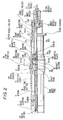
- Fig. 2 is a partly cross-sectional view illustrating a set of biopsy needles in the first embodiment according to the invention,
- Fig. 3 is a cross-sectional view along the line A-A in Fig. 2,
- Fig. 4 is a explanatory view illustrating tips of inner and outer needles in a set of biopsy needles in the first embodiment according to the invention,
- Fig. 5 is a partly cross-sectional view illustrating a set of biopsy needles in the second embodiment according to the invention,
- Fig. 6 is a partly cross-sectional view illustrating a shaft guide in a set of biopsy needles in the second embodiment according to the invention,
- Fig. 7 is a partly cross-sectional view illustrating a outer needle shaft in a set of biopsy needles in the second embodiment according to the invention,
- Fig. 8 is a partly cross-sectional view illustrating inner and outer needles in a set of biopsy needles in the second embodiment according to the invention,
- Fig. 9 is a explanatory view illustrating a set of biopsy needles in the third embodiment according to the invention, and
- Fig. 10 is a explanatory view illustrating a set of biopsy needles in the forth embodiment according to the invention.
- In Figs. 1 to 3, there is shown a set of biopsy needles in the first embodiment according to the invention. The set of biopsy needles is composed of an
inner needle holder 6 which has aninner needle base 22 at the front end to fix aninner needle 24, anouter needle holder 13 which is disposed outside theinner needle holder 6 and has anouter needle holder 21 at the front end to fix anouter needle 23, a main body tube 1 for gripping which is disposed outside theouter needle holder 13 to fix theinner needle holder 6 and to axially movably support theouter needle holder 13, aspring 9 which gives protrusion force to theouter needle holder 13 to protrude theouter needle 23 from the tip of theinner needle 24 as shown in Fig. 4, amagnet section 15 which holds theouter needle holder 13 at the position before protrusion against the protrusion force of thespring 9 and releases from holding by the rotation operation of aswitching lever 11B, and arotation shaft 10 which is fixed to the back end of theouter needle holder 13 with ascrew 19 and gives rotation force to theouter needle holder 13 when theouter needle holder 13 moves axially. - The main body tube 1 is composed of a front tube section 1A which is provided with a
slide stopper 2 and aback tube section 1B which is connected to back of the section 1A and, between these sections, there is provided a notch(an opening) 1C to control the range that theswitching lever 11B can rotate. The front tube section 1A contains an adjustingring 3 which is screwed at the tip thereof and can adjust the length of the protrusion of theouter needle 23, that is, the length of aclearance 3A according to the amount of screwing thereof, acap 4 which is attached at the tip of the adjustingring 3, and ascale 5 which is formed on the surface of the adjustingring 3 and indicates the length of the protrusion of theouter needle 23. On the other hand, theback tube section 1B contains a back stopper 7 which is fixed by thescrew 9 to the back end thereof, a metal fitting forfixing 20 which is connected inside the back stopper 7 and fixes thespring 9 and the rod of theinner needle holder 6 as described below, and ashaft guide 12 which is fixed inside the tip of theback tube section 1B, that is, inside the approximate center of the main body 1 by ascrew 17 and has apin 18 which protrudes to the center axis. - The
inner needle holder 6 has arod 6A which extends straightly to the back section of the main body tube 1 and is secured to the metal fitting for fixing 20 of the back stopper 7, whereby it is fixed to the main body tube 1. - The
outer needle holder 13 has astop section 13A in the form of a coaxial circular arc at the back end thereof which abuts on aprojection 11A of aswitching ring 11 as described below at the position before protrusion and is subjected to the rotation force of theswitching ring 11 and abuts on the back end of the adjustingring 3 when it protrudes according to the protrusion force of thespring 9, and it is provided with arubber ring 16 as a bumper at a portion of thestop section 13A where abuts on the back end of the adjustingring 3. - The switching
lever 11B is shaped into one body with theswitching ring 11 which is rotatably disposed inside the main body tube 1, and it is arranged so that it can rotate circumferentially. - The
magnet section 15 is composed of a circularmagnetic plate 15A which is fixed to the back end of theouter needle holder 13, that is, inside thestop section 13A via ayoke 14A and a circularmagnetic plate 15B which is fixed to theshaft guide 12 via ayoke 14B. Each of the circularmagnetic plates switching ring 11, theouter needle holder 13 is rotated, that is, the circularmagnetic plate 15A is rotated, whereby a relation of mutual pole provided with the two plates is varied to generate magnetic attractive or repulsive force between the two plates, so that theouter needle holder 13 is hold at the position before protrusion or is released from holding. That is, opposing N pole to S pole causes that theouter needle holder 13 can be held at the position before protrusion in accordance with the magnetic attractive force between the two plates, or opposing N pole to N pole or opposing S pole to S pole causes that theouter needle holder 13 can be released from holding at the position before protrusion in accordance with the magnetic repulsive force between the two plates. - As the circular
magnetic plates - The
rotation shaft 10 is provided with agroove 10A in spiral form on the outer surface into which thepin 19 of theshaft guide 12 as described above is engaged. That is, when it is protruded in accordance with the repulsive force of thespring 9, it is guided by thepin 19 to be rotated. - In operation, at first, the
switching lever 11B is positioned at the initial position when the N and S poles provided with the circularmagnetic plates outer needle holder 13 is held at the position before protrusion against the repulsive force of thespring 9 and the tip of theinner needle 24 is projected from theouter needle 23 as shown by a full line in Fig. 4. - Next, a doctor punctures a predetermined part in a human body by the double needles which the tip of
inner needle 24 is projected from theouter needle 23 while gripping the main body tube 1. - Thereafter, the
switching ring 11 is rotated by operating theswitching lever 11B to rotate theouter needle holder 13 via thestop portion 13A which abuts on theprojection 11A in theswitching ring 11, whereby the positions of the magnetic poles on the circularmagnetic plate 15A which is fixed to theouter needle holder 13 are changed. That is, the same magnetic poles on the circularmagnetic plates outer needle folder 13 is released when the repulsive force is generated, whereby theouter needle holder 13 is pushed forward in accordance with the repulsive force of thespring 9. On that time, a rotation force is given to theouter needle holder 13 since thepin 19 is engaged into thespiral groove 10A provided with therotation shaft 10. Accordingly, theouter needle 13 protrudes from the tip of the inner needle 14 as shown by the dotted line in Fig. 4 while being rotated. - When the
outer needle 23 protrudes in this manner, the affected tissue in the human body is cut off by the outer needle and is collected inside the tip of theouter needle 23, then the double needles are pulled back from the human body to collect a piece of tissue. Since theouter needle 23 is protruded while being rotated when a piece of tissue is cut off by theouter needle 23, cutting off the affected tissue can be done easily and surely. - In Fig. 5 to 8, there is shown a set of biopsy needles in the second embodiment. The set of biopsy needles is composed of an
outer needle shaft 34 which has a needlebase fixing portion 31 at the front end for fixing anouter needle base 54 as shown in Fig. 8 and has ashaft 42 at the back end, amain body tube 32 for gripping which supports axially movably theouter needle shaft 34, aspring outer needle shaft 34 to protrude anouter needle 55 from the tip of aninner needle 56, amagnet section 38 which holds theouter needle shaft 34 at the position before protrusion against the protrusion force of thespring 9 and releases from holding by the rotation operation of a switchinglever 36, and ashaft guide 33 which is disposed on the circumference of theouter needle shaft 34 inside themain body tube 32 and gives rotation force to theouter needle shaft 34 when theouter needle shaft 34 protrudes. - The
main body tube 32 is composed of afront tube section 32A which is provided with aslide stopper 30 and aback tube section 32B which is connected to back of thesection 32A. Aback stopper 51 has a fixingscrew 52 which fixes aninner needle base 57 in the shape of a rod which extends through theouter needle base 54 and to the back end of theback tube section 32 B when theouter needle base 54 which has theouter needle 55 at the front end thereof as shown in Fig. 8 is fixed to the needlebase fixing portion 31 which is located at the front end. - The
shaft guide 33 is shaped into a hollow tube as shown in Fig. 6 and is provided with aspiral groove 33A which passes from inside through outside of the tube. - The
outer needle shaft 34 is shaped into a tube which has a minor diameter portion and a major diameter portion as shown in Fig. 7 and is provided with ascrew groove 34B inside the front section thereof into which the needlebase fixing portion 31 is screwed and engaged and is provided with ascrew groove 34C inside the back section thereof into which theshaft 42 is screwed and engaged and has ascrew hole 34A into which theshaft pin 35 is fixed. - The switching
lever 36 is connected to theswitching ring 37A via aswitching pin 37 which is rotatably disposed inside themain body tube 32 and is arranged so that it can rotate circumferentially. Further, the switchingpin 37 abuts on theshaft pin 35, whereby theouter needle shaft 34 is rotated in accordance with the rotation of the switchinglever 37. - The
magnet section 38 is composed of a circularmagnetic plate 38A which is fixed to the circumference of theshaft 42 via ayoke 39 and a circularmagnetic plate 38B which is fixed via ayoke 40 to a fixing portion which is fixed to the inner surface of theback tube section 32B. As described in the first embodiment, each of the circularmagnetic plates lever 36, theshaft 42 is rotated, that is, the circularmagnetic plate 38A is rotated, whereby a relation of mutual pole on the two plates is varied to generate magnetic attractive or repulsive force between the two plates, so that theouter needle shaft 34 is held at the position before protrusion or is released from holding. - The
spring spring receiver 43 which is screwed and engaged into the back end of theshaft 42 and apipe base spring guide outer needle shaft 34 can be protruded when the repulsive force is generated at themagnet section 38 as described above. 50 is a thrust washer which is disposed between thepipe base 49 and theback stopper 51. - In the operation of the second embodiment, at first, the N and S poles provided with the circular
magnetic plates outer needle shaft 34 is held at the position before protrusion against the protrusion force of thespring 9 and the tip of theinner needle 56 is projected from theouter needle 55. - Next, a doctor punctures a predetermined part in a human body by the double needles which the tip of
inner needle 56 is projected from theouter needle 55 while gripping themain body tube 32. - Thereafter, the switching
lever 36 is rotated circumferentially to rotate theouter needle shaft 34 via theshaft pin 35 which abuts on the switchingpin 37, whereby the positions of the magnetic poles on the circularmagnetic plate 38A which is fixed on the circumference of theshaft 42 are changed. That is, the same magnetic poles on each of the circularmagnetic plate outer needle shaft 34 is released when the repulsive force is generated, whereby theshaft pin 35 on theouter needle shaft 34 is pushed forward in accordance with the repulsive force of thespring outer needle shaft 34 since theshaft pin 35 on theshaft 34 moves along thespiral groove 33A. Accordingly, theouter needle 55 is protruded from the tip of theinner needle 56 while being rotated. - Also in this embodiment, the
outer needle 55 is protruded while being rotated, so that cutting off the affected tissue can be done easily and surely to provide with enhanced reliability. - Furthermore, the shape of the
tip 55 A of theouter needle 55 as shown Fig. 9 and 10 can be suitably employed to enhance the performance to cut off tissue. - Although the invention has been described with respect to specific embodiment for complete and clear disclosure, the appended claims are not to be thus limited but are to be construed as embodying all modification and alternative constructions that may occur to one skilled in the art which fairly fall within the basic teaching herein set forth.
Claims (3)
- A set of biopsy needles comprising double needles composed of an outer needle in the form of a hollow tube and an inner needle to be inserted into said outer needle, which is punctured into an predetermined part in a human body and thereafter said outer needle is pushed forward to protrude from the tip of said inner needle whereby a piece of tissue in said part can be collected inside the tip of said outer needle, characterized in comprising:
a shaft member for said inner needle which has a needle base to fix said inner needle at the tip;
a shaft member for said outer needle which is located at the circumference of said shaft member for the inner needle and has a needle base to fix said outer needle at the tip;
a gripping member for operation which is located at the circumference of said shaft member for the outer needle and fixes said shaft member for the inner needle and supports axially movably said shaft member for the outer needle;
a actuating member which gives protrusion force to said shaft member for the outer member so that said outer needle can protrude from the tip of said inner needle;
a holding means which holds said shaft member for the outer needle at the position before protrusion against said protrusion force of said actuating member and releases said shaft member for the outer needle from said holding before protrusion by outside operation; and
a rotation generating means which gives rotation force to said shaft member for the outer needle to protrude said outer needle from the tip of said inner needle while being rotated when said shaft member for the outer needle moves axially by said protrusion force of said actuating member. - The set of biopsy needles according to claim 1, wherein said holding means comprises:
a first circular magnetic plate which is fixed to the circumference of said shaft member for the outer needle and can be rotated by said outside operation;
a second circular magnetic plate which is fixed at a predetermined position inside said main body tube; and
each of said first and second circular magnetic plate is circumferentially provided with a plurality of N and S poles which are located alternately. - The set of biopsy needles according to claim 1, wherein said rotation generating means comprises:
a guide pin which is attached inside said gripping member for operation; and
a spiral groove which is formed on the circumference of said shaft member for the outer needle and is engaged with said guide pin.
Applications Claiming Priority (3)
| Application Number | Priority Date | Filing Date | Title |
|---|---|---|---|
| JP12574294A JP3546074B2 (en) | 1994-05-16 | 1994-05-16 | Biopsy needle |
| JP125742/94 | 1994-05-16 | ||
| JP12574294 | 1994-05-16 |
Publications (2)
| Publication Number | Publication Date |
|---|---|
| EP0682915A1 true EP0682915A1 (en) | 1995-11-22 |
| EP0682915B1 EP0682915B1 (en) | 2001-01-10 |
Family
ID=14917675
Family Applications (1)
| Application Number | Title | Priority Date | Filing Date |
|---|---|---|---|
| EP94303759A Expired - Lifetime EP0682915B1 (en) | 1994-05-16 | 1994-05-25 | Biopsy needles |
Country Status (4)
| Country | Link |
|---|---|
| US (1) | US5505211A (en) |
| EP (1) | EP0682915B1 (en) |
| JP (1) | JP3546074B2 (en) |
| DE (1) | DE69426560T2 (en) |
Cited By (5)
| Publication number | Priority date | Publication date | Assignee | Title |
|---|---|---|---|---|
| WO1999044505A1 (en) * | 1998-03-06 | 1999-09-10 | Ascendia Ab | Impact-damped biopsy instrument |
| US6126617A (en) * | 1995-01-26 | 2000-10-03 | Ascendia Ab | Impact-damped biopsy instrument |
| AU736499B2 (en) * | 1998-03-06 | 2001-07-26 | Bifos Ab | Loading assembly for a biopsy instrument |
| EP1641398A1 (en) * | 2003-06-05 | 2006-04-05 | Eastland Medical Systems Ltd | Tissue-sampling needle |
| WO2009143534A1 (en) * | 2008-05-23 | 2009-11-26 | Pakter Robert L | Biopsy device with rotating needle |
Families Citing this family (28)
| Publication number | Priority date | Publication date | Assignee | Title |
|---|---|---|---|---|
| US5947989A (en) * | 1996-12-12 | 1999-09-07 | United States Surgical Corporation | Method and apparatus for transmyocardial revascularization |
| KR100213463B1 (en) * | 1997-03-31 | 1999-08-02 | 신명철 | Needle for sampling of tissue of living body and method for making of the same and operating device of the same |
| US6142955A (en) | 1997-09-19 | 2000-11-07 | United States Surgical Corporation | Biopsy apparatus and method |
| US6050955A (en) | 1997-09-19 | 2000-04-18 | United States Surgical Corporation | Biopsy apparatus and method |
| US6019733A (en) * | 1997-09-19 | 2000-02-01 | United States Surgical Corporation | Biopsy apparatus and method |
| US6193673B1 (en) | 1998-02-20 | 2001-02-27 | United States Surgical Corporation | Biopsy instrument driver apparatus |
| US6086543A (en) * | 1998-06-24 | 2000-07-11 | Rubicor Medical, Inc. | Fine needle and core biopsy devices and methods |
| CA2701452C (en) | 1998-11-25 | 2011-08-30 | United States Surgical Corporation | Biopsy system |
| US6165136A (en) * | 1998-12-23 | 2000-12-26 | Scimed Life Systems, Inc. | Semi-automatic biopsy device and related method of use |
| DK176336B1 (en) * | 1999-12-22 | 2007-08-20 | Asahi Optical Co Ltd | Endoscopic tissue collection instrument |
| US6358217B1 (en) | 2000-01-31 | 2002-03-19 | Hugh Bourassa | Automatic and semi-automatic disposable biopsy needle device |
| US6712773B1 (en) * | 2000-09-11 | 2004-03-30 | Tyco Healthcare Group Lp | Biopsy system |
| CA2429040C (en) * | 2000-11-27 | 2010-06-08 | Tyco Healthcare Group Lp | Tissue sampling and removal apparatus and method |
| JP4058614B2 (en) * | 2001-08-09 | 2008-03-12 | 株式会社Jimro | Bone marrow needle |
| DE10307722A1 (en) * | 2002-03-07 | 2003-11-13 | Enomoto Co Ltd | Medical device |
| ATE551973T1 (en) * | 2003-06-10 | 2012-04-15 | Neomedix Corp | TUBULAR CUTTING DEVICE |
| US7988642B2 (en) * | 2003-10-14 | 2011-08-02 | Suros Surgical Systems, Inc. | Vacuum assisted biopsy device |
| US8048003B2 (en) * | 2003-10-14 | 2011-11-01 | Suros Surgical Systems, Inc. | Vacuum assisted biopsy device |
| US8357103B2 (en) | 2003-10-14 | 2013-01-22 | Suros Surgical Systems, Inc. | Vacuum assisted biopsy needle set |
| JP4500315B2 (en) * | 2003-10-14 | 2010-07-14 | シュロス・サージカル・システムズ・インコーポレーテッド | Vacuum assisted biopsy needle set |
| EP1830713B1 (en) * | 2004-11-29 | 2011-03-16 | Granit Medical Innovations, LLC | Rotating fine needle for core tissue sampling |
| US20120010527A1 (en) * | 2010-02-25 | 2012-01-12 | Promex Technologies, Llc | Full core biopsy device |
| US9968337B2 (en) * | 2010-12-20 | 2018-05-15 | Cook Medical Technologies Llc | Coring tissue biopsy needle and method of use |
| US8905944B2 (en) | 2011-09-07 | 2014-12-09 | Vlv Associates, Inc. | Protective cover assembly for a needle assembly |
| WO2013082259A1 (en) * | 2011-11-29 | 2013-06-06 | Promex Technologies, Llc | Full core biopsy device |
| CN104797200B (en) | 2012-11-21 | 2018-04-27 | C·R·巴德公司 | Core needle biopsy device |
| WO2016081278A1 (en) * | 2014-11-18 | 2016-05-26 | Alec Goldenberg | Biopsy needle |
| EP3606441B1 (en) | 2017-04-06 | 2022-04-27 | Alec Goldenberg | Biopsy needle |
Citations (4)
| Publication number | Priority date | Publication date | Assignee | Title |
|---|---|---|---|---|
| DE1117258B (en) * | 1959-10-19 | 1961-11-16 | Medizintechnik Leipzig Veb | Sample excision device |
| US3929123A (en) * | 1973-02-07 | 1975-12-30 | Khosrow Jamshidi | Muscle biopsy needle |
| DE2435123A1 (en) * | 1974-07-22 | 1976-02-05 | Magnaperm | Controllable permanent magnetic power generator - has compensating magnets to reduce magnetic interactions in setting direction |
| EP0390528A1 (en) * | 1989-03-29 | 1990-10-03 | Gregory W. Baran | Automated biopsy instrument |
Family Cites Families (10)
| Publication number | Priority date | Publication date | Assignee | Title |
|---|---|---|---|---|
| US3995619A (en) * | 1975-10-14 | 1976-12-07 | Glatzer Stephen G | Combination subcutaneous suture remover, biopsy sampler and syringe |
| US4517965A (en) * | 1983-06-27 | 1985-05-21 | Ellison Arthur E | Tissue retractor |
| US4671292A (en) * | 1985-04-30 | 1987-06-09 | Dymax Corporation | Concentric biopsy probe |
| US4907599A (en) * | 1988-02-01 | 1990-03-13 | Hart Enterprises, Inc. | Soft tissue core biopsy instrument |
| US4958625A (en) * | 1989-07-18 | 1990-09-25 | Boston Scientific Corporation | Biopsy needle instrument |
| DE4006175A1 (en) * | 1990-02-28 | 1991-08-29 | Angiomed Ag | Taking corporeal samples by biopsy - by hollow needle in which stiletto is inserted, both needle and stiletto being spring-activated |
| US5188118A (en) * | 1990-11-07 | 1993-02-23 | Terwilliger Richard A | Automatic biopsy instrument with independently actuated stylet and cannula |
| US5226426A (en) * | 1990-12-18 | 1993-07-13 | Inbae Yoon | Safety penetrating instrument |
| US5127419A (en) * | 1991-07-02 | 1992-07-07 | Antoine Kaldany | Biopsy instrument with slotted driving member |
| IT1252234B (en) * | 1991-12-18 | 1995-06-05 | Bauer Di Bauer Albeto | DEVICE FOR THE SAFE PERFORMANCE OF A BIOPSY, IN PARTICULAR OSTEO-BONE MARROW |
-
1994
- 1994-05-16 JP JP12574294A patent/JP3546074B2/en not_active Expired - Fee Related
- 1994-05-25 EP EP94303759A patent/EP0682915B1/en not_active Expired - Lifetime
- 1994-05-25 DE DE69426560T patent/DE69426560T2/en not_active Expired - Fee Related
- 1994-05-27 US US08/250,800 patent/US5505211A/en not_active Expired - Fee Related
Patent Citations (4)
| Publication number | Priority date | Publication date | Assignee | Title |
|---|---|---|---|---|
| DE1117258B (en) * | 1959-10-19 | 1961-11-16 | Medizintechnik Leipzig Veb | Sample excision device |
| US3929123A (en) * | 1973-02-07 | 1975-12-30 | Khosrow Jamshidi | Muscle biopsy needle |
| DE2435123A1 (en) * | 1974-07-22 | 1976-02-05 | Magnaperm | Controllable permanent magnetic power generator - has compensating magnets to reduce magnetic interactions in setting direction |
| EP0390528A1 (en) * | 1989-03-29 | 1990-10-03 | Gregory W. Baran | Automated biopsy instrument |
Cited By (7)
| Publication number | Priority date | Publication date | Assignee | Title |
|---|---|---|---|---|
| US6126617A (en) * | 1995-01-26 | 2000-10-03 | Ascendia Ab | Impact-damped biopsy instrument |
| WO1999044505A1 (en) * | 1998-03-06 | 1999-09-10 | Ascendia Ab | Impact-damped biopsy instrument |
| AU731310B2 (en) * | 1998-03-06 | 2001-03-29 | Bifos Ab | Impact-damped biopsy instrument |
| AU736499B2 (en) * | 1998-03-06 | 2001-07-26 | Bifos Ab | Loading assembly for a biopsy instrument |
| EP1641398A1 (en) * | 2003-06-05 | 2006-04-05 | Eastland Medical Systems Ltd | Tissue-sampling needle |
| EP1641398A4 (en) * | 2003-06-05 | 2009-05-20 | Eastland Medical Systems Ltd | Tissue-sampling needle |
| WO2009143534A1 (en) * | 2008-05-23 | 2009-11-26 | Pakter Robert L | Biopsy device with rotating needle |
Also Published As
| Publication number | Publication date |
|---|---|
| JP3546074B2 (en) | 2004-07-21 |
| EP0682915B1 (en) | 2001-01-10 |
| DE69426560T2 (en) | 2001-05-31 |
| JPH07308320A (en) | 1995-11-28 |
| DE69426560D1 (en) | 2001-02-15 |
| US5505211A (en) | 1996-04-09 |
Similar Documents
| Publication | Publication Date | Title |
|---|---|---|
| EP0682915B1 (en) | Biopsy needles | |
| RU2160053C2 (en) | Instrument for biopsy and disposable set of instruments for biopsy | |
| EP1405595B1 (en) | Piercing device | |
| US20220361785A1 (en) | Magnetic lancet device | |
| CA2037056A1 (en) | Tissue sampler | |
| US6165136A (en) | Semi-automatic biopsy device and related method of use | |
| US5025797A (en) | Automated biopsy instrument | |
| US11083362B2 (en) | Medical device for moving a medical instrument | |
| AU681926B2 (en) | Suture probe | |
| US20100312266A1 (en) | Puncture device | |
| ATE317563T1 (en) | WINDING DEVICE FOR MECHANICAL WATCHES | |
| US5856806A (en) | Antenna support sleeve with fingerlock | |
| US6312434B1 (en) | Device for producing a shock wave to impact an object | |
| CN2938374Y (en) | Movable contact drive structure of vacuum circuit breaker | |
| US20040231428A1 (en) | Device for making secure a mobile member displacement | |
| CN112616787B (en) | Fishing reel with fixed constant-acting brake and movable inertia brake | |
| JP2008183020A (en) | Biopsy needle | |
| CN219250278U (en) | Traction device for gastrointestinal mucosa | |
| US20220329929A1 (en) | Earpiece | |
| JPS6232513Y2 (en) | ||
| CA2072974A1 (en) | Biopsy instrument, stylet and cannula assembly | |
| EP0730287A3 (en) | Trip device for a circuit breaker | |
| KR19980063797U (en) | Centering device of plug luer | |
| KR900015694A (en) | Buttock prosthetic cups fixed without binder |
Legal Events
| Date | Code | Title | Description |
|---|---|---|---|
| PUAI | Public reference made under article 153(3) epc to a published international application that has entered the european phase |
Free format text: ORIGINAL CODE: 0009012 |
|
| AK | Designated contracting states |
Kind code of ref document: A1 Designated state(s): DE FR GB IT |
|
| 17P | Request for examination filed |
Effective date: 19960503 |
|
| 17Q | First examination report despatched |
Effective date: 19990802 |
|
| GRAG | Despatch of communication of intention to grant |
Free format text: ORIGINAL CODE: EPIDOS AGRA |
|
| RAP1 | Party data changed (applicant data changed or rights of an application transferred) |
Owner name: HAKKO MEDICAL CO., LTD. |
|
| GRAG | Despatch of communication of intention to grant |
Free format text: ORIGINAL CODE: EPIDOS AGRA |
|
| GRAH | Despatch of communication of intention to grant a patent |
Free format text: ORIGINAL CODE: EPIDOS IGRA |
|
| GRAH | Despatch of communication of intention to grant a patent |
Free format text: ORIGINAL CODE: EPIDOS IGRA |
|
| GRAA | (expected) grant |
Free format text: ORIGINAL CODE: 0009210 |
|
| AK | Designated contracting states |
Kind code of ref document: B1 Designated state(s): DE FR GB IT |
|
| ITF | It: translation for a ep patent filed |
Owner name: BUZZI, NOTARO&ANTONIELLI D'OULX |
|
| REF | Corresponds to: |
Ref document number: 69426560 Country of ref document: DE Date of ref document: 20010215 |
|
| ET | Fr: translation filed | ||
| PLBE | No opposition filed within time limit |
Free format text: ORIGINAL CODE: 0009261 |
|
| STAA | Information on the status of an ep patent application or granted ep patent |
Free format text: STATUS: NO OPPOSITION FILED WITHIN TIME LIMIT |
|
| REG | Reference to a national code |
Ref country code: GB Ref legal event code: IF02 |
|
| 26N | No opposition filed | ||
| PGFP | Annual fee paid to national office [announced via postgrant information from national office to epo] |
Ref country code: FR Payment date: 20040510 Year of fee payment: 11 |
|
| PGFP | Annual fee paid to national office [announced via postgrant information from national office to epo] |
Ref country code: GB Payment date: 20040519 Year of fee payment: 11 |
|
| PGFP | Annual fee paid to national office [announced via postgrant information from national office to epo] |
Ref country code: DE Payment date: 20040603 Year of fee payment: 11 |
|
| PG25 | Lapsed in a contracting state [announced via postgrant information from national office to epo] |
Ref country code: IT Free format text: LAPSE BECAUSE OF NON-PAYMENT OF DUE FEES Effective date: 20050525 Ref country code: GB Free format text: LAPSE BECAUSE OF NON-PAYMENT OF DUE FEES Effective date: 20050525 |
|
| PG25 | Lapsed in a contracting state [announced via postgrant information from national office to epo] |
Ref country code: DE Free format text: LAPSE BECAUSE OF NON-PAYMENT OF DUE FEES Effective date: 20051201 |
|
| GBPC | Gb: european patent ceased through non-payment of renewal fee |
Effective date: 20050525 |
|
| PG25 | Lapsed in a contracting state [announced via postgrant information from national office to epo] |
Ref country code: FR Free format text: LAPSE BECAUSE OF NON-PAYMENT OF DUE FEES Effective date: 20060131 |
|
| REG | Reference to a national code |
Ref country code: FR Ref legal event code: ST Effective date: 20060131 |