EP0677695A2 - Lighting device, in particular emergency lighting device for the interior of watercrafts - Google Patents
Lighting device, in particular emergency lighting device for the interior of watercrafts Download PDFInfo
- Publication number
- EP0677695A2 EP0677695A2 EP95105069A EP95105069A EP0677695A2 EP 0677695 A2 EP0677695 A2 EP 0677695A2 EP 95105069 A EP95105069 A EP 95105069A EP 95105069 A EP95105069 A EP 95105069A EP 0677695 A2 EP0677695 A2 EP 0677695A2
- Authority
- EP
- European Patent Office
- Prior art keywords
- lighting device
- carrier
- luminous elements
- housing
- luminous
- Prior art date
- Legal status (The legal status is an assumption and is not a legal conclusion. Google has not performed a legal analysis and makes no representation as to the accuracy of the status listed.)
- Withdrawn
Links
Images

Classifications
-
- H—ELECTRICITY
- H05—ELECTRIC TECHNIQUES NOT OTHERWISE PROVIDED FOR
- H05K—PRINTED CIRCUITS; CASINGS OR CONSTRUCTIONAL DETAILS OF ELECTRIC APPARATUS; MANUFACTURE OF ASSEMBLAGES OF ELECTRICAL COMPONENTS
- H05K1/00—Printed circuits
- H05K1/18—Printed circuits structurally associated with non-printed electric components
- H05K1/189—Printed circuits structurally associated with non-printed electric components characterised by the use of a flexible or folded printed circuit
-
- F—MECHANICAL ENGINEERING; LIGHTING; HEATING; WEAPONS; BLASTING
- F21—LIGHTING
- F21S—NON-PORTABLE LIGHTING DEVICES; SYSTEMS THEREOF; VEHICLE LIGHTING DEVICES SPECIALLY ADAPTED FOR VEHICLE EXTERIORS
- F21S4/00—Lighting devices or systems using a string or strip of light sources
- F21S4/20—Lighting devices or systems using a string or strip of light sources with light sources held by or within elongate supports
- F21S4/22—Lighting devices or systems using a string or strip of light sources with light sources held by or within elongate supports flexible or deformable, e.g. into a curved shape
- F21S4/24—Lighting devices or systems using a string or strip of light sources with light sources held by or within elongate supports flexible or deformable, e.g. into a curved shape of ribbon or tape form, e.g. LED tapes
-
- F—MECHANICAL ENGINEERING; LIGHTING; HEATING; WEAPONS; BLASTING
- F21—LIGHTING
- F21S—NON-PORTABLE LIGHTING DEVICES; SYSTEMS THEREOF; VEHICLE LIGHTING DEVICES SPECIALLY ADAPTED FOR VEHICLE EXTERIORS
- F21S43/00—Signalling devices specially adapted for vehicle exteriors, e.g. brake lamps, direction indicator lights or reversing lights
- F21S43/10—Signalling devices specially adapted for vehicle exteriors, e.g. brake lamps, direction indicator lights or reversing lights characterised by the light source
- F21S43/13—Signalling devices specially adapted for vehicle exteriors, e.g. brake lamps, direction indicator lights or reversing lights characterised by the light source characterised by the type of light source
- F21S43/14—Light emitting diodes [LED]
-
- F—MECHANICAL ENGINEERING; LIGHTING; HEATING; WEAPONS; BLASTING
- F21—LIGHTING
- F21S—NON-PORTABLE LIGHTING DEVICES; SYSTEMS THEREOF; VEHICLE LIGHTING DEVICES SPECIALLY ADAPTED FOR VEHICLE EXTERIORS
- F21S43/00—Signalling devices specially adapted for vehicle exteriors, e.g. brake lamps, direction indicator lights or reversing lights
- F21S43/10—Signalling devices specially adapted for vehicle exteriors, e.g. brake lamps, direction indicator lights or reversing lights characterised by the light source
- F21S43/13—Signalling devices specially adapted for vehicle exteriors, e.g. brake lamps, direction indicator lights or reversing lights characterised by the light source characterised by the type of light source
- F21S43/15—Strips of light sources
-
- F—MECHANICAL ENGINEERING; LIGHTING; HEATING; WEAPONS; BLASTING
- F21—LIGHTING
- F21S—NON-PORTABLE LIGHTING DEVICES; SYSTEMS THEREOF; VEHICLE LIGHTING DEVICES SPECIALLY ADAPTED FOR VEHICLE EXTERIORS
- F21S8/00—Lighting devices intended for fixed installation
- F21S8/03—Lighting devices intended for fixed installation of surface-mounted type
- F21S8/032—Lighting devices intended for fixed installation of surface-mounted type the surface being a floor or like ground surface, e.g. pavement
-
- F—MECHANICAL ENGINEERING; LIGHTING; HEATING; WEAPONS; BLASTING
- F21—LIGHTING
- F21V—FUNCTIONAL FEATURES OR DETAILS OF LIGHTING DEVICES OR SYSTEMS THEREOF; STRUCTURAL COMBINATIONS OF LIGHTING DEVICES WITH OTHER ARTICLES, NOT OTHERWISE PROVIDED FOR
- F21V31/00—Gas-tight or water-tight arrangements
-
- F—MECHANICAL ENGINEERING; LIGHTING; HEATING; WEAPONS; BLASTING
- F21—LIGHTING
- F21W—INDEXING SCHEME ASSOCIATED WITH SUBCLASSES F21K, F21L, F21S and F21V, RELATING TO USES OR APPLICATIONS OF LIGHTING DEVICES OR SYSTEMS
- F21W2107/00—Use or application of lighting devices on or in particular types of vehicles
- F21W2107/20—Use or application of lighting devices on or in particular types of vehicles for water vehicles
-
- F—MECHANICAL ENGINEERING; LIGHTING; HEATING; WEAPONS; BLASTING
- F21—LIGHTING
- F21Y—INDEXING SCHEME ASSOCIATED WITH SUBCLASSES F21K, F21L, F21S and F21V, RELATING TO THE FORM OR THE KIND OF THE LIGHT SOURCES OR OF THE COLOUR OF THE LIGHT EMITTED
- F21Y2115/00—Light-generating elements of semiconductor light sources
- F21Y2115/10—Light-emitting diodes [LED]
-
- H—ELECTRICITY
- H05—ELECTRIC TECHNIQUES NOT OTHERWISE PROVIDED FOR
- H05K—PRINTED CIRCUITS; CASINGS OR CONSTRUCTIONAL DETAILS OF ELECTRIC APPARATUS; MANUFACTURE OF ASSEMBLAGES OF ELECTRICAL COMPONENTS
- H05K1/00—Printed circuits
- H05K1/02—Details
- H05K1/0286—Programmable, customizable or modifiable circuits
- H05K1/029—Programmable, customizable or modifiable circuits having a programmable lay-out, i.e. adapted for choosing between a few possibilities
-
- H—ELECTRICITY
- H05—ELECTRIC TECHNIQUES NOT OTHERWISE PROVIDED FOR
- H05K—PRINTED CIRCUITS; CASINGS OR CONSTRUCTIONAL DETAILS OF ELECTRIC APPARATUS; MANUFACTURE OF ASSEMBLAGES OF ELECTRICAL COMPONENTS
- H05K2201/00—Indexing scheme relating to printed circuits covered by H05K1/00
- H05K2201/10—Details of components or other objects attached to or integrated in a printed circuit board
- H05K2201/10007—Types of components
- H05K2201/10106—Light emitting diode [LED]
-
- H—ELECTRICITY
- H05—ELECTRIC TECHNIQUES NOT OTHERWISE PROVIDED FOR
- H05K—PRINTED CIRCUITS; CASINGS OR CONSTRUCTIONAL DETAILS OF ELECTRIC APPARATUS; MANUFACTURE OF ASSEMBLAGES OF ELECTRICAL COMPONENTS
- H05K2203/00—Indexing scheme relating to apparatus or processes for manufacturing printed circuits covered by H05K3/00
- H05K2203/17—Post-manufacturing processes
- H05K2203/175—Configurations of connections suitable for easy deletion, e.g. modifiable circuits or temporary conductors for electroplating; Processes for deleting connections
Definitions
- the invention relates to a lighting device, in particular emergency lighting device for the interior of watercraft according to the preamble of claims 1, 7, 10 and 13.
- Lighting devices in particular emergency lighting devices for the interior of watercraft, are intended in the event of an accident, e.g. of a fire on board, showing the passengers the saving way to the exit. They are installed close to the floor and must be moisture-proof to ensure functionality.
- Such lighting devices consist of a lighting unit and, if appropriate, a housing accommodating them.
- the lighting unit comprises a carrier, luminous element, Series resistors and possibly further electrical or electronic components.
- the lighting unit of previously known emergency lighting devices consists of rigid modules. These are inserted into each other when laying.
- the rigid modules cannot be made moisture-proof due to the required electrical plug connections and must therefore be installed in a sealed housing.
- the installation of these emergency lighting devices is associated with great effort.
- the electrical plug connections are prone to errors.
- the system reliability of known emergency lighting devices is limited.
- due to the rigidity curved structures cannot be equipped with known emergency lighting devices or can only be equipped with great effort.
- the object of the invention is to create lighting devices that are reliable and that can be installed and manufactured with little effort.
- the lighting device according to the invention has the features of claim 1. This has the advantage that the lighting unit is designed to be bendable. Curved structures can be easily equipped with this. It can also be laid endlessly. The lighting unit can also be inserted into existing housings by simply pushing them in.
- At least the luminous element and the conductor are preferably arranged moisture-tight on the carrier web. This has the advantage that the lighting unit itself is already moisture-proof is. The housing in which the lighting unit is installed does not have to be moisture-proof.
- the lighting device has the features of claim 9.
- the lighting device can be installed in a simple manner and with little effort without fault-prone plug connections.
- the lighting device has the features of claim 13.
- the or each pictogram is arranged in the same housing as the luminous element and / or conductor. This configuration also ensures that the lighting device can be installed with little effort and no separate housing is required for the or each pictogram.
- the lighting device has the features of claim 16.
- the use of luminous elements with a large radiation angle means that the combination of several diodes at one point in the lighting device or lighting unit, which is complex in terms of production technology, can be dispensed with.
- the light emitted by each individual illuminant is clearly recognizable from practically all directions, and the result is excellent visibility. This property is particularly important at small viewing angles with respect to a horizontal line, since the people fleeing are usually near the ground when there is a lot of smoke.
- the lighting device shown in the drawing serves as an emergency lighting device for the interior of watercraft. This is installed near the floor or on the floor.
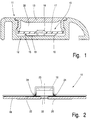
- the lighting device shown in FIG. 1 consists of a lighting unit 10 arranged in a housing 11.
- the housing 11 consists of a profile 12 and a cover 13.
- the profile 12 is preferably made of aluminum, the cover 13 of transparent material.
- a base piece 14 of the profile 12 has two strips 15, 16 arranged at a distance from one another and extending in the longitudinal direction of the profile 12, between which the lighting unit 10 is fixed in a desired position.
- a cover sheet 17 is supported on the strips 15, 16 and partially covers the lighting unit 10, namely outside the area of the luminous elements 18.
- the cover sheet 17 supports together with the latched cover 13, the fixation of the lighting unit 10 inserted into the profile 12. Further attachment by means of, for example, adhesive strips is not necessary.
- the cover film 17 can be colored as desired and decoratively covers the lighting unit 10.
- the lighting unit 10 consists of a carrier 19 and electrical conductors attached to it, namely two continuous supply conductors 20, 21 and a central conductor 22.
- the carrier 19 is designed as a continuous, flexible, flexible carrier track, e.g. from a polyimide film.
- the film of the carrier web has a thickness of approx. 50 ⁇ m.
- Luminous elements 18 are applied to the unit consisting of carrier 19, supply conductors 20, 21 and center conductor 22.
- the luminous bodies 18 are designed as luminescent diodes (LEDs).
- series resistors 23 are applied to the carrier. Luminous body 18 and series resistors 23 are applied mechanically to the carrier using SMD technology and soldered to a monolithic block (solder joints 24).
- This monolithic block is covered on all sides by a moisture-proof protective coating 25.
- the protective cover 25 is highly transparent and flexible.
- a silicone protective lacquer or also a protective coating with poly-para-xylylene is preferably used as the protective coating 25.
- the protective coating 25 is evaporated onto the monolithic block composed of carrier 19, conductors 20, 22 and series resistors 23.
- the protective coating 25 has a thickness of 25 microns to 40 microns. Alternatively, it is possible that the protective coating 25 is only partially applied to the monolithic block, namely in the area of the electrical or electronic assemblies.
- the lighting unit 10 is accordingly moisture-proof. When the lighting unit 10 is installed in the housing 11, it does not have to be sealed at the connection points between the profile 12 and the cover 13.
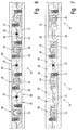
- the layout shown in FIG. 3 for the supply conductors 20, 21 and central conductors 22 consists of cyclically repeating and seamlessly merging structures 26.
- a central area 27 of the structure 26 is used to attach the luminous elements 18 and series resistors 23, the overlap regions 28, 29 serve to overlap individual structures 26.
- the overlapping arrangement of the structures 26 shown in FIGS. 6 and 7 results in continuous supply conductor tracks 20, 21 and center conductors 22.
- the always identical layout of the conductors 20. 22 of a structure 26 applied to the carrier 19 can be equipped with luminous elements 18 or series resistors 23 in different ways, depending on the desired wiring of the entire lighting unit 10.
- the central conductor 22 in the central region 27 has regions 30 for the arrangement of the series resistors 23 and a region 31 for the arrangement of the luminous element 18.
- FIG. 4 shows a structure 26 equipped with two series resistors 23 and a lighting element 18
- an illuminating device 10 is created in which the illuminating bodies 18 are all arranged in parallel (FIG. 6).
- the central conductor 22 must be interrupted in the overlap regions 28, 29.
- the central conductor 22 is provided with punchings 32 in the overlap regions 28, 29.
- the center conductor 22 is also provided with a punched-out 33 for circuitry reasons.
- FIG. 5 shows a further possible configuration of the structure 26.
- the structure 26 is only equipped with a series resistor in one area 30.
- the other area 30 of the central conductor remains free.
- a luminous element 18 is applied to the structure 26 in the area 31.
- FIG. 7 shows a lighting unit 10 composed of groups of luminous elements 34 connected in parallel, each group of luminous elements 34 consisting of two series of luminous elements 18.
- Each filament group 34 is delimited by two series resistors 23. Between the filaments 18 of a filament group 34 no further resistors are provided.
- punched-out areas 33 are provided only in the area of the lamp bodies 18 arranged on the central conductor 22. Punchings 32 of the central conductor 22 in the overlap regions 28, 29 are provided only for the separation and thus parallel connection of the individual lamp body groups 34.
- the luminous elements are designed as luminescent diodes (LEDs). LEDs with a radiation angle of preferably 120 ° are provided. Even with a small number of light-emitting diodes, this ensures excellent visibility of the light emitted by the LEDs from practically all directions. The good visibility of the light emitted by the LEDs is enhanced by the cover 13.
- the cover 13 made of a translucent, preferably crystal-clear material has a refractive index greater than 1, preferably 1.55. As a result, the virtual radiation source is clearly shifted upwards for the observer.
- the cover 13, like the lighting unit 10 and the cover film 17, is made of elastic, flexible material. This ensures a particularly simple installation of the lighting device without seams.
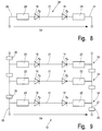
- FIG. 8 shows an equivalent circuit diagram for a lamp body group 34 which, according to the exemplary embodiment according to FIG. 7, consists of two lamp bodies 18 connected in series. A plurality of luminous element groups 34 connected in parallel form the lighting unit 10.
- the possible number of lamps 18 per lamp group 34 depends on the selected operating voltage US, the selected operating point of the LEDs and the desired efficiency of the lighting device or lighting unit. If several lighting element groups 34 are connected in parallel to a lighting unit 10, the rail resistor 35 of the supply conductor must be used 20, 21 are taken into account. The Bahr resistors 35 cause energy losses and cause a decrease in the luminous intensity of the luminous bodies 18. Nevertheless, it has been shown that almost endless lighting devices can be created according to the construction principle discussed above.
- Supply conductors 20, 21 and center conductors 22 are continuous in the non-assembled state, i.e. trained without interruption. This allows the conductors 20..22 to be galvanized and provided with a continuous nickel or gold layer.
- Pictograms are assigned to the lighting device. According to the invention, the pictograms are arranged in the same housing 11 as the lighting unit 10. Because of the flat design of the lighting unit 10, it is possible to arrange the pictogram in the space 36 between the cover film 17 or lighting unit 10 and cover 13 of the housing 11. When installed, the pictogram covers the lighting unit 10.
- the lighting device is installed on or near the floor.
- the housing 11 for receiving the lighting unit 10 can be designed on the one hand as a baseboard, on the other hand the housing 11 can be integrated into the floor area.
- the housing 11 is designed to be unbreakable.
- the cover 13 of the housing 11 is also scratch-resistant.
- the lighting unit 10 can also be installed without a housing 11.
- the terms lighting unit and lighting device are synonymous.
Abstract
Description
Die Erfindung betrifft eine Beleuchtungseinrichtung, insbesondere Notbeleuchtungseinrichtung für das Innere von Wasserfahrzeugen nach dem Oberbegriff der Ansprüche 1, 7, 10 und 13.The invention relates to a lighting device, in particular emergency lighting device for the interior of watercraft according to the preamble of
Beleuchtungseinrichtungen, insbesondere Notbeleuchtungseinrichtungen für das Innere von Wasserfahrzeugen, sollen im Falle einer Havarie, z.B. eines Feuers an Bord, den Passagieren den rettenden Weg zum Ausgang weisen. Sie werden in Bodennähe verlegt und müssen zur Wahrung der Funktionalität feuchtigkeitsdicht ausgebildet sein.Lighting devices, in particular emergency lighting devices for the interior of watercraft, are intended in the event of an accident, e.g. of a fire on board, showing the passengers the saving way to the exit. They are installed close to the floor and must be moisture-proof to ensure functionality.
Derartige Beleuchtungseinrichtungen bestehen aus einer Beleuchtungseinheit und gegebenenfalls einem diese aufnehmenden Gehäuse. Die Beleuchtungseinheit umfaßt einen Träger, Leuchtkörper, Vorwiderstände und gegebenenfalls weitere elektrische bzw. elektronische Bauelemente.Such lighting devices consist of a lighting unit and, if appropriate, a housing accommodating them. The lighting unit comprises a carrier, luminous element, Series resistors and possibly further electrical or electronic components.
Die Beleuchtungseinheit bisher bekannter Notbeleuchtungseinrichtungen besteht aus starren Modulen. Diese werden beim Verlegen ineinander gesteckt. Die starren Module lassen sich aufgrund der erforderlichen elektrischen Steckverbindungen nicht feuchtigkeitsdicht ausbilden und müssen demzufolge in einem dichten Gehäuse verlegt werden. Das Verlegen dieser Notbeleuchtungseinrichtungen ist mit hohem Aufwand verbunden. Desweiteren sind die elektrischen Steckverbindungen fehleranfällig. Die Systemzuverlässigkeit bekannter Notbeleuchtungseinrichtungen ist begrenzt. Ferner können aufgrund der Starrheit mit bekannten Notbeleuchtungseinrichtungen gekrümmte Strukturen nicht oder nur mit großem Aufwand ausgestattet werden.The lighting unit of previously known emergency lighting devices consists of rigid modules. These are inserted into each other when laying. The rigid modules cannot be made moisture-proof due to the required electrical plug connections and must therefore be installed in a sealed housing. The installation of these emergency lighting devices is associated with great effort. Furthermore, the electrical plug connections are prone to errors. The system reliability of known emergency lighting devices is limited. Furthermore, due to the rigidity, curved structures cannot be equipped with known emergency lighting devices or can only be equipped with great effort.
Desweiteren weisen bekannte Notbeleuchtungseinrichtungen für das Innere von Wasserfahrzeugen den Nachteil auf, daß zur funktionsgerechten Ausleuchtung z.B. eines Fluchtweges an einer Stelle mehrere Leuchtkörper miteinander kombiniert werden müssen, die unterschiedlich zur Modulnormalen ausgerichtet sind. Dies ist fertigungstechnisch besonders aufwendig.Furthermore, known emergency lighting devices for the interior of watercraft have the disadvantage that, for functional lighting, e.g. of an escape route, several light fixtures have to be combined at one point, which are aligned differently to the module normal. This is particularly complex in terms of production technology.
Ausgehend von den bekannten Beleuchtungseinrichtungen liegt der Erfindung die Aufgabe zugrunde, eine Beleuchtungseinrichtungen zu schaffen, die zuverlässig ist und mit geringem Aufwand verlegt sowie gefertigt werden kann.Starting from the known lighting devices, the object of the invention is to create lighting devices that are reliable and that can be installed and manufactured with little effort.
Zur Lösung dieser Aufgabe weist die erfindungsgemäße Beleuchtungseinrichtung die Merkmale des Anspruchs 1 auf. Dies hat den Vorteil, daß die Beleuchtungseinheit biegefähig ausgebildet ist. Gekrümmte Strukturen können mit dieser auf einfache Weise ausgestattet werden. Sie läßt sich zudem endlos verlegen. Die Beleuchtungseinheit kann außerdem durch einfaches Einschieben in bereits vorhandene Gehäuse eingebracht werden.To achieve this object, the lighting device according to the invention has the features of claim 1. This has the advantage that the lighting unit is designed to be bendable. Curved structures can be easily equipped with this. It can also be laid endlessly. The lighting unit can also be inserted into existing housings by simply pushing them in.
Vorzugsweise sind mindestens Leuchtkörper und Leiter feuchtigkeitsdicht auf der Trägerbahn angeordnet. Dies hat den Vorteil, daß die Beleuchtungseinheit an sich bereits feuchtigkeitsdicht ist. Das Gehäuse, in dem die Beleuchtungseinheit verlegt wird, muß nicht feuchtigkeitsdicht ausgebildet sein.At least the luminous element and the conductor are preferably arranged moisture-tight on the carrier web. This has the advantage that the lighting unit itself is already moisture-proof is. The housing in which the lighting unit is installed does not have to be moisture-proof.
Nach einer vorteilhaften Ausgestaltung der erfindungsgemäßen Beleuchtungseinrichtung weist diese die Merkmale des Anspruchs 9 auf. Die Beleuchtungseinrichtung kann ohne fehleranfällige Steckverbindungen auf einfache Weise und mit geringem Aufwand verlegt werden.According to an advantageous embodiment of the lighting device according to the invention, it has the features of claim 9. The lighting device can be installed in a simple manner and with little effort without fault-prone plug connections.
Nach einer weiteren vorteilhaften Ausgestaltung der Erfindung weist die Beleuchtungseinrichtung die Merkmale des Anspruchs 13 auf. Das oder jedes Piktogramm ist in demselben Gehäuse wie Leuchtkörper und/oder Leiter angeordnet. Diese Ausgestaltung sorgt ebenfalls dafür, daß die Beleuchtungseinrichtung mit geringem Aufwand verlegt werden kann und kein separates Gehäuse für das oder jedes Piktogramm erforderlich ist.According to a further advantageous embodiment of the invention, the lighting device has the features of
Nach einer weiteren vorteilhaften Ausgestaltung der Erfindung weist die Beleuchtungseinrichtung die Merkmale des Anspruchs 16 auf. Durch Verwendung von Leuchtkörpern mit einem großen Abstrahlwinkel kann auf die fertigungstechnisch aufwendige Kombination mehrerer Dioden an einer Stelle der Beleuchtungseinrichtung bzw. Beleuchtungseinheit verzichtet werden. Das von jedem einzelnen Leuchtkörper emitierte Licht ist aus praktisch allen Richtungen deutlich erkennbar, und es ergibt sich eine hervorragende Sichtbarkeit. Diese Eigenschaft ist besonders bei kleinen Betrachtungswinkeln gegenüber einer Horizontalen wichtig, da sich bei einer starken Rauchentwicklung die flüchtenden Personen meist in Bodennähe aufhalten.According to a further advantageous embodiment of the invention, the lighting device has the features of
Bevorzugte Weiterbildungen der Erfindung ergeben sich aus den Unteransprüchen und der Beschreibung. Nachfolgend werden Ausführungsbeispiele der Erfindung an der Zeichnung näher erläutert. In der Zeichnung zeigen:
- Fig. 1
- eine Beleuchtungseinrichtung im Querschnitt,
- Fig. 2
- eine Beleuchtungseinheit im Längsschnitt,
- Fig. 3
- ein Layout für die Leiteranordnung einer Struktur,
- Fig. 4
- eine Bestückung der Struktur gemäß Fig. 3 nach einem ersten Ausführungsbeispiel der Erfindung,
- Fig. 5
- eine Bestückung der Struktur der Fig. 3 nach einem zweiten Ausführungsbeispiel der Erfindung,
- Fig. 6
- einen Ausschnitt aus der Beleuchtungseinheit in Draufsicht nach einem ersten Ausführungsbeispiel der Erfindung,
- Fig. 7
- einen Ausschnitt aus der Beleuchtungseinheit nach einem zweiten Ausführungsbeispiel der Erfindung in einer Ansicht ananlog zu Fig. 6,
- Fig. 8
- ein Ersatzschaltbild für eine Leuchtkörpergruppe, und
- Fig. 9
- ein Ersatzschaltbild für die erfindungsgemäße Beleuchtungseinrichtung.
- Fig. 1
- a lighting device in cross section,
- Fig. 2
- a lighting unit in longitudinal section,
- Fig. 3
- a layout for the ladder arrangement of a structure,
- Fig. 4
- 3 according to a first embodiment of the invention,
- Fig. 5
- 3 according to a second exemplary embodiment of the invention,
- Fig. 6
- 2 shows a detail of the lighting unit in plan view according to a first exemplary embodiment of the invention,
- Fig. 7
- 6 shows a section of the lighting unit according to a second exemplary embodiment of the invention in a view analogous to FIG. 6,
- Fig. 8
- an equivalent circuit diagram for a lamp group, and
- Fig. 9
- an equivalent circuit diagram for the lighting device according to the invention.
Die in der Zeichnung dargestellte Beleuchtungseinrichtung dient als Notbeleuchtungseinrichtung für das Innere von Wasserfahrzeugen. Diese wird in Bodennähe oder auf dem Boden verlegt.The lighting device shown in the drawing serves as an emergency lighting device for the interior of watercraft. This is installed near the floor or on the floor.
Die in Fig. 1 dargestellte Beleuchtungseinrichtung besteht aus einer in einem Gehäuse 11 angeordneten Beleuchtungseinheit 10.. Das Gehäuse 11 besteht aus einem Profil 12 und einer Abdeckung 13. Das Profil 12 besteht vorzugsweise aus Aluminium, die Abdeckung 13 aus durchsichtigem Material.The lighting device shown in FIG. 1 consists of a
Ein Bodenstück 14 des Profils 12 verfügt über zwei im Abstand zueinander angeordnete, sich in Längsrichtung des Profils 12 erstreckende Leisten 15, 16, zwischen denen die Beleuchtungseinheit 10 in einer gewünschten Position fixiert wird. Auf den Leisten 15, 16 stützt sich eine Abdeckfolie 17 ab, die die Beleuchtungseinheit 10 teilweise, nämlich außerhalb des Bereichs von Leuchtkörpern 18, abdeckt. Die Abdeckfolie 17 unterstützt zusammen mit der eingerasteten Abdeckung 13 die Fixierung der in das Profil 12 eingelegten Beleuchtungseinheit 10. Eine weitere Befestigung durch z.B. Klebestreifen ist nicht notwendig. Die Abdeckfolie 17 kann beliebig eingefärbt werden und deckt die Beleuchtungseinheit 10 dekorativ ab.A base piece 14 of the
Die Beleuchtungseinheit 10 besteht aus einem Träger 19 und auf diesen aufgebrachten elektrischen Leitern, nämlich zwei durchgehenden Versorgungsleitern 20, 21 und einem Mittelleiter 22. Der Träger 19 ist als durchgehende, flexible, biegsame Trägerbahn ausgebildet, so z.B. aus einer Polyimid-Folie. Die Folie der Trägerbahn verfügt über eine Stärke von ca. 50 µm. Auf der Einheit aus Träger 19, Versorgungsleitern 20, 21 und Mittelleiter 22 sind Leuchtkörper 18 aufgebracht. Die Leuchtkörper 18 sind als Lumineszenzdioden (LEDs) ausgebildet. Zusätzlich zu den Leuchtkörpern 18 sind Vorwiderstände 23 auf den Träger aufgebracht. Leuchtkörper 18 und Vorwiderstände 23 werden maschinell im SMD-Technik auf den Träger aufgebracht und mit diesem zu einem monolithischen Block verlötet (Lötstellen 24). Dieser monolithische Block ist allseitig von einem feuchtigkeitsdichten Schutzüberzug 25 überzogen. Der Schutzüberzug 25 ist hoch transparent und flexibel. Vorzugsweise wird als Schutzüberzug 25 ein Silikon-Schutzlack oder auch eine Schutzbeschichtung mit Poly-Para-Xylylene verwendet. Der Schutzüberzug 25 wird auf den monolithischen Block aus Träger 19, Leitern 20..22 und Vorwiderständen 23 aufgedampft. Der Schutzüberzug 25 besitzt eine Stärke von 25 µm bis 40 µm. Alternativ ist es möglich, daß der Schutzüberzug 25 nur teilweise, nämlich im Bereich der elektrischen bzw. elektronischen Baugruppen auf den monolithischen Block aufgebracht ist.The
Die Beleuchtungseinheit 10 ist demzufolge für sich feuchtigkeitsdicht. Bei Verlegung der Beleuchtungseinheit 10 im Gehäuse 11 muß dieses an den Verbindungsstellen zwischen Profil 12 und Abdeckung 13 nicht abgedichtet sein.The
Das in Fig. 3 dargestellte Layout für die Versorgungsleiter 20, 21 und Mittelleiter 22 besteht aus sich zyklisch wiederholenden und nahtlos ineinander übergehenden Strukturen 26. Ein Mittelbereich 27 der Struktur 26 dient der Anbringung der Leuchtkörper 18 und Vorwiderstände 23, die Überlappungsbereiche 28, 29 dienen der überlappenden Aneinanderreihung einzelner Strukturen 26. Durch die in den Fig. 6 und 7 gezeigte überlappende Anordnung der Strukturen 26 entstehen durchgehende Versorgungsleiterbahnen 20, 21 und Mittelleiter 22.The layout shown in FIG. 3 for the
Das stets gleiche Layout der auf den Träger 19 aufgebrachten Leiter 20..22 einer Struktur 26 kann je nach gewünschter Beschaltung der gesamten Beleuchtungseinheit 10 auf unterschiedliche Weise mit Leuchtkörpern 18 bzw. Vorwiderständen 23 bestückt werden. Hierzu verfügt der Mittelleiter 22 im Mittelbereich 27 über Bereiche 30 zur Anordnung der Vorwiderstände 23 und über einen Bereich 31 zur Anordnung des Leuchtkörpers 18. Fig. 4 zeigt eine mit zwei Vorwiderständen 23 und einem Beleuchtungskörper 18 bestückte Struktur 26. Bei überlappender Anordnung mehrerer Strukturen 26 wird bei Verwendung der in Fig. 4 gezeigten Struktur 26 eine Beleuchtungseinrichtung 10 geschaffen, bei der die Beleuchtungskörper 18 alle parallel geschaltet angeorndet sind (Fig. 6). Hierzu muß in den Überlappungsbereichen 28, 29 der Mittelleiter 22 unterbrochen werden. Diesbezüglich wird der Mittelleiter 22 in den Überlappungsbereichen 28, 29 mit Ausstanzungen 32 versehen. Im Bereich 31 des aufzubringenden Leuchtkörpers 18 wird der Mittelleiter 22 aus schaltungstechnischen Gründen ebenfalls mit einer Ausstanzung 33 versehen.The always identical layout of the
Fig. 5 zeigt eine weitere mögliche Bestückung der Struktur 26. In diesem Falle ist die Struktur 26 nur in einem Bereich 30 mit einem Vorwiderstand bestückt. Der andere Bereich 30 des Mittelleiters bleibt frei. Im Bereich 31 ist auf die Struktur 26 ein Leuchtkörper 18 aufgebracht. Eine derartige Bestückung der Struktur 26 ist dann von Interesse, wenn mehrere Leuchtkörper 18 in Serie zu einer Leuchtkörpergruppe 34 verschaltet werden sollen. Fig. 7 zeigt eine Beleuchtungseinheit 10 aus parallel geschalteten Leuchtkörpergruppen 34, wobei jede Leuchtkörpergruppe 34 aus zwei in Serie geschalteten Leuchtkörpern 18 besteht. Jede Leuchtkörpergruppe 34 wird von zwei Vorwiderständen 23 begrenzt. Zwischen den Leuchtkörpern 18 einer Leuchtkörpergruppe 34 sind keine weiteren Widerstände vorgesehen. Im Bereich einer Leuchtkörpergruppe 34 sind Ausstanzungen 33 nur im Bereich der auf dem Mittelleiter 22 angeordneten Leuchtkörper 18 vorgesehen. Ausstanzungen 32 des Mittelleiters 22 in den Überlappungsbereichen 28,29 sind nur zur Trennung und damit Parallelschaltung der einzelnen Leuchtkörpergruppen 34 vorgesehen.5 shows a further possible configuration of the
Die Leuchtkörper sind als Lumineszenzdioden (LEDs) ausgebildet. Es sind LEDs mit einem Abstrahlwinkel von vorzugsweise 120o vorgesehen. Dies sorgt auch bei einer geringen Anzahl von Leuchtdioden für eine hervorragende Sichtbarkeit des von den LEDS emitierten Lichts aus praktisch allen Richtungen. Die gute Sichtbarkeit des von den LEDs emitierten Lichts wird durch die Abdeckung 13 verstärkt. Die Abdeckung 13 aus gut durchscheinendem, vorzugsweise glasklarem Material verfügt über einen Brechungsindex größer 1, vorzugsweise 1,55. Demzufolge wird die virtuelle Strahlungsquelle für den Beobachter deutlich nach oben verschoben.The luminous elements are designed as luminescent diodes (LEDs). LEDs with a radiation angle of preferably 120 ° are provided. Even with a small number of light-emitting diodes, this ensures excellent visibility of the light emitted by the LEDs from practically all directions. The good visibility of the light emitted by the LEDs is enhanced by the
Die Abdeckung 13 ist ebenso wie die Beleuchtungseinheit 10 und die Abdeckfolie 17 aus elastischem, flexiblem Material ausgebildet. Dies gewährleistet eine besonders einfache Verlegung der Beleuchtungseinrichtung ohne Nahtstellen.The
Die elektrische Struktur der Beleuchtungseinheit 10 wird im folgenden anhand der Ersatzschaltbilder gemäß Fig. 8 und 9 erörtert. Fig. 8 zeigt ein Ersatzschaltbild für eine Leuchtkörpergruppe 34, die nach dem Ausführungsbeispiel gemäß Fig. 7 aus zwei in Serie geschalteten Leuchtkörpern 18 besteht. Mehrere parallel geschaltete Leuchtkörpergruppen 34 bilden die Beleuchtungseinheit 10.The electrical structure of the
Die mögliche Anzahl der Leuchtkörper 18 pro Leuchtkörpergruppe 34 hängt von der gewählten Betriebsspannung US, dem gewählten Arbeitspunkt der LEDs und dem gewünschten Wirkungsgrad der Beleuchtungseinrichtung bzw. Beleuchtungseinheit ab. Bei der Parallelschaltung mehrerer Leuchtkörpergruppen 34 zu einer Beleuchtungseinheit 10 muß der Bahnwiderstand 35 der Versorgungsleiter 20, 21 mit berücksichtigt werden. Die Bahrwiderstände 35 verursachen Energieverluste und bewirken einen Lichtstärkeabfall der Leuchtkörper 18. Dennoch hat sich gezeigt, daß nahezu endlose Beleuchtungseinrichtungen nach dem oben erörterten Konstruktionsprinzip geschaffen werden können.The possible number of
Versorgungsleiter 20, 21 und Mittelleiter 22 sind im nichtbestückten Zustand durchgehend, d.h. ohne Unterbrechung ausgebildet. Dadurch lassen sich die Leiter 20..22 galvanisieren, und mit einer durchgehenden Nickel- bzw. Goldschicht versehen.
Der Beleuchtungseinrichtung sind in der Zeichnung nicht dargestellte Piktogramme zugeornet. Erfindungsgemäß sind die Piktogramme in demselben Gehäuse 11 wie die Beleuchtungseinheit 10 angeordnet. Aufgrund der flachen Ausgestaltung der Beleuchtungseinheit 10 ist es möglich, in dem Freiraum 36 zwischen Abdeckfolie 17 bzw. Beleuchtungseinheit 10 und Abdeckung 13 des Gehäuses 11 das Piktogramm anzuordnen. Das Piktogramm überdeckt in eingebautem Zustand die Beleuchtungseinheit 10.Pictograms, not shown in the drawing, are assigned to the lighting device. According to the invention, the pictograms are arranged in the
Die Beleuchtungseinrichtung wird am Boden oder in Bodennähe verlegt. Das Gehäuse 11 zur Aufnahme der Beleuchtungseinheit 10 kann einerseits als Fußleiste ausgebildet sein, andererseits kann das Gehäuse 11 flächig in den Boden integriert werden.The lighting device is installed on or near the floor. The
Zum Schutz vor Beschädigungen ist das Gehäuse 11 bruchsicher ausgebildet. Die Abdeckung 13 des Gehäuses 11 ist zudem auch kratzfest.To protect against damage, the
Desweiteren kann die Beleuchtungseinheit 10 auch ohne Gehäuse 11 verlegt werden. In diesem Fall sind die Begriffe Beleuchtungseinheit und Beleuchtungseinrichtung gleichbedeutend.Furthermore, the
Claims (15)
Applications Claiming Priority (2)
| Application Number | Priority Date | Filing Date | Title |
|---|---|---|---|
| DE4412772 | 1994-04-14 | ||
| DE4412772A DE4412772A1 (en) | 1994-04-14 | 1994-04-14 | Lighting device, in particular emergency lighting device for the interior of watercraft |
Publications (2)
| Publication Number | Publication Date |
|---|---|
| EP0677695A2 true EP0677695A2 (en) | 1995-10-18 |
| EP0677695A3 EP0677695A3 (en) | 1995-12-20 |
Family
ID=6515321
Family Applications (1)
| Application Number | Title | Priority Date | Filing Date |
|---|---|---|---|
| EP95105069A Withdrawn EP0677695A3 (en) | 1994-04-14 | 1995-04-05 | Lighting device, in particular emergency lighting device for the interior of watercrafts. |
Country Status (2)
| Country | Link |
|---|---|
| EP (1) | EP0677695A3 (en) |
| DE (1) | DE4412772A1 (en) |
Cited By (14)
| Publication number | Priority date | Publication date | Assignee | Title |
|---|---|---|---|---|
| EP0818652A2 (en) * | 1996-07-11 | 1998-01-14 | HAPPICH Fahrzeug- und Industrieteile GmbH | Lighting strip an method of manufacturing |
| EP1099601A3 (en) * | 1999-11-11 | 2002-04-10 | Hella KG Hueck & Co. | Vehicle light |
| US6505955B1 (en) * | 1996-11-25 | 2003-01-14 | Oy Modular Technology Group Engineering Ltd. | Method for production of conducting element and conducting element |
| EP1233232A3 (en) * | 2001-02-15 | 2005-01-19 | HAPPICH Fahrzeug- und Industrieteile GmbH | Lighting device |
| DE102006054019A1 (en) * | 2006-11-16 | 2008-05-21 | Bayerische Motoren Werke Ag | Motor vehicle light |
| WO2010089218A3 (en) * | 2009-02-04 | 2011-01-06 | Osram Gesellschaft mit beschränkter Haftung | Lighting module |
| WO2015069808A1 (en) * | 2013-11-08 | 2015-05-14 | Osram Sylvania Inc. | Flexible circuit board for led lighting fixtures |
| FR3039300A1 (en) * | 2015-07-21 | 2017-01-27 | Continental Automotive France | IMPROVED PRINTED CIRCUIT HOSTING A CAN BUS DRIVER |
| EP2357398B1 (en) * | 2010-06-09 | 2017-03-01 | Automotive Lighting Reutlingen GmbH | Light module for a lighting device of a motor vehicle |
| WO2017216016A1 (en) * | 2016-06-15 | 2017-12-21 | Aspöck Systems GmbH | Lights for vehicles |
| CN108278475A (en) * | 2018-01-15 | 2018-07-13 | 江阴市巨匠文化创意发展有限公司 | A kind of aluminium section connecting pieces |
| CN108278476A (en) * | 2018-01-16 | 2018-07-13 | 江阴市巨匠文化创意发展有限公司 | A kind of aluminium section material mounting structure |
| US10132453B2 (en) | 2016-08-23 | 2018-11-20 | Orsam Sylvania Inc. | Flexible light engine with bus bars and interconnectors |
| CN110600918A (en) * | 2018-06-13 | 2019-12-20 | 法雷奥照明公司 | Printed circuit board, card edge connector socket, electronic component, and vehicle lighting device |
Families Citing this family (3)
| Publication number | Priority date | Publication date | Assignee | Title |
|---|---|---|---|---|
| DE19621148A1 (en) * | 1996-05-14 | 1997-12-04 | Magna Reflex Holding Gmbh | Lighting element, especially e.g. for use in motor vehicles |
| DE19904915A1 (en) * | 1999-02-06 | 2001-02-01 | Alcatel Sa | Humidity-proof strip light and method for producing it includes sources of light connected to a wire running along the strip and having a humidity-proof covering with a section of the wire embedded in a cast material. |
| DE102015005285A1 (en) * | 2015-04-25 | 2016-10-27 | Happich Gmbh | lighting bar |
Citations (5)
| Publication number | Priority date | Publication date | Assignee | Title |
|---|---|---|---|---|
| FR2462651A1 (en) * | 1979-07-27 | 1981-02-13 | Carpentier Patrick | Linear light source - using LV incandescent lamps in series within transparent tube |
| US4255739A (en) * | 1978-07-03 | 1981-03-10 | Vdo Adolf Schindling Ag | Device for the indication of different operating conditions of motor vehicles |
| EP0125362A1 (en) * | 1983-05-17 | 1984-11-21 | Wickes Manufacturing Company | A flexible elongated lighting system |
| GB2215024A (en) * | 1988-02-04 | 1989-09-13 | Lynx Electronics Ltd | Modular light strip |
| US5155669A (en) * | 1987-05-20 | 1992-10-13 | Yukio Yamuro | Light emitting apparatus |
Family Cites Families (17)
| Publication number | Priority date | Publication date | Assignee | Title |
|---|---|---|---|---|
| DE1590197A1 (en) * | 1966-12-28 | 1970-12-17 | Heinrich Benzing Fa | Flat, isolated connection part |
| DE6908223U (en) * | 1969-03-01 | 1969-07-31 | Josef Scheffler | WARNING AND SIGNAL DEVICE |
| DE1915946A1 (en) * | 1969-03-28 | 1970-12-10 | Kloeckner Humboldt Deutz Ag | Process for composting garbage in a composting tower |
| US3894225A (en) * | 1974-07-11 | 1975-07-08 | Albert L Chao | Tape-lamps |
| GB1574827A (en) * | 1977-04-07 | 1980-09-10 | Swish Prod | Trunking |
| FR2447067A1 (en) * | 1979-01-17 | 1980-08-14 | Villard Jean Pierre | ADVERTISING SUPPORT |
| DE3244710A1 (en) * | 1982-12-03 | 1984-06-07 | Vdo Adolf Schindling Ag, 6000 Frankfurt | Multiple indicator light |
| DE3605224C2 (en) * | 1986-02-19 | 1994-08-25 | Thomas Hubert Gmbh | Light bar |
| DE8801378U1 (en) * | 1988-02-04 | 1988-05-19 | Priesemuth, Wolfgang, 2210 Itzehoe, De | |
| JPH0612564Y2 (en) * | 1989-02-09 | 1994-03-30 | 株式会社小糸製作所 | Car signal light |
| DE9000551U1 (en) * | 1990-01-19 | 1990-06-28 | Stumpmeier, Fritz, Dipl.-Ing., 5600 Wuppertal, De | |
| EP0479697A1 (en) * | 1990-10-05 | 1992-04-08 | Jean-François Legendre | Horizontal information, decoration, advertising or security device situated in the ground |
| DE9016045U1 (en) * | 1990-11-24 | 1992-03-26 | Burmeister, Hans, 8700 Wuerzburg, De | |
| DE4115260A1 (en) * | 1991-05-10 | 1992-11-12 | Swarovski & Co | DEVICE FOR THE OPTICAL PROTECTION OF ROAD BIKES |
| FR2685061B1 (en) * | 1991-12-11 | 1997-08-29 | Vibrachoc Sa | LIGHTING PLATE. |
| DE4211971A1 (en) * | 1992-02-07 | 1993-08-12 | Deutsche Aerospace | Flush-mounted luminaire esp. for roads and airport - is installed at end of fibre-optic cable with exit slit illuminated by fibre bundle of predetermined length |
| DE9213895U1 (en) * | 1992-10-12 | 1992-12-03 | Holtkoetter Leuchten Gmbh, 4780 Lippstadt, De |
-
1994
- 1994-04-14 DE DE4412772A patent/DE4412772A1/en not_active Withdrawn
-
1995
- 1995-04-05 EP EP95105069A patent/EP0677695A3/en not_active Withdrawn
Patent Citations (5)
| Publication number | Priority date | Publication date | Assignee | Title |
|---|---|---|---|---|
| US4255739A (en) * | 1978-07-03 | 1981-03-10 | Vdo Adolf Schindling Ag | Device for the indication of different operating conditions of motor vehicles |
| FR2462651A1 (en) * | 1979-07-27 | 1981-02-13 | Carpentier Patrick | Linear light source - using LV incandescent lamps in series within transparent tube |
| EP0125362A1 (en) * | 1983-05-17 | 1984-11-21 | Wickes Manufacturing Company | A flexible elongated lighting system |
| US5155669A (en) * | 1987-05-20 | 1992-10-13 | Yukio Yamuro | Light emitting apparatus |
| GB2215024A (en) * | 1988-02-04 | 1989-09-13 | Lynx Electronics Ltd | Modular light strip |
Cited By (19)
| Publication number | Priority date | Publication date | Assignee | Title |
|---|---|---|---|---|
| EP0818652A2 (en) * | 1996-07-11 | 1998-01-14 | HAPPICH Fahrzeug- und Industrieteile GmbH | Lighting strip an method of manufacturing |
| EP0818652A3 (en) * | 1996-07-11 | 1998-04-29 | HAPPICH Fahrzeug- und Industrieteile GmbH | Lighting strip an method of manufacturing |
| US6074074A (en) * | 1996-07-11 | 2000-06-13 | Happich Fahrzeug-Und Industrieteile Gmbh | Lighting strip and method for production |
| US6505955B1 (en) * | 1996-11-25 | 2003-01-14 | Oy Modular Technology Group Engineering Ltd. | Method for production of conducting element and conducting element |
| EP1099601A3 (en) * | 1999-11-11 | 2002-04-10 | Hella KG Hueck & Co. | Vehicle light |
| EP1233232A3 (en) * | 2001-02-15 | 2005-01-19 | HAPPICH Fahrzeug- und Industrieteile GmbH | Lighting device |
| DE102006054019A1 (en) * | 2006-11-16 | 2008-05-21 | Bayerische Motoren Werke Ag | Motor vehicle light |
| US8994039B2 (en) | 2009-02-04 | 2015-03-31 | Osram Gesellschaft Mit Beschraenkter Haftung | Lighting module |
| WO2010089218A3 (en) * | 2009-02-04 | 2011-01-06 | Osram Gesellschaft mit beschränkter Haftung | Lighting module |
| EP2357398B1 (en) * | 2010-06-09 | 2017-03-01 | Automotive Lighting Reutlingen GmbH | Light module for a lighting device of a motor vehicle |
| WO2015069808A1 (en) * | 2013-11-08 | 2015-05-14 | Osram Sylvania Inc. | Flexible circuit board for led lighting fixtures |
| CN105684561A (en) * | 2013-11-08 | 2016-06-15 | 奥斯兰姆施尔凡尼亚公司 | Flexible circuit board for LED lighting fixtures |
| US10134714B2 (en) | 2013-11-08 | 2018-11-20 | Osram Sylvania Inc. | Flexible circuit board for LED lighting fixtures |
| FR3039300A1 (en) * | 2015-07-21 | 2017-01-27 | Continental Automotive France | IMPROVED PRINTED CIRCUIT HOSTING A CAN BUS DRIVER |
| WO2017216016A1 (en) * | 2016-06-15 | 2017-12-21 | Aspöck Systems GmbH | Lights for vehicles |
| US10132453B2 (en) | 2016-08-23 | 2018-11-20 | Orsam Sylvania Inc. | Flexible light engine with bus bars and interconnectors |
| CN108278475A (en) * | 2018-01-15 | 2018-07-13 | 江阴市巨匠文化创意发展有限公司 | A kind of aluminium section connecting pieces |
| CN108278476A (en) * | 2018-01-16 | 2018-07-13 | 江阴市巨匠文化创意发展有限公司 | A kind of aluminium section material mounting structure |
| CN110600918A (en) * | 2018-06-13 | 2019-12-20 | 法雷奥照明公司 | Printed circuit board, card edge connector socket, electronic component, and vehicle lighting device |
Also Published As
| Publication number | Publication date |
|---|---|
| DE4412772A1 (en) | 1995-10-19 |
| EP0677695A3 (en) | 1995-12-20 |
Similar Documents
| Publication | Publication Date | Title |
|---|---|---|
| EP0677695A2 (en) | Lighting device, in particular emergency lighting device for the interior of watercrafts | |
| DE19909399C1 (en) | Flexible LED multiple module, especially for a light housing of a motor vehicle | |
| EP0989026B1 (en) | Aircraft cabin lighting | |
| EP0900971B1 (en) | Illumination device with LED's mounted on a glass plate and combination of a display case with such an illumination device | |
| DE10322561B4 (en) | Insulating glass element with light frame | |
| EP1346822B1 (en) | Roof element for buildings | |
| DE102006047887B4 (en) | Roof window for a motor vehicle | |
| DE112011101270T5 (en) | Low profile extrusion | |
| DE19712747A1 (en) | Plate-shaped photovoltaic solar module | |
| DE102005011857B4 (en) | Flat lighting device | |
| DE3914448C2 (en) | ||
| DE2331443B2 (en) | Display assembly with a gas discharge display panel | |
| EP2272103A1 (en) | Device comprising a multilayer board and light-emitting diodes | |
| DE102010048801A1 (en) | light module | |
| DE202007018552U1 (en) | Deformable lighting module | |
| DE19644126B4 (en) | Escape route signaling system | |
| WO2004080712A1 (en) | Transparent element, especially a composite glass element | |
| DE8529956U1 (en) | Awning with marked surface | |
| DE10315417A1 (en) | A light plate with illumination elements, especially light emitting diodes, electrically connected by conduction strips where the light plate is made from a transparent thermoplastic material useful for illumination of shop windows | |
| EP1767849A1 (en) | Light assambly | |
| DE19745275C2 (en) | Roof hatch for large vehicles | |
| DE3819143C2 (en) | Circuit carriers, in particular switching foils and circuit boards, with special measures to improve ESD resistance | |
| DE102019112972A1 (en) | Lighting system and equipment carrier for such a lighting system | |
| DE29924584U1 (en) | Aircraft cabin illumination system consists of several point light sources containing at least one LED connected together at least partly in series or in parallel and to electrical supply unit | |
| DE20201377U1 (en) | Shield, especially license plates |
Legal Events
| Date | Code | Title | Description |
|---|---|---|---|
| PUAI | Public reference made under article 153(3) epc to a published international application that has entered the european phase |
Free format text: ORIGINAL CODE: 0009012 |
|
| AK | Designated contracting states |
Kind code of ref document: A2 Designated state(s): DE DK FR GB IT |
|
| PUAL | Search report despatched |
Free format text: ORIGINAL CODE: 0009013 |
|
| RHK1 | Main classification (correction) |
Ipc: F21P 1/00 |
|
| AK | Designated contracting states |
Kind code of ref document: A3 Designated state(s): DE DK FR GB IT |
|
| 17P | Request for examination filed |
Effective date: 19960620 |
|
| 17Q | First examination report despatched |
Effective date: 19981005 |
|
| STAA | Information on the status of an ep patent application or granted ep patent |
Free format text: STATUS: THE APPLICATION IS DEEMED TO BE WITHDRAWN |
|
| 18D | Application deemed to be withdrawn |
Effective date: 19990616 |