EP0676302A2 - Saddle stitcher apparatus for a modular finisher apparatus - Google Patents
Saddle stitcher apparatus for a modular finisher apparatus Download PDFInfo
- Publication number
- EP0676302A2 EP0676302A2 EP95106413A EP95106413A EP0676302A2 EP 0676302 A2 EP0676302 A2 EP 0676302A2 EP 95106413 A EP95106413 A EP 95106413A EP 95106413 A EP95106413 A EP 95106413A EP 0676302 A2 EP0676302 A2 EP 0676302A2
- Authority
- EP
- European Patent Office
- Prior art keywords
- reproduction
- saddle stitcher
- sheets
- gate
- folding
- Prior art date
- Legal status (The legal status is an assumption and is not a legal conclusion. Google has not performed a legal analysis and makes no representation as to the accuracy of the status listed.)
- Granted
Links
Images


Classifications
-
- B—PERFORMING OPERATIONS; TRANSPORTING
- B65—CONVEYING; PACKING; STORING; HANDLING THIN OR FILAMENTARY MATERIAL
- B65H—HANDLING THIN OR FILAMENTARY MATERIAL, e.g. SHEETS, WEBS, CABLES
- B65H45/00—Folding thin material
- B65H45/12—Folding articles or webs with application of pressure to define or form crease lines
- B65H45/14—Buckling folders
- B65H45/142—Pocket-type folders
-
- B—PERFORMING OPERATIONS; TRANSPORTING
- B42—BOOKBINDING; ALBUMS; FILES; SPECIAL PRINTED MATTER
- B42B—PERMANENTLY ATTACHING TOGETHER SHEETS, QUIRES OR SIGNATURES OR PERMANENTLY ATTACHING OBJECTS THERETO
- B42B4/00—Permanently attaching together sheets, quires or signatures by discontinuous stitching with filamentary material, e.g. wire
-
- B—PERFORMING OPERATIONS; TRANSPORTING
- B42—BOOKBINDING; ALBUMS; FILES; SPECIAL PRINTED MATTER
- B42C—BOOKBINDING
- B42C1/00—Collating or gathering sheets combined with processes for permanently attaching together sheets or signatures or for interposing inserts
- B42C1/12—Machines for both collating or gathering and permanently attaching together the sheets or signatures
-
- B—PERFORMING OPERATIONS; TRANSPORTING
- B65—CONVEYING; PACKING; STORING; HANDLING THIN OR FILAMENTARY MATERIAL
- B65H—HANDLING THIN OR FILAMENTARY MATERIAL, e.g. SHEETS, WEBS, CABLES
- B65H29/00—Delivering or advancing articles from machines; Advancing articles to or into piles
- B65H29/58—Article switches or diverters
-
- B—PERFORMING OPERATIONS; TRANSPORTING
- B65—CONVEYING; PACKING; STORING; HANDLING THIN OR FILAMENTARY MATERIAL
- B65H—HANDLING THIN OR FILAMENTARY MATERIAL, e.g. SHEETS, WEBS, CABLES
- B65H31/00—Pile receivers
- B65H31/04—Pile receivers with movable end support arranged to recede as pile accumulates
- B65H31/08—Pile receivers with movable end support arranged to recede as pile accumulates the articles being piled one above another
- B65H31/10—Pile receivers with movable end support arranged to recede as pile accumulates the articles being piled one above another and applied at the top of the pile
-
- B—PERFORMING OPERATIONS; TRANSPORTING
- B65—CONVEYING; PACKING; STORING; HANDLING THIN OR FILAMENTARY MATERIAL
- B65H—HANDLING THIN OR FILAMENTARY MATERIAL, e.g. SHEETS, WEBS, CABLES
- B65H31/00—Pile receivers
- B65H31/34—Apparatus for squaring-up piled articles
-
- B—PERFORMING OPERATIONS; TRANSPORTING
- B65—CONVEYING; PACKING; STORING; HANDLING THIN OR FILAMENTARY MATERIAL
- B65H—HANDLING THIN OR FILAMENTARY MATERIAL, e.g. SHEETS, WEBS, CABLES
- B65H31/00—Pile receivers
- B65H31/34—Apparatus for squaring-up piled articles
- B65H31/36—Auxiliary devices for contacting each article with a front stop as it is piled
-
- B—PERFORMING OPERATIONS; TRANSPORTING
- B65—CONVEYING; PACKING; STORING; HANDLING THIN OR FILAMENTARY MATERIAL
- B65H—HANDLING THIN OR FILAMENTARY MATERIAL, e.g. SHEETS, WEBS, CABLES
- B65H33/00—Forming counted batches in delivery pile or stream of articles
- B65H33/06—Forming counted batches in delivery pile or stream of articles by displacing articles to define batches
- B65H33/08—Displacing whole batches, e.g. forming stepped piles
-
- B—PERFORMING OPERATIONS; TRANSPORTING
- B65—CONVEYING; PACKING; STORING; HANDLING THIN OR FILAMENTARY MATERIAL
- B65H—HANDLING THIN OR FILAMENTARY MATERIAL, e.g. SHEETS, WEBS, CABLES
- B65H37/00—Article or web delivery apparatus incorporating devices for performing specified auxiliary operations
- B65H37/04—Article or web delivery apparatus incorporating devices for performing specified auxiliary operations for securing together articles or webs, e.g. by adhesive, stitching or stapling
-
- B—PERFORMING OPERATIONS; TRANSPORTING
- B65—CONVEYING; PACKING; STORING; HANDLING THIN OR FILAMENTARY MATERIAL
- B65H—HANDLING THIN OR FILAMENTARY MATERIAL, e.g. SHEETS, WEBS, CABLES
- B65H5/00—Feeding articles separated from piles; Feeding articles to machines
- B65H5/26—Duplicate, alternate, selective, or coacting feeds
-
- G—PHYSICS
- G03—PHOTOGRAPHY; CINEMATOGRAPHY; ANALOGOUS TECHNIQUES USING WAVES OTHER THAN OPTICAL WAVES; ELECTROGRAPHY; HOLOGRAPHY
- G03G—ELECTROGRAPHY; ELECTROPHOTOGRAPHY; MAGNETOGRAPHY
- G03G15/00—Apparatus for electrographic processes using a charge pattern
- G03G15/65—Apparatus which relate to the handling of copy material
- G03G15/6582—Special processing for irreversibly adding or changing the sheet copy material characteristics or its appearance, e.g. stamping, annotation printing, punching
-
- G—PHYSICS
- G03—PHOTOGRAPHY; CINEMATOGRAPHY; ANALOGOUS TECHNIQUES USING WAVES OTHER THAN OPTICAL WAVES; ELECTROGRAPHY; HOLOGRAPHY
- G03G—ELECTROGRAPHY; ELECTROPHOTOGRAPHY; MAGNETOGRAPHY
- G03G2215/00—Apparatus for electrophotographic processes
- G03G2215/00362—Apparatus for electrophotographic processes relating to the copy medium handling
- G03G2215/00367—The feeding path segment where particular handling of the copy medium occurs, segments being adjacent and non-overlapping. Each segment is identified by the most downstream point in the segment, so that for instance the segment labelled "Fixing device" is referring to the path between the "Transfer device" and the "Fixing device"
- G03G2215/00417—Post-fixing device
- G03G2215/00426—Post-treatment device adding qualities to the copy medium product
-
- G—PHYSICS
- G03—PHOTOGRAPHY; CINEMATOGRAPHY; ANALOGOUS TECHNIQUES USING WAVES OTHER THAN OPTICAL WAVES; ELECTROGRAPHY; HOLOGRAPHY
- G03G—ELECTROGRAPHY; ELECTROPHOTOGRAPHY; MAGNETOGRAPHY
- G03G2215/00—Apparatus for electrophotographic processes
- G03G2215/00362—Apparatus for electrophotographic processes relating to the copy medium handling
- G03G2215/00535—Stable handling of copy medium
- G03G2215/0054—Detachable element of feed path
-
- G—PHYSICS
- G03—PHOTOGRAPHY; CINEMATOGRAPHY; ANALOGOUS TECHNIQUES USING WAVES OTHER THAN OPTICAL WAVES; ELECTROGRAPHY; HOLOGRAPHY
- G03G—ELECTROGRAPHY; ELECTROPHOTOGRAPHY; MAGNETOGRAPHY
- G03G2215/00—Apparatus for electrophotographic processes
- G03G2215/00362—Apparatus for electrophotographic processes relating to the copy medium handling
- G03G2215/00789—Adding properties or qualities to the copy medium
- G03G2215/00822—Binder, e.g. glueing device
- G03G2215/00827—Stapler
-
- G—PHYSICS
- G03—PHOTOGRAPHY; CINEMATOGRAPHY; ANALOGOUS TECHNIQUES USING WAVES OTHER THAN OPTICAL WAVES; ELECTROGRAPHY; HOLOGRAPHY
- G03G—ELECTROGRAPHY; ELECTROPHOTOGRAPHY; MAGNETOGRAPHY
- G03G2215/00—Apparatus for electrophotographic processes
- G03G2215/00362—Apparatus for electrophotographic processes relating to the copy medium handling
- G03G2215/00789—Adding properties or qualities to the copy medium
- G03G2215/00869—Cover sheet adding means
-
- G—PHYSICS
- G03—PHOTOGRAPHY; CINEMATOGRAPHY; ANALOGOUS TECHNIQUES USING WAVES OTHER THAN OPTICAL WAVES; ELECTROGRAPHY; HOLOGRAPHY
- G03G—ELECTROGRAPHY; ELECTROPHOTOGRAPHY; MAGNETOGRAPHY
- G03G2215/00—Apparatus for electrophotographic processes
- G03G2215/00362—Apparatus for electrophotographic processes relating to the copy medium handling
- G03G2215/00789—Adding properties or qualities to the copy medium
- G03G2215/00877—Folding device
-
- G—PHYSICS
- G03—PHOTOGRAPHY; CINEMATOGRAPHY; ANALOGOUS TECHNIQUES USING WAVES OTHER THAN OPTICAL WAVES; ELECTROGRAPHY; HOLOGRAPHY
- G03G—ELECTROGRAPHY; ELECTROPHOTOGRAPHY; MAGNETOGRAPHY
- G03G2215/00—Apparatus for electrophotographic processes
- G03G2215/00362—Apparatus for electrophotographic processes relating to the copy medium handling
- G03G2215/00886—Sorting or discharging
- G03G2215/00894—Placing job divider sheet
-
- G—PHYSICS
- G03—PHOTOGRAPHY; CINEMATOGRAPHY; ANALOGOUS TECHNIQUES USING WAVES OTHER THAN OPTICAL WAVES; ELECTROGRAPHY; HOLOGRAPHY
- G03G—ELECTROGRAPHY; ELECTROPHOTOGRAPHY; MAGNETOGRAPHY
- G03G2215/00—Apparatus for electrophotographic processes
- G03G2215/00362—Apparatus for electrophotographic processes relating to the copy medium handling
- G03G2215/00919—Special copy medium handling apparatus
- G03G2215/00936—Bookbinding
Landscapes
- Engineering & Computer Science (AREA)
- Mechanical Engineering (AREA)
- Physics & Mathematics (AREA)
- General Physics & Mathematics (AREA)
- Textile Engineering (AREA)
- Folding Of Thin Sheet-Like Materials, Special Discharging Devices, And Others (AREA)
Abstract
Description
- This invention relates to a saddle stitcher apparatus for forming completely finished reproduction sets of a series of reproductions produced on sheets respectively by a reproduction apparatus, said saddle stitcher including means for receiving, collecting, stapling and folding reproduction sheets.
- Today's ever increasing document information flow, in the form of paper documents, necessitates the ability to reproduce multi-page documents in a timely and efficient manner. As a result, reproduction apparatus, such as electrostatographic copier/duplicators, electronic printers, or the like, have been significantly improved as to their sophistication of operation, ease of use, and speed. In order to take full advantage of high speed reproduction apparatus, handling of the original information to be reproduced and of the completed reproductions into completely finished sets so as to match overall reproduction output productivity with reproduction apparatus speed has assumed increased importance.
- Recent significant advances in the state of the art of reproduction apparatus deal with the handling of original information for information input to such apparatus. One such novel original information handling device, referred to as a recirculating document feeder, is shown for example in US-A-4,169,674. With the recirculating document feeder of the shown type, document sheets from a collated document sheet stack are circulated seriatim from the stack of document sheets to an exposure station of a reproduction apparatus for copying and then returned to such stack, in order, a number of times equal to the desired number of reproductions to be made of such stack. As a result, the collected reproductions are in precollated sets which eliminates the need for further complex and expensive collation equipment. Of course, reproduction apparatus which handle original information electronically may also produce the desirable precollated reproduction sets.
- The production of precollated reproduction sets has an additional advantage in that the sets are immediately available for further handling to provide desired completely finished reproduction sheet sets. This of course improves the overall productivity of the reproduction system. A typical example of such further reproduction sheet set handling is stapling of the sheets in a set together to form the completely finished reproduction set. Finisher apparatus to carry out reproduction set stapling is shown in US-A-4,134,672.
- Although finishers of the above type have been very successful, they are limited in that they typically can effect only some types of finishing. Completed reproduction sets may require additional or other finishing operations, such as for example folding oversized sheets, saddle stitching the reproduction set to form a booklet, or insertion of supplemental sheets (e.g., covers). Separate auxiliary devices to accomplished these various ends are available in the industry today, although for the most part these devices are of the off-line type. That is to say, such auxiliary devices are not integrally associated with the reproduction apparatus (and basic finisher apparatus) and require either manual or mechanical intervention to bring reproduction sets to such devices in a form in which such auxiliary devices can perform the desired operation thereon. This adds expense to the overall reproduction process, and complexity to the total reproduction apparatus system, without adding to the efficiency or increasing the productivity of operation thereof.
- Moreover, in the case of auxiliary saddle stitchers, typical saddle stitchers employ a knife blade to urge a stack of sheets to be folded through a pair of folding rollers. The force on the folding rollers and their initial spacing requires particular complex adjustment to assure a neat, complete fold for various sheet stack thicknesses without damaging the stack. Such adjustment has in practice been difficult to accurately control.
- An exemplary saddle stitcher device is disclosed in DE-C-68459, this saddle stitcher including means for receiving, collecting, stapling and folding sheets.
- This invention is directed to a saddle stitcher apparatus for forming completely finished reproduction sets of a series of reproductions produced on sheets respectively by a reproduction apparatus, said saddle stitcher including means for receiving, collecting, stapling and folding reproduction sheets.
- The improved saddle stitcher comprises a support frame mating with the finisher mechanism for detachably accepting modular devices to enable the frame to be received therein. A sheet feed path for receiving reproduction sheets is associated with the support frame, and an adjustable mechanism for registering reproduction sheets and thereafter stapled reproduction sets is mounted on the frame. Further, a mechanism associated with the frame is provided for stapling reproduction sheets at substantially the mid-line thereof, and for folding a stapled reproduction set substantially along the mid-line thereof. Accordingly, reproduction sheets are registered and stapled into a reproduction set, and thereafter the stapled reproduction set is reregistered and folded. Folded stapled reproduction sets are collected in an output hopper for operator retrieval.
- In a preferred embodiment of the improved saddle stitcher according to this invention, the mechanism for folding stapled reproduction sets includes an elongated knife blade and a plurality of pairs of nip rollers, the knife blade arranged to urge a stapled reproduction set sequentially through the pairs of nip rollers and then into an output hopper. The knife blade is mounted for reciprocation in a plane passing through the mid-line of a stapled reproduction set and the nips of the pairs of nip rollers Reciprocation of the knife blade may be at an angle to the nip line of the pairs of nip rollers to pass through the nips thereof progressively, whereby the fold in a reproduction set is effected sequentially in the direction of the fold during a segment of the travel distance of such reproduction set through the nips. The mechanism for reciprocating the knife blade includes a rotatable drive shaft, at least one crank rotatably driven by the drive shaft, at least one link connected to the at least one crank at one end and connected at its opposite end to the knife blade.
- Further, one roller of each of the plurality of pairs of nip rollers is supported in a frame, and the other roller of each of the plurality of pairs of nip rollers is supported in a subframe. The subframe is pivotably connected and urged toward the frame. The pivot point is located downstream, in the direction of travel of a reproduction set being folded, from the plurality of pairs of nip rollers, and the mechanism for urging the subframe toward the frame is located upstream, in the direction of travel of a reproduction set being folded, from the plurality of pairs of nip rollers. Accordingly, a progressively increasing mechanical advantage is exhibited at each of the nip roller pairs.
- The invention, and its objects and advantages, will become more apparent in the detailed description of the preferred embodiment presented below.
- In the detailed description of the preferred embodiment of the invention presented below, reference is made to the accompanying drawings, in which:
- Fig. 1
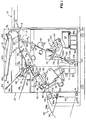
- is a front elevational view, in cross-section, of the modular finisher according to this invention, with portions shown schematically, removed, or broken away to facilitate viewing;
- Fig. 2
- is a view in perspective of the support tray of the stapling module of the modular finisher;
- Figs. 3a and 3b
- are plan and front elevational views respectively of a sheet folded by the Z-folder of the modular finisher;
- Figs. 4a and 4b
- are front and side elevational views respectively of an alternate embodiment of the folding nip roller pairs and knife blade of the folding mechanism for the saddle stitcher of the modular finisher apparatus according to this invention;
- Fig. 5
- is a top plan view of the folding mechanism of the saddle stitcher of the modular finisher according to this invention, with portions removed or broken away to facilitate viewing;
- Figs. 6a to 6c
- are rear elevational views of the folding mechanism of the saddle stitcher, in cross-section and with portions removed or broken away, respectively taken along the lines designated 6a-6a, 6b-6b, and 6c-6c of Fig. 5, and
- Fig. 7
- is a side elevational view of the compression assembly of the saddle stitcher folding mechanism.
- Referring now to the accompanying drawings, Fig. 1 shows the improved modular finisher apparatus according to the saddle stitcher of this invention, designated generally by the
numeral 10. Thefinisher apparatus 10 may be associated with an electrostatographic copier or copier/duplicator, a thermal or electronic printer, or a photographic printer, or any other like reproduction apparatus. The reproduction apparatus of the illustrated embodiment, shown only in part in Fig. 1, is designated generally by thenumeral 12. The purpose of themodular finisher 10 is to efficiently finish reproduction sets from any conventional well known reproduction apparatus to form completely finished reproduction sets of a desired configuration at a speed which makes maximum use of the speed of the reproduction apparatus. As used herein, the term "reproduction sheets" refers to sheets bearing information reproduced in any well known manner by the reproduction apparatus or other sheets inserted into a reproduction set, such as for example blank sheets, cover sheets or tab stock; and the term "reproduction sets" refers to a plurality of reproduction sheets which when viewed together make up a copy corresponding to a multi-page original information bearing document. - The timing and control of the various operative components of the
modular finisher apparatus 10 with respect to each other and to the reproduction apparatus are controlled by a logic and control unit C including a microprocessor for example. The microprocessor receives input and timing signals from sensors (not shown) located at points in the paths of sheets through the finisher and associated with the components of the finisher. Based on such signals and a program for the microprocessor, the unit C produces signals to control the operation of the various components of the finisher. The production of a program for commercially available microprocessors suitable for use with this invention is a conventional skill well understood in the art. The particular details of any such program would, of course, depend on the architecture of the selected microprocessor. - Typical high productivity reproduction apparatus reproduce information on individual sheets in a precollated manner so that the sheets upon exiting the apparatus (at
chute 14 in the illustrated embodiment) may be readily grouped into reproduction sets. To provide precollated reproduction sets of information contained in a document sheet stack, the reproduction apparatus may include a recirculating document feeder of the type described in the aforementioned US-A-4,169,674, operating to recirculate document sheets from a document sheet stack seriatim from the stack of document sheets to an exposure station of a reproduction apparatus for copying and then returned to such stack, in order, a number of times equal to the desired number of reproductions to be made of such stack. Alternatively, such as with reproduction apparatus including a mechanism for capturing or creating information electronically, information can be electronically acquired and saved in a memory storage device to thereafter be recalled at a desired time to form the desired number of multiple precollated reproductions sets. - As noted above, the production of precollated reproduction sets enables the ready production of completely finished reproduction sets to markedly improve the overall productivity of the reproduction system. The
finisher 10 according to this invention, constructed to provide a device in modular form which can accomplish the production of completely finished reproduction sets in a selectable variety of forms, includes an upper transport module 20, astapling module 30, and anoutput hopper 50. Additionally, the finisher has provisions for optional auxiliary devices selected from the group including a Z-folder 70, asaddle stitcher 90, and aninsert tray 150. By its unique construction, themodular finisher 10 according to this invention can readily accommodate any combination of the optional auxiliary devices. - The upper transport module 20 of the
finisher 10 is incorporated in a self-containedhousing 22 having a first transport path P1. The transport path P1 is defined, for example, by wire-form or sheet metal guides and driven nip rollers located at appropriately spaced intervals with respect to the guides. The upper transport module 20 is positioned such that the entrance E to the path P₁ is adjacent to thechute 14 of thereproduction apparatus 12. In this manner, the information-bearing reproduction sheets of a reproduction set exiting theapparatus 12 are received seriatim in the path P₁ and directed under normal operating circumstances to a sheet delivery station 24. - The sheet delivery station 24 (which may be for example of the type shown and described in US-A-4,930,765, issued June 5, 1990, in the name of Russel et al) directs the received sheets of a reproduction set to the
stapling module 30. - Under certain circumstances, it may be desired to review a full reproduction set prior to accomplishing finishing operations thereon. Accordingly, the upper transport module 20 also includes a bypass transport path P1A similarly defined by wire-form or sheet metal guides and spaced driven nip rollers. In path P1A, sheets are directed to a proof set
hopper 26 readily accessible to an operator for retrieval and review. If, after review, the proof set is found to be in the desired condition ready for finishing, thediverter 28 is returned to its normal position so that sheets constituting the second reproduction set (and all subsequently produced reproduction sets) are directed to the sheet delivery station. - The stapling module includes a
tray 34 positioned to accept the sheets making up a full reproduction set from the sheet delivery station 24 of the upper transport module 20. The sheets of the reproduction set, delivered seriatim through the station 24, are respectively corner registered on thetray 34 against a registration gate 36a selectively located to intercept the reproduction set travel path and anedge guide 36b at right angles to the gate. Such corner registration may be effected for example by a rotatingflexible disk jogger 38, or any other well known mechanism which can urge the individual sheets of the reproduction set in a direction perpendicular to sheet travel against the gate and edge guide. As illustrated in Fig. 2, a sheet S is moved in mutually perpendicular directions respectively by thejogger 38, rotating in the direction of its associated arrow, and under the influence of gravity, in the general direction of sheet travel. The sheet S thus moves from its solid line position through its broken line position into the corner formed by gate 36a andedge guide 36b. - Once all of the sheets making up the full reproduction set are properly corner registered, a stapling
assembly 40 controlled by unit C is activated to place staples at a desired location (or plurality of locations) along the lead edge of the reproduction set registered against the gate 36a. An exemplary stapling assembly is shown and described in US-A-4,903,952, issued Feb. 27, 1990, in the name of Russel et al. After the reproduction set has been stapled by the staplingassembly 40, the registration gate 36a is moved to a remote location (out of the travel path for the stapled reproduction set) and an ejector roller 48 urges the stapled set from thetray 34 toward theoutput hopper 50. - The
output hopper 50 is attached to thehousing 32 adjacent to an external wall thereof. An entrance slot 52 in the external housing wall provides for communication between theoutput hopper 50 and thestapling module 30. As such, stapled reproduction sets (or alternatively sets which pass directly through the stapling module without being stapled) are directed to the output hopper and stacked for ready operator retrieval. A pair offoam rollers 54 urge the reproduction sets toward atray 56 angled from the horizontal in an "up hill" direction relative to the path of the incoming reproduction sets. Therollers 54 are of a relatively large diameter foam construction to enable the rollers to handle a wide variety of thicknesses of reproduction sets. A pair ofdangler arms tray 56. - A plurality of fingers 62 (one shown in Fig. 1) are movable under the control of unit C to a remote position (broken line) relative to the incoming reproduction sets as a set is being registered against the
guide plate 60, and to a position (solid line) overlying the set stack once a set has been registered. Thefingers 62 are spring urged for example to apply a downward force on the stack of reproduction sets on thetray 56 to hold the set stack against theguide plate 60 thereby substantially preventing dishevelment of the stack. - The elevation of the
tray 56 is controlled by anelevator mechanism 64 of any suitable type, such as for example a spring-urged support, a rotating screw thread, a chain drive or the like. Thetray 56 is lowered by theelevator mechanism 64 as reproduction sets are delivered and stacked on the tray. Further, a motor M connected to theoutput hopper 50 selectively reciprocates the hopper in a direction cross-track relative to the path of incoming reproduction sets delivered to thetray 56. The timing of reciprocation of the output hopper is selected such that sequentially received reproduction sets are offset for ease of separation and removal from the tray by an operator. - Turning now to the optional auxiliary devices, the the module defining the Z-
folder 70 will first be described. The Z-folder 70 is for the express purpose of folding large individual sheets into a reduced overall size where the folded sheets can be included for example in a booklet or stack with other smaller sized sheets. As an illustrative example, a 279 mm x 432 mm (11"x17") sheet is folded so that its overall dimensions are 279 mm x 216 mm (11"x8 1/2") (see Figs. 3a, 3b) for inclusion in a reproduction set with basic overall dimensions of 279 mm x 216 mm (11"x8 1/2"). The Z-folder 70 includes a driven cluster ofrotating rollers 72 andsheet guide chutes rollers 72 and guidechutes frame 82 readily receivable in thehousing 22 of the upper transport module 20 on cooperating slide guides 84 for example. In this manner, if it is desired to include a Z-folder in thefinisher 10, a Z-folder module is merely slid into place in the finisher. - When it is desired to effect folding of a sheet, such sheet is transported along the path P1A and then directed by a
diverter 78 into the path P1B. Thediverter 78 is controlled for example by a solenoid actuator for movement to a position (solid line position of Fig. 1) for directing sheets along the path P1A to the Z-folder 70 or to a position (broken line position of Fig. 1) for directing sheets to the proof sethopper 26. - In the folding operation ion the Z-
folder 70, a sheet Z in the path P is urged into the nip between rotating roller 72a, driven by a motor to become a driving roller, and idler roller 72b of the roller cluster 72 (see Fig. 4a). The roller pair 72a, 72b urge the sheet into theupper chute 74 until the lead edge of the sheet engages an adjustable stop 74a. - The sheet Z, with the first fold F₁ now being the leading edge, continues to be driven into the
chute 76 until such new lead edge engages the stop 76a. Similarly to the action described above relative to accomplishing the first fold F₁, the stop 76a prevents the sheet from moving further into thechute 76. The urging of the sheet Z by the rollers 72a and 72c thus causes the sheet to buckle and be fed into the second fold nip between the rollers 72a and 72d. The second fold F₂ is then formed by the rollers 72a and 72d, and the folded sheet is thereafter urged by such rollers in a direction out of the Z-folder opposite to its incoming direction. - The module defining the
saddle stitcher 90 of themodular finisher 10 according to this invention is for the purpose of providing the finisher with the capability of making center stapled and folded booklets. Thesaddle stitcher 90 has five major components: a transport path P₃, astapling mechanism 92, afolding mechanism 94,anedge registration assembly 96, and a booklet-receivingoutput hopper 98. As with the optional Z-folder module 70, the major components of the saddle stitcher are readily receivable in thefinisher 10. Particularly, the major components are, for example, slidably receivable on cooperating slide guides 100 in thehousing 32. In this manner, if it is desired to include asaddle stitcher module 90 in thefinisher 10, the components of the saddle stitcher module are merely received in place in the finisher. - The transport path P₃ for the
saddle stitcher 90 is located such that it communicates with the path P₁ of the upper transport module 20 downstream, in the direction of sheet travel, from thediverter 28. Adiverter 102, associated with the path P₃, is movable for example by a solenoid actuator to a position (solid line position of Fig. 1) remote from the path P₁, or to a position (broken line position of Fig. 1) intercepting the path P₁ to direct sheets into the path P₃. Sheets received seriatim in the path P₃ are aligned in the cross-track direction by a jogger mechanism 104 (similar for example to thejogger 38 associated with the stapling module 30). - The lead edges of the respective cross-track aligned sheets comprising a reproduction set are registered against a
first gate 106 of theregistration assembly 96 located to intercept the path P₃. In order to accommodate for formation of neat booklets from reproduction sets of various overall dimensions, thegate 106 must be adjustable along the path P₃ to properly locate the center staples for the booklets. Accordingly, thegate 106 is mounted on asupport 106a adjustable along aslide bar 106b in the direction of sheet travel (i.e., the direction ofarrow 106c in Fig. 1). Adjustment of thesupport 106a positions thefirst gate 106, when in its path intercepting position, to locate the lead edges of the delivered sheets at a preselected distance from the stapling line defined by thestapling mechanism 92. Such preselected distance is desirably substantially equal to one-half the dimension of the sheets in the sheet travel direction. - Once the requisite number of sheets for completing a full reproduction set have been delivered to the
saddle stitcher module 90, thestapling mechanism 92 thereof is actuated by the control unit C to staple the reproduction set along the stapling line, substantially corresponding to the center line of the sheets in the sheet travel direction. After stapling has been accomplished, thegate 106 is pulled out of the path P₃ by asolenoid actuator 106s enabling the stapled reproduction set to continue its travel in the path P₃ under the influence of gravity for example. The stapled reproduction set continues its travel until the lead edge thereof is registered against asecond gate 108 located to intercept the path P₃ downstream of thegate 106. - The
gate 108 is adjustable in the direction of sheet travel to locate the lead edges of the delivered stapled reproduction set sheets at a preselected distance from the folding line defined by thefolding mechanism 94. Such preselected distance is desirably substantially equal to one-half the dimension of the sheets in the sheet travel direction- Another way of looking at the adjustable placement of thegate 108 is that thegate 108 should be located a distance from thegate 106 substantially equal to the distance between the stapling line defined by thestapling mechanism 92 and the folding line defined by thefolding mechanism 94. In this manner, when the stapled reproduction set is delivered to thegate 108, the established folding line will correspond to the stapling line such that folding accomplished by themechanism 94 occurs on the center line of the sheets in the sheet travel direction resulting in formation of a neat booklet from the reproduction set. - As is apparent, the distance between the staple line as defined by the
stapling mechanism 92 and the folding line as defined by thefolding mechanism 94 is fixed. Accordingly, any adjustment of thefirst gate 106 necessitates a similar (substantially equal) adjustment of thesecond gate 108. Therefore, for the simplicity of construction and convenience of operation, the adjustability of thesecond gate 108 may be accomplished by connecting the second gate to thesupport 106a for the first gate for movement therewith to provide simultaneous corresponding adjustment of the gates. - The
folding mechanism 94 includes aknife blade 110 selectively actuatable into cooperative relation with a double set of folding niprollers 112. As more particularly shown in Figs. 5 and 6a-6c, theknife blade 110 is supported by abar 114 which is, in turn, mounted for reciprocation inlinear slides 116 provided respectively in spacedframe plates 118. Theslides 116, made from a friction reducing material, are aligned with the folding nip roller pairs 112 to accurately guide theknife blade 110 between the rollers on reciprocation of the blade. Theindividual rollers 112a-112d, which comprise the folding nip roller pairs 112, are designed to maintain significant structural rigidity under load to minimize deflection. For example, the rollers may respectively be constructed as a solid aluminum core coated with rubber with steel shafts knurled and pressed into the bored ends thereof. Thelower rollers frame plates 118, while theupper rollers frame plates 118 respectively bypivot pins 118b located downstream (in the direction of sheet travel) from the folding nip roller pairs. Accordingly, sheets being folded are urged by theknife blade 110 through one roller nip (i.e., between therollers rollers - In order to accomplish neat folding of the sheets of the reproduction set, it is necessary to provide a desired predetermined engagement force between the rollers of the folding roller nip
pairs 112 as the sheets of the reproduction set are urged therebetween. Accordingly, acompression assembly 120 is provided. The compression assembly 120 (best shown in Figs. 5, 6c, and 7) includes anupper anchor bar 120a interconnected between theframe plates 118 and alower anchor bar 120b interconnected between the subframe plates 118a. A pair of compression springs 122 are retained between theupper anchor bar 120a and thelower anchor bar 120b bylong bolts 124. The long bolts are guided in bearings in the upper anchor bar and are threaded to the lower anchor bar to maintain a predetermined preload force between the bars and thus between the associated structure including, ultimately, the nip roller pairs 112. The attachment of the upper and lower anchor bars to the frame plates and subframe plates respectively are by way of pivot pins 126. The pivot pins 126 enable the anchor bars 120a, 120b to pivot relative to theframe plates 118 and thesubframe plates 118b in order to prevent binding of thelong bolts 124 as thesprings 122 compress during the folding operation. - The provision of folding nip roller pairs 112 offers several significant advantages in the operation of the
folding mechanism 94. Due to the location of the compression springs 122 of thecompression assembly 120 relative to the nip roller pairs 112 and the pivotal relationship between the upper rollers and lower rollers of the nip roller pairs, a different mechanical advantage is exhibited at each of the nip roller pairs. Specifically, the mechanical advantage at the second nip roller pair (rollers rollers frame plates 118. Therefore, the greater force-applying second nip roller pair is already somewhat spread apart to readily receive the reproduction set being folded to complete the folding operation. With this arrangement then, the first nip roller pair is thus wedged open with a relatively light (non-damaging to the reproduction set) force irrespective of the thickness of the reproduction set being folded, and the second nip roller pair is accordingly partially opened by the set passing through the first nip roller pair. As a result, thefolding mechanism 94 is effectively operational to automatically fold reproduction sets of various thicknesses without the need for a nip gap adjustment mechanism as would be required to accommodate various reproduction set thicknesses when only one nip roller pair is utilized to accomplish the folding operation. - In order to effect selective reciprocation of the
knife blade 110, under the control of unit C, thefolding mechanism 94 of thesaddle stitcher 90 includes amotor 130 having an output shaft 130a (see Fig. 6c). The output shaft 130a is drivingly connected to amain pulley 132a of a belt-and-pulley drive arrangement 132 (see Fig. 6b). A plurality of elements of thedrive arrangement 132 are coupled respectively to therollers 112a-112d of the folding roller nippairs 112 to continuously rotate the rollers. Further, elements of thedrive arrangement 132 are coupled to drivegears 134, fixedly mounted on across shaft 134a, through aclutch mechanism 136 to rotate the cross shaft (and thus the drive gears) on actuation of the clutch mechanism. The drive gears 134 mesh with cranks 138 (see Fig. 6a) which havelinks 140 pivotably connected at their respective ends to the cranks and the knifeblade support bar 114. - A switch (not shown) of any well known type detects the angular position of the
cranks 138 and provides a signal for the control unit C to effect actuation of theclutch mechanism 136. Such clutch mechanism actuation occurs for one revolution of thecranks 138 so that for each reproduction set to be folded, theknife blade 110 is reciprocated through one complete stroke. A complete stroke of theknife blade 110 contemplates travel of the blade a distance sufficient to urge the reproduction set being folded completely through thefolding mechanism 94 and out of the nip roller pairs 112 where the formed booklet falls under the influence of gravity into theoutput hopper 98. Thehopper 98 is mounted in thehousing 32 of themodular finisher 10 onslides 98a so as to enable the hopper to move to a convenient location, for example external to the housing, to facilitate operator retrieval of the folded booklets collected in the hopper. - In one embodiment of the
saddle stitcher 90 according to this invention, thelinks 140 are of somewhat different lengths. Accordingly, the angle of theknife blade 110 relative to the folding nip roller pairs 112 changes during the reciprocation of the knife blade. As a result, the reproduction set being folded is sent into the nips of the roller pairs at a skewed angle (rather than squarely with respect to the nips) so that the edge being folded does not contact the nip rollers all at once. Rather, the fold is effected sequentially in the direction of the fold during a segment of the travel distance of the reproduction set through the nip. This results in a tighter fold than can be accomplished when the fold is produced all at once (for a given nip pressure), and reduces the noise and power to complete the fold. - In another embodiment of the saddle stitcher according to this invention, the rollers of the folding nip roller pairs have a plurality of under-cut portions for accepting a complementary shaped knife blade. As shown in Figs. 8a and 8b, an exemplary roller pair designated by the numeral 112' has undercut
portions 142. Such under-cut portions readily receivecomplementary portions 144 of the knife blade 110' in a substantially non-contacting manner. With such arrangement, the the angle of the knife blade to the nip roller pairs can be kept square, thus assuring a square fold in forming the reproduction set into a folded booklet, and the force on the roller pairs to effect folding is substantially independent of the insertion of the knife blade therebetween. - Turning now to the module defining the insert tray 150 (shown in Fig. 1), the insert tray is for the purpose of providing the
modular finisher 10 according to this invention with the ability to selectively add additional sheets to a reproduction set. For example the additional sheets may be preprinted cover sheets of the same or different stock characteristics to the sheets of the reproduction set, or may be sheets utilized within a reproduction set to separate distinct portions of the set. Theinsert tray 150 includes asheet receiving hopper 152 removably locatable in thetop cover 154 for thefinisher 10. Thehopper 152 has appropriate guides (not shown) for aligning a stack of sheets therein relative to asheet feed device 156. Thesheet feed device 156, of any well known type such as a scuff feeder or a vacuum feeder for example, is activated by the control unit C when it is desired to selectively feed a single sheet from thehopper 152 to have such sheet inserted into a reproduction set being received by thefinisher 10. The sheet is fed into a transport path P₄ communicating with the transport path P₁ of the upper transport module 20 between the entrance E and thediverter 28. Accordingly, the additional sheet is selectively inserted into the path P₁ at a desired time during the finishing of a reproduction set to be treated the same as any other sheet in the set during the finishing operation.
Claims (14)
- Saddle stitcher apparatus (90) for forming completely finished reproduction sets of a series of reproductions produced on sheets respectively by a reproduction apparatus (12), said saddle stitcher (90) including means for receiving (P₃), collecting (96), stapling (92) and folding (94) reproduction sheets, characterized in that said saddle stitcher (90) is one of a group of modular devices (30, 50, 70, 90, 150) of a modular finisher apparatus (10), said saddle stitcher (90) including a support frame (118), said frame including means (100) for mating with means for detatchably accepting the said saddle stitcher with a housing (32) of the modular finisher apparatus (10), means associated with said support frame (118) for defining a sheet feed path (P₃) communicating with reproduction sheet receiving means (E), means (96) mounted on said frame (118) for registering reproduction sheets, means (92) associated with said frame for stapling registered reproduction sheets at substantially the mid-line thereof to form a reproduction set, means (94) for folding a stapled reproduction set substantially along the mid-line thereof, and an output hopper (98) for collecting folded stapled reproduction sets.
- The saddle stitcher apparatus of Claim 1 characterized by said registration means (96) including a first gate (106), and means (106s) for selectively moving said first gate to a position intercepting the sheet feed path of said sheet feed path defining means to register reproduction sheets in preparation for stapling, and to a position remote from such path after stapling reproduction sheets into a reproduction set.
- The saddle stitcher apparatus of Claim 2 characterized by said registration means (96) further including means (106a) for adjustably supporting said first gate (106) on said frame (118) for movement in the direction (106c) of the sheet feed path of said sheet feed path defining means, whereby the location at which said first gate (106) of said registration means intercepts such sheet feed path can be adjusted in accordance with the dimension of reproduction sheets along such sheet feed path so that such reproduction sheets are registered at said first gate with the mid-line of such sheets aligned with said stapling means.
- The saddle stitcher apparatus of Claim 3 characterized in that said registration means (96) further includes a second gate (108) positioned to intercept the path of said sheet feed path defining means downstream of said first gate (106), in the direction of travel of the reproduction sheets, at a location whereby, when said first gate (106) is moved to its remote position, the lead edge of a stapled reproduction set is moved to engage and be registered by said second gate (108) at a position where the mid-line of said stapled reproduction set is aligned with said folding means (94).
- The saddle stitcher apparatus of Claim 4 characterized in that said second gate (108) is interconnected with said first gate (106) so as to move therewith as said first gate is adjusted to similarly adjust said second gate.
- The saddle stitcher apparatus of Claim 1 characterized in that said folding means (94) includes an elongated knife blade (110) and a plurality of pairs of nip rollers (112), said knife blade (110) arranged to urge a stapled reproduction set sequentially through said pairs of nip rollers (112) and then into said output hopper (98).
- The saddle stitcher apparatus of Claim 6 characterized in hat said knife blade (110) is mounted for reciprocation in a direction transverse to the sheet feed path (P₃) of said sheet feed path defining means, said knife blade lying in a plane passing through the mid-line of a stapled reproduction set and the nips of said pairs of nip rollers (112).
- The saddle stitcher apparatus of Claim 7 characterized in that said folding means (94) includes means (130) for reciprocating said knife blade (110) in said plane at an angle to the nip line of said pairs of nip rollers (112) to pass through said nips thereof progressively, whereby the fold in a reproduction set is effected sequentially in the direction of the fold during a segment of the travel distance of such reproduction set through said nips.
- The saddle stitcher apparatus of Claim 8 characterized in that said reciprocating means (130) includes a rotatable drive shaft (130a), at least one crank (138) rotatably driven by said drive shaft, at least one link (140) connected to said at least one crank (138) at one end and connected at its opposite end to said knife blade (110).
- The saddle stitcher apparatus of Claim 9 characterized in that said reciprocating means (130) includes a motor having a rotating output shaft, clutch means (136) for selectively coupling said motor output shaft to said drive shaft, and control means for actuating said clutch means to couple said output shaft to said drive shaft for a time sufficient to rotate said crank (138) through one revolution to effect one reciprocation cycle for said knife blade (110).
- The saddle stitcher apparatus of Claim 10 characterized in that said reciprocating means includes a pair of cranks (138) and a pair of links (140) associated respectively therewith, said links being connected to opposite ends of said elongated knife blade (110), with one link being longer than the other link.
- The saddle stitcher apparatus of Claim 7 characterized in that said folding means (94) includes a subframe (118a), and means (120) for urging said subframe (118a) toward said frame (118); and wherein one roller (112b, 112d) of each of said plurality of pairs of nip rollers (112) is supported in said frame (118), and the other roller (112a, 112c) of each of said plurality of pairs of nip rollers is supported in said subframe (118a).
- The saddle stitcher apparatus of Claim 12 characterized in that said folding means (94) includes a pivot pin (118b) for pivotably connecting said subframe (118a) to said frame (118), said pivot pin is located downstream, in the direction of travel of a reproduction set being folded, from said plurality of pairs of nip rollers (112), and said urging means (120) is located upstream, in the direction of travel of a reproduction set being folded, from said plurality of pairs of nip rollers, whereby a progressively increasing mechanical advantage is exhibited at each of said nip roller pairs (112a, 112b; 112c, 112d).
- The saddle stitcher apparatus of Claim 6 characterized in that said output hopper (98) is selectively movable to a location to collect folded reproduction sets exiting said plurality of pairs of nip rollers (112) of said folding means, and to a remote location where removal of collected folded reproduction sets from said output hopper is facilitated.
Applications Claiming Priority (7)
| Application Number | Priority Date | Filing Date | Title |
|---|---|---|---|
| US636785 | 1991-01-02 | ||
| US636792 | 1991-01-02 | ||
| US07/636,792 US5108081A (en) | 1991-01-02 | 1991-01-02 | Saddle stitcher for a reproduction apparatus finisher |
| US636786 | 1991-01-02 | ||
| US07/636,786 US5080340A (en) | 1991-01-02 | 1991-01-02 | Modular finisher for a reproduction apparatus |
| US07/636,785 US5108082A (en) | 1991-01-02 | 1991-01-02 | Z-folder for a reproduction apparatus finisher |
| EP92903799A EP0517903B1 (en) | 1991-01-02 | 1991-12-19 | Modular finisher for a reproduction apparatus |
Related Parent Applications (2)
| Application Number | Title | Priority Date | Filing Date |
|---|---|---|---|
| EP92903799A Division EP0517903B1 (en) | 1991-01-02 | 1991-12-19 | Modular finisher for a reproduction apparatus |
| EP92903799.2 Division | 1991-12-19 |
Publications (3)
| Publication Number | Publication Date |
|---|---|
| EP0676302A2 true EP0676302A2 (en) | 1995-10-11 |
| EP0676302A3 EP0676302A3 (en) | 1995-11-08 |
| EP0676302B1 EP0676302B1 (en) | 1998-11-25 |
Family
ID=27417599
Family Applications (2)
| Application Number | Title | Priority Date | Filing Date |
|---|---|---|---|
| EP92903799A Expired - Lifetime EP0517903B1 (en) | 1991-01-02 | 1991-12-19 | Modular finisher for a reproduction apparatus |
| EP95106413A Expired - Lifetime EP0676302B1 (en) | 1991-01-02 | 1991-12-19 | Saddle stitcher apparatus for a modular finisher apparatus |
Family Applications Before (1)
| Application Number | Title | Priority Date | Filing Date |
|---|---|---|---|
| EP92903799A Expired - Lifetime EP0517903B1 (en) | 1991-01-02 | 1991-12-19 | Modular finisher for a reproduction apparatus |
Country Status (4)
| Country | Link |
|---|---|
| EP (2) | EP0517903B1 (en) |
| JP (1) | JP3269557B2 (en) |
| DE (2) | DE69118522T2 (en) |
| WO (1) | WO1992012087A1 (en) |
Families Citing this family (8)
| Publication number | Priority date | Publication date | Assignee | Title |
|---|---|---|---|---|
| US5449157A (en) * | 1993-02-08 | 1995-09-12 | Konica Corporation | Recording sheet finishing apparatus |
| NL1000855C2 (en) * | 1995-07-20 | 1997-01-21 | Oce Nederland Bv | Device for collecting folded and unfolded copy sheets. |
| FR2739846B1 (en) * | 1995-10-12 | 1997-12-19 | C P Bourg Sa | BOOKLET FINISHING MACHINE |
| DE69608227T2 (en) * | 1995-12-28 | 2001-01-04 | Canon Aptex K K | Apparatus for folding sheets |
| US7450881B2 (en) * | 2002-04-18 | 2008-11-11 | Krdc Co., Ltd. | Finishing apparatus of image forming apparatus |
| US7207557B2 (en) * | 2003-06-04 | 2007-04-24 | Konica Minolta Business Technologies, Inc. | Image forming system and single-sheet processing machine |
| US8636431B2 (en) | 2009-08-26 | 2014-01-28 | Provo Craft And Novelty, Inc. | (Moab omnibus-apparatus) crafting apparatus including a workpiece feed path bypass assembly and workpiece feed path analyzer |
| JP5394863B2 (en) | 2009-09-09 | 2014-01-22 | ニスカ株式会社 | Sheet folding apparatus and image forming system provided with the same |
Citations (11)
| Publication number | Priority date | Publication date | Assignee | Title |
|---|---|---|---|---|
| DE68459C (en) * | Firma MASCHINENFABRIK HEIDELBERG, MO-LITOR & ClE, in Heidelberg | Wire stitching machine connected to a folding device | ||
| US4134672A (en) * | 1976-03-30 | 1979-01-16 | Eastman Kodak Company | Copier finisher for an electrographic reproducing device |
| US4169674A (en) * | 1974-11-13 | 1979-10-02 | Eastman Kodak Company | Recirculating sheet feeder |
| US4270742A (en) * | 1978-03-27 | 1981-06-02 | Hiroshi Kobayashi | Paper stack binding and folding device |
| US4410170A (en) * | 1980-07-10 | 1983-10-18 | Bruce Wertheimer | Machine for stapling and folding a stack of paper sheets to form a book |
| US4509732A (en) * | 1979-02-24 | 1985-04-09 | Ricoh Company, Ltd. | Document handling apparatus for producing folded and bound stacks of documents |
| US4592651A (en) * | 1984-05-10 | 1986-06-03 | Ricoh Company, Ltd. | Copier with bookbinding function |
| US4595187A (en) * | 1985-07-26 | 1986-06-17 | Xerox Corporation | Saddle stapler accessory |
| US4903952A (en) * | 1988-08-29 | 1990-02-27 | Eastman Kodak Company | Finisher apparatus |
| US4917364A (en) * | 1985-03-15 | 1990-04-17 | Canon Kabushiki Kaisha | Sheet processing apparatus |
| US4930765A (en) * | 1988-12-27 | 1990-06-05 | Eastman Kodak Company | Sheet collection mechanism for stacking long and short sheets |
Family Cites Families (13)
| Publication number | Priority date | Publication date | Assignee | Title |
|---|---|---|---|---|
| JPS51193A (en) * | 1974-06-08 | 1976-01-05 | Yasumata Kure | CHIBUSAI KUSEIKI |
| JPS5444746A (en) * | 1977-09-14 | 1979-04-09 | Matsushita Electric Works Ltd | Multilayer contact structure |
| JPS54145273A (en) * | 1978-04-29 | 1979-11-13 | Michiharu Murota | Roasting apparatus |
| US4313670A (en) * | 1979-10-30 | 1982-02-02 | Xerox Corporation | Reproduction machine with a pivotal stapling device |
| DE3234746A1 (en) * | 1982-09-20 | 1984-03-22 | Agfa-Gevaert Ag, 5090 Leverkusen | SORTING COPY TRAY |
| US4603971A (en) * | 1984-09-17 | 1986-08-05 | Xerox Corporation | Finisher mode switching |
| US4717134A (en) * | 1985-03-15 | 1988-01-05 | Canon Kabushiki Kaisha | Sheet folding apparatus |
| US4917366A (en) * | 1986-02-25 | 1990-04-17 | Canon Kabushiki Kaisha | Sheet handling apparatus |
| US4878656A (en) * | 1987-03-20 | 1989-11-07 | Canon Kabushiki Kaisha | Sheet finisher |
| DE68919915T2 (en) * | 1988-06-14 | 1995-05-04 | Canon Kk | Sheet post-processing device. |
| US4871158A (en) * | 1989-02-27 | 1989-10-03 | Xerox Corporation | Very high speed duplicator with finishing function |
| US5083760A (en) * | 1989-04-18 | 1992-01-28 | Ricoh Company, Ltd. | Finisher for an image forming apparatus |
| US5007625A (en) * | 1989-08-24 | 1991-04-16 | Xerox Corporation | Selectable sheet offsetting |
-
1991
- 1991-12-19 DE DE69118522T patent/DE69118522T2/en not_active Expired - Fee Related
- 1991-12-19 WO PCT/US1991/009526 patent/WO1992012087A1/en active IP Right Grant
- 1991-12-19 EP EP92903799A patent/EP0517903B1/en not_active Expired - Lifetime
- 1991-12-19 DE DE1991630540 patent/DE69130540T2/en not_active Expired - Fee Related
- 1991-12-19 EP EP95106413A patent/EP0676302B1/en not_active Expired - Lifetime
- 1991-12-19 JP JP50382892A patent/JP3269557B2/en not_active Expired - Fee Related
Patent Citations (11)
| Publication number | Priority date | Publication date | Assignee | Title |
|---|---|---|---|---|
| DE68459C (en) * | Firma MASCHINENFABRIK HEIDELBERG, MO-LITOR & ClE, in Heidelberg | Wire stitching machine connected to a folding device | ||
| US4169674A (en) * | 1974-11-13 | 1979-10-02 | Eastman Kodak Company | Recirculating sheet feeder |
| US4134672A (en) * | 1976-03-30 | 1979-01-16 | Eastman Kodak Company | Copier finisher for an electrographic reproducing device |
| US4270742A (en) * | 1978-03-27 | 1981-06-02 | Hiroshi Kobayashi | Paper stack binding and folding device |
| US4509732A (en) * | 1979-02-24 | 1985-04-09 | Ricoh Company, Ltd. | Document handling apparatus for producing folded and bound stacks of documents |
| US4410170A (en) * | 1980-07-10 | 1983-10-18 | Bruce Wertheimer | Machine for stapling and folding a stack of paper sheets to form a book |
| US4592651A (en) * | 1984-05-10 | 1986-06-03 | Ricoh Company, Ltd. | Copier with bookbinding function |
| US4917364A (en) * | 1985-03-15 | 1990-04-17 | Canon Kabushiki Kaisha | Sheet processing apparatus |
| US4595187A (en) * | 1985-07-26 | 1986-06-17 | Xerox Corporation | Saddle stapler accessory |
| US4903952A (en) * | 1988-08-29 | 1990-02-27 | Eastman Kodak Company | Finisher apparatus |
| US4930765A (en) * | 1988-12-27 | 1990-06-05 | Eastman Kodak Company | Sheet collection mechanism for stacking long and short sheets |
Also Published As
| Publication number | Publication date |
|---|---|
| EP0676302B1 (en) | 1998-11-25 |
| EP0676302A3 (en) | 1995-11-08 |
| JP3269557B2 (en) | 2002-03-25 |
| DE69130540T2 (en) | 1999-06-17 |
| EP0517903A1 (en) | 1992-12-16 |
| DE69118522T2 (en) | 1996-10-31 |
| DE69130540D1 (en) | 1999-01-07 |
| DE69118522D1 (en) | 1996-05-09 |
| WO1992012087A1 (en) | 1992-07-23 |
| EP0517903B1 (en) | 1996-04-03 |
| JPH05505154A (en) | 1993-08-05 |
Similar Documents
| Publication | Publication Date | Title |
|---|---|---|
| US5080340A (en) | Modular finisher for a reproduction apparatus | |
| US5108082A (en) | Z-folder for a reproduction apparatus finisher | |
| CN100473596C (en) | Sheet processing apparatus and image forming apparatus provided with the same | |
| US5108081A (en) | Saddle stitcher for a reproduction apparatus finisher | |
| KR100262915B1 (en) | Document handler with a staple mode. | |
| DE69916748T2 (en) | Folding device for an image forming device | |
| US7562866B2 (en) | Sheet processing apparatus and image forming apparatus | |
| US7111837B2 (en) | Image forming apparatus integrating sheet postprocessing apparatus | |
| US7052005B2 (en) | Sheet postprocessing apparatus for use with image forming apparatus and folding method | |
| EP1400864A2 (en) | Binding apparatus, paper processing apparatus and image forming system | |
| JP3786568B2 (en) | Positioning paper in a curved paper path | |
| US7261288B2 (en) | Postprocessing apparatus with two or more finishing devices | |
| JP2000084903A (en) | Stapling device | |
| JPS60657B2 (en) | Document feeder for photocopier | |
| US6868253B2 (en) | Image forming apparatus which conveys an image-formed sheet to reverse the sheet and conveys the sheet to a folding unit when a three-fold process of folding a lower surface is selected | |
| EP0676302B1 (en) | Saddle stitcher apparatus for a modular finisher apparatus | |
| US5501442A (en) | Dual mode tamper/offsetter | |
| US6592113B1 (en) | Sheet post-processing apparatus | |
| JP3564192B2 (en) | Paper post-processing equipment | |
| JP2003261258A (en) | Paper processor and image forming system | |
| JP2004018161A (en) | Paper post-processing device | |
| JPS60258065A (en) | Paper folder in copying machine provided with bookbinding function | |
| JP4013349B2 (en) | Sheet binding device | |
| JP3645009B2 (en) | Post-processing equipment | |
| JP3802172B2 (en) | Sheet post-processing device |
Legal Events
| Date | Code | Title | Description |
|---|---|---|---|
| PUAI | Public reference made under article 153(3) epc to a published international application that has entered the european phase |
Free format text: ORIGINAL CODE: 0009012 |
|
| PUAL | Search report despatched |
Free format text: ORIGINAL CODE: 0009013 |
|
| AC | Divisional application: reference to earlier application |
Ref document number: 517903 Country of ref document: EP |
|
| AK | Designated contracting states |
Kind code of ref document: A2 Designated state(s): DE GB |
|
| RHK1 | Main classification (correction) |
Ipc: G03G 15/00 |
|
| AK | Designated contracting states |
Kind code of ref document: A3 Designated state(s): DE FR GB |
|
| 17P | Request for examination filed |
Effective date: 19960411 |
|
| 17Q | First examination report despatched |
Effective date: 19970908 |
|
| GRAG | Despatch of communication of intention to grant |
Free format text: ORIGINAL CODE: EPIDOS AGRA |
|
| GRAG | Despatch of communication of intention to grant |
Free format text: ORIGINAL CODE: EPIDOS AGRA |
|
| GRAH | Despatch of communication of intention to grant a patent |
Free format text: ORIGINAL CODE: EPIDOS IGRA |
|
| RBV | Designated contracting states (corrected) |
Designated state(s): DE GB |
|
| GRAH | Despatch of communication of intention to grant a patent |
Free format text: ORIGINAL CODE: EPIDOS IGRA |
|
| GRAA | (expected) grant |
Free format text: ORIGINAL CODE: 0009210 |
|
| AC | Divisional application: reference to earlier application |
Ref document number: 517903 Country of ref document: EP |
|
| AK | Designated contracting states |
Kind code of ref document: B1 Designated state(s): DE GB |
|
| REF | Corresponds to: |
Ref document number: 69130540 Country of ref document: DE Date of ref document: 19990107 |
|
| PLBE | No opposition filed within time limit |
Free format text: ORIGINAL CODE: 0009261 |
|
| STAA | Information on the status of an ep patent application or granted ep patent |
Free format text: STATUS: NO OPPOSITION FILED WITHIN TIME LIMIT |
|
| 26N | No opposition filed | ||
| REG | Reference to a national code |
Ref country code: GB Ref legal event code: 732E |
|
| REG | Reference to a national code |
Ref country code: GB Ref legal event code: IF02 |
|
| PGFP | Annual fee paid to national office [announced via postgrant information from national office to epo] |
Ref country code: GB Payment date: 20021104 Year of fee payment: 12 |
|
| PG25 | Lapsed in a contracting state [announced via postgrant information from national office to epo] |
Ref country code: GB Free format text: LAPSE BECAUSE OF NON-PAYMENT OF DUE FEES Effective date: 20031219 |
|
| GBPC | Gb: european patent ceased through non-payment of renewal fee |
Effective date: 20031219 |
|
| PGFP | Annual fee paid to national office [announced via postgrant information from national office to epo] |
Ref country code: DE Payment date: 20051230 Year of fee payment: 15 |
|
| PG25 | Lapsed in a contracting state [announced via postgrant information from national office to epo] |
Ref country code: DE Free format text: LAPSE BECAUSE OF NON-PAYMENT OF DUE FEES Effective date: 20070703 |