EP0668662A1 - Receiver and repeater for spread spectrum communication - Google Patents
Receiver and repeater for spread spectrum communication Download PDFInfo
- Publication number
- EP0668662A1 EP0668662A1 EP94923066A EP94923066A EP0668662A1 EP 0668662 A1 EP0668662 A1 EP 0668662A1 EP 94923066 A EP94923066 A EP 94923066A EP 94923066 A EP94923066 A EP 94923066A EP 0668662 A1 EP0668662 A1 EP 0668662A1
- Authority
- EP
- European Patent Office
- Prior art keywords
- antenna
- output
- delay circuit
- spread
- circuit
- Prior art date
- Legal status (The legal status is an assumption and is not a legal conclusion. Google has not performed a legal analysis and makes no representation as to the accuracy of the status listed.)
- Withdrawn
Links
Images


Classifications
-
- H—ELECTRICITY
- H04—ELECTRIC COMMUNICATION TECHNIQUE
- H04B—TRANSMISSION
- H04B7/00—Radio transmission systems, i.e. using radiation field
- H04B7/14—Relay systems
-
- H—ELECTRICITY
- H04—ELECTRIC COMMUNICATION TECHNIQUE
- H04B—TRANSMISSION
- H04B7/00—Radio transmission systems, i.e. using radiation field
- H04B7/02—Diversity systems; Multi-antenna system, i.e. transmission or reception using multiple antennas
- H04B7/04—Diversity systems; Multi-antenna system, i.e. transmission or reception using multiple antennas using two or more spaced independent antennas
- H04B7/08—Diversity systems; Multi-antenna system, i.e. transmission or reception using multiple antennas using two or more spaced independent antennas at the receiving station
- H04B7/0891—Space-time diversity
- H04B7/0894—Space-time diversity using different delays between antennas
-
- H—ELECTRICITY
- H04—ELECTRIC COMMUNICATION TECHNIQUE
- H04B—TRANSMISSION
- H04B1/00—Details of transmission systems, not covered by a single one of groups H04B3/00 - H04B13/00; Details of transmission systems not characterised by the medium used for transmission
- H04B1/69—Spread spectrum techniques
- H04B1/707—Spread spectrum techniques using direct sequence modulation
- H04B1/7097—Interference-related aspects
- H04B1/711—Interference-related aspects the interference being multi-path interference
- H04B1/7115—Constructive combining of multi-path signals, i.e. RAKE receivers
- H04B1/712—Weighting of fingers for combining, e.g. amplitude control or phase rotation using an inner loop
-
- H—ELECTRICITY
- H04—ELECTRIC COMMUNICATION TECHNIQUE
- H04B—TRANSMISSION
- H04B7/00—Radio transmission systems, i.e. using radiation field
- H04B7/02—Diversity systems; Multi-antenna system, i.e. transmission or reception using multiple antennas
- H04B7/04—Diversity systems; Multi-antenna system, i.e. transmission or reception using multiple antennas using two or more spaced independent antennas
- H04B7/06—Diversity systems; Multi-antenna system, i.e. transmission or reception using multiple antennas using two or more spaced independent antennas at the transmitting station
- H04B7/0613—Diversity systems; Multi-antenna system, i.e. transmission or reception using multiple antennas using two or more spaced independent antennas at the transmitting station using simultaneous transmission
- H04B7/0667—Diversity systems; Multi-antenna system, i.e. transmission or reception using multiple antennas using two or more spaced independent antennas at the transmitting station using simultaneous transmission of delayed versions of same signal
- H04B7/0671—Diversity systems; Multi-antenna system, i.e. transmission or reception using multiple antennas using two or more spaced independent antennas at the transmitting station using simultaneous transmission of delayed versions of same signal using different delays between antennas
Definitions
- the present invention relates to a receiver and a repeater for spread-spectrum communications which improve diversity characteristics.
- the spread-spectrum communications such as CDMA (Code Division Multiple Access) performs a plurality of modulations at a transmitting side, and corresponding demodulations at a receiving side, thereby communicating information symbols. More specifically, the transmitting side transmits information symbols after performing a primary modulation, such as PSK, of the information symbols, and then, spreading the primary modulation signal into a wideband frequency range by performing a secondary modulation using a spreading code such as a high-rate pseudo-random code.
- a primary modulation such as PSK
- the receiving side performs despreading (secondary demodulation) using the same and synchronized spreading code with the transmitting side so that the wideband frequency received signal is inversely converted into the band of the information symbols, and then, carries out a primary demodulation corresponding to the primary modulation, thereby restoring the original information symbols.
- a signal transmitted from a base station or a mobile station will reflect from obstacles such as buildings or the like on its propagation paths. Accordingly, the signal is received as a multipath signal whose component waves (delayed waves) arrive at different times because individual delayed waves have different delay times on the propagation paths. If the variance of the delay times of the propagation paths is greater than one element length of a spreading code (one chip interval), fluctuations of the individual delayed wave components which are extracted at every chip interval can be handled as non-correlated quantity. In other words, the amplitude and phase of each delayed wave component can be considered to change independently.
- the average received level will be improved by combining the independent delayed wave components after making their phases coherent, or by selecting a delayed wave component whose amplitude is maximum.
- This idea is implemented as a well-known RAKE reception, wherein improvement in transmission characteristics can be expected owing to the path diversity receiving effect.
- Fig. 1 is a block diagram showing a conventional spread-spectrum communication receiver carrying out the path diversity reception (RAKE reception).
- the reference numerals 1-1 - 1-N designate correlators.
- the pilot signal is a signal (called a sounder) measuring a transfer function of a propagation path.
- the output of the correlator 1-k is supplied to a detector 2-k which detects one of the delayed waves.
- the output of the detector 2-k is supplied to a weighting circuit 3-k and a power detector 4-k.
- the power detector 4-k detects power of the delayed wave, and makes it a coefficient of the weighting circuit 3-k. Respective weighted signals are combined by a combining circuit 5. The combined signal is sent to a symbol decision circuit 6 which decides the symbol. When the weighting is performed using all the outputs of the power detectors 4-k, a maximal ratio combining is achieved, whereas when the detected signal of the maximum power is selected, a selection combining is achieved
- the conventional spread-spectrum communication system has the following drawbacks.
- an object of the present invention is to provide a repeater for a spread-spectrum mobile communication system, which can improve the communication quality in dead zones and other areas while maintaining the distinctive features of the CDMA.
- Another object of the present invention is to provide a receiver for a spread-spectrum mobile communication system, which can achieve stable detecting characteristics and optimum weighting of individual delayed wave components.
- a repeater for repeating transmitted and received signals between a mobile station and a base station of a mobile communication system which performs spread spectrum communications, the repeater comprising:
- repeater may further comprise:
- the first receiving antenna and the second transmitting antenna may consist of one antenna, and this antenna is connected to an input terminal of the first delay circuit and an output terminal of the second amplifier via a first circulator which separates a received signal and a transmitted signal, and the second receiving antenna and the first transmitting antenna consist of one antenna, and this antenna is connected to an input terminal of the second delay circuit and an output terminal of the first amplifier via a second circulator which separates a received signal and a transmitted signal.
- the repeater may further comprise:
- the repeater may further comprise:
- the first receiving antenna and the second transmitting antenna may consist of one antenna, and this antenna may be connected to an output terminal of the second delay circuit and an input terminal of the first amplifier via a first circulator which separates a received signal and a transmitted signal, and the second receiving antenna and the first transmitting antenna may consist of one antenna, and this antenna may be connected to an output terminal of the first delay circuit and an input terminal of the second amplifier via a second circulator which separates a received signal and a transmitted signal.
- the repeater may further comprise:
- the estimation means may comprise:
- the weighting coefficient control circuit may obtain a square of an absolute value of each of the transfer functions estimated, and make the square the weighting coefficient associated with each one of the delayed wave components.
- the weighting coefficient control circuit may determine the weighting coefficients on the basis of a ratio between an amplitude of the desired wave component of each of the delayed wave components and corresponding one of the estimated errors.
- a spread-spectrum communication system having a repeater and a spread-spectrum communication receiver, the repeater repeating transmitted and received signals between a mobile station and a base station of a mobile communication system performing spread-spectrum communications, and the spread-spectrum communication receiver being provided in the mobile station and the base station to receive transmitted signal from the repeater,
- the repeater comprising:
- a delay difference greater than one chip interval is forcedly provided to a signal transmitted from the repeater. This makes it possible to produce good RAKE receiving effect, eliminate dead zones, and improve transmission quality in the area.
- the receiver for the spread-spectrum communication which performs the diversity combining (RAKE reception), carries out detection and weighting using the results of symbol decision of a signal obtained by the diversity combining. That is, the detection and weighting are carried out based on desired power or SIR estimated using the results of the symbol decision. Consequently, the receiver in accordance with the present invention can obtain more stable detection results than the conventional technique which performs weighting on the basis of the received power, that is, the sum of the desired wave and interference waves.
- Fig. 2 is a block diagram showing an embodiment of a mobile communication system in accordance with the present invention.
- a base station 10 covers an area (radio zone) 9, and is carrying out CDMA communications with mobile stations 16 and 17 in the area 9.
- the base station 10 includes a transmitting-receiving antenna 11 and a radio unit 12, and is connected to a switching office 14 via parallel lines 13.
- a repeater 20 in accordance with the present invention is located at a dead zone or a place where the transmission quality should be improved.
- the repeater 20 has antennas 21 and 22 for the base station, and antennas 28 and 29 for mobile stations.
- the antennas 21 and 28 are a transmitting-receiving antenna
- the antennas 22 and 29 are a receiving antenna.
- the electric wave transmitted from the base station 10 at a carrier frequency f2 is received by the antennas 21 and 22.
- a received wave S1 by the antenna 21 is supplied to a combiner 25 through a circulator 23 for separating transmitted and received signals, and a delay circuit 24.
- the delay circuit 24 provides the received wave S1 with a delay of more than the element length (one chip interval) of a spreading code sequence of the spread-spectrum communications, and supplies the delayed signal S1 to the combiner 25.
- the received wave S2 by the antenna 22 is directly supplied to the combiner 25, and is combined with the signal S1 d.
- the combined signal is amplified by an amplifier 26, and is fed, as a signal S3, to the antenna 28 for mobile stations through a circulator 27 for separating transmitted and received signals, and is transmitted to the mobile stations.
- the repeater 20 transmits the signal S3 produced by combining the signal S1 d delayed by the delay circuit 24 with the signal S2 having no delay.
- the electric wave radiated from the antenna 28 of the repeater 20 is received by a transmitting-receiving antenna 31 of a mobile station 16.
- the antenna 31 also receives an electric wave radiated from the transmitting-receiving antenna 11 of the base station 10.
- the mobile station 16 receives three signals: the delayed signal from the repeater 20; the non-delayed signal from the repeater 20; and the signal directly transmitted from the base station 10. These signals are supplied to a radio unit 32 of the mobile station 16.
- the radio unit 32 performs secondary demodulation (despreading) of the signals using an assigned spreading code, and RAKE reception, followed by the primary demodulation, thereby obtaining the data transmitted from the base station 10 to the mobile station 16.
- data to be transmitted from the mobile station 16 is subject to the primary and secondary modulations in the radio unit 32, and is radiated from a transmitting-receiving antenna 31 as an electric wave whose carrier frequency is f1.
- the electric wave is received by antennas 28 and 29 of the repeater 20 for mobile stations.
- a wave S5 received by the antenna 28 is supplied to a combiner 36 through a circulator 27 for separating transmitted and received signals, and a delay circuit 35.
- the delay circuit 35 provides the received signal S5 with a delay time more than the length of an element (a chip interval) of the spreading code sequence of the spread-spectrum communication, and supplies a delayed signal S5d to the combiner 36.
- a wave S6 received by the antenna 29 is directly supplied to the combiner 36, and is combined with the signal S5d.
- a combined signal is amplified by an amplifier 37, fed to the antenna 21 for the base station through the circulator 23 for separating transmitted and received signals, and is radiated to the base station.
- the repeater 20 transmits to the base station 10 a combined signal S7 of the signal S5d delayed by the delay circuit 35 and the signal S6 including no delay.
- An electric wave radiated from the antenna 21 of the repeater 20 is received by the transmitting-receiving antenna 11 of the base station 10.
- the antenna 11 receives the electric wave radiated by the transmitting-receiving antenna 31 of the mobile station 16, as well.
- the base station 10 receives three signals: the signal delayed by the repeater 20, the signal not delayed by the repeater 20, and the signal directly transmitted from the mobile station 16. These signals are supplied to the radio equipment 12 of the base station.
- the radio equipment 12 performs the secondary demodulation (despreading) by taking correlation between the received signals and an assigned spreading code, and RAKE reception of the despread signal, followed by the primary demodulation, thereby obtaining data transmitted from the mobile station 16 to the base station 10.
- the repeater of the first embodiment employs two receiving antennas and one transmitting antenna for each of the base station and the mobile station, it is not restricted to this arrangement.
- a combination of three or more receiving antennas and one or more transmitting antennas can also be used. The point is to provide the same received signal with a plurality of signal paths from the received antenna to the transmitting antenna, and to provide at least one of the signal paths with a delay time of more than the chip interval of the spreading code.
- a second embodiment is a repeater having such a configuration.
- Fig. 3A is a block diagram showing the arrangement of a second embodiment.
- antennas 21 and 22 are for a base station, and antennas 28 and 29 are for mobile stations.
- the antennas 21 and 28 are dedicated transmitting antennas, while the antennas 22 and 29 are transmitting-receiving antennas.
- a wave S1 received by the antenna 22 is supplied to the antenna 28 through a circulator 23 and an amplifier 26, and is radiated to mobile stations.
- the signal S1 outputted from the amplifier 26 is delayed by a delay circuit 24.
- a delayed signal S1 is fed to the antenna 29 through a circulator 27, and is radiated to the mobile stations.
- the repeater 20 transmits the delayed signal S1 and the non-delayed signal S1 to the mobile stations.
- the delay time of the delay circuit 24 is set at a value greater than one chip interval as in the first embodiment.
- a received wave S5 by the antenna 29 for mobile stations is supplied to the antenna 21 through a circulator 27 and an amplifier 37, and is radiated to the base station.
- the received wave S5 outputted from the amplifier 37 is delayed by the delay circuit 35.
- the delayed signal S5d is supplied to the antenna 22 through the circulator 23, and is radiated to the base station 10.
- the repeater 20 transmits the delayed signal S5d and the non-delayed signal S5 to the base station 10.
- the delay time of the delay circuit 35 is set at a value greater than the chip interval as in the first embodiment.
- the repeaters of the first or second embodiment When using the repeaters of the first or second embodiment for dead zones, they are placed at line-of-sight areas from which the dead zones can be unobstructedly viewed.
- the repeaters receive and amplify waves transmitted from the base station, and transmit them to the dead zones.
- the repeaters also receive and amplify waves transmitted from mobile stations in the dead zones, and transmit them to the base station.
- the repeaters include a plurality of signal paths between the receiving antenna and the transmitting antenna, forcedly produce multipath waves using the delay circuits, and transmit them. Accordingly, the multipath waves have time shifts by more than one chip interval and hence, they can be resolved and made phase coherent by the RAKE reception.
- the RAKE receiving effect in the mobile stations and the base station makes it possible to achieve high quality communications in the dead zones or in other areas.
- the repeater 20 generates a pair of signals in the first and second embodiments: a delayed signal and a non-delayed signal.
- a receiving side can obtain the pair of signals even if the repeater 20 transmits only a delayed signal. Consequently, such a repeater located at a place other than dead zones can considerably improve the transmission characteristic.
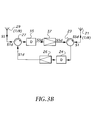
- Fig. 3B is a block diagram showing such a repeater.
- an antenna 21 is for the base station, and an antenna 29 is for mobile stations.
- Each of the antennas 21 and 29 is a transmitting-receiving antenna.
- a wave S1 received by the antenna 21 for the base station is supplied to a delay circuit 24 through a circulator 23.
- the delay circuit 24 provides the signal S1 with a delay of one chip interval or more, and supplies the delayed signal to an amplifier 26.
- the amplifier 26 amplifies the delayed signal S1 d, and feeds it through a circulator 27 to the antenna 29 which radiates it to mobile stations.
- a wave S5 received by the antenna 29 for mobile stations is supplied to a delay circuit 35 through a circulator 27.
- the delay circuit 35 provides the signal S5 with a delay of one chip interval or more, and supplies it to an amplifier 37.
- the amplifier 37 amplifies the delayed signal S5d, and feeds it through the circulator 23 to the antenna 21 which radiates it to the base station.
- the repeater of this embodiment is used in areas other than dead zones. For example, it is used in such areas as voice signal communications can be sufficiently achieved, but improvement in bit error rates of data signals is required.
- a mobile station receives a wave directly transmitted from the base station, and the delayed wave radiated from the antenna 29 of the repeater, and carries out the secondary demodulation, the RAKE reception, and the primary demodulation, thereby obtaining the desired data from the base station.
- the base station receives a wave directly transmitted from the mobile station, and the delayed wave radiated from the antenna 21, and performs the secondary demodulation, the RAKE reception, and the primary demodulation, thereby obtaining the data from the mobile station. This makes it possible to reduce the bit error rate of the data transmission. It is obvious that the repeaters of the first and second embodiments can also be used in such places.
- the base station In mobile communications, there are substantial differences among the received levels of electric waves transmitted from individual mobile stations to the base station. This is due to large distance differences between the mobile stations and the base station, multipaths formed by reflection from buildings, or the like. Accordingly, the base station must control the transmission power level of mobile stations in such a manner that the received levels from the mobile stations meet a reference level.
- the repeater in accordance with the present invention When the repeater in accordance with the present invention is used, the signal received via the repeater and the signal received directly are automatically combined by the RAKE reception. This has an advantage that the installation of repeaters can be achieved transparently to the base station and mobile stations.
- Fig. 4 is a block diagram showing an embodiment of a spread-spectrum communication receiver in accordance with the present invention.
- the receiver adopts the RAKE receiving method as a conventional receiver as shown in Fig. 1, it differs in the following points:
- each weighting coefficient control circuit 40-k determines the weighting coefficient by comparing the symbol decision result with the output of the corresponding detector, and by detecting a desired signal component contained in the output of the detector, as will be described later.
- weighting by the desired signal components or weighting in accordance with SIR is used.
- the signals thus weighted by the weighting coefficients are combined by a combining circuit 5, and the combined signal undergoes symbol decision by the symbol decision circuit 6.
- Fig. 5 is a circuit diagram showing a more specific arrangement from the detector 42 to the symbol decision circuit 6 of Fig. 4.
- reference numeral 43 (43-1 - 43-N) designates a circuit incorporating the detector 42 and the weighting coefficient control circuit 40.
- Each element 43- k includes a substracter 51, multipliers 52 and 53, and a calculation circuit 54.
- the calculation circuit 54 includes a memory circuit storing adaptive algorithm and a calculation circuit.
- the received signal can be represented as Z, x ei".
- the transfer function Z represents the phase shift and fluctuations of the amplitude due to fading.
- the transfer function Z, of the propagation path is estimated by the adaptive algorithm, and the estimated value Z k is obtained.
- the ratio of the detected output of a delayed wave to the symbol decision result increases with an increase of the desired wave component in the delayed wave.
- the estimated value Z k represents the ratio of the detected output of each delayed wave to the symbol decision result, which indicates the magnitude of the desired wave component contained in the delayed wave. Therefore, using the estimated value Z k makes it possible to measure SNR and SIR for each delayed wave. Since the present invention performs weighting using the estimated value Z k , more appropriate weighting can be achieved than the conventional weighting using the output power of the detector, thereby improving the characteristics of the RAKE reception.
- the embodiment employs the delay detection or synchronous detection, and hence, the first received information symbol cannot be decoded because of phase uncertainty.
- the delay detection since a preamble which is a known information symbol is normally sent, the preamble symbols may be fed back to the detector 42 as the decision results.
- the synchronous detection a known pilot signal can be used which is inserted to obtain the absolute phase of the received signal, and whose length is one symbol interval or more. Thus, the decision results of the symbols of the pilot signal is fed back to the detector 42.
- this embodiment carries out weighting by the power of the estimated desired wave by providing the weighting circuit 3-i with the square
- combining the receiver with the repeater in accordance with the present invention makes it possible to achieve high quality communications between a base station and a mobile station in a dead zone.
Abstract
Description
- The present invention relates to a receiver and a repeater for spread-spectrum communications which improve diversity characteristics.
- Generally, the spread-spectrum communications such as CDMA (Code Division Multiple Access) performs a plurality of modulations at a transmitting side, and corresponding demodulations at a receiving side, thereby communicating information symbols. More specifically, the transmitting side transmits information symbols after performing a primary modulation, such as PSK, of the information symbols, and then, spreading the primary modulation signal into a wideband frequency range by performing a secondary modulation using a spreading code such as a high-rate pseudo-random code. On the other hand, the receiving side performs despreading (secondary demodulation) using the same and synchronized spreading code with the transmitting side so that the wideband frequency received signal is inversely converted into the band of the information symbols, and then, carries out a primary demodulation corresponding to the primary modulation, thereby restoring the original information symbols.
- When such a spread-spectrum communication method is employed in mobile communications, a signal transmitted from a base station or a mobile station will reflect from obstacles such as buildings or the like on its propagation paths. Accordingly, the signal is received as a multipath signal whose component waves (delayed waves) arrive at different times because individual delayed waves have different delay times on the propagation paths. If the variance of the delay times of the propagation paths is greater than one element length of a spreading code (one chip interval), fluctuations of the individual delayed wave components which are extracted at every chip interval can be handled as non-correlated quantity. In other words, the amplitude and phase of each delayed wave component can be considered to change independently. As a result, the average received level will be improved by combining the independent delayed wave components after making their phases coherent, or by selecting a delayed wave component whose amplitude is maximum. This idea is implemented as a well-known RAKE reception, wherein improvement in transmission characteristics can be expected owing to the path diversity receiving effect.
- Fig. 1 is a block diagram showing a conventional spread-spectrum communication receiver carrying out the path diversity reception (RAKE reception). In Fig. 1, the reference numerals 1-1 - 1-N designate correlators. Each correlator 1-k (k = 1 - N) receives a spread-
spectrum signal 100, into which a pilot signal is inserted, and performs despreading of one of delayed waves using the same spreading code. Here, the pilot signal is a signal (called a sounder) measuring a transfer function of a propagation path. The output of the correlator 1-k is supplied to a detector 2-k which detects one of the delayed waves. The output of the detector 2-k is supplied to a weighting circuit 3-k and a power detector 4-k. The power detector 4-k detects power of the delayed wave, and makes it a coefficient of the weighting circuit 3-k. Respective weighted signals are combined by a combiningcircuit 5. The combined signal is sent to asymbol decision circuit 6 which decides the symbol. When the weighting is performed using all the outputs of the power detectors 4-k, a maximal ratio combining is achieved, whereas when the detected signal of the maximum power is selected, a selection combining is achieved - The conventional spread-spectrum communication system has the following drawbacks.
- (1) In the above-mentioned arrangement which detects the respective delayed waves independently, the operation of the detectors will become unstable if the signal-to-noise power ratio (SNR) or the signal-to-interference power ratio (SIR) of the delayed waves is small.
- (2) In the spread-spectrum communications, since the SIR changes greatly for individual information symbols, it is difficult to achieve an optimum combination even if weighting based on the received power is performed. Accordingly, only insufficient diversity effect can be obtained.
- (3) A cellular mobile communication system covers a wide service area by locating a plurality radio base stations. In the service area, however, there are some areas as in tunnels where received signal strength is weak and communication quality becomes low. It is impossible to communicate in such places. Although it may possible to provide these dead zones with new base stations, this is not economical because equipment and scale of a base station are large.
- (4) Although differences between delay times of propagation paths must be greater than one chip interval to divide a multipath wave into delayed waves, these differences are not always obtained in all areas. For example, assuming that the bandwidth of the primary modulation is 16 kHz, and the bandwidth of the second modulation using a spreading code is 128 times greater than that, that is 2048 kHz, the resolving power of the delay is about 0.5 micro-seconds. Accordingly, the multipath wave cannot be divided into individual delayed waves when the delay time differences of the propagation paths are less than this value. As a result, fading will occur as in TDMA, and one of the distinctive features of the CDMA are lost.
- Therefore, an object of the present invention is to provide a repeater for a spread-spectrum mobile communication system, which can improve the communication quality in dead zones and other areas while maintaining the distinctive features of the CDMA.
- Another object of the present invention is to provide a receiver for a spread-spectrum mobile communication system, which can achieve stable detecting characteristics and optimum weighting of individual delayed wave components.
- In a first aspect of the present invention, there is provided a repeater for repeating transmitted and received signals between a mobile station and a base station of a mobile communication system which performs spread spectrum communications, the repeater comprising:
- a first receiving antenna for receiving an electric wave from the base station;
- a first delay circuit for providing a received signal supplied from the first receiving antenna with a predetermined amount of delay;
- a first transmitting antenna for radiating an output of the first delay circuit to the mobile station;
- a second receiving antenna for receiving an electric wave from the mobile station;
- a second delay circuit for providing a received signal supplied from the second receiving antenna with a predetermined amount of delay; and
- a second transmitting antenna for radiating an output of the second delay circuit to the base station,
- wherein a delay time of the first delay circuit and a delay time of the second delay circuit are set at one chip interval of a spreading code or more.
- Here, the repeater may further comprise:
- a first amplifier for amplifying the output of the first delay circuit, and for feeding it to the first transmitting antenna; and
- a second amplifier for amplifying the output of the second delay circuit, and for feeding it to the second transmitting antenna.
- The first receiving antenna and the second transmitting antenna may consist of one antenna, and this antenna is connected to an input terminal of the first delay circuit and an output terminal of the second amplifier via a first circulator which separates a received signal and a transmitted signal, and the second receiving antenna and the first transmitting antenna consist of one antenna, and this antenna is connected to an input terminal of the second delay circuit and an output terminal of the first amplifier via a second circulator which separates a received signal and a transmitted signal.
- The repeater may further comprise:
- a third receiving antenna for receiving an electric wave from the base station;
- first combining means for combining a received signal fed from the third receiving antenna with the output of the first delay circuit, and for supplying a combined signal to the first amplifier;
- a fourth receiving antenna for receiving an electric wave from the mobile station; and
- second combining means for combining a received signal fed from the fourth receiving antenna with the output of the second delay circuit, and for supplying a combined signal to the second amplifier.
- The repeater may further comprise:
- a first amplifier for amplifying a received signal fed from the first receiving antenna, and for supplying an amplified signal to the first delay circuit; and
- a second amplifier for amplifying a received signal fed from the second receiving antenna, and for supplying an amplified signal to the second delay circuit.
- The first receiving antenna and the second transmitting antenna may consist of one antenna, and this antenna may be connected to an output terminal of the second delay circuit and an input terminal of the first amplifier via a first circulator which separates a received signal and a transmitted signal, and the second receiving antenna and the first transmitting antenna may consist of one antenna, and this antenna may be connected to an output terminal of the first delay circuit and an input terminal of the second amplifier via a second circulator which separates a received signal and a transmitted signal.
- The repeater may further comprise:
- a third transmitting antenna for radiating an output of the first amplifier to the mobile station; and
- a fourth transmitting antenna for radiating an output of the second amplifier to the base station.
- In a second aspect of the present invention, there is provided a spread-spectrum communication receiver comprising:
- a plurality of correlators for despreading individual delayed waves contained in a received spread-spectrum signal by using an identical spreading code;
- a plurality of detectors, each detects one of delayed wave components outputted from the correlators;
- a plurality of weighting circuits, each multiplies an output of one of the detectors by a weighting coefficient;
- a combining circuit for combining outputs of the weighting circuits;
- a symbol decision circuit for making symbol decision of an output of the combining circuit;
- estimation means for estimating a transfer function of a propagation path associated with each of the delayed wave components on the basis of an output of the symbol decision circuit and outputs of the correlators; and
- a weighting coefficient control circuit for estimating an amplitude of a desired wave component of each of the delayed wave components on the basis of each of the transfer functions estimated, and for generating the weighting coefficients based on the amplitudes.
- Here, the estimation means may comprise:
- a plurality of multipliers, each of which multiplies the output of the symbol decision circuit by one of the transfer functions estimated;
- a plurality of subtracters for obtaining differences between the outputs of the correlators and outputs of the multipliers, respectively, and for producing the differences as estimated errors; and
- a calculation circuit for performing adaptive algorithm recursively estimating the transfer functions from the output of the symbol decision circuit and the estimated errors outputted from the subtracters.
- The weighting coefficient control circuit may obtain a square of an absolute value of each of the transfer functions estimated, and make the square the weighting coefficient associated with each one of the delayed wave components.
- The weighting coefficient control circuit may determine the weighting coefficients on the basis of a ratio between an amplitude of the desired wave component of each of the delayed wave components and corresponding one of the estimated errors.
- In a third aspect of the present invention, there is provided a spread-spectrum communication system having a repeater and a spread-spectrum communication receiver, the repeater repeating transmitted and received signals between a mobile station and a base station of a mobile communication system performing spread-spectrum communications, and the spread-spectrum communication receiver being provided in the mobile station and the base station to receive transmitted signal from the repeater,
- the repeater comprising:
- a first receiving antenna for receiving an electric wave from the base station;
- a first delay circuit for providing a received signal supplied from the first receiving antenna with a predetermined amount of delay;
- a first transmitting antenna for radiating an output of the first delay circuit to the mobile station;
- a second receiving antenna for receiving an electric wave from the mobile station;
- a second delay circuit for providing a received signal supplied from the second receiving antenna with a predetermined amount of delay; and
- a second transmitting antenna for radiating an output of the second delay circuit to the base station,
- wherein a delay time of the first delay circuit and a delay time of the second delay circuit are set at one chip interval of a spreading code or more,
- and the spread spectrum communication receiver comprising:
- a plurality of correlators for despreading individual delayed waves contained in a received spread-spectrum signal by using an identical spreading code;
- a plurality of detectors, each detects one of delayed wave components outputted from the correlators;
- a plurality of weighting circuits, each multiplies an output of one of the detectors by a weighting coefficient;
- a combining circuit for combining outputs of the weighting circuits;
- a symbol decision circuit for making symbol decision of an output of the combining circuit;
- estimation means for estimating a transfer function of a propagation path associated with each of the delayed wave components on the basis of an output of the symbol decision circuit and outputs of the correlators; and
- a weighting coefficient control circuit for estimating an amplitude of a desired wave component of each of the delayed wave components on the basis of each of the transfer functions estimated, and for generating the weighting coefficients based on the amplitudes.
- According to the present invention, a delay difference greater than one chip interval is forcedly provided to a signal transmitted from the repeater. This makes it possible to produce good RAKE receiving effect, eliminate dead zones, and improve transmission quality in the area.
- Moreover, the receiver for the spread-spectrum communication, which performs the diversity combining (RAKE reception), carries out detection and weighting using the results of symbol decision of a signal obtained by the diversity combining. That is, the detection and weighting are carried out based on desired power or SIR estimated using the results of the symbol decision. Consequently, the receiver in accordance with the present invention can obtain more stable detection results than the conventional technique which performs weighting on the basis of the received power, that is, the sum of the desired wave and interference waves.
-
- Fig. 1 is a block diagram showing an example of a conventional spread-spectrum communication receiver which performs path-diversity (RAKE) reception;
- Fig. 2 is a block diagram showing an embodiment of a spread-spectrum communication repeater in accordance with the present invention;
- Figs. 3A and 3B are block diagrams showing other embodiments of a spread-spectrum communication repeater in accordance with the present invention;
- Fig. 4 is a block diagram showing an embodiment of a spread-spectrum communication receiver adopting the RAKE receiving system in accordance with the present invention; and
- Fig. 5 is a block diagram showing a concrete arrangement from a detector to a symbol decision circuit of the embodiment of Fig. 4.
- Embodiments of the invention will now be described with reference to the accompanying drawings.
- Fig. 2 is a block diagram showing an embodiment of a mobile communication system in accordance with the present invention.
- In this figure, a
base station 10 covers an area (radio zone) 9, and is carrying out CDMA communications withmobile stations area 9. Thebase station 10 includes a transmitting-receivingantenna 11 and a radio unit 12, and is connected to a switchingoffice 14 viaparallel lines 13. Arepeater 20 in accordance with the present invention is located at a dead zone or a place where the transmission quality should be improved. - The
repeater 20 hasantennas antennas antennas antennas base station 10 at a carrier frequency f2 is received by theantennas antenna 21 is supplied to acombiner 25 through acirculator 23 for separating transmitted and received signals, and adelay circuit 24. Thedelay circuit 24 provides the received wave S1 with a delay of more than the element length (one chip interval) of a spreading code sequence of the spread-spectrum communications, and supplies the delayed signal S1 to thecombiner 25. On the other hand, the received wave S2 by theantenna 22 is directly supplied to thecombiner 25, and is combined with the signal S1 d. The combined signal is amplified by anamplifier 26, and is fed, as a signal S3, to theantenna 28 for mobile stations through acirculator 27 for separating transmitted and received signals, and is transmitted to the mobile stations. Thus, therepeater 20 transmits the signal S3 produced by combining the signal S1 d delayed by thedelay circuit 24 with the signal S2 having no delay. - The electric wave radiated from the
antenna 28 of therepeater 20 is received by a transmitting-receivingantenna 31 of amobile station 16. Theantenna 31 also receives an electric wave radiated from the transmitting-receivingantenna 11 of thebase station 10. Thus, themobile station 16 receives three signals: the delayed signal from therepeater 20; the non-delayed signal from therepeater 20; and the signal directly transmitted from thebase station 10. These signals are supplied to aradio unit 32 of themobile station 16. Theradio unit 32 performs secondary demodulation (despreading) of the signals using an assigned spreading code, and RAKE reception, followed by the primary demodulation, thereby obtaining the data transmitted from thebase station 10 to themobile station 16. - On the other hand, data to be transmitted from the
mobile station 16 is subject to the primary and secondary modulations in theradio unit 32, and is radiated from a transmitting-receivingantenna 31 as an electric wave whose carrier frequency is f1. The electric wave is received byantennas repeater 20 for mobile stations. A wave S5 received by theantenna 28 is supplied to acombiner 36 through acirculator 27 for separating transmitted and received signals, and adelay circuit 35. Thedelay circuit 35 provides the received signal S5 with a delay time more than the length of an element (a chip interval) of the spreading code sequence of the spread-spectrum communication, and supplies a delayed signal S5d to thecombiner 36. On the other hand, a wave S6 received by theantenna 29 is directly supplied to thecombiner 36, and is combined with the signal S5d. A combined signal is amplified by anamplifier 37, fed to theantenna 21 for the base station through thecirculator 23 for separating transmitted and received signals, and is radiated to the base station. Thus, therepeater 20 transmits to the base station 10 a combined signal S7 of the signal S5d delayed by thedelay circuit 35 and the signal S6 including no delay. - An electric wave radiated from the
antenna 21 of therepeater 20 is received by the transmitting-receivingantenna 11 of thebase station 10. Theantenna 11 receives the electric wave radiated by the transmitting-receivingantenna 31 of themobile station 16, as well. In other words, thebase station 10 receives three signals: the signal delayed by therepeater 20, the signal not delayed by therepeater 20, and the signal directly transmitted from themobile station 16. These signals are supplied to the radio equipment 12 of the base station. The radio equipment 12 performs the secondary demodulation (despreading) by taking correlation between the received signals and an assigned spreading code, and RAKE reception of the despread signal, followed by the primary demodulation, thereby obtaining data transmitted from themobile station 16 to thebase station 10. - Thus, setting the delay times of the
delay circuits - Although the repeater of the first embodiment employs two receiving antennas and one transmitting antenna for each of the base station and the mobile station, it is not restricted to this arrangement. For example, a combination of three or more receiving antennas and one or more transmitting antennas can also be used. The point is to provide the same received signal with a plurality of signal paths from the received antenna to the transmitting antenna, and to provide at least one of the signal paths with a delay time of more than the chip interval of the spreading code.
- Alternatively, one receiving antenna and two transmitting antennas may also be used, which is the reversal of the first embodiment. A second embodiment is a repeater having such a configuration.
- Fig. 3A is a block diagram showing the arrangement of a second embodiment. In Fig. 3A,
antennas antennas antennas antennas antenna 22 is supplied to theantenna 28 through acirculator 23 and anamplifier 26, and is radiated to mobile stations. The signal S1 outputted from theamplifier 26 is delayed by adelay circuit 24. A delayed signal S1 is fed to theantenna 29 through acirculator 27, and is radiated to the mobile stations. Thus, therepeater 20 transmits the delayed signal S1 and the non-delayed signal S1 to the mobile stations. The delay time of thedelay circuit 24 is set at a value greater than one chip interval as in the first embodiment. - On the other hand, a received wave S5 by the
antenna 29 for mobile stations is supplied to theantenna 21 through acirculator 27 and anamplifier 37, and is radiated to the base station. In addition, the received wave S5 outputted from theamplifier 37 is delayed by thedelay circuit 35. The delayed signal S5d is supplied to theantenna 22 through thecirculator 23, and is radiated to thebase station 10. Thus, therepeater 20 transmits the delayed signal S5d and the non-delayed signal S5 to thebase station 10. The delay time of thedelay circuit 35 is set at a value greater than the chip interval as in the first embodiment. - When using the repeaters of the first or second embodiment for dead zones, they are placed at line-of-sight areas from which the dead zones can be unobstructedly viewed. The repeaters receive and amplify waves transmitted from the base station, and transmit them to the dead zones. The repeaters also receive and amplify waves transmitted from mobile stations in the dead zones, and transmit them to the base station. The repeaters include a plurality of signal paths between the receiving antenna and the transmitting antenna, forcedly produce multipath waves using the delay circuits, and transmit them. Accordingly, the multipath waves have time shifts by more than one chip interval and hence, they can be resolved and made phase coherent by the RAKE reception. Thus, the RAKE receiving effect in the mobile stations and the base station makes it possible to achieve high quality communications in the dead zones or in other areas.
- The
repeater 20 generates a pair of signals in the first and second embodiments: a delayed signal and a non-delayed signal. However, considering that there are signals transmitted and received through a direct path between thebase station 10 and themobile station 16 in areas other than dead zones, a receiving side can obtain the pair of signals even if therepeater 20 transmits only a delayed signal. Consequently, such a repeater located at a place other than dead zones can considerably improve the transmission characteristic. - Fig. 3B is a block diagram showing such a repeater. In Fig. 3B, an
antenna 21 is for the base station, and anantenna 29 is for mobile stations. Each of theantennas - A wave S1 received by the
antenna 21 for the base station is supplied to adelay circuit 24 through acirculator 23. Thedelay circuit 24 provides the signal S1 with a delay of one chip interval or more, and supplies the delayed signal to anamplifier 26. Theamplifier 26 amplifies the delayed signal S1 d, and feeds it through acirculator 27 to theantenna 29 which radiates it to mobile stations. - On the other hand, a wave S5 received by the
antenna 29 for mobile stations is supplied to adelay circuit 35 through acirculator 27. Thedelay circuit 35 provides the signal S5 with a delay of one chip interval or more, and supplies it to anamplifier 37. Theamplifier 37 amplifies the delayed signal S5d, and feeds it through thecirculator 23 to theantenna 21 which radiates it to the base station. - The repeater of this embodiment is used in areas other than dead zones. For example, it is used in such areas as voice signal communications can be sufficiently achieved, but improvement in bit error rates of data signals is required.
- In this case, a mobile station receives a wave directly transmitted from the base station, and the delayed wave radiated from the
antenna 29 of the repeater, and carries out the secondary demodulation, the RAKE reception, and the primary demodulation, thereby obtaining the desired data from the base station. On the other hand, the base station receives a wave directly transmitted from the mobile station, and the delayed wave radiated from theantenna 21, and performs the secondary demodulation, the RAKE reception, and the primary demodulation, thereby obtaining the data from the mobile station. This makes it possible to reduce the bit error rate of the data transmission. It is obvious that the repeaters of the first and second embodiments can also be used in such places. - In mobile communications, there are substantial differences among the received levels of electric waves transmitted from individual mobile stations to the base station. This is due to large distance differences between the mobile stations and the base station, multipaths formed by reflection from buildings, or the like. Accordingly, the base station must control the transmission power level of mobile stations in such a manner that the received levels from the mobile stations meet a reference level. When the repeater in accordance with the present invention is used, the signal received via the repeater and the signal received directly are automatically combined by the RAKE reception. This has an advantage that the installation of repeaters can be achieved transparently to the base station and mobile stations.
- Next, a receiver that can achieve a satisfactory RAKE reception in connection with such a repeater will be described.
- Fig. 4 is a block diagram showing an embodiment of a spread-spectrum communication receiver in accordance with the present invention. Although the receiver adopts the RAKE receiving method as a conventional receiver as shown in Fig. 1, it differs in the following points:
- (1) Instead of the detectors 2-k (k = 1 - N), detectors 42-k are employed.
- (2) Instead of the power detectors 4-k, weighting coefficient control circuits 40-k are provided.
- (3) The output of the
symbol decision circuit 6 is fed back to the detectors 42-k and weighting coefficient control circuits 40-k, and is used as a reference of the detection and the weighting. - In the receiver of Fig. 4, delayed waves ik outputted from correlators 1-k are supplied to the detectors 42-k to be detected, respectively. The outputs of the detectors 42-k are supplied to the weighting coefficient control circuits 40-k, which calculate weighting coefficients of delayed wave components, respectively. Specifically, each weighting coefficient control circuit 40-k determines the weighting coefficient by comparing the symbol decision result with the output of the corresponding detector, and by detecting a desired signal component contained in the output of the detector, as will be described later. As a method for determining the weighting coefficients, weighting by the desired signal components, or weighting in accordance with SIR is used. The signals thus weighted by the weighting coefficients are combined by a combining
circuit 5, and the combined signal undergoes symbol decision by thesymbol decision circuit 6. - Fig. 5 is a circuit diagram showing a more specific arrangement from the
detector 42 to thesymbol decision circuit 6 of Fig. 4. In Fig. 5, reference numeral 43 (43-1 - 43-N) designates a circuit incorporating thedetector 42 and the weightingcoefficient control circuit 40. Each element 43- k includes asubstracter 51,multipliers calculation circuit 54. Thecalculation circuit 54 includes a memory circuit storing adaptive algorithm and a calculation circuit. - Assuming that a transmitted signal whose amplitude is 1 is represented as ei", and the transfer function of the propagation path is Z" the received signal can be represented as Z, x ei". The transfer function Z, represents the phase shift and fluctuations of the amplitude due to fading. The purpose of the adaptive algorithm is to obtain such estimated transfer function Zk (k = 1 - N) that makes Zk = Zr. In other words, the purpose is to obtain Zk that will minimize the following estimated error.

- The procedure for estimating the optimum Zk successively on the basis of the decided value fed- back from the
symbol decision circuit 6 and the estimated error ek will now be described. Details of this method is explained, for example, in Simon Haykin, "Adaptive Filter Theory", Prentice Hall, 1986 (ISBN 0-13-004052-5) pp. 381-385. - (1) The
multiplier 52 multiplies the input signal i = Z, x ei" by 1/Zk. The result is ek = (Zr/Zk)ejφ. If the estimation is correct, Z, = Zk holds, and the transmitted signal ejφ is obtained. In practice, however, the estimation includes error because of noise or the like. - (2) The weighting circuit 3-k, receiving the output of the
multiplier 52, performs weighting using the square of the absolute value of the estimated transfer function Zk, that is, |Zk|2, thereby carrying out the maximal ratio combining diversity. - (3) The combining
circuit 5 sums up the outputs ZrZk*ejφ of individual weighting circuits 3-k. Thus, the weighting combination which is a requirement of the maximal ratio combining diversity is achieved. - (4) The
symbol decision circuit 6 decides the symbol produced from the combiningcircuit 5. The result ejφ will be obtained if there is no bit error. - (5) Each
multiplier 53 produces an estimated received signal. Specifically, it multiplies the output of thesymbol decision circuit 6 by the estimated transfer function Zk, and makes the product Zk x ejφ the estimated received signal. - (6) Each
subtracter 51 subtracts the estimated received signal Zk x ejφ from the input signal Z, x ejφ, thereby obtaining the estimated error ek. - (7) The estimated transfer function Zk is updated such that the estimated error ek is further reduced. This is performed using the adaptive algorithm in accordance with the recursive least square method (RLS), though other adaptive algorithm can be employed.
- (8) The same processing is repeated after returning to (1).
- Thus, the transfer function Z, of the propagation path is estimated by the adaptive algorithm, and the estimated value Zk is obtained. The ratio of the detected output of a delayed wave to the symbol decision result increases with an increase of the desired wave component in the delayed wave. The estimated value Zk represents the ratio of the detected output of each delayed wave to the symbol decision result, which indicates the magnitude of the desired wave component contained in the delayed wave. Therefore, using the estimated value Zk makes it possible to measure SNR and SIR for each delayed wave. Since the present invention performs weighting using the estimated value Zk, more appropriate weighting can be achieved than the conventional weighting using the output power of the detector, thereby improving the characteristics of the RAKE reception.
- The embodiment employs the delay detection or synchronous detection, and hence, the first received information symbol cannot be decoded because of phase uncertainty. However, in the delay detection, since a preamble which is a known information symbol is normally sent, the preamble symbols may be fed back to the
detector 42 as the decision results. On the other hand, in the synchronous detection, a known pilot signal can be used which is inserted to obtain the absolute phase of the received signal, and whose length is one symbol interval or more. Thus, the decision results of the symbols of the pilot signal is fed back to thedetector 42. - Although this embodiment carries out weighting by the power of the estimated desired wave by providing the weighting circuit 3-i with the square |Zk|2 of the absolute value of the estimated transfer function Zk from the
calculation circuit 54, the weighting is not restricted to this method. For example, using the value |Zk|2|ek|2 which is obtained by dividing the square |Zk|2 of the absolute value of the estimated transfer function Zk by the square lekl 2 of the absolute value of the estimated error ek enables to weight by SIR. - Furthermore, combining the receiver with the repeater in accordance with the present invention makes it possible to achieve high quality communications between a base station and a mobile station in a dead zone.
Claims (21)
Applications Claiming Priority (5)
| Application Number | Priority Date | Filing Date | Title |
|---|---|---|---|
| JP196023/93 | 1993-08-06 | ||
| JP19602393 | 1993-08-06 | ||
| JP9035194 | 1994-04-27 | ||
| JP90351/94 | 1994-04-27 | ||
| PCT/JP1994/001283 WO1995005037A1 (en) | 1993-08-06 | 1994-08-04 | Receiver and repeater for spread spectrum communication |
Publications (2)
| Publication Number | Publication Date |
|---|---|
| EP0668662A1 true EP0668662A1 (en) | 1995-08-23 |
| EP0668662A4 EP0668662A4 (en) | 1997-02-12 |
Family
ID=26431841
Family Applications (1)
| Application Number | Title | Priority Date | Filing Date |
|---|---|---|---|
| EP94923066A Withdrawn EP0668662A4 (en) | 1993-08-06 | 1994-08-04 | Receiver and repeater for spread spectrum communication. |
Country Status (6)
| Country | Link |
|---|---|
| US (1) | US5652765A (en) |
| EP (1) | EP0668662A4 (en) |
| KR (1) | KR0164250B1 (en) |
| CN (1) | CN1068477C (en) |
| CA (1) | CA2146445C (en) |
| WO (1) | WO1995005037A1 (en) |
Cited By (33)
| Publication number | Priority date | Publication date | Assignee | Title |
|---|---|---|---|---|
| FR2732173A1 (en) * | 1995-03-22 | 1996-09-27 | Nec Corp | Radio communication system for dispersed spectrum signals |
| WO1997002675A2 (en) * | 1995-06-30 | 1997-01-23 | Interdigital Technology Corporation | Cdma modem |
| WO1997008848A1 (en) * | 1995-08-23 | 1997-03-06 | Qualcomm Incorporated | Method and system for non-orthogonal noise energy based gain control |
| WO1997019522A2 (en) * | 1995-11-20 | 1997-05-29 | Nokia Telecommunications Oy | Method for controlling a receiver, and a receiver |
| EP0825727A1 (en) * | 1996-08-23 | 1998-02-25 | Ntt Mobile Communications Network Inc. | Rake receiver |
| WO1998027666A1 (en) * | 1996-12-18 | 1998-06-25 | Alcatel Usa Sourcing L.P. | Multipath equalization using taps derived from a parallel correlator |
| EP0893888A2 (en) * | 1997-07-25 | 1999-01-27 | Kabushiki Kaisha Toshiba | Spread spectrum communication apparatus and rake receiver |
| US5935405A (en) * | 1996-09-12 | 1999-08-10 | Bayer Aktiengesellschaft | Process for producing rigid and flexible circuits |
| WO1999044308A1 (en) * | 1998-02-24 | 1999-09-02 | Repeater Technologies, Inc. | Delay combiner system for cdma repeaters and low noise amplifiers |
| EP0982871A2 (en) * | 1998-08-24 | 2000-03-01 | Nec Corporation | CDMA Rake reception signal combining |
| EP0987828A2 (en) * | 1998-09-14 | 2000-03-22 | Nec Corporation | Spread spectrum rake receiver |
| US6049535A (en) * | 1996-06-27 | 2000-04-11 | Interdigital Technology Corporation | Code division multiple access (CDMA) communication system |
| US6192249B1 (en) | 1998-12-03 | 2001-02-20 | Qualcomm Inc. | Method and apparatus for reverse link loading estimation |
| EP1189362A1 (en) * | 2000-03-28 | 2002-03-20 | Matsushita Electric Industrial Co., Ltd. | Communication apparatus and communication method |
| US6397070B1 (en) | 1999-07-21 | 2002-05-28 | Qualcomm Incorporated | Method and apparatus for estimating reverse link loading in a wireless communication system |
| USRE37820E1 (en) | 1994-06-28 | 2002-08-13 | Littlefeet, Inc. | Arrangements of base transceiver stations of an area-covering network |
| US6442398B1 (en) | 1998-12-03 | 2002-08-27 | Qualcomm Incorporated | Method and apparatus for reverse link loading estimation |
| WO2002093770A1 (en) * | 2001-05-17 | 2002-11-21 | Qualcomm Incorporated | System and method for adjusting combiner weights using an adaptive algorithm in a wireless communications system |
| KR100419789B1 (en) * | 2001-08-10 | 2004-02-21 | 주식회사 텔레매틱스 | Apparatus for Interexchanging Multi-Path of Mobile Communication System using Delay Process |
| US6801516B1 (en) | 1995-06-30 | 2004-10-05 | Interdigital Technology Corporation | Spread-spectrum system for assigning information signals having different data rates |
| FR2854995A1 (en) * | 2003-05-14 | 2004-11-19 | Nortel Networks Ltd | Code division multiple access (CDMA) modulator/demodulator having spread spectrum combiners summing mutual contributions less than symbol length separation following input sequences/converting radio transmitter spread spectrum |
| US6885652B1 (en) | 1995-06-30 | 2005-04-26 | Interdigital Technology Corporation | Code division multiple access (CDMA) communication system |
| EP1003297A3 (en) * | 1998-11-10 | 2005-09-21 | Lucent Technologies Inc. | Transmit diversity and reception equalization for radio links |
| WO2006028352A1 (en) * | 2004-09-10 | 2006-03-16 | Samsung Electronics Co., Ltd. | A method and system for of creating active multipaths for mimo wireless systems |
| US7433384B2 (en) | 2001-05-17 | 2008-10-07 | Qualcomm Incorporated | System and method for received signal prediction in wireless communications system |
| WO2008150534A2 (en) * | 2007-06-01 | 2008-12-11 | Nextivity, Inc. | Short range booster and methods for boosting with multiple antennas |
| US8442572B2 (en) | 2006-09-08 | 2013-05-14 | Qualcomm Incorporated | Method and apparatus for adjustments for delta-based power control in wireless communication systems |
| US8452316B2 (en) | 2004-06-18 | 2013-05-28 | Qualcomm Incorporated | Power control for a wireless communication system utilizing orthogonal multiplexing |
| US8488487B2 (en) | 2006-09-08 | 2013-07-16 | Qualcomm Incorporated | Method and apparatus for fast other sector interference (OSI) adjustment |
| US8516314B2 (en) | 2004-06-18 | 2013-08-20 | Qualcomm Incorporated | Robust erasure detection and erasure-rate-based closed loop power control |
| US8849210B2 (en) | 2005-03-15 | 2014-09-30 | Qualcomm Incorporated | Interference control in a wireless communication system |
| US8848574B2 (en) | 2005-03-15 | 2014-09-30 | Qualcomm Incorporated | Interference control in a wireless communication system |
| US8929908B2 (en) | 2005-10-27 | 2015-01-06 | Qualcomm Incorporated | Method and apparatus for estimating reverse link loading in a wireless communication system |
Families Citing this family (57)
| Publication number | Priority date | Publication date | Assignee | Title |
|---|---|---|---|---|
| FI97583C (en) * | 1995-02-02 | 1997-01-10 | Nokia Mobile Phones Ltd | Procedure for data communication, transmitters and receivers |
| US6788662B2 (en) | 1995-06-30 | 2004-09-07 | Interdigital Technology Corporation | Method for adaptive reverse power control for spread-spectrum communications |
| US6697350B2 (en) | 1995-06-30 | 2004-02-24 | Interdigital Technology Corporation | Adaptive vector correlator for spread-spectrum communications |
| US7929498B2 (en) | 1995-06-30 | 2011-04-19 | Interdigital Technology Corporation | Adaptive forward power control and adaptive reverse power control for spread-spectrum communications |
| US6816473B2 (en) | 1995-06-30 | 2004-11-09 | Interdigital Technology Corporation | Method for adaptive forward power control for spread-spectrum communications |
| US7020111B2 (en) | 1996-06-27 | 2006-03-28 | Interdigital Technology Corporation | System for using rapid acquisition spreading codes for spread-spectrum communications |
| US6108364A (en) * | 1995-08-31 | 2000-08-22 | Qualcomm Incorporated | Time division duplex repeater for use in a CDMA system |
| JPH09116475A (en) * | 1995-10-23 | 1997-05-02 | Nec Corp | Time diversity transmission/reception system |
| JP3165447B2 (en) * | 1995-11-29 | 2001-05-14 | 株式会社エヌ・ティ・ティ・ドコモ | Diversity receiving device and control method |
| US6223019B1 (en) | 1996-03-14 | 2001-04-24 | Sirius Satellite Radio Inc. | Efficient high latitude service area satellite mobile broadcasting systems |
| CA2210582C (en) * | 1996-07-24 | 2001-01-30 | Ntt Mobile Communications Network Inc. | Method and apparatus for receiving cdma radio communication |
| US5864579A (en) * | 1996-07-25 | 1999-01-26 | Cd Radio Inc. | Digital radio satellite and terrestrial ubiquitous broadcasting system using spread spectrum modulation |
| US6633743B1 (en) * | 1996-12-24 | 2003-10-14 | Lucent Technologies Inc. | Remote wireless communication device |
| US6023616A (en) * | 1998-03-10 | 2000-02-08 | Cd Radio Inc. | Satellite broadcast receiver system |
| US6275484B1 (en) * | 1997-06-23 | 2001-08-14 | Lucent Technologies Inc. | Methods and apparatus for increasing the uplink gain for a CDMA base station |
| US6061548A (en) * | 1997-07-17 | 2000-05-09 | Metawave Communications Corporation | TDMA repeater eliminating feedback |
| KR100242132B1 (en) * | 1997-08-22 | 2000-02-01 | 윤종용 | Apparatus for delaying an imformation signal for transmission correspond to sector respectively and transmitting the deayed signal in a base station of mobile communicatim system |
| DE19741872C1 (en) | 1997-09-23 | 1999-02-04 | Deutsche Telekom Ag | Adaptive receiver for CDMA base station |
| US20020051434A1 (en) * | 1997-10-23 | 2002-05-02 | Ozluturk Fatih M. | Method for using rapid acquisition spreading codes for spread-spectrum communications |
| US6507741B1 (en) * | 1997-12-17 | 2003-01-14 | Nortel Networks Limited | RF Repeater with delay to improve hard handoff performance |
| JP2918873B1 (en) | 1998-02-17 | 1999-07-12 | 株式会社エイ・ティ・アール環境適応通信研究所 | Array antenna device for spread spectrum communication |
| US6366607B1 (en) | 1998-05-14 | 2002-04-02 | Interdigital Technology Corporation | Processing for improved performance and reduced pilot |
| JP2982795B1 (en) * | 1998-06-29 | 1999-11-29 | 日本電気株式会社 | Spread spectrum signal receiving method and receiver |
| JP3028804B2 (en) * | 1998-07-03 | 2000-04-04 | 日本電気株式会社 | CDMA receiving method and receiving circuit |
| US6658050B1 (en) * | 1998-09-11 | 2003-12-02 | Ericsson Inc. | Channel estimates in a CDMA system using power control bits |
| FI106897B (en) | 1998-09-14 | 2001-04-30 | Nokia Networks Oy | RAKE receiver |
| US6314127B1 (en) | 1999-02-23 | 2001-11-06 | Lucent Technologies Inc. | System and method for enhancing signal reception |
| SE514436C2 (en) * | 1999-06-18 | 2001-02-26 | Ericsson Telefon Ab L M | Arrangements in a radio system |
| ES2264586T3 (en) * | 1999-11-26 | 2007-01-01 | Nokia Corporation | RAKE RECEIVER. |
| JP3732707B2 (en) * | 2000-03-16 | 2006-01-11 | 富士通株式会社 | Resynchronization control device and resynchronization method in subscriber side communication device |
| WO2002011301A2 (en) * | 2000-08-01 | 2002-02-07 | Repeater Technologies, Inc. | Improved delay combiner system for cdma repeaters and low noise amplifiers |
| US7016332B2 (en) * | 2000-12-05 | 2006-03-21 | Science Applications International Corporation | Method and system for a remote downlink transmitter for increasing the capacity of a multiple access interference limited spread-spectrum wireless network |
| US7061891B1 (en) | 2001-02-02 | 2006-06-13 | Science Applications International Corporation | Method and system for a remote downlink transmitter for increasing the capacity and downlink capability of a multiple access interference limited spread-spectrum wireless network |
| US7209515B2 (en) | 2001-03-30 | 2007-04-24 | Science Applications International Corporation | Multistage reception of code division multiple access transmissions |
| US7006461B2 (en) * | 2001-09-17 | 2006-02-28 | Science Applications International Corporation | Method and system for a channel selective repeater with capacity enhancement in a spread-spectrum wireless network |
| US8498234B2 (en) | 2002-06-21 | 2013-07-30 | Qualcomm Incorporated | Wireless local area network repeater |
| FR2845217B1 (en) * | 2002-09-27 | 2004-12-17 | St Microelectronics Sa | PROCESS FOR PROCESSING AN INCIDENT SIGNAL WITHIN A MULTI-FINGER "RAKE" RECEIVER AND CORRESPONDING "RAKE" RECEIVER |
| US8885688B2 (en) | 2002-10-01 | 2014-11-11 | Qualcomm Incorporated | Control message management in physical layer repeater |
| WO2004045117A1 (en) * | 2002-11-12 | 2004-05-27 | Zyray Wireless, Inc. | Method and apparatus for rake combining based upon signal to interference noise ratio |
| CN1521967A (en) * | 2003-02-11 | 2004-08-18 | 北京三星通信技术研究有限公司 | Method of end-to-end direct communication synchronization in TDM mobile communication system |
| WO2004086730A2 (en) * | 2003-03-26 | 2004-10-07 | Celletra Ltd. | Phase sweeping methods for transmit diversity and diversity combining in bts sector extension and in wireless repeaters |
| WO2006030988A1 (en) * | 2004-09-17 | 2006-03-23 | Matsushita Electric Industrial Co., Ltd. | Wireless transmission system and wireless transmission method and wireless station and transmitting station for use therein |
| US7257040B2 (en) * | 2005-09-27 | 2007-08-14 | Macronix International Co., Ltd. | Fast pre-charge circuit and method of providing same for memory devices |
| WO2007102684A1 (en) * | 2006-03-06 | 2007-09-13 | Airpoint Co., Ltd. | Appararus and method for cancellating interference signal of mobile communication repeater |
| EP1876728B1 (en) | 2006-07-07 | 2014-01-01 | E-Blink | Synchronisation method for two electronic devices over a wireless connection, in particular over a mobile telephone network, as well as a system to implement said procedure |
| EP1895681A1 (en) * | 2006-09-04 | 2008-03-05 | E-Blink | System for wireless transmission of data from a base station to a relay station in a cellular telephone network |
| US20080063046A1 (en) * | 2006-09-12 | 2008-03-13 | Johannes Hendrik Conroy | Method and System for Estimating Signal Error in a Communication System |
| JP5199261B2 (en) | 2006-09-21 | 2013-05-15 | クゥアルコム・インコーポレイテッド | Method and apparatus for mitigating vibration between repeaters |
| DE102006050179A1 (en) * | 2006-10-25 | 2008-05-29 | Alcatel Lucent | Apparatus and method for emulating a reusable environment in a radio network arranged or expanding in an environment free of reusable effects |
| CA2667470A1 (en) * | 2006-10-26 | 2008-05-15 | Qualcomm Incorporated | Repeater techniques for multiple input multiple output utilizing beam formers |
| CN101884243B (en) * | 2007-11-21 | 2013-04-17 | 朗讯科技公司 | CDMA base station and signal processing method used therein |
| US8369268B2 (en) * | 2009-11-06 | 2013-02-05 | Clearwire Ip Holdings Llc | Multiple device to one-antenna combining circuit and methods of using same |
| FR2956934B1 (en) | 2010-02-26 | 2012-09-28 | Blink E | METHOD AND DEVICE FOR TRANSMITTING / RECEIVING ELECTROMAGNETIC SIGNALS RECEIVED / EMITTED ON ONE OR MORE FIRST FREQUENCY BANDS. |
| US20130183895A1 (en) * | 2012-01-13 | 2013-07-18 | Qualcomm Incorporated | System, apparatus, and method for facilitating multi-antenna diversity for repeaters in wireless communication systems |
| FR2990315B1 (en) | 2012-05-04 | 2014-06-13 | Blink E | METHOD FOR TRANSMITTING INFORMATION BETWEEN A TRANSMITTING UNIT AND A RECEIVING UNIT |
| US9031117B2 (en) * | 2012-12-06 | 2015-05-12 | Qualcomm Incorporated | Methods and apparatus for handling fingers with large delay spread through utility optimization |
| CN105746564B (en) * | 2015-12-28 | 2018-07-06 | 山东潍坊润丰化工股份有限公司 | A kind of Pesticidal combination containing imidacloprid and dimehypo and its preparation method and application |
Citations (5)
| Publication number | Priority date | Publication date | Assignee | Title |
|---|---|---|---|---|
| US4291410A (en) * | 1979-10-24 | 1981-09-22 | Rockwell International Corporation | Multipath diversity spread spectrum receiver |
| US4550414A (en) * | 1983-04-12 | 1985-10-29 | Charles Stark Draper Laboratory, Inc. | Spread spectrum adaptive code tracker |
| GB2237706A (en) * | 1989-11-03 | 1991-05-08 | Racal Res Ltd | Radio communications link with diversity |
| US5224122A (en) * | 1992-06-29 | 1993-06-29 | Motorola, Inc. | Method and apparatus for canceling spread-spectrum noise |
| US5233626A (en) * | 1992-05-11 | 1993-08-03 | Space Systems/Loral Inc. | Repeater diversity spread spectrum communication system |
Family Cites Families (3)
| Publication number | Priority date | Publication date | Assignee | Title |
|---|---|---|---|---|
| JPS5850061B2 (en) * | 1978-08-10 | 1983-11-08 | 三菱電機株式会社 | communication facilities |
| US4761796A (en) * | 1985-01-24 | 1988-08-02 | Itt Defense Communications | High frequency spread spectrum communication system terminal |
| JPH05268128A (en) * | 1992-03-18 | 1993-10-15 | Kokusai Denshin Denwa Co Ltd <Kdd> | Cdma communication system |
-
1994
- 1994-08-04 EP EP94923066A patent/EP0668662A4/en not_active Withdrawn
- 1994-08-04 US US08/411,645 patent/US5652765A/en not_active Expired - Fee Related
- 1994-08-04 CN CN94190579A patent/CN1068477C/en not_active Expired - Fee Related
- 1994-08-04 KR KR1019950701308A patent/KR0164250B1/en not_active IP Right Cessation
- 1994-08-04 CA CA002146445A patent/CA2146445C/en not_active Expired - Fee Related
- 1994-08-04 WO PCT/JP1994/001283 patent/WO1995005037A1/en not_active Application Discontinuation
Patent Citations (5)
| Publication number | Priority date | Publication date | Assignee | Title |
|---|---|---|---|---|
| US4291410A (en) * | 1979-10-24 | 1981-09-22 | Rockwell International Corporation | Multipath diversity spread spectrum receiver |
| US4550414A (en) * | 1983-04-12 | 1985-10-29 | Charles Stark Draper Laboratory, Inc. | Spread spectrum adaptive code tracker |
| GB2237706A (en) * | 1989-11-03 | 1991-05-08 | Racal Res Ltd | Radio communications link with diversity |
| US5233626A (en) * | 1992-05-11 | 1993-08-03 | Space Systems/Loral Inc. | Repeater diversity spread spectrum communication system |
| US5224122A (en) * | 1992-06-29 | 1993-06-29 | Motorola, Inc. | Method and apparatus for canceling spread-spectrum noise |
Non-Patent Citations (1)
| Title |
|---|
| See also references of WO9505037A1 * |
Cited By (76)
| Publication number | Priority date | Publication date | Assignee | Title |
|---|---|---|---|---|
| USRE37820E1 (en) | 1994-06-28 | 2002-08-13 | Littlefeet, Inc. | Arrangements of base transceiver stations of an area-covering network |
| US6459900B1 (en) | 1994-06-28 | 2002-10-01 | Littlefeet, Inc. | Methods of operating arrangements of base transceiver stations in an area-covering network |
| FR2732173A1 (en) * | 1995-03-22 | 1996-09-27 | Nec Corp | Radio communication system for dispersed spectrum signals |
| US5912919A (en) * | 1995-06-30 | 1999-06-15 | Interdigital Technology Corporation | Efficient multipath centroid tracking circuit for a code division multiple access (CDMA) system |
| US5991332A (en) * | 1995-06-30 | 1999-11-23 | Interdigital Technology Corporation | Adaptive matched filter and vector correlator for a code division multiple access (CDMA) modem |
| US7756190B2 (en) | 1995-06-30 | 2010-07-13 | Interdigital Technology Corporation | Transferring voice and non-voice data |
| US6212174B1 (en) | 1995-06-30 | 2001-04-03 | Interdigital Technology Corporation | Capacity management method for a code division multiple access (CDM) communication system |
| US6272168B1 (en) | 1995-06-30 | 2001-08-07 | Interdigital Technology Corporation | Code sequence generator in a CDMA modem |
| EP0986187B1 (en) * | 1995-06-30 | 2005-01-26 | Interdigital Technology Corporation | A pilot vector correlator apparatus for a CDMA modem |
| US5796776A (en) * | 1995-06-30 | 1998-08-18 | Interdigital Technology Corporation | Code sequence generator in a CDMA modem |
| US5799010A (en) * | 1995-06-30 | 1998-08-25 | Interdigital Technology Corporation | Code division multiple access (CDMA) communication system |
| US6215778B1 (en) | 1995-06-30 | 2001-04-10 | Interdigital Technology Corporation | Bearer channel modification system for a code division multiple access (CDMA) communication system |
| US6831905B1 (en) | 1995-06-30 | 2004-12-14 | Interdigital Technology Corporation | Spread spectrum system assigning information signals to message-code signals |
| EP0986187A2 (en) * | 1995-06-30 | 2000-03-15 | Interdigital Technology Corporation | A pilot vector correlator apparatus for a CDMA modem |
| US6744809B2 (en) | 1995-06-30 | 2004-06-01 | Interdigital Technology Corporation | Efficient multipath centroid tracking circuit for a code division multiple access (CDMA) system |
| US6801516B1 (en) | 1995-06-30 | 2004-10-05 | Interdigital Technology Corporation | Spread-spectrum system for assigning information signals having different data rates |
| US6381264B1 (en) * | 1995-06-30 | 2002-04-30 | Interdigital Technology Corporation | Efficient multipath centroid tracking circuit for a code division multiple access (CDMA) system |
| WO1997002675A2 (en) * | 1995-06-30 | 1997-01-23 | Interdigital Technology Corporation | Cdma modem |
| WO1997002675A3 (en) * | 1995-06-30 | 1997-04-03 | Interdigital Tech Corp | Cdma modem |
| US6885652B1 (en) | 1995-06-30 | 2005-04-26 | Interdigital Technology Corporation | Code division multiple access (CDMA) communication system |
| US6229843B1 (en) | 1995-06-30 | 2001-05-08 | Interdigital Technology Corporation | Pilot adaptive vector correlator |
| US6674788B2 (en) | 1995-06-30 | 2004-01-06 | Interdigital Technology Corporation | Automatic power control system for a code division multiple access (CDMA) communications system |
| US6633600B2 (en) | 1995-06-30 | 2003-10-14 | Interdigital Technology Corporation | Traffic lights in a code division multiple access (CDMA) modem |
| WO1997008848A1 (en) * | 1995-08-23 | 1997-03-06 | Qualcomm Incorporated | Method and system for non-orthogonal noise energy based gain control |
| US5754533A (en) * | 1995-08-23 | 1998-05-19 | Qualcomm Incorporated | Method and system for non-orthogonal noise energy based gain control |
| AU715532B2 (en) * | 1995-11-20 | 2000-02-03 | Nokia Telecommunications Oy | Method for controlling a receiver, and a receiver |
| WO1997019522A2 (en) * | 1995-11-20 | 1997-05-29 | Nokia Telecommunications Oy | Method for controlling a receiver, and a receiver |
| US6414984B1 (en) | 1995-11-20 | 2002-07-02 | Nokia Telecommunications Oy | Method for controlling a receiver, and a receiver |
| WO1997019522A3 (en) * | 1995-11-20 | 1997-08-21 | Nokia Telecommunications Oy | Method for controlling a receiver, and a receiver |
| US6049535A (en) * | 1996-06-27 | 2000-04-11 | Interdigital Technology Corporation | Code division multiple access (CDMA) communication system |
| US6026115A (en) * | 1996-08-23 | 2000-02-15 | Ntt Mobile Communications Network, Inc. | Rake receiver |
| CN1096152C (en) * | 1996-08-23 | 2002-12-11 | Ntt移动通信网株式会社 | RAKE receiver |
| EP0825727A1 (en) * | 1996-08-23 | 1998-02-25 | Ntt Mobile Communications Network Inc. | Rake receiver |
| US5935405A (en) * | 1996-09-12 | 1999-08-10 | Bayer Aktiengesellschaft | Process for producing rigid and flexible circuits |
| US5966411A (en) * | 1996-12-18 | 1999-10-12 | Alcatel Usa Sourcing, L.P. | Multipath equalization using taps derived from a parallel correlator |
| WO1998027666A1 (en) * | 1996-12-18 | 1998-06-25 | Alcatel Usa Sourcing L.P. | Multipath equalization using taps derived from a parallel correlator |
| EP0893888A2 (en) * | 1997-07-25 | 1999-01-27 | Kabushiki Kaisha Toshiba | Spread spectrum communication apparatus and rake receiver |
| EP0893888A3 (en) * | 1997-07-25 | 2003-08-27 | Kabushiki Kaisha Toshiba | Spread spectrum communication apparatus and rake receiver |
| US6125109A (en) * | 1998-02-24 | 2000-09-26 | Repeater Technologies | Delay combiner system for CDMA repeaters and low noise amplifiers |
| AU745488B2 (en) * | 1998-02-24 | 2002-03-21 | Matthew P. Fuerter | Delay combiner system for CDMA repeaters and low noise amplifiers |
| WO1999044308A1 (en) * | 1998-02-24 | 1999-09-02 | Repeater Technologies, Inc. | Delay combiner system for cdma repeaters and low noise amplifiers |
| EP0982871A3 (en) * | 1998-08-24 | 2003-09-17 | Nec Corporation | CDMA Rake reception signal combining |
| EP0982871A2 (en) * | 1998-08-24 | 2000-03-01 | Nec Corporation | CDMA Rake reception signal combining |
| EP0987828A2 (en) * | 1998-09-14 | 2000-03-22 | Nec Corporation | Spread spectrum rake receiver |
| EP1003297A3 (en) * | 1998-11-10 | 2005-09-21 | Lucent Technologies Inc. | Transmit diversity and reception equalization for radio links |
| US6442398B1 (en) | 1998-12-03 | 2002-08-27 | Qualcomm Incorporated | Method and apparatus for reverse link loading estimation |
| US6192249B1 (en) | 1998-12-03 | 2001-02-20 | Qualcomm Inc. | Method and apparatus for reverse link loading estimation |
| US6397070B1 (en) | 1999-07-21 | 2002-05-28 | Qualcomm Incorporated | Method and apparatus for estimating reverse link loading in a wireless communication system |
| EP1189362A4 (en) * | 2000-03-28 | 2003-03-12 | Matsushita Electric Ind Co Ltd | Communication apparatus and communication method |
| EP1189362A1 (en) * | 2000-03-28 | 2002-03-20 | Matsushita Electric Industrial Co., Ltd. | Communication apparatus and communication method |
| US7170924B2 (en) | 2001-05-17 | 2007-01-30 | Qualcomm, Inc. | System and method for adjusting combiner weights using an adaptive algorithm in wireless communications system |
| WO2002093770A1 (en) * | 2001-05-17 | 2002-11-21 | Qualcomm Incorporated | System and method for adjusting combiner weights using an adaptive algorithm in a wireless communications system |
| US7433384B2 (en) | 2001-05-17 | 2008-10-07 | Qualcomm Incorporated | System and method for received signal prediction in wireless communications system |
| US7545852B2 (en) | 2001-05-17 | 2009-06-09 | Qualcomm Incorporated | System and method for adjusting combiner weights using an adaptive algorithm in wireless communications system |
| KR100419789B1 (en) * | 2001-08-10 | 2004-02-21 | 주식회사 텔레매틱스 | Apparatus for Interexchanging Multi-Path of Mobile Communication System using Delay Process |
| FR2854995A1 (en) * | 2003-05-14 | 2004-11-19 | Nortel Networks Ltd | Code division multiple access (CDMA) modulator/demodulator having spread spectrum combiners summing mutual contributions less than symbol length separation following input sequences/converting radio transmitter spread spectrum |
| US8116353B2 (en) | 2003-05-14 | 2012-02-14 | Alcatel Lucent | Spread spectrum modulator and demodulator |
| WO2004102826A2 (en) * | 2003-05-14 | 2004-11-25 | Nortel Networks Limited | Spread-spectrum modulator and demodulator |
| WO2004102826A3 (en) * | 2003-05-14 | 2005-06-09 | Nortel Networks Ltd | Spread-spectrum modulator and demodulator |
| US7583721B2 (en) | 2003-05-14 | 2009-09-01 | Alcatel Lucent | Spread spectrum modulator and demodulator |
| US8543152B2 (en) | 2004-06-18 | 2013-09-24 | Qualcomm Incorporated | Power control for a wireless communication system utilizing orthogonal multiplexing |
| US8478202B2 (en) | 2004-06-18 | 2013-07-02 | Qualcomm Incorporated | Power control for a wireless communication system utilizing orthogonal multiplexing |
| US8516314B2 (en) | 2004-06-18 | 2013-08-20 | Qualcomm Incorporated | Robust erasure detection and erasure-rate-based closed loop power control |
| US8452316B2 (en) | 2004-06-18 | 2013-05-28 | Qualcomm Incorporated | Power control for a wireless communication system utilizing orthogonal multiplexing |
| WO2006028352A1 (en) * | 2004-09-10 | 2006-03-16 | Samsung Electronics Co., Ltd. | A method and system for of creating active multipaths for mimo wireless systems |
| US8849210B2 (en) | 2005-03-15 | 2014-09-30 | Qualcomm Incorporated | Interference control in a wireless communication system |
| US8942639B2 (en) | 2005-03-15 | 2015-01-27 | Qualcomm Incorporated | Interference control in a wireless communication system |
| US8879425B2 (en) | 2005-03-15 | 2014-11-04 | Qualcomm Incorporated | Interference control in a wireless communication system |
| US8848574B2 (en) | 2005-03-15 | 2014-09-30 | Qualcomm Incorporated | Interference control in a wireless communication system |
| US8929908B2 (en) | 2005-10-27 | 2015-01-06 | Qualcomm Incorporated | Method and apparatus for estimating reverse link loading in a wireless communication system |
| US8488487B2 (en) | 2006-09-08 | 2013-07-16 | Qualcomm Incorporated | Method and apparatus for fast other sector interference (OSI) adjustment |
| US8670777B2 (en) | 2006-09-08 | 2014-03-11 | Qualcomm Incorporated | Method and apparatus for fast other sector interference (OSI) adjustment |
| US8442572B2 (en) | 2006-09-08 | 2013-05-14 | Qualcomm Incorporated | Method and apparatus for adjustments for delta-based power control in wireless communication systems |
| WO2008150534A3 (en) * | 2007-06-01 | 2009-09-24 | Nextivity, Inc. | Short range booster and methods for boosting with multiple antennas |
| US8478191B2 (en) | 2007-06-01 | 2013-07-02 | Nextivity, Inc. | Short range booster with multiple antennas |
| WO2008150534A2 (en) * | 2007-06-01 | 2008-12-11 | Nextivity, Inc. | Short range booster and methods for boosting with multiple antennas |
Also Published As
| Publication number | Publication date |
|---|---|
| US5652765A (en) | 1997-07-29 |
| WO1995005037A1 (en) | 1995-02-16 |
| KR950703817A (en) | 1995-09-20 |
| EP0668662A4 (en) | 1997-02-12 |
| CN1068477C (en) | 2001-07-11 |
| KR0164250B1 (en) | 1999-02-01 |
| CN1137335A (en) | 1996-12-04 |
| CA2146445C (en) | 1999-06-01 |
| CA2146445A1 (en) | 1995-02-16 |
Similar Documents
| Publication | Publication Date | Title |
|---|---|---|
| US5652765A (en) | Receiver and repeater for spread spectrum communications | |
| US6359864B1 (en) | FDD/CDMA transmission/reception system | |
| US5796760A (en) | Multipath communication system optimizer | |
| US5815801A (en) | Method for estimating the quality of a connection, and a receiver | |
| JP3202754B2 (en) | How to handle multiple multiple access transmissions | |
| AU709418B2 (en) | Reception method and base station receiver | |
| US6545991B1 (en) | Diversity method | |
| US20060292994A1 (en) | Transmitter-receiver of mobile communication system | |
| EP0948145A2 (en) | Radio communication apparatus and method with adaptive antenna array reception | |
| GB2335572A (en) | Multiple beam antenna system | |
| US5440590A (en) | Method and apparatus for producing a usable signal from received diverse modulated signals | |
| US20050185703A1 (en) | Receiving apparatus | |
| US6498928B1 (en) | Radio reception apparatus and method for detecting reception timing | |
| EP0844743A2 (en) | Spread spectrum receiver for use in communication systems | |
| US6118806A (en) | Signal synthesis method and apparatus under diversity reception | |
| CA2304785A1 (en) | Base station apparatus and radio communication method | |
| US5917851A (en) | Method for allocating rake branches and rake receiver | |
| KR100679435B1 (en) | Adaptive antenna reception device having preferable reception quality of directivity beam from the initial stage | |
| EP1175023A1 (en) | Method and apparatus for radio communication using array antenna | |
| EP1583258B1 (en) | Array antenna radio communication apparatuses | |
| US20030108028A1 (en) | Method and device for evaluation of a radio signal | |
| US20030130012A1 (en) | Method and device for evaluating an uplink radio signal | |
| JP2764150B2 (en) | Spread spectrum communication receiver and repeater | |
| JP3337274B2 (en) | Mobile communication system | |
| WO2000002329A1 (en) | Method for decreasing fading in a telecommunication system |
Legal Events
| Date | Code | Title | Description |
|---|---|---|---|
| PUAI | Public reference made under article 153(3) epc to a published international application that has entered the european phase |
Free format text: ORIGINAL CODE: 0009012 |
|
| 17P | Request for examination filed |
Effective date: 19950407 |
|
| AK | Designated contracting states |
Kind code of ref document: A1 Designated state(s): DE FR GB IT SE |
|
| A4 | Supplementary search report drawn up and despatched | ||
| AK | Designated contracting states |
Kind code of ref document: A4 Designated state(s): DE FR GB IT SE |
|
| 17Q | First examination report despatched |
Effective date: 19990601 |
|
| RAP1 | Party data changed (applicant data changed or rights of an application transferred) |
Owner name: NTT DOCOMO, INC. |
|
| STAA | Information on the status of an ep patent application or granted ep patent |
Free format text: STATUS: THE APPLICATION IS DEEMED TO BE WITHDRAWN |
|
| 18D | Application deemed to be withdrawn |
Effective date: 20050503 |