EP0664456A1 - Acceleration sensor - Google Patents
Acceleration sensor Download PDFInfo
- Publication number
- EP0664456A1 EP0664456A1 EP95300345A EP95300345A EP0664456A1 EP 0664456 A1 EP0664456 A1 EP 0664456A1 EP 95300345 A EP95300345 A EP 95300345A EP 95300345 A EP95300345 A EP 95300345A EP 0664456 A1 EP0664456 A1 EP 0664456A1
- Authority
- EP
- European Patent Office
- Prior art keywords
- temperature
- sensor
- acceleration
- sensing resistor
- resistor means
- Prior art date
- Legal status (The legal status is an assumption and is not a legal conclusion. Google has not performed a legal analysis and makes no representation as to the accuracy of the status listed.)
- Granted
Links
Images


Classifications
-
- G—PHYSICS
- G01—MEASURING; TESTING
- G01P—MEASURING LINEAR OR ANGULAR SPEED, ACCELERATION, DECELERATION, OR SHOCK; INDICATING PRESENCE, ABSENCE, OR DIRECTION, OF MOVEMENT
- G01P15/00—Measuring acceleration; Measuring deceleration; Measuring shock, i.e. sudden change of acceleration
- G01P15/18—Measuring acceleration; Measuring deceleration; Measuring shock, i.e. sudden change of acceleration in two or more dimensions
-
- G—PHYSICS
- G01—MEASURING; TESTING
- G01P—MEASURING LINEAR OR ANGULAR SPEED, ACCELERATION, DECELERATION, OR SHOCK; INDICATING PRESENCE, ABSENCE, OR DIRECTION, OF MOVEMENT
- G01P15/00—Measuring acceleration; Measuring deceleration; Measuring shock, i.e. sudden change of acceleration
- G01P15/006—Measuring acceleration; Measuring deceleration; Measuring shock, i.e. sudden change of acceleration by making use of fluid seismic masses
- G01P15/008—Measuring acceleration; Measuring deceleration; Measuring shock, i.e. sudden change of acceleration by making use of fluid seismic masses by using thermal pick-up
-
- G—PHYSICS
- G01—MEASURING; TESTING
- G01P—MEASURING LINEAR OR ANGULAR SPEED, ACCELERATION, DECELERATION, OR SHOCK; INDICATING PRESENCE, ABSENCE, OR DIRECTION, OF MOVEMENT
- G01P15/00—Measuring acceleration; Measuring deceleration; Measuring shock, i.e. sudden change of acceleration
- G01P15/02—Measuring acceleration; Measuring deceleration; Measuring shock, i.e. sudden change of acceleration by making use of inertia forces using solid seismic masses
- G01P15/08—Measuring acceleration; Measuring deceleration; Measuring shock, i.e. sudden change of acceleration by making use of inertia forces using solid seismic masses with conversion into electric or magnetic values
- G01P15/12—Measuring acceleration; Measuring deceleration; Measuring shock, i.e. sudden change of acceleration by making use of inertia forces using solid seismic masses with conversion into electric or magnetic values by alteration of electrical resistance
Definitions
- the present invention relates to an acceleration sensor for detecting acceleration acting on the sensor body, and, more particularly, to an acceleration sensor for detecting acceleration in the form of changes in the temperature distribution of gas in a closed space.
- an acceleration sensor in which the equilibrium of the temperature distribution is formed by heating a gas enclosed in a space closed in a case, and the phenomenon in which the temperature distribution is changed while an air flow is generated by the action of acceleration is detected as a change in the resistance of a resistance temperature sensor disposed within the case.
- a thin-film-resistor temperature sensor serving also as a heater is disposed in a resin case, and heated by applying current thereto. Resistance values are previously detected for the heated thin-film-resistor temperature sensor at various temperatures.
- the acceleration is detected by converting the resistance of the thin-film-resistor temperature sensor to an electric signal.
- the conventional acceleration sensor has, however, a problem that, although it can detect the absolute value of acceleration, it cannot detect the direction in which acceleration acts because it uses the same element to act as both the heater for the gas in the case and the temperature-sensing element which detects the temperature change due to the action of acceleration.
- the conventional acceleration sensor has a problem that, because the thin-film-resistor temperature sensor for the heater serves as both a heater and a temperature-sensing element, aging from deterioration for the temperature is caused in the thin-film-resistor heating-type temperature sensor if the generated temperature is high, leading to variations in heat generation and reduced sensitivity to temperature so that the sensor cannot accurately detect acceleration.
- the conventional acceleration sensor has a relatively bulky size for the closed space, which results in a degraded response to the temperature change by the air flow. Reduction of the size of the acceleration sensor is limited by its structure.
- the conventional acceleration sensor has a structure in which the thin-film-resistor heating-type temperature sensor is directly installed on the case, which makes it difficult to accurately position the thin-film-resistor heating-type temperature sensor.
- the invention may provide a very small acceleration sensor which is constructed by etching a semiconductor or insulating substrate using a photoengraving process in the semiconductor manufacturing process.
- a very small acceleration sensor which is constructed by etching a semiconductor or insulating substrate using a photoengraving process in the semiconductor manufacturing process.
- two sensor cases each with a cavity therein are joined together to form a closed space, with a bridge being formed at the center of one of the sensor cases at the time the cavity is formed, on which is integrally placed a temperature-sensing resistor element and a heater through the photoengraving process, the element accurately detecting imbalance in the temperature distribution generated in the closed space by acceleration acting on the sensor case as a change in resistance of the temperature-sensing resistor element.
- the invention may provide an acceleration sensor which can accurately detect the absolute value of acceleration acting on the sensor case in any one, two or three-dimensional direction and the direction of action, for example by arranging a pair of temperature-sensing resistor elements in the sensor case in one-dimensional (X axis), two-dimensional (X and Y axes) or three-dimensional (X, Y, and Z axes) axial directions.
- the acceleration sensor is constructed by using the photoengraving process in the semiconductor manufacturing process, resistance values of the temperature-sensing resistor element and the heater and their positioning in the sensor case can be attained with high accuracy.
- the present invention may provide an acceleration sensor which eliminates problems inherent to the conventional acceleration sensor of poor response to the detection of acceleration due to limitations in the reduction of the size, poor accuracy of acceleration detection due to an inability to accurately position the temperature-sensing resistor element and the heater, time consumed for selecting the resistance for the temperature-sensing resistor element and the heater, and the occurrence of waste parts, and which is very small in size, has excellent accuracy in acceleration detection, and is suitable for mass production.
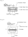
- FIG. 1 is a cross-sectional view of a first embodiment of the acceleration sensor according to the present invention
- FIG. 2 is a plan view of a lower sensor case of the first embodiment of the acceleration sensor according to the present invention. They show the basic arrangement of the acceleration sensor according to the present invention.
- an acceleration sensor 1 comprises a lower sensor case 2 formed therein with a cavity 4 and a bridge 5 by, for example, etching a semiconductor substrate with a fine-processing technique in the semiconductor manufacturing process, and an upper sensor case 3 formed therein with a cavity 7 by etching a semiconductor substrate, a closed space 8 being formed by joining the cases so that the cavities 4 and 7 abut each other.
- the closed space 8 is filled with an inert gas with a low heat transfer coefficient such as nitrogen or argon under pressure.
- metal such as platinum-is vapor-deposited on the surface of the bridge 5 of the lower sensor case 2, and etched to form a heat-type temperature-sensing resistor element 6 with a desired pattern.
- the bridge 5 is formed to bridge the center of the cavity 4 of the lower sensor case 2. Etching and vapor evaporation are controlled to accurately position the heat-type temperature-sensing resistor element 6 at the center of the closed space 8 when the acceleration sensor 1 is constructed.
- An electrode 9 formed by the same material as the heat-type temperature-sensing resistor element 6 is provided on the extension of the heat-type temperature-sensing resistor element 6 to electrically determine changes in the resistance of the heat-type temperature-sensing resistor element 6 which is caused by detecting the supply from an external power supply and the action of acceleration (G).
- a thermal equilibrium state with a steep temperature gradient is previously attained by heating the heat-type temperature-sensing resistor element 6 with the supply from the external power supply through the electrode 9.
- the sensor cases 2 and 3, the bridge 5, and the heat-type temperature-sensing resistor element 6 are formed by etching or vacuum evaporation with a fine-processing technique in the semiconductor manufacturing process so that a very small acceleration sensor several millimeters square can be constructed and so that the acceleration can be detected with a quick response and high accuracy.
- the first embodiment has the sensor case constructed of a semiconductor substrate, it may also be constructed of an insulating substrate such as glass or ceramic.
- the upper sensor case 3 is not limited to the semiconductor or insulating substrate, but may be constructed of glass or metal.
- the senor may comprise merely the lower sensor case 2 and the heat-type temperature-sensing resistor element 6, without the need necessarily for the upper sensor case 3.
- the sensor may then lie, in use, in a space in a body on which the sensor is mounted.
- the sensor could be mounted on a plate bolted over a small recess in the body such that the sensor lies in the recess. This may be true of later embodiments also.
- the sensor case, the bridge, the heater, the temperature-sensing resistor element, and the heat-type temperature-sensing resistor element are formed by using fine-processing technology of the semiconductor manufacturing process.
- a photoengraving process for making substrate 2 may comprise the steps of depositing an oxide coating such as SiN on a silicon substrate, depositing platinum or another suitable metal on the SiN, etching the metal to form resistor element patterns, possibly depositing a further oxide coating such as again SiN over the metal patterns, and etching the silicon substrate beneath the oxide coating and metal to make a cavity 4 with a bridge (5) thereabove of the oxide coating with the metal etched patterns thereon.
- the substrate 3 may also be etched to produce the cavity 7 therein. Both substrates may be placed in an oven and joined with thermosetting resin.
- the oven may be filled with for example Ar gas, which may be under pressure, for example at over one atmosphere, so that the closed space 2 of the sensor is filled with pressurised Ar gas.
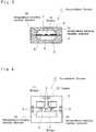
- FIG. 3 is a cross-sectional view of a second embodiment of the acceleration sensor according to the present invention
- FIG. 4 is a plan view of a lower sensor case of the second embodiment of the acceleration sensor according to the present invention. They show an embodiment for detecting the absolute value and the direction of acceleration action (G) acting on the acceleration sensor.
- an acceleration sensor 11 comprises a lower case 2 formed therein with a cavity 4 and bridges 5 and 15 by, for example, etching in a semiconductor substrate with a fine-processing technique in the semiconductor manufacturing process, and an upper sensor case 3 formed therein with a cavity 7 by etching a semiconductor substrate, a closed space 8 being formed by joining the cases so that the cavities 4 and 7 abut each other.
- a heater 12 at the center of the bridge 5 in the longitudinal direction, temperature-sensing resistor elements 13,14 opposite each other at a predetermined distance from the center of the bridge 5 in the longitudinal direction, and a lead pattern formed by using vacuum evaporation and etching of a fine-processing technique.
- the bridge 15 is formed coplanar with and perpendicular to the bridge 5, and has a lead pattern for the heater 12 thereon formed by depositing the same metal as for the heater 12 on its surface, and by etching the metal.
- the temperature-sensing resistor elements 13 and 14 are formed in such a manner that a metal pattern is formed by depositing high-melting-point metal such as Pt, Mo, Ni, Au, or Ti, and then etching the metal to form each temperature resistor element with a pattern having a predetermined resistance.
- high-melting-point metal such as Pt, Mo, Ni, Au, or Ti
- the surface of the temperature-sensing resistor elements 13, 14 formed by etching is coated by an oxide coating which is formed by an oxide such as SiN.
- the pair of temperature-sensing resistor elements 13, 14 and the heater 12 are connected through the lead pattern to respective electrodes 9 provided on the periphery of the lower sensor case 2, electrodes 9 being connected to an external power supply or a detector circuit.
- the heater 12 is heated by supplying external power through the electrode 9 to previously create a thermal equilibrium state with a steep temperature gradient in the closed space 8.
- the temperature-sensing resistor elements 13 and 14 are in the same temperature atmosphere so that each of them exhibits the same resistance value if their resistance and characteristics of temperature coefficient are matched (paired).
- acceleration (G) acts in the equilibrium state in the direction shown in FIG. 4 (indicated by a solid arrow or broken arrow)
- an air flow is generated in the inert gas, such as nitrogen or argon, enclosed in the closed space 8 to create a thermally unbalanced state in the direction of acceleration action (G) so that the temperature-sensing resistor elements 13 and 14 are subject to different temperatures, respectively.
- the absolute value and the direction of acceleration action (G) are detected by electrically detecting the change in resistance.
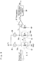
- FIG. 5 shows the arrangement of a detection circuit of the acceleration sensor of FIG. 4.
- a detector circuit comprises a bridge circuit 16, and reference resistors R1 and R2, and an amplifier 18 which amplifies the differential output of the bridge circuit 16, wherein the bridge circuit 16 constitutes a resistor bridge by connecting the temperature-sensing resistor elements 13 and 14, which is externally provided through the electrodes 9, and reference resistors R1 and R2.
- a power supply 17 applies power to the bridge circuit 16.
- the temperature-sensing resistor elements 13 and 14 exhibit different resistance values (R X1 > R X2 or R X1 ⁇ R X2 ), and the bridge circuit 16 supplies to the amplifier 18 a bridge output (voltage) with negative (-) or positive (+) polarity, depending on the absolute value and the direction of acceleration action (G), and detects the output V a corresponding to the bridge output from the amplifier 18.
- temperature-sensing elements 13 and 14 are formed by a fine-processing technique of the semiconductor manufacturing process, it is possible to accurately provide resistance (R X1 , R X2 ) in a paired state so that the offset of the bridge output (voltage) can be set to a value as close to zero as possible.
- the acceleration sensor 11 employs nitrogen gas with a heat transfer coefficient of about 0.024 (kcal/m ⁇ h ⁇ °C) as the gas enclosed in the closed space 8.
- the acceleration sensor 11 can detect acceleration (G) acting on the acceleration sensor with high sensitivity because the closed space 8, the heater 12, and the temperature-sensing resistor elements 13 and 14 can be constructed by using a fine-processing technique of the semiconductor manufacturing process, and their positions can be precisely determined so that a very small acceleration sensor on a millimeter order can be easily obtained.
- the acceleration sensor 11 separately provides the heater 12 and the temperature-sensing resistor elements 13 and 14, which are positioned opposite to the direction to which acceleration (G) occurs, so that the absolute value and the direction of acceleration (G) acting on the acceleration sensor can be detected with high accuracy.
- the acceleration sensor is constructed without using the fine-processing technique of the semiconductor manufacturing process as in the conventional sensor, the ability to reduce its size is limited, and the positioning accuracy of the heater and the temperature-sensing resistor elements in the closed space and the pairing of temperature-sensing resistor elements cannot be fully satisfied, with the result that the sensitivity and accuracy in the detection of acceleration (G) are deteriorated.
- FIG. 6 shows a plan view of a lower sensor case of a third embodiment of the acceleration sensor according to the present invention.
- an acceleration sensor 21 differs from the acceleration sensor 11 of FIG. 4 in that, in place of the temperature-sensing resistor elements 13 and 14, heat-type temperature-sensing resistor elements 19 and 20 are positioned opposite to each other to eliminate the heater 12 and the bridge 15.
- heat-type temperature-sensing resistor elements 19 and 20 themselves serve as both heaters and temperature-sensing resistor elements, it is possible to create a thermal equilibrium state in temperature distribution with two heaters, and to detect an unbalanced state in the temperature distribution caused by the action of acceleration (G) with two temperature-sensing resistor elements.
- FIGS. 7 and 8 are the arrangement of a fourth embodiment of the acceleration sensor according to the present invention.
- an acceleration sensor 31 comprises an upper sensor case 3 formed therein with a cavity, a lower sensor case 2 having a cavity 4, a heater 32, and a temperature-sensing resistor element 33, the latter two components being provided at bridges of the cavity 4.
- a gas 34 is enclosed in a closed space formed by the upper and lower cavities.
- the heater 32 and the temperature-sensing resistor element 33 are resistors which are formed by depositing and etching platinum or tungsten on a bridge (not shown).
- the gas 34 is a pressurized gas with a low heat transfer coefficient such as nitrogen gas or argon.
- the lower sensor case 2 and the upper sensor case 3 are closely attached and joined.
- the heater 32 is driven by an external power supply through lead wires 32a and 32b, and generates temperature sufficiently higher than the ambient temperature.
- the temperature-sensing resistor 33 is previously adjusted to have a predetermined resistance value by supplying a small current from the external power supply through lead wires 33a and 33b.
- the heat generated from the heater 32 is transferred through the gas 34 to create a temperature distribution corresponding to the distance from the heater 32.
- a pressurized gas with a low heat transfer coefficient such as nitrogen gas or argon creates temperature distribution with a steep temperature gradient corresponding to the distance from the heater 32.
- the resistance also rises, if the temperature coefficient is positive, to increase the value of the voltage to be detected on the lead wires 33a and 33b.
- acceleration (G) acts in the opposite direction (to the right)
- the heated gas 34 moves to the left to reduce the temperature of the temperature-sensing resistor element 33 and also to lower the resistance value of the temperature-sensing resistor element 33 so that the value of the voltage to be detected on the lead wires 33a and 33b is reduced.
- the heater 32 and the temperature-sensing resistor element 33 are positioned on a bridge (not shown) at a predetermined distance D.
- the acceleration sensor 31 is constructed by positioning the heater 32 and the temperature-sensing resistor element 33, enclosing the pressurized gas with a low heat transfer coefficient such as nitrogen gas or argon in the closed space to increase the temperature gradient and to detect the temperature with a steep temperature gradient from the heater 32, it can detect the temperature change from the change of acceleration (G) with high accuracy.
- a low heat transfer coefficient such as nitrogen gas or argon
- FIG. 9 shows a functional block diagram for the detection of acceleration by using the acceleration sensor of FIGS. 7 and 8.
- the heater 32 is driven by a constant current source (I H ) 35, and generates heat at a high temperature corresponding to the power (R H *I H 2) based on the resistance R H and the current I H .
- the temperature-sensing resistor element 33 is driven by a constant current source (I L ) 36, set to a resistance value R C which is the sum of a resistance value at the ordinary temperature and a resistance value corresponding to the temperature transferred from the heater 32, and outputs the voltage at a value V C (R C *I L ).
- the voltage V G is an output of the acceleration sensor 31 corresponding to the resistance R C when no acceleration (G) acts, and input to one terminal (for example, the positive input terminal) of a comparator 37 which is constituted by, for example, an operational amplifier.
- the other terminal (for example, a negative input terminal) of the comparator 37 is input with a voltage V S from a reference resistor R S .
- An acceleration conversion means 38 has a memory such as a ROM which stores, beforehand, a value of the acceleration G O corresponding to the difference ⁇ V, and is arranged to output an acceleration signal G O in response to the input of the difference ⁇ V.
- the acceleration sensor 31 comprises the heater which heats the gas to create a temperature distribution in the space, and the temperature-sensing resistor element which, when acceleration acts on the sensor case, detects a temperature change from the movement of the gas with the temperature distribution so that it can detect the absolute value and the direction of acceleration action.
- the acceleration sensor can maintain stable sensitivity while preventing the deterioration or aging which may be caused by high temperature.
- the acceleration sensor 31 employs a pressurized gas with a low heat transfer coefficient as the gas to be enclosed, and can heighten the sensitivity to the temperature detected with the steep temperature gradient so that the acceleration corresponding to the detected temperature can be detected with high accuracy.
- FIGS. 10 and 11 are the arrangement of a fifth embodiment of the acceleration sensor according to the present invention.
- an acceleration sensor 41 differs from the acceleration sensor 31 shown in FIGS. 7 and 8 in that a temperature-sensing resistor element for temperature compensation 42 is disposed in a cavity 44 formed in a lower sensor case 2 or outside the lower sensor case 2.
- the cavity 44 is formed separately from a cavity 43 to avoid the influence of the heat from the heater 32. Air is enclosed in the closed space so that the temperature-sensing resistor element for temperature compensation 42 detects the ambient temperature.
- the temperature-sensing resistor element for temperature compensation 42 is arranged on a bridge in the cavity 44, it is formed on the same semiconductor substrate as for the heater 32 and the temperature-sensing resistor element 33 by using a fine-processing technique of the semiconductor manufacturing process.
- the temperature-sensing resistor element for temperature compensation 42 and the temperature-sensing resistor element 33 are formed on the same semiconductor substrate with the same semiconductor manufacturing process, the temperature-sensing resistor elements with the same characteristics can be formed so that variations in the characteristics and aging between both temperature-sensing resistor elements can be compensated for.
- the temperature-sensing resistor element for temperature compensation 42 When the temperature-sensing resistor element for temperature compensation 42 is disposed outside the lower sensor case 2 (the upper sensor case 3 being included), it is attained by attaching, for example, by bonding, to the case the temperature-sensing resistor element for temperature compensation 42 with temperature characteristics matching those of the temperature-sensing resistor element 33.
- the heater 32, the temperature-sensing resistor element 33, and the temperature-sensing resistor element for temperature compensation 42 are at ambient temperature.
- the heater 32 when current is supplied to the heater 32, the heater 32 generates heat corresponding to the power consumption determined by the supplied current and resistance, and thus is heated. It has a temperature equal to the sum of the temperature from the consumed power and the ambient temperature.
- the heat generated from the heater 32 is transferred to the gas 34 such as nitrogen gas or argon to create a temperature distribution with a steep temperature gradient, which is detected by the temperature-sensing resistor element 33. Since the gas 34 and the temperature-sensing resistor element 33 were previously at ambient temperature, the temperature detected by the temperature-sensing resistor 33 is also the sum of the temperature transferred from the heater 32 and the ambient temperature.
- the gas 34 such as nitrogen gas or argon
- the temperature of the heater 32 is the temperature from the consumed power added to the predetermined temperature ⁇ T
- the temperature detected by the temperature-sensing resistor element 33 is also the temperature of temperature distribution at the location where the temperature-sensing resistor element 33 is positioned added to the predetermined temperature ⁇ T.
- the temperature-sensing resistor element for temperature compensation 42 is also set to the ambient temperature (the reference temperature 20°C plus the predetermined temperature ⁇ T), it is possible to compensate for the temperature detected by the temperature-sensing resistor element 33 based on the temperature detected by the temperature-sensing resistor element for temperature compensation 42.
- temperature compensation can be attained based on the temperature detected by the temperature-sensing resistor element for temperature compensation 42.
- FIG. 12 shows a functional block diagram for the detection of acceleration by using the acceleration sensor of FIGS. 10 and 11.
- the heater 32 and the temperature-sensing resistor element 33 are driven by a constant-current source (I H ) 35 and a constant-current source (I L ) 36, respectively, and the temperature-sensing resistor element for temperature compensation 42 is driven by a constant-current source (I L ) 45 with the same current as that for the temperature-sensing resistor element 33.
- An acceleration correction means 46 comprising a temperature comparator 47, a correction value output means 48, and a correction value memory 49, corrects the detection output V G from the temperature-sensing resistor element 33 based on the detection output V R from the temperature-sensing resistor element for temperature compensation 42 to compensate for the variation in the acceleration (G) due to the ambient temperature to allow the actual acceleration G O acting on the acceleration sensor to be determined.
- the temperature comparator 47 consists of a comparator circuit such as a comparator, and stores, beforehand, the detection output V R provided by the temperature-sensing resistor element for temperature compensation 42. It compares the detection output V R with a reference voltage V f corresponding to 20°C, and outputs the difference ⁇ V R between the detection output V R and the reference voltage V f to the correction value output means 48.
- the correction value output means 48 receives the detection output V G from the temperature-sensing resistor element 33 and the difference ⁇ V R , reads an acceleration correction value ⁇ G corresponding to the detection output V G and the difference ⁇ V R from the correction value memory 49, and provides it to the acceleration conversion means 38.
- the correction value output means 48 is set to make the acceleration correction value ⁇ G to be output as zero when no acceleration (G) acts at an ambient temperature of, for example, 20°C.
- the correction value memory 49 consists of a memory such as a ROM and sets, in a table, a correction value ⁇ G when the difference ⁇ V R changes, which correction value is previously determined through experiments for a reference of a difference (V G - ⁇ V R ) between the detection output V R and the difference ⁇ V R based on the detection output V R and the difference ⁇ V R .
- the acceleration conversion means 38 comprises a memory such as a ROM for converting the detection output V G to a corresponding acceleration G O , and a subtractor.
- the conversion means (38) converts the detection output V G to acceleration G O , then calculates the difference (G O - ⁇ G) of the correction value ⁇ G from the acceleration G O , and outputs the difference as the acceleration G O .
- the acceleration conversion means 38 is set to make the acceleration G O to be output to zero when no acceleration (G) acts at an ambient temperature of, for example, 20°C.
- the acceleration G O to be output is set to zero when no acceleration (G) acts at an ambient temperature of 20°C, and the acceleration correction means 46 compensates for the temperature according to the change in the ambient temperature, it is possible to set the acceleration G O output from the acceleration conversion means 38 always to zero.
- acceleration (G) acts, as the detection voltage V G of the temperature-sensing resistor element 33 increases or decreases, the acceleration G O corresponding to the detection output V C and corrected for the acceleration with respect to the ambient temperature (correction value ⁇ G) can be obtained from the acceleration conversion means 38.
- the acceleration correction means 46 is an embodiment of an arrangement assuming a case where the ambient temperature changes from the temperature detected at a state where the temperature-sensing resistor element 33 is at the ambient temperature of 20°C and no acceleration (G) occurs, and where the output G O from the acceleration conversion means 38 corresponding to the detection output V C is nonlinear.
- FIG. 13 shows another embodiment of the acceleration correction means in FIG. 12.
- This embodiment represents a case in which the output G O from an acceleration conversion means 50 and the detection output V GO from an acceleration correction means 46' are linear.
- the acceleration correction means 46' comprises a comparator circuit such as a comparator and an arithmetic circuit such as a subtractor, and calculates and outputs a difference V GO (V G - V R ) between the detection output V G from the temperature-sensing resistor element 33 and the detection output V R from the temperature-sensing resistor element for temperature compensation 42.
- the acceleration conversion means 50 has a memory such as a ROM for converting the difference output V GO from the acceleration correction means 49 into a corresponding acceleration G O , converts the difference output V GO into acceleration G O , and outputs it.
- a memory such as a ROM for converting the difference output V GO from the acceleration correction means 49 into a corresponding acceleration G O , converts the difference output V GO into acceleration G O , and outputs it.
- the acceleration sensor 41 since the acceleration sensor 41 according to the present invention comprises the temperature-sensing resistor element for temperature compensation for detecting the ambient temperature, and the acceleration correction means for correcting the output signal output from the temperature-sensing resistor element based on the output signal from the temperature-sensing resistor element for temperature compensation, it can detect accurately the acting acceleration by compensating for the influence from the ambient temperature.
- FIGS. 14 and 15 are the arrangement of a sixth embodiment of the acceleration sensor according to the present invention.
- an acceleration sensor 51 comprises an upper sensor case 3 formed therein with a cavity, a lower sensor case 2 having a cavity 4, temperature-sensing resistor elements 52 and 53 provided on bridges in the cavity 4, and a pair of reference resistors 54 and 55 externally connected to the temperature-sensing resistor elements 52 and 53 to form a bridge circuit 56, a gas 34 being enclosed in a closed space formed by the upper and lower sensor cases.
- the heat-type temperature-sensing resistor elements 52 and 53 comprise resistors, each of which is formed by depositing and etching platinum or tungsten on a bridge (not shown).
- the gas 34 employed is a pressurized gas with a low heat transfer coefficient such as nitrogen gas or argon.
- the lower sensor case 2 and the upper sensor case 3 are closely attached and joined.
- the heat-type temperature-sensing resistor elements 52 (resistor R1) and 53 (resistor R2) are connected by lead wires which are led outside of the sensor case for connecting with the reference resistors 54 (resistor r1) and 55 (resistor r2), which are disposed outside the sensor case, to form a bridge circuit 56.
- the bridge circuit 56 has terminals (56a - 56d), as shown in FIG. 15, and consists of four resistors.
- the heat-type temperature-sensing resistor elements 52 and 53 When power (for example, from a power supply V I ) is applied across the terminals (56a - 56b), the heat-type temperature-sensing resistor elements 52 and 53 generate heat corresponding to the power consumed, and generate, as a heat source with a temperature sufficiently higher than the ambient temperature, a temperature distribution corresponding to the distance from the heat-type temperature-sensing resistor elements 52 and 53 in the closed space.
- the heat-type temperature-sensing resistor elements 52 and 53 have resistances R1 and R2, respectively, so that voltage V X divided by the resistor R1 and R2 is generated at the terminal (56c).
- the employment of the pressurized gas with a low heat transfer coefficient, such as nitrogen gas or argon, as the gas 34 results in a temperature distribution corresponding to the distance from the heat-type temperature-sensing resistor elements 52 and 53 in the closed space with a steep temperature gradient.
- acceleration (G) acts in the direction indicated by the arrow shown in FIG. 15 in the equilibrium state
- the gas 34 moves in the direction of P to cause heat movement from the heat-type temperature-sensing resistor element 52 to the heat-type temperature-sensing resistor element 53.
- the acceleration sensor 51 detects the magnitude of the acting acceleration (G) with the absolute value of the output of the bridge circuit 56 (potential difference V X - V Y ), and the acting direction of acceleration (G) with the sign of the output (positive or negative of potential difference V X - V Y ).
- FIG. 16 shows a bridge circuit diagram in the acceleration sensor of FIGS. 14 and 15.
- the bridge circuit 56 consists of the resistances R1 and R2 of the heat-type temperature-sensing resistor elements 52 and 53, and the resistances r1 and r2 of the reference resistors 54 and 55, a power supply (for example, the voltage source V I ) being connected between the terminals (56a - 56b), the output occurring across the terminals (56c - 56d).
- a power supply for example, the voltage source V I
- V X R2 * V I /(R1 + R2)
- V Y r2 * V I /(r1 + r2)
- the output potential difference V O can provide a value proportional to the variation ⁇ R of resistance corresponding to acceleration (G).
- a pair of heat-type temperature-sensing resistor elements is disposed with a predetermined distance in a closed space containing a pressurized gas with a low heat transfer coefficient, and a bridge circuit is constituted by a pair of heat-type temperature-sensing resister elements and a pair of external reference resistors, it is possible to detect heat movement in the case, which is caused by the action of acceleration, with the change in resistance of the pair of heat-type temperature-sensing resistor elements, to detect the absolute value of acceleration at a high accuracy with the output voltage of the bridge circuit and its sign, and to detect the direction in which acceleration is acting.
- FIGS. 17 and 18 are the arrangement of a seventh embodiment of the acceleration sensor according to the present invention.
- the acceleration sensor 61 differs from the acceleration sensor 51 shown in FIG. 14 in that heat-type temperature-sensing resistor elements 62 and 63 are disposed at a predetermined distance D in a closed space in a lower sensor case 2, and a plurality of heaters 64 (R11 - R 1n , R21 - R 2n , R31 - R 3n ) are positioned on both sides of the heat-type temperature-sensing resistor elements 62 and 63.
- the heat-type temperature-sensing resistor elements 62 and 63, and the reference resistors 54 and 55 constitute the bridge circuit 56 shown in FIG. 15.
- the heaters 64 (R11 - R 1n , R21 - R 2n , R31 - R 3n ) are heated by, for example, connecting the elements in series and connecting a power supply across the terminals (56e - 56f).
- a voltage source V I is connected across the terminals (56a - 56b) of the bridge circuit 56 to heat the heat-type temperature-sensing resistor elements 62 and 63.
- the heat-type temperature-sensing resistor elements 62 and 63 have resistances R1 and R2 when the temperature distribution in the closed space caused by the heat generation of the heat-type temperature-sensing resistor elements 62 and 63, and the heaters 64 (R11 - R 1n , R21 - R 2n , R31 - R 3n ) reaches equilibrium.
- the acceleration sensor 61 is provided with a plurality of heaters 64, the movement of heat (temperature change) can be set at a linear value, and provide larger bridge output than that of the arrangement of FIG. 14 can be obtained for the same acceleration (G) so that the detection accuracy can be improved.
- the acceleration sensor 61 since the acceleration sensor 61 according to the present invention provides a plurality of heaters together with a pair of heat-type temperature-sensing resistor elements in the closed space, the heat movement (temperature change) in the closed space can be increased so that the absolute value of acceleration can be detected with a high accuracy.
- FIGS. 19 and 20 are the arrangement of a eighth embodiment of acceleration sensor according to the present invention.
- an acceleration sensor 71 differs from the arrangements shown in FIGS. 14 and 15 in that heat-type temperature-sensing resistor elements 74 and 75 corresponding to the standard resistor (r1) 54 and the standard resistor (r2) 55 shown in FIG. 15 are provided in the closed space in the lower sensor case 2 together with the heat-type temperature-sensing resistor elements 72 and 73, and in that a bridge circuit 56 is constituted by the heat-type temperature-sensing resistor elements 72, 73, 74 and 75.
- a power supply V I is connected across the terminals (56a - 56b) to heat the heat-type temperature-sensing resistor elements 72, 73, 74, and 75.
- the acceleration sensor 71 provided with the heat-type temperature-sensing resistor elements 74 and 75 can set the movement of heat (temperature change) to a large value, and a larger bridge output can be obtained for the same acceleration (G) than for the arrangements of FIGS. 14 and 15 so that the detection accuracy of the sensor can be made higher.
- the acceleration sensor 71 since, in the acceleration sensor 71 according to the present invention, two pairs of heat-type temperature-sensing resistor elements are provided in the closed space, and the bridge circuit is constituted by four heat-type temperature-sensing resistor elements, the absolute value of acceleration can be detected at a higher accuracy.
- FIG. 21 is the arrangement of essential components of a ninth embodiment of an acceleration sensor according to the present invention.
- an acceleration sensor 81 is an embodiment of a three-axis acceleration sensor, and constituted by four types of semiconductor substrates 82 - 85.
- the semiconductor substrates 82 - 85 are formed therein with a cavity, a space, heaters, and temperature-sensing resistor elements by a fine-processing technique in the semiconductor manufacturing process such as etching or depositing.
- the semiconductor substrate 82 constitutes the cover for a sensor case for the acceleration sensor 81 in which a cavity 86 is very finely processed and formed by etching.
- the semiconductor substrate 83 is formed with a temperature-sensing resistor element Z1 upward in the direction of the Z axis, external connection pads (91a) and (92b) for connecting the temperature-sensing resistor element Z1 to the outside, and a space 87 extending through the Z axis.
- the temperature-sensing resistor element Z1 is formed by etching based on a fine pattern diagram which represents a mask for manufacturing conductors to be formed on a bridge (not shown), which is formed on the top of the semiconductor substrate by, for example, etching, by depositing or crystal growing metal such as platinum or tungsten.
- the temperature-sensing resistor element Z1 is formed on the diagonal line, or in the X direction, or in the Y direction, so that it is positioned at the center of the top of the substrate.
- the external connection pads (91a) and (91b), and a lead pattern for electrically connecting the temperature-sensing resistor element Z1 and the external connection pads (91a) and (91b) are also formed by depositing or crystal growing metal such as platinum or tungsten as in the temperature-sensing resistor element Z1.
- the semiconductor substrate 83 is formed of a sufficiently large size so that the external connection pads (91a) and (91b) appear on the surface of the substrate when it is stuck together with the semiconductor substrate 82, and the upper surface of the space 87 aligns the plane of the cavity 86 in the semiconductor substrate 82.
- the semiconductor substrate 84 includes a heater H, pairs of temperature-sensing resistor elements X1 and X2, and Y1 and Y2 facing the heater H and respectively disposed in the directions of the X and Y axes, external connection pads (93a, 93b, 94a, 94b, 95a, 95b, 96a, 96b, 97a, and 97b) for connecting the heater H, and the temperature-sensing resistor elements X1, X2, Y1, and Y2 to the outside, and a space 88 extending through the Z axis.
- the heater H is formed so as to be positioned at the center of the space 88 on the top of the semiconductor substrate 84.
- the heater H, and the pairs of temperature-sensing resistor elements X1 and X2, and Y1 and Y2 are formed by depositing and etching metal such as platinum and tungsten on a bridge (not shown) which is formed by etching as in the temperature-sensing resistor element Z1 on the semiconductor substrate 83.
- the heater H and the temperature-sensing resistor elements X1, X2, Y1, and Y2 differ in that the resistance of the heater H is lower than the temperature-sensing resistor elements X1, X2, Y1, and Y2.
- a lead pattern is also formed by deposition or the like and etching metal such as platinum or tungsten for electrically connecting the heater H and the temperature-sensing resistor elements X1, X2, Y1, and Y2 to the external connection pads (93a, 93b, 94a, 94b, 95a, 95b, 96a, 96b, 97a, and 97b).
- the space 88 is formed in the same size as the space 87 to pass through the Z axis.
- the semiconductor substrate 84 is formed of a sufficiently large size so that the external connection pads (93a, 93b, 94a, 94b, 95a, 95b, 96a, 96b, 97a, and 97b) appear on the surface of the substrate when it is stuck together with the semiconductor substrate 83, and the upper surface of the space 88 aligns the plane of the space 87 in the semiconductor substrate 83.
- the semiconductor substrate 85 is formed with a temperature-sensing resistor element Z2 downward in the direction fo the Z axis, external connection pads (92a) and (92b) for connecting the temperature-sensing element Z2 to the outside, and a space 89 which forms the bottom of the sensor 81 case downward in the direction of the Z axis.
- the temperature-sensing resistor element Z2 is arranged to be paired with the temperature-sensing resistor element Z1 on the semiconductor substrate 83 with respect to the heater H on the semiconductor substrate 84.
- the temperature-sensing resistor element Z2 is formed in a manner similar to that for the temperature-sensing resistor element Z1 on the semiconductor substrate 83.
- the semiconductor substrate 85 is formed of a sufficiently large size so that the external connection pads (92a) and (92b) appear on the surface of the substrate when it is stuck together with the semiconductor substrate 84, and the upper surface of the space 89 aligns the plane of the space 88 in the semiconductor substrate 84.
- the semiconductor substrates 83, 84 and 85 are stacked and joined in the direction of the Z axis direction so as to align the spaces 87 - 89, and a pressurized gas with a low heat transfer coefficient such as nitrogen or argon is introduced into the space while joining the semiconductor substrate 82 to form a pyramid acceleration sensor 81.
- a pressurized gas with a low heat transfer coefficient such as nitrogen or argon
- Positioning recesses may be provided in the upper surfaces of the semiconductor substrates 83 - 85 in joining the semiconductor substrates 82 - 85.
- a two-axis (X and Y axes) acceleration sensor can be constituted by eliminating the semiconductor substrates 83 and 85, and providing a bottom on the space 88 in the semiconductor substrate 84 similar to the space 89 in the semiconductor substrate 85.
- the thus-constituted acceleration sensor 81 can attain accurate positioning of the heater H and the temperature-sensing resistor elements X1, X2, Y1, Y2, Z1, and Z2 by using a fine-processing technique in the semiconductor manufacturing process so that alignment can be accurately achieved,
- the acceleration sensor 81 can be obtained with good pairing (resistivity and temperature coefficient) of X1 and X2, Y1 and Y2, and Z1 and Z2.
- the acceleration sensor 81 is formed by the fine-processing technique in the semiconductor manufacturing process, it can be produced in the minimum size necessary for a sensor so that miniaturization can be attained.
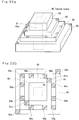
- FIGS. 22a and 22b show in perspective and top plan view the appearance of the acceleration sensor shown in FIG. 21.
- the acceleration sensor 81 has the semiconductor substrates 82 - 85 described for FIG. 21, and is constituted in a pyramid acceleration sensor by stacking and joining the semiconductor substrates 82 - 85 in the direction of the Z axis.
- the heater H Disposed in the closed space 90 are the heater H, and the temperature-sensing resistor elements X1, X2, Y1, Y2, Z1, and Z2 for detecting acceleration in the three axes (X, Y, and Z axes).
- the pressurized gas 91 with a low heat transfer coefficient such as nitrogen or argon is also enclosed in the space 90.
- the acceleration sensor 81 disposed on the surface of the acceleration sensor 81 are the external connection pads of the heater H (bonding pads 91a - 97b) and of the temperature-sensing resistor elements X1, X2, Y1, Y2, Z1, and Z2 for connection with an external acceleration detector circuit (not shown).
- FIG. 23 is a diagram illustrating the operation of the acceleration sensor shown in FIG. 21.
- the heater H is disposed at the center of the X-Y plane at the center of the Z axis, and a pair of temperature-sensing resistor elements X1 (resistance R1) and X2 (resistance R2); and a pair of temperature-sensing resistor elements Y1 (resistance R3) and Y2 (resistance R4) are disposed opposite to each other with respect to the X and Y axes, respectively, in symmetry with the heater H (resistance R).
- a pair of temperature-sensing resistor elements Z1 (resistance R5) and Z2 (resistance R6) is disposed opposite to each other with respect to the Z axis in symmetry with the heater H (resistance R).
- a pressurized gas 91 with a low heat transfer coefficient such as nitrogen or argon.
- the heater H generates Joule heating corresponding to the electrical power (V O 2/R or I O 2*R) by driving it with an external power supply (for example, a voltage source V O or a current source I O ).
- the gas 91 is heated by Joule heating, and a temperature distribution inversely proportional to the distance from the heater H is created in the closed space 90 with a steep temperature gradient.
- the resistance difference (R1 - R2) becomes a positive value (R1 - R2 > 0) so that the magnitude of acceleration (G) can be detected from the value corresponding to the resistance difference, and the direction of acceleration (G) can be detected from the sign (+ or -) of the resistance difference.
- acceleration (G) acts in the direction of the Y or Z axis
- the thermal balance is destroyed in the temperature-sensing resistor elements Y1 and Y2 or Z1 and Z2 positioned in the direction of acceleration (G) so that the acceleration (G) can be detected from a value corresponding to the resistance difference (R3 - R4) or (R5 - R6) and their sign (+ or -).
- FIGS. 24 - 27 are diagrams of acceleration detector circuits of the acceleration sensor shown in FIG. 21.
- FIG. 24 shows a diagram of the heater driving circuit
- FIG. 25 a diagram of the acceleration detector circuit in the direction of the X axis
- FIG. 26 a diagram of the acceleration detector circuit in the direction of the Y axis
- FIG. 27 a diagram of the acceleration detector circuit in the direction of the Z axis.
- FIGS. 24-27 show examples in which the driving power supply is constituted by a current source (I O ), they may be constituted by a voltage source (V O ).
- the heater driving circuit shown in FIG. 24 supplies current to the resistance R of the Heater H from a current source (I O ) to generate Joule heating corresponding to the electrical power (I O 2*R).
- the acceleration detector circuit in the direction of the X axis shown in FIG. 25 constitutes a resistor bridge circuit with the temperature-sensing resistor elements X1 (resistance R1) and X2 (resistance R2), and standard resistors Ro1 and Ro2, and is arranged to output difference V OX (V X1 - V X2 ) based on the bridge output voltage V X1 and V X2 through a differential amplifier A X , and to obtain a detection output corresponding to acceleration (G) acting in the direction of the X axis.
- FIGS. 26 and 27 similarly constitute a resistor bridge circuit, and are arranged to output difference V OY (V Y1 - V Y2 ) and V OZ (V Z1 - V Z2 ) based on the bridge output voltage V Y1 and V Y2 , as well as V Z1 and V Z2 , and to obtain a detection output corresponding to acceleration (G) acting in the direction of the Y or Z axis direction.
- acceleration (G) acting in the X, Y and Z axis directions can be detected from the difference (V OX , V OY and V OZ ) and their sign (+ or -), it is possible to detect acceleration (G) acting in any of three dimensional directions by providing a calculation means for calculating the mean square ⁇ (V OX 2 + V OY 2 + V OZ 2) and an orientation determination means for determining the quadrant of a three-dimensional XYZ coordinate system from the sign (+ or -) of each difference.
- the acceleration sensor 81 is arranged by forming the sensor case forming the closed space, the heaters, a pair of temperature-sensing resistor elements disposed in each of multiple axis directions on a plurality of separate semiconductor substrates with the semiconductor manufacturing process, and by joining the plurality of semiconductor substrates in one direction, it is possible to easily align the plurality of temperature-sensing resistor elements with the multiple axes which are orthogonal to each other, and to form the temperature-sensing resistor elements with matched characteristics so that a very small acceleration sensor can be attained with less variation and higher accuracy.
- the acceleration sensor 81 since the acceleration sensor 81 according to the present invention employs pressurized gas with a low heat transfer coefficient as the gas to be enclosed in the closed space, it is possible to create a steep temperature gradient and to attain a sensor with high sensitivity.
- the present invention very finely processes the semiconductor substrates and the like with a fine-processing technique in the semiconductor manufacturing process, accurately forms the sensor case, the heater, the temperature-sensing resistor element, the heat-type temperature-sensing resistor element and the like, and accurately determines their relative placement, the present invention can provide a miniaturized and economic acceleration sensor which can detect acceleration acting on the sensor with a high accuracy.
- the present invention encloses a pressurized inert gas with a low heat transfer coefficient in the closed space formed by the sensor case, the present invention can provide an acceleration sensor which can detect acceleration acting on the sensor with a high sensitivity by increasing the temperature gradient in the closed space.
- the present invention disposes a pair of temperature-sensing resistor elements with good pairing (resistivity, and temperature coefficient) in the direction of acceleration, it can provide an acceleration sensor which can detect the absolute value and the direction of acceleration more accurately.
- the present invention disposes a pair of temperature-sensing resistor elements with good pairing (resistivity, and temperature coefficient) in each of the three-dimensional axis directions, it can provide an acceleration sensor which can accurately detect acceleration acting in any of the three-dimensional directions.
- the embodiments describe sensors fabricated by photoengraving semiconductor or insulating substrates
- the invention encompasses sensors which comprise a heater and one or more separate temperature-sensing resistor elements, as well as sensors which comprise two or more heat-type temperature-sensing resistor elements, no matter how they are fabricated.
- Such sensors still provide advantages, such as the ability to detect acceleration direction, even though they may not be as sensitive or as small as, for example, semiconductor sensors.
Abstract
Description
- The present invention relates to an acceleration sensor for detecting acceleration acting on the sensor body, and, more particularly, to an acceleration sensor for detecting acceleration in the form of changes in the temperature distribution of gas in a closed space.
- Disclosed in Published Unexamined Patent Application No. 3-176669 is an acceleration sensor in which the equilibrium of the temperature distribution is formed by heating a gas enclosed in a space closed in a case, and the phenomenon in which the temperature distribution is changed while an air flow is generated by the action of acceleration is detected as a change in the resistance of a resistance temperature sensor disposed within the case.
- In the above conventional acceleration sensor, a thin-film-resistor temperature sensor serving also as a heater is disposed in a resin case, and heated by applying current thereto. Resistance values are previously detected for the heated thin-film-resistor temperature sensor at various temperatures.
- When acceleration acts on the acceleration sensor, an air flow is generated in the case. The generated air flow takes heat from the thin-film-resistor temperature sensor, thereby reducing its temperature so that the resistance of the thin-film-resistor temperature sensor is changed.
- Because the change in the resistance of the thin-film-resistor temperature sensor corresponds to the acceleration acting on the acceleration sensor, the acceleration is detected by converting the resistance of the thin-film-resistor temperature sensor to an electric signal.
- The conventional acceleration sensor has, however, a problem that, although it can detect the absolute value of acceleration, it cannot detect the direction in which acceleration acts because it uses the same element to act as both the heater for the gas in the case and the temperature-sensing element which detects the temperature change due to the action of acceleration.
- In addition, the conventional acceleration sensor has a problem that, because the thin-film-resistor temperature sensor for the heater serves as both a heater and a temperature-sensing element, aging from deterioration for the temperature is caused in the thin-film-resistor heating-type temperature sensor if the generated temperature is high, leading to variations in heat generation and reduced sensitivity to temperature so that the sensor cannot accurately detect acceleration.
- Moreover, the conventional acceleration sensor has a relatively bulky size for the closed space, which results in a degraded response to the temperature change by the air flow. Reduction of the size of the acceleration sensor is limited by its structure.
- Furthermore, while the accuracy of acceleration detection depends on the positional accuracy of the thin-film-resistor heating-type temperature sensor, the conventional acceleration sensor has a structure in which the thin-film-resistor heating-type temperature sensor is directly installed on the case, which makes it difficult to accurately position the thin-film-resistor heating-type temperature sensor.
- From one aspect, the invention may provide a very small acceleration sensor which is constructed by etching a semiconductor or insulating substrate using a photoengraving process in the semiconductor manufacturing process. Preferably, two sensor cases each with a cavity therein are joined together to form a closed space, with a bridge being formed at the center of one of the sensor cases at the time the cavity is formed, on which is integrally placed a temperature-sensing resistor element and a heater through the photoengraving process, the element accurately detecting imbalance in the temperature distribution generated in the closed space by acceleration acting on the sensor case as a change in resistance of the temperature-sensing resistor element.
- From another aspect the invention may provide an acceleration sensor which can accurately detect the absolute value of acceleration acting on the sensor case in any one, two or three-dimensional direction and the direction of action, for example by arranging a pair of temperature-sensing resistor elements in the sensor case in one-dimensional (X axis), two-dimensional (X and Y axes) or three-dimensional (X, Y, and Z axes) axial directions.
- As described, because the acceleration sensor is constructed by using the photoengraving process in the semiconductor manufacturing process, resistance values of the temperature-sensing resistor element and the heater and their positioning in the sensor case can be attained with high accuracy.
- Therefore, the present invention may provide an acceleration sensor which eliminates problems inherent to the conventional acceleration sensor of poor response to the detection of acceleration due to limitations in the reduction of the size, poor accuracy of acceleration detection due to an inability to accurately position the temperature-sensing resistor element and the heater, time consumed for selecting the resistance for the temperature-sensing resistor element and the heater, and the occurrence of waste parts, and which is very small in size, has excellent accuracy in acceleration detection, and is suitable for mass production.
- Embodiments of the present invention will now be described, by way of example only, with reference to the accompanying drawings in which:
- Fig. 1 is a cross-sectional view of a first embodiment of the acceleration sensor according to the present invention;
- FIG. 2 is a plan view of a lower sensor case of the first embodiment of the acceleration sensor according to the present invention;
- FIG. 3 is a cross-sectional view of a second embodiment of the acceleration sensor according to the present invention;
- FIG. 4 is a plan view of a lower sensor case of the second embodiment of the acceleration sensor according to the present invention;
- FIG. 5 is the arrangement of a detection circuit of the acceleration sensor of FIG. 4;
- FIG. 6 is a plan view of a lower sensor case of a third embodiment of the acceleration sensor according to the present invention;
- FIGS. 7 and 8 are the arrangement of a fourth embodiment of the acceleration sensor according to the present invention;
- FIG. 9 is a functional block diagram for the detection of acceleration by using the acceleration sensor of FIGS. 7 and 8;
- FIGS. 10 and 11 are the arrangement of a fifth embodiment of the acceleration sensor according to the present invention;
- FIG. 12 is a functional block diagram for the detection of acceleration by using the acceleration sensor of FIGS. 10 and 11;
- FIG. 13 is another embodiment of the acceleration correction means in FIG. 12;
- FIGS. 14 and 15 are the arrangement of a sixth embodiment of the acceleration sensor according to the present invention;
- FIG. 16 is a bridge circuit diagram in the acceleration sensor in FIGS. 14 and 15;
- FIGS. 17 and 18 are the arrangement of a seventh embodiment of the acceleration sensor according to the present invention;
- FIGS. 19 and 20 are the arrangement of an eighth embodiment of the acceleration sensor according to the present invention;
- FIG. 21 is the arrangement of essential components of a ninth embodiment of the acceleration sensor according to the present invention;
- FIGS. 22a and 22b show perspective and top plan views, respectively, of the appearance of the acceleration sensor shown in Fig.21;
- FIG. 23 is a diagram illustrating the operation of the acceleration sensor shown in FIG. 21; and
- FIGS. 24 - 27 are diagrams of the acceleration detection circuits of the acceleration sensor shown in FIG. 21.
- FIG. 1 is a cross-sectional view of a first embodiment of the acceleration sensor according to the present invention, and FIG. 2 is a plan view of a lower sensor case of the first embodiment of the acceleration sensor according to the present invention. They show the basic arrangement of the acceleration sensor according to the present invention.
- Referring to FIGS. 1 and 2, an
acceleration sensor 1 comprises alower sensor case 2 formed therein with acavity 4 and abridge 5 by, for example, etching a semiconductor substrate with a fine-processing technique in the semiconductor manufacturing process, and anupper sensor case 3 formed therein with acavity 7 by etching a semiconductor substrate, a closedspace 8 being formed by joining the cases so that thecavities - The closed
space 8 is filled with an inert gas with a low heat transfer coefficient such as nitrogen or argon under pressure. - In addition, metal such as platinum-is vapor-deposited on the surface of the
bridge 5 of thelower sensor case 2, and etched to form a heat-type temperature-sensing resistor element 6 with a desired pattern. - The
bridge 5 is formed to bridge the center of thecavity 4 of thelower sensor case 2. Etching and vapor evaporation are controlled to accurately position the heat-type temperature-sensing resistor element 6 at the center of the closedspace 8 when theacceleration sensor 1 is constructed. - An
electrode 9 formed by the same material as the heat-type temperature-sensing resistor element 6 is provided on the extension of the heat-type temperature-sensing resistor element 6 to electrically determine changes in the resistance of the heat-type temperature-sensing resistor element 6 which is caused by detecting the supply from an external power supply and the action of acceleration (G). - For the
acceleration sensor 1 thus constructed, a thermal equilibrium state with a steep temperature gradient is previously attained by heating the heat-type temperature-sensingresistor element 6 with the supply from the external power supply through theelectrode 9. - In the thermal equilibrium state, when acceleration (G) acts on the
acceleration sensor 1 in the direction perpendicular to the longitudinal direction of the heat-type temperature-sensing resistor element 6, a gas flow corresponding to the absolute value of the acceleration (G) and its direction of action is generated in the closedspace 8, which makes the temperature distribution in the closedspace 8 unbalanced and lowers the surface temperature of the he-at-type temperature-sensing resistor element 6. - Lowering of the surface temperature changes the resistance of the heat-type temperature-
sensing resistor element 6 so that the absolute value of the acceleration (G) acting on theacceleration sensor 1 can be detected by electrically detecting the change in resistance. - As described above, in the
acceleration sensor 1 according to the present invention, thesensor cases bridge 5, and the heat-type temperature-sensing resistor element 6 are formed by etching or vacuum evaporation with a fine-processing technique in the semiconductor manufacturing process so that a very small acceleration sensor several millimeters square can be constructed and so that the acceleration can be detected with a quick response and high accuracy. - Although the first embodiment has the sensor case constructed of a semiconductor substrate, it may also be constructed of an insulating substrate such as glass or ceramic.
- In addition, the
upper sensor case 3 is not limited to the semiconductor or insulating substrate, but may be constructed of glass or metal. - Furthermore, the sensor may comprise merely the
lower sensor case 2 and the heat-type temperature-sensing resistor element 6, without the need necessarily for theupper sensor case 3. In this case, the sensor may then lie, in use, in a space in a body on which the sensor is mounted. For example, if the sensor is to measure the acceleration of a body to which it is attached, the sensor could be mounted on a plate bolted over a small recess in the body such that the sensor lies in the recess. This may be true of later embodiments also. - In the following embodiments, it is also assumed that the sensor case, the bridge, the heater, the temperature-sensing resistor element, and the heat-type temperature-sensing resistor element are formed by using fine-processing technology of the semiconductor manufacturing process.
- For example, a photoengraving process for making
substrate 2 may comprise the steps of depositing an oxide coating such as SiN on a silicon substrate, depositing platinum or another suitable metal on the SiN, etching the metal to form resistor element patterns, possibly depositing a further oxide coating such as again SiN over the metal patterns, and etching the silicon substrate beneath the oxide coating and metal to make acavity 4 with a bridge (5) thereabove of the oxide coating with the metal etched patterns thereon. Thesubstrate 3 may also be etched to produce thecavity 7 therein. Both substrates may be placed in an oven and joined with thermosetting resin. The oven may be filled with for example Ar gas, which may be under pressure, for example at over one atmosphere, so that the closedspace 2 of the sensor is filled with pressurised Ar gas. - FIG. 3 is a cross-sectional view of a second embodiment of the acceleration sensor according to the present invention, while FIG. 4 is a plan view of a lower sensor case of the second embodiment of the acceleration sensor according to the present invention. They show an embodiment for detecting the absolute value and the direction of acceleration action (G) acting on the acceleration sensor.
- Referring to FIGS. 3 and 4, an
acceleration sensor 11 comprises alower case 2 formed therein with acavity 4 andbridges upper sensor case 3 formed therein with acavity 7 by etching a semiconductor substrate, a closedspace 8 being formed by joining the cases so that thecavities - Formed on the
bridge 5, which extends in the direction in which acceleration (G) is to be measured, are aheater 12 at the center of thebridge 5 in the longitudinal direction, temperature-sensing resistor elements bridge 5 in the longitudinal direction, and a lead pattern formed by using vacuum evaporation and etching of a fine-processing technique. - Moreover, the
bridge 15 is formed coplanar with and perpendicular to thebridge 5, and has a lead pattern for theheater 12 thereon formed by depositing the same metal as for theheater 12 on its surface, and by etching the metal. - The temperature-sensing
resistor elements - When thermal stability and durability are required for the temperature-sensing
resistor elements resistor elements - The pair of temperature-sensing
resistor elements heater 12 are connected through the lead pattern torespective electrodes 9 provided on the periphery of thelower sensor case 2,electrodes 9 being connected to an external power supply or a detector circuit. - In the
acceleration sensor 11 thus constructed, theheater 12 is heated by supplying external power through theelectrode 9 to previously create a thermal equilibrium state with a steep temperature gradient in theclosed space 8. - In the thermal equilibrium state where no acceleration (G) acts, the temperature-sensing
resistor elements - When acceleration (G) acts in the equilibrium state in the direction shown in FIG. 4 (indicated by a solid arrow or broken arrow), an air flow is generated in the inert gas, such as nitrogen or argon, enclosed in the
closed space 8 to create a thermally unbalanced state in the direction of acceleration action (G) so that the temperature-sensingresistor elements - Since the temperature-sensing
resistor elements - FIG. 5 shows the arrangement of a detection circuit of the acceleration sensor of FIG. 4.
- Referring to FIG. 5, a detector circuit comprises a
bridge circuit 16, and reference resistors R1 and R2, and anamplifier 18 which amplifies the differential output of thebridge circuit 16, wherein thebridge circuit 16 constitutes a resistor bridge by connecting the temperature-sensingresistor elements electrodes 9, and reference resistors R1 and R2. Apower supply 17 applies power to thebridge circuit 16. - When no acceleration (G) occurs, the
bridge circuit 16 maintains the equilibrium state (RX1*R2 = RX2*R1) because the temperature-sensingresistor elements bridge circuit 16 sets the reference resistors to the same resistance. Then, the bridge output (voltage) becomes zero so that the output Va of theamplifier 18 also becomes zero. - When acceleration (G) occurs, the temperature-sensing
resistor elements bridge circuit 16 supplies to the amplifier 18 a bridge output (voltage) with negative (-) or positive (+) polarity, depending on the absolute value and the direction of acceleration action (G), and detects the output Va corresponding to the bridge output from theamplifier 18. - Because the temperature-
sensing elements - The
acceleration sensor 11 employs nitrogen gas with a heat transfer coefficient of about 0.024 (kcal/m·h·°C) as the gas enclosed in theclosed space 8. When it is assumed that theheater 12 generates heat of about 0.01 (kcal/h) per square millimeter, the temperature gradient (= heat generation/heat transfer coefficient) for theheater 12 can be set to 400 (°C/mm) to make the temperature distribution in theclosed space 8 steep so that acceleration in a very small space on a millimeter order can be detected with high sensitivity. - It is possible to further improve the sensitivity of acceleration detection by pressurizing the gas to be enclosed in the
closed space 8 to a pressure of more than one atmosphere. - As described, the
acceleration sensor 11 can detect acceleration (G) acting on the acceleration sensor with high sensitivity because theclosed space 8, theheater 12, and the temperature-sensingresistor elements - In addition, the
acceleration sensor 11 separately provides theheater 12 and the temperature-sensingresistor elements - If the acceleration sensor is constructed without using the fine-processing technique of the semiconductor manufacturing process as in the conventional sensor, the ability to reduce its size is limited, and the positioning accuracy of the heater and the temperature-sensing resistor elements in the closed space and the pairing of temperature-sensing resistor elements cannot be fully satisfied, with the result that the sensitivity and accuracy in the detection of acceleration (G) are deteriorated.
- FIG. 6 shows a plan view of a lower sensor case of a third embodiment of the acceleration sensor according to the present invention.
- Referring to FIG. 6, an
acceleration sensor 21 differs from theacceleration sensor 11 of FIG. 4 in that, in place of the temperature-sensingresistor elements resistor elements heater 12 and thebridge 15. - Because the heat-type temperature-sensing
resistor elements - FIGS. 7 and 8 are the arrangement of a fourth embodiment of the acceleration sensor according to the present invention.
- Referring to FIGS. 7 and 8, an
acceleration sensor 31 comprises anupper sensor case 3 formed therein with a cavity, alower sensor case 2 having acavity 4, aheater 32, and a temperature-sensingresistor element 33, the latter two components being provided at bridges of thecavity 4. Agas 34 is enclosed in a closed space formed by the upper and lower cavities. - The
heater 32 and the temperature-sensingresistor element 33 are resistors which are formed by depositing and etching platinum or tungsten on a bridge (not shown). Thegas 34 is a pressurized gas with a low heat transfer coefficient such as nitrogen gas or argon. Thelower sensor case 2 and theupper sensor case 3 are closely attached and joined. - The
heater 32 is driven by an external power supply throughlead wires - In addition, the temperature-sensing
resistor 33 is previously adjusted to have a predetermined resistance value by supplying a small current from the external power supply throughlead wires - The heat generated from the
heater 32 is transferred through thegas 34 to create a temperature distribution corresponding to the distance from theheater 32. - Moreover, use of a pressurized gas with a low heat transfer coefficient such as nitrogen gas or argon creates temperature distribution with a steep temperature gradient corresponding to the distance from the
heater 32. - When acceleration (G) acts in the direction indicated by an arrow shown in FIG. 8 (to the left) under a stable temperature distribution in the closed space, the
heated gas 34 moves in the direction of P (to the right) to raise the temperature of the temperature-sensingresistor element 33. - As the temperature of the temperature-sensing
resistor element 33 is raised, the resistance also rises, if the temperature coefficient is positive, to increase the value of the voltage to be detected on thelead wires - On the contrary, if acceleration (G) acts in the opposite direction (to the right), the
heated gas 34 moves to the left to reduce the temperature of the temperature-sensingresistor element 33 and also to lower the resistance value of the temperature-sensingresistor element 33 so that the value of the voltage to be detected on thelead wires - The
heater 32 and the temperature-sensingresistor element 33 are positioned on a bridge (not shown) at a predetermined distance D. - As described, since the
acceleration sensor 31 is constructed by positioning theheater 32 and the temperature-sensingresistor element 33, enclosing the pressurized gas with a low heat transfer coefficient such as nitrogen gas or argon in the closed space to increase the temperature gradient and to detect the temperature with a steep temperature gradient from theheater 32, it can detect the temperature change from the change of acceleration (G) with high accuracy. - FIG. 9 shows a functional block diagram for the detection of acceleration by using the acceleration sensor of FIGS. 7 and 8.
- Referring to FIG. 9, the
heater 32 is driven by a constant current source (IH) 35, and generates heat at a high temperature corresponding to the power (RH*IH²) based on the resistance RH and the current IH. - In addition, the temperature-sensing
resistor element 33 is driven by a constant current source (IL) 36, set to a resistance value RC which is the sum of a resistance value at the ordinary temperature and a resistance value corresponding to the temperature transferred from theheater 32, and outputs the voltage at a value VC (RC*IL). - The voltage VG is an output of the
acceleration sensor 31 corresponding to the resistance RC when no acceleration (G) acts, and input to one terminal (for example, the positive input terminal) of acomparator 37 which is constituted by, for example, an operational amplifier. - The other terminal (for example, a negative input terminal) of the
comparator 37 is input with a voltage VS from a reference resistor RS. The voltage VG is set to be equal to the voltage VS (VG = VS), for example, when no acceleration (G) occurs. - The
comparator 37 calculates and outputs the difference ΔV between the voltage VG and the voltage VS (= VG - VS). Therefore, the difference ΔV is zero when no acceleration (G) occurs. - When the acceleration (G) occurs in the direction shown in the figure, heat transfer is generated from the
heater 32 to the temperature-sensingresistor element 33 so that the resistance RC of the temperature-sensingresistor element 33 increases, and the difference ΔV exceeds zero (ΔV > 0) to provide a positive voltage. - On the contrary, when the acceleration (G) occurs in the direction opposite to that shown in the figure, the resistance RC of the temperature-sensing
resistor element 33 decreases, and the difference ΔV becomes less than zero (ΔV < 0) to provide a negative voltage. - An acceleration conversion means 38 has a memory such as a ROM which stores, beforehand, a value of the acceleration GO corresponding to the difference ΔV, and is arranged to output an acceleration signal GO in response to the input of the difference ΔV.
- As described above, the
acceleration sensor 31 according to the present invention comprises the heater which heats the gas to create a temperature distribution in the space, and the temperature-sensing resistor element which, when acceleration acts on the sensor case, detects a temperature change from the movement of the gas with the temperature distribution so that it can detect the absolute value and the direction of acceleration action. In addition, because the temperature-sensing resistor element is positioned at a predetermined distance from the heater to detect a temperature lower than that of the heater, the acceleration sensor can maintain stable sensitivity while preventing the deterioration or aging which may be caused by high temperature. - Furthermore, the
acceleration sensor 31 according to the present invention employs a pressurized gas with a low heat transfer coefficient as the gas to be enclosed, and can heighten the sensitivity to the temperature detected with the steep temperature gradient so that the acceleration corresponding to the detected temperature can be detected with high accuracy. - FIGS. 10 and 11 are the arrangement of a fifth embodiment of the acceleration sensor according to the present invention.
- Referring to FIGS. 10 and 11, an
acceleration sensor 41 differs from theacceleration sensor 31 shown in FIGS. 7 and 8 in that a temperature-sensing resistor element fortemperature compensation 42 is disposed in acavity 44 formed in alower sensor case 2 or outside thelower sensor case 2. - The
cavity 44 is formed separately from acavity 43 to avoid the influence of the heat from theheater 32. Air is enclosed in the closed space so that the temperature-sensing resistor element fortemperature compensation 42 detects the ambient temperature. - When the temperature-sensing resistor element for
temperature compensation 42 is arranged on a bridge in thecavity 44, it is formed on the same semiconductor substrate as for theheater 32 and the temperature-sensingresistor element 33 by using a fine-processing technique of the semiconductor manufacturing process. - As the temperature-sensing resistor element for
temperature compensation 42 and the temperature-sensingresistor element 33 are formed on the same semiconductor substrate with the same semiconductor manufacturing process, the temperature-sensing resistor elements with the same characteristics can be formed so that variations in the characteristics and aging between both temperature-sensing resistor elements can be compensated for. - When the temperature-sensing resistor element for
temperature compensation 42 is disposed outside the lower sensor case 2 (theupper sensor case 3 being included), it is attained by attaching, for example, by bonding, to the case the temperature-sensing resistor element fortemperature compensation 42 with temperature characteristics matching those of the temperature-sensingresistor element 33. - When left for a sufficient period of time in a predetermined ambient temperature without supplying current to the
heater 32, theheater 32, the temperature-sensingresistor element 33, and the temperature-sensing resistor element fortemperature compensation 42 are at ambient temperature. - In such state, when current is supplied to the
heater 32, theheater 32 generates heat corresponding to the power consumption determined by the supplied current and resistance, and thus is heated. It has a temperature equal to the sum of the temperature from the consumed power and the ambient temperature. - The heat generated from the
heater 32 is transferred to thegas 34 such as nitrogen gas or argon to create a temperature distribution with a steep temperature gradient, which is detected by the temperature-sensingresistor element 33. Since thegas 34 and the temperature-sensingresistor element 33 were previously at ambient temperature, the temperature detected by the temperature-sensingresistor 33 is also the sum of the temperature transferred from theheater 32 and the ambient temperature. - For example, if the reference ambient temperature is 20°C, and the ambient temperature is higher than 20°C by a predetermined temperature ΔT, the temperature of the
heater 32 is the temperature from the consumed power added to the predetermined temperature ΔT, and the temperature detected by the temperature-sensingresistor element 33 is also the temperature of temperature distribution at the location where the temperature-sensingresistor element 33 is positioned added to the predetermined temperature ΔT. - In addition, because the temperature-sensing resistor element for
temperature compensation 42 is also set to the ambient temperature (thereference temperature 20°C plus the predetermined temperature ΔT), it is possible to compensate for the temperature detected by the temperature-sensingresistor element 33 based on the temperature detected by the temperature-sensing resistor element fortemperature compensation 42. - Likewise, also, when heat movement is generated by the movement of the
gas 34 in the closed space formed by thecavity 43 under the action of acceleration (G), temperature compensation can be attained based on the temperature detected by the temperature-sensing resistor element fortemperature compensation 42. - FIG. 12 shows a functional block diagram for the detection of acceleration by using the acceleration sensor of FIGS. 10 and 11.
- Referring to FIG. 12, the
heater 32 and the temperature-sensingresistor element 33 are driven by a constant-current source (IH) 35 and a constant-current source (IL) 36, respectively, and the temperature-sensing resistor element fortemperature compensation 42 is driven by a constant-current source (IL) 45 with the same current as that for the temperature-sensingresistor element 33. - When the
heater 32 is not driven (IH = 0), the temperature-sensingresistor element 33 and the temperature-sensing resistor element fortemperature compensation 42 detect the ambient temperature. Because the same temperature characteristics are arranged to be provided for both temperature-sensing resistor elements, the resistance RC is equal to the resistance RF, and the detection outputs (voltage) VG and VR from the temperature-sensingresistor element 33 and the temperature-sensing resistor element fortemperature compensation 42 become equal (VG = VR). - On the contrary, when the
heater 32 is driven by the current source (IH), the rise in temperature from theheater 32 is detected, and the resistance RC of the temperature-sensingresistor element 33 is increased (RC > RF) so that the detection output (voltage) VG is also increased (VG > VR). - An acceleration correction means 46, comprising a
temperature comparator 47, a correction value output means 48, and acorrection value memory 49, corrects the detection output VG from the temperature-sensingresistor element 33 based on the detection output VR from the temperature-sensing resistor element fortemperature compensation 42 to compensate for the variation in the acceleration (G) due to the ambient temperature to allow the actual acceleration GO acting on the acceleration sensor to be determined. - The
temperature comparator 47 consists of a comparator circuit such as a comparator, and stores, beforehand, the detection output VR provided by the temperature-sensing resistor element fortemperature compensation 42. It compares the detection output VR with a reference voltage Vf corresponding to 20°C, and outputs the difference ΔVR between the detection output VR and the reference voltage Vf to the correction value output means 48. - The correction value output means 48 receives the detection output VG from the temperature-sensing
resistor element 33 and the difference ΔVR, reads an acceleration correction value ΔG corresponding to the detection output VG and the difference ΔVR from thecorrection value memory 49, and provides it to the acceleration conversion means 38. - The correction value output means 48 is set to make the acceleration correction value ΔG to be output as zero when no acceleration (G) acts at an ambient temperature of, for example, 20°C.
- The
correction value memory 49 consists of a memory such as a ROM and sets, in a table, a correction value ΔG when the difference ΔVR changes, which correction value is previously determined through experiments for a reference of a difference (VG - ΔVR) between the detection output VR and the difference ΔVR based on the detection output VR and the difference ΔVR. - The acceleration conversion means 38 comprises a memory such as a ROM for converting the detection output VG to a corresponding acceleration GO, and a subtractor. The conversion means (38) converts the detection output VG to acceleration GO, then calculates the difference (GO - ΔG) of the correction value ΔG from the acceleration GO, and outputs the difference as the acceleration GO.
- The acceleration conversion means 38 is set to make the acceleration GO to be output to zero when no acceleration (G) acts at an ambient temperature of, for example, 20°C.
- Thus, as the acceleration GO to be output is set to zero when no acceleration (G) acts at an ambient temperature of 20°C, and the acceleration correction means 46 compensates for the temperature according to the change in the ambient temperature, it is possible to set the acceleration GO output from the acceleration conversion means 38 always to zero.
- When acceleration (G) acts, as the detection voltage VG of the temperature-sensing
resistor element 33 increases or decreases, the acceleration GO corresponding to the detection output VC and corrected for the acceleration with respect to the ambient temperature (correction value ΔG) can be obtained from the acceleration conversion means 38. - The acceleration correction means 46 is an embodiment of an arrangement assuming a case where the ambient temperature changes from the temperature detected at a state where the temperature-sensing
resistor element 33 is at the ambient temperature of 20°C and no acceleration (G) occurs, and where the output GO from the acceleration conversion means 38 corresponding to the detection output VC is nonlinear. - FIG. 13 shows another embodiment of the acceleration correction means in FIG. 12.
- This embodiment represents a case in which the output GO from an acceleration conversion means 50 and the detection output VGO from an acceleration correction means 46' are linear.
- The acceleration correction means 46' comprises a comparator circuit such as a comparator and an arithmetic circuit such as a subtractor, and calculates and outputs a difference VGO (VG - VR) between the detection output VG from the temperature-sensing
resistor element 33 and the detection output VR from the temperature-sensing resistor element fortemperature compensation 42. - The acceleration conversion means 50 has a memory such as a ROM for converting the difference output VGO from the acceleration correction means 49 into a corresponding acceleration GO, converts the difference output VGO into acceleration GO, and outputs it.
- As described above, since the
acceleration sensor 41 according to the present invention comprises the temperature-sensing resistor element for temperature compensation for detecting the ambient temperature, and the acceleration correction means for correcting the output signal output from the temperature-sensing resistor element based on the output signal from the temperature-sensing resistor element for temperature compensation, it can detect accurately the acting acceleration by compensating for the influence from the ambient temperature. - FIGS. 14 and 15 are the arrangement of a sixth embodiment of the acceleration sensor according to the present invention.
- Referring to FIGS. 14 and 15, an
acceleration sensor 51 comprises anupper sensor case 3 formed therein with a cavity, alower sensor case 2 having acavity 4, temperature-sensingresistor elements cavity 4, and a pair ofreference resistors resistor elements bridge circuit 56, agas 34 being enclosed in a closed space formed by the upper and lower sensor cases. - The heat-type temperature-sensing
resistor elements gas 34 employed is a pressurized gas with a low heat transfer coefficient such as nitrogen gas or argon. Thelower sensor case 2 and theupper sensor case 3 are closely attached and joined. - In addition, the heat-type temperature-sensing resistor elements 52 (resistor R1) and 53 (resistor R2) are connected by lead wires which are led outside of the sensor case for connecting with the reference resistors 54 (resistor r1) and 55 (resistor r2), which are disposed outside the sensor case, to form a
bridge circuit 56. Thebridge circuit 56 has terminals (56a - 56d), as shown in FIG. 15, and consists of four resistors. - When power (for example, from a power supply VI) is applied across the terminals (56a - 56b), the heat-type temperature-sensing
resistor elements resistor elements - In this state, the heat-type temperature-sensing
resistor elements - In contrast, voltage VY divided by resistances r1 and r2 of the
reference resistors - In this state, the temperature distribution in the closed space caused by heat generated from the heat-type temperature-sensing
resistor elements - In addition, the employment of the pressurized gas with a low heat transfer coefficient, such as nitrogen gas or argon, as the
gas 34 results in a temperature distribution corresponding to the distance from the heat-type temperature-sensingresistor elements - When acceleration (G) acts in the direction indicated by the arrow shown in FIG. 15 in the equilibrium state, the
gas 34 moves in the direction of P to cause heat movement from the heat-type temperature-sensingresistor element 52 to the heat-type temperature-sensingresistor element 53. - When the heat movement (direction of P) occurs, the thermal equilibrium in the closed space is destroyed, the temperature of the heat-type temperature-sensing
resistor element 52 decreases, and the temperature of the heat-type temperature-sensingresistor element 53 increases so that the resistance R1 of the heat-type temperature-sensingresistor element 52 decreases and the resistance R2 of the heat-type temperature-sensingresistor element 53 increases. - When, with the occurrence of acceleration (G), the resistance R2 increases and the resistance R1 decreases, the output of the
bridge circuit 56 also becomes unbalanced so that the potential difference VX - VY detects a positive value (VX - VY > 0) corresponding to the acceleration (G). - In contrast, when acceleration (G) acts in the direction opposite to the arrow shown in FIG. 15, a reverse phenomenon occurs, that is, the resistance R1 increases and the resistance R2 decreases so that the output of the
bridge circuit 56 detects a negative potential value (VX - VY < 0) corresponding to the acceleration (G). - Thus, the
acceleration sensor 51 detects the magnitude of the acting acceleration (G) with the absolute value of the output of the bridge circuit 56 (potential difference VX - VY), and the acting direction of acceleration (G) with the sign of the output (positive or negative of potential difference VX - VY). - The output of the bridge circuit 56 (potential difference VX - VY) will be explained in the following:
- FIG. 16 shows a bridge circuit diagram in the acceleration sensor of FIGS. 14 and 15.
- Referring to FIG. 16, the
bridge circuit 56 consists of the resistances R1 and R2 of the heat-type temperature-sensingresistor elements reference resistors - The voltage VX at the terminal (56c) and the voltage VY at the terminal (56d) with respect to ground (GND) is calculated by using
equation 1, as follows:
- Based on
equation 1, the output potential difference of the bridge circuit 56 VO (= VX - VY) can be represented by the following, equation 2:
- In
equation 2, by setting R1 = R2 and r1 = r2, the output potential difference VO = 0 can be obtained in the equilibrium state where no acceleration (G) occurs. - When, in the equilibrium state, the acceleration (G) shown in FIG. 15 occurs, and the heat movement (direction of P) causes a decrease in the resistance R1 by ΔR and an increase in the resistance R2 by ΔR, the output potential difference VO (= VX - VY) becomes the value represented by equation 3:

where, R1 = R2 = R, r1 = r2 = r. - Thus, the output potential difference VO can provide a value proportional to the variation ΔR of resistance corresponding to acceleration (G).
- However, when acceleration (G) acts in a direction opposite to that shown in FIG. 15, the output potential difference VO provides a value with the opposite-sign to equation 3 (-ΔR * VI/2R).
- As described above, because, in the
acceleration sensor 51 according to the present invention, a pair of heat-type temperature-sensing resistor elements is disposed with a predetermined distance in a closed space containing a pressurized gas with a low heat transfer coefficient, and a bridge circuit is constituted by a pair of heat-type temperature-sensing resister elements and a pair of external reference resistors, it is possible to detect heat movement in the case, which is caused by the action of acceleration, with the change in resistance of the pair of heat-type temperature-sensing resistor elements, to detect the absolute value of acceleration at a high accuracy with the output voltage of the bridge circuit and its sign, and to detect the direction in which acceleration is acting. - FIGS. 17 and 18 are the arrangement of a seventh embodiment of the acceleration sensor according to the present invention.
- Referring to FIGS. 17 and 18, the
acceleration sensor 61 differs from theacceleration sensor 51 shown in FIG. 14 in that heat-type temperature-sensingresistor elements lower sensor case 2, and a plurality of heaters 64 (R₁₁ - R1n, R₂₁ - R2n, R₃₁ - R3n) are positioned on both sides of the heat-type temperature-sensingresistor elements - Furthermore, similar to FIG. 15, the heat-type temperature-sensing
resistor elements reference resistors bridge circuit 56 shown in FIG. 15. - The heaters 64 (R₁₁ - R1n, R₂₁ - R2n, R₃₁ - R3n) are heated by, for example, connecting the elements in series and connecting a power supply across the terminals (56e - 56f).
- In addition, a voltage source VI is connected across the terminals (56a - 56b) of the
bridge circuit 56 to heat the heat-type temperature-sensingresistor elements - It is assumed that the heat-type temperature-sensing
resistor elements resistor elements bridge circuit 56, constituted by resistances r1 and r2 of thestandard resistors - When heat movement is generated in the closed space in the direction of the arrow (direction of P) by the action of acceleration (G) in the direction shown in FIG. 18, heat moves from the heat-type temperature-sensing
resistor element 62 to the heat-type temperature-sensingresistor element 63 as described for FIG. 15 to decrease the resistance R1 and to increase the resistance R2. - Since the decrease in the resistance R1 and the increase in the resistance R2 provide a value larger than the variation in FIG. 15 (for example, k*ΔR) because of the heat movement in the heaters 64 (R₁₁ - R1n, R₂₁ - R2n, R₃₁ - R3n), the bridge output VO (VX - VY) becomes k*ΔR*VI/2R times the relationships of equations 1 - 3.
- Thus, because the
acceleration sensor 61 is provided with a plurality ofheaters 64, the movement of heat (temperature change) can be set at a linear value, and provide larger bridge output than that of the arrangement of FIG. 14 can be obtained for the same acceleration (G) so that the detection accuracy can be improved. - In contrast, when the direction of acceleration (G) is reversed, the bridge output VO of -k*ΔR*VI/2R is obtained.
- It is the same as in the arrangement of FIG. 14 to employ a pressurized gas with a low heat transfer coefficient such as nitrogen gas or argon as the
gas 34 used. - As described, since the
acceleration sensor 61 according to the present invention provides a plurality of heaters together with a pair of heat-type temperature-sensing resistor elements in the closed space, the heat movement (temperature change) in the closed space can be increased so that the absolute value of acceleration can be detected with a high accuracy. - FIGS. 19 and 20 are the arrangement of a eighth embodiment of acceleration sensor according to the present invention.
- Referring to FIGS. 19 and 20, an
acceleration sensor 71 differs from the arrangements shown in FIGS. 14 and 15 in that heat-type temperature-sensingresistor elements lower sensor case 2 together with the heat-type temperature-sensingresistor elements bridge circuit 56 is constituted by the heat-type temperature-sensingresistor elements - A power supply VI is connected across the terminals (56a - 56b) to heat the heat-type temperature-sensing
resistor elements terminals 56c - 56b) of the thermallybalanced bridge circuit 56 in the closed space. - When the movement of heat in the direction of P is generated in the closed space as acceleration (G) acts in the direction of the arrow, heat moves from the heat-type temperature-sensing
resistor elements resistor elements - When it is assumed that the decrease in the resistances R1 and r2 is -ΔR and -Δr, and the increase in the resistances R2 and r1 is ΔR and Δr, the bridge output VO (VX - VY) is represented by equation 4:

where R1 = R2 = R, and r1 = r2 =r - Thus, the
acceleration sensor 71 provided with the heat-type temperature-sensingresistor elements - It is the same as in the arrangement of FIG. 14 to employ a pressurized gas with a low heat transfer coefficient such as nitrogen gas or argon as the
gas 34 used, and to position the heat-type temperature-sensingresistor elements - As described above, since, in the
acceleration sensor 71 according to the present invention, two pairs of heat-type temperature-sensing resistor elements are provided in the closed space, and the bridge circuit is constituted by four heat-type temperature-sensing resistor elements, the absolute value of acceleration can be detected at a higher accuracy. - FIG. 21 is the arrangement of essential components of a ninth embodiment of an acceleration sensor according to the present invention.
- Referring to FIG. 21, an
acceleration sensor 81 is an embodiment of a three-axis acceleration sensor, and constituted by four types of semiconductor substrates 82 - 85. - The semiconductor substrates 82 - 85 are formed therein with a cavity, a space, heaters, and temperature-sensing resistor elements by a fine-processing technique in the semiconductor manufacturing process such as etching or depositing.
- Dimensions and placement of the space, the heaters, the temperature-sensing elements, and external connection pads can be very finely determined by a mask so that they can be attained with a high accuracy.
- The
semiconductor substrate 82 constitutes the cover for a sensor case for theacceleration sensor 81 in which acavity 86 is very finely processed and formed by etching. - The
semiconductor substrate 83 is formed with a temperature-sensing resistor element Z1 upward in the direction of the Z axis, external connection pads (91a) and (92b) for connecting the temperature-sensing resistor element Z1 to the outside, and aspace 87 extending through the Z axis. - The temperature-sensing resistor element Z1 is formed by etching based on a fine pattern diagram which represents a mask for manufacturing conductors to be formed on a bridge (not shown), which is formed on the top of the semiconductor substrate by, for example, etching, by depositing or crystal growing metal such as platinum or tungsten.
- The temperature-sensing resistor element Z1 is formed on the diagonal line, or in the X direction, or in the Y direction, so that it is positioned at the center of the top of the substrate.
- The external connection pads (91a) and (91b), and a lead pattern for electrically connecting the temperature-sensing resistor element Z1 and the external connection pads (91a) and (91b) are also formed by depositing or crystal growing metal such as platinum or tungsten as in the temperature-sensing resistor element Z1.
- The
semiconductor substrate 83 is formed of a sufficiently large size so that the external connection pads (91a) and (91b) appear on the surface of the substrate when it is stuck together with thesemiconductor substrate 82, and the upper surface of thespace 87 aligns the plane of thecavity 86 in thesemiconductor substrate 82. - The
semiconductor substrate 84 includes a heater H, pairs of temperature-sensing resistor elements X1 and X2, and Y1 and Y2 facing the heater H and respectively disposed in the directions of the X and Y axes, external connection pads (93a, 93b, 94a, 94b, 95a, 95b, 96a, 96b, 97a, and 97b) for connecting the heater H, and the temperature-sensing resistor elements X1, X2, Y1, and Y2 to the outside, and aspace 88 extending through the Z axis. - The heater H is formed so as to be positioned at the center of the
space 88 on the top of thesemiconductor substrate 84. - The heater H, and the pairs of temperature-sensing resistor elements X1 and X2, and Y1 and Y2 are formed by depositing and etching metal such as platinum and tungsten on a bridge (not shown) which is formed by etching as in the temperature-sensing resistor element Z1 on the
semiconductor substrate 83. - The heater H and the temperature-sensing resistor elements X1, X2, Y1, and Y2 differ in that the resistance of the heater H is lower than the temperature-sensing resistor elements X1, X2, Y1, and Y2.
- A lead pattern is also formed by deposition or the like and etching metal such as platinum or tungsten for electrically connecting the heater H and the temperature-sensing resistor elements X1, X2, Y1, and Y2 to the external connection pads (93a, 93b, 94a, 94b, 95a, 95b, 96a, 96b, 97a, and 97b).
- The
space 88 is formed in the same size as thespace 87 to pass through the Z axis. - The
semiconductor substrate 84 is formed of a sufficiently large size so that the external connection pads (93a, 93b, 94a, 94b, 95a, 95b, 96a, 96b, 97a, and 97b) appear on the surface of the substrate when it is stuck together with thesemiconductor substrate 83, and the upper surface of thespace 88 aligns the plane of thespace 87 in thesemiconductor substrate 83. - The
semiconductor substrate 85 is formed with a temperature-sensing resistor element Z2 downward in the direction fo the Z axis, external connection pads (92a) and (92b) for connecting the temperature-sensing element Z2 to the outside, and aspace 89 which forms the bottom of thesensor 81 case downward in the direction of the Z axis. - The temperature-sensing resistor element Z2 is arranged to be paired with the temperature-sensing resistor element Z1 on the
semiconductor substrate 83 with respect to the heater H on thesemiconductor substrate 84. - The temperature-sensing resistor element Z2 is formed in a manner similar to that for the temperature-sensing resistor element Z1 on the
semiconductor substrate 83. Thesemiconductor substrate 85 is formed of a sufficiently large size so that the external connection pads (92a) and (92b) appear on the surface of the substrate when it is stuck together with thesemiconductor substrate 84, and the upper surface of thespace 89 aligns the plane of thespace 88 in thesemiconductor substrate 84. - After the semiconductor substrates 82 - 85 are completely arranged, the
semiconductor substrates semiconductor substrate 82 to form apyramid acceleration sensor 81. - Positioning recesses may be provided in the upper surfaces of the semiconductor substrates 83 - 85 in joining the semiconductor substrates 82 - 85.
- Although the embodiment is described for a three-axis (X, Y, and Z axes) acceleration sensor, a two-axis (X and Y axes) acceleration sensor can be constituted by eliminating the
semiconductor substrates space 88 in thesemiconductor substrate 84 similar to thespace 89 in thesemiconductor substrate 85. - The thus-constituted
acceleration sensor 81 can attain accurate positioning of the heater H and the temperature-sensing resistor elements X1, X2, Y1, Y2, Z1, and Z2 by using a fine-processing technique in the semiconductor manufacturing process so that alignment can be accurately achieved, - Also, since the temperature-sensing resistor elements X1, X2, Y1, Y2, Z1, and Z2 are formed on the same semiconductor substrate or the semiconductor substrates of the same production lot, the
acceleration sensor 81 can be obtained with good pairing (resistivity and temperature coefficient) of X1 and X2, Y1 and Y2, and Z1 and Z2. - Furthermore, because the
acceleration sensor 81 is formed by the fine-processing technique in the semiconductor manufacturing process, it can be produced in the minimum size necessary for a sensor so that miniaturization can be attained. - FIGS. 22a and 22b show in perspective and top plan view the appearance of the acceleration sensor shown in FIG. 21.
- Referring to FIGS. 22a and 22b, the
acceleration sensor 81 has the semiconductor substrates 82 - 85 described for FIG. 21, and is constituted in a pyramid acceleration sensor by stacking and joining the semiconductor substrates 82 - 85 in the direction of the Z axis. - Disposed in the closed
space 90 are the heater H, and the temperature-sensing resistor elements X1, X2, Y1, Y2, Z1, and Z2 for detecting acceleration in the three axes (X, Y, and Z axes). Thepressurized gas 91 with a low heat transfer coefficient such as nitrogen or argon is also enclosed in thespace 90. - In addition, disposed on the surface of the
acceleration sensor 81 are the external connection pads of the heater H (bonding pads 91a - 97b) and of the temperature-sensing resistor elements X1, X2, Y1, Y2, Z1, and Z2 for connection with an external acceleration detector circuit (not shown). - Detection of acceleration by the
acceleration sensor 81 according to the present invention will be explained in the following section: - FIG. 23 is a diagram illustrating the operation of the acceleration sensor shown in FIG. 21.
- Referring to FIG. 23, in the closed
space 90 of theacceleration sensor 81 shown in FIGS. 21 and 22, the heater H is disposed at the center of the X-Y plane at the center of the Z axis, and a pair of temperature-sensing resistor elements X1 (resistance R1) and X2 (resistance R2); and a pair of temperature-sensing resistor elements Y1 (resistance R3) and Y2 (resistance R4) are disposed opposite to each other with respect to the X and Y axes, respectively, in symmetry with the heater H (resistance R). - In addition, a pair of temperature-sensing resistor elements Z1 (resistance R5) and Z2 (resistance R6) is disposed opposite to each other with respect to the Z axis in symmetry with the heater H (resistance R).
- Furthermore, enclosed in the closed
space 90 is apressurized gas 91 with a low heat transfer coefficient such as nitrogen or argon. The heater H generates Joule heating corresponding to the electrical power (V O²/R or IO²*R) by driving it with an external power supply (for example, a voltage source VO or a current source IO). - The
gas 91 is heated by Joule heating, and a temperature distribution inversely proportional to the distance from the heater H is created in the closedspace 90 with a steep temperature gradient. - Because the temperature-sensing resistor elements X1, X2, Y1, Y2, Z1, and Z2 are positioned at equal distances from the heater H in the X, Y, and Z axes, respectively, when no acceleration (G) acts on the
acceleration sensor 81, the temperature-sensing resistor elements are in an equal temperature environment and thermally balanced, and the resistance R1 - R6 are in the relationships of R1 = R2, R3 = R4, and R5 = R6. - When acceleration (G) occurs, for example, in the direction of the X (-X) axis as in FIG. 23 in the thermally balanced state, the temperature distribution in the closed
space 90 moves in the direction opposite to the direction of acceleration (G), the temperature balance between the temperature-sensing resistor elements X1 and X2 is destroyed to increase the temperature of the temperature-sensing resistor element X1, and to decrease that of the temperature-sensing resistor element X2. - Because the increase in the temperature of the temperature-sensing resistor element X1 increases the resistance R1, while a decrease in the temperature of the temperature-sensing resistor element X2 decreases the resistance R2, when an arrangement is made to detect acceleration (G) with a value corresponding to the resistance difference (R1 - R2) between the resistances R1 and R2, the resistance difference (R1 - R2) becomes a positive value (R1 - R2 > 0) so that the magnitude of acceleration (G) can be detected from the value corresponding to the resistance difference, and the direction of acceleration (G) can be detected from the sign (+ or -) of the resistance difference.
- In contrast, when acceleration (G) acts in a direction opposite to that in FIG. 23, the resistance difference (R1 - R2) takes a negative value (R1 - R2 < 0) so that the magnitude and the direction of acceleration (G) can be detected from a value corresponding to the resistance difference and its sign (+ or -), respectively.
- When acceleration (G) acts in the direction of the X axis, the temperature-sensing resistor elements Y1 and Y2, as well as Z1 and Z2 in the directions of the Y and Z axes are thermally balanced, therefore both the resistance difference (R3 - R4) and (R5 - R6) becomes zero, and the temperature-sensing resistor elements are not affected by acceleration (G).
- Similarly, when acceleration (G) acts in the direction of the Y or Z axis, the thermal balance is destroyed in the temperature-sensing resistor elements Y1 and Y2 or Z1 and Z2 positioned in the direction of acceleration (G) so that the acceleration (G) can be detected from a value corresponding to the resistance difference (R3 - R4) or (R5 - R6) and their sign (+ or -).
- FIGS. 24 - 27 are diagrams of acceleration detector circuits of the acceleration sensor shown in FIG. 21.
- FIG. 24 shows a diagram of the heater driving circuit, FIG. 25 a diagram of the acceleration detector circuit in the direction of the X axis, FIG. 26 a diagram of the acceleration detector circuit in the direction of the Y axis, and FIG. 27 a diagram of the acceleration detector circuit in the direction of the Z axis.
- Although FIGS. 24-27 show examples in which the driving power supply is constituted by a current source (IO), they may be constituted by a voltage source (VO).
- The heater driving circuit shown in FIG. 24 supplies current to the resistance R of the Heater H from a current source (IO) to generate Joule heating corresponding to the electrical power (IO²*R).
- The acceleration detector circuit in the direction of the X axis shown in FIG. 25 constitutes a resistor bridge circuit with the temperature-sensing resistor elements X1 (resistance R1) and X2 (resistance R2), and standard resistors Ro1 and Ro2, and is arranged to output difference VOX (VX1 - VX2) based on the bridge output voltage VX1 and VX2 through a differential amplifier AX, and to obtain a detection output corresponding to acceleration (G) acting in the direction of the X axis.
- FIGS. 26 and 27 similarly constitute a resistor bridge circuit, and are arranged to output difference VOY (VY1 - VY2) and VOZ (VZ1 - VZ2) based on the bridge output voltage VY1 and VY2, as well as VZ1 and VZ2, and to obtain a detection output corresponding to acceleration (G) acting in the direction of the Y or Z axis direction.
- As described, because the absolute values and the directions of acceleration (G) acting in the X, Y and Z axis directions can be detected from the difference (VOX, VOY and VOZ) and their sign (+ or -), it is possible to detect acceleration (G) acting in any of three dimensional directions by providing a calculation means for calculating the mean square √(
V OX² +V OY² + VOZ²) and an orientation determination means for determining the quadrant of a three-dimensional XYZ coordinate system from the sign (+ or -) of each difference. - As described above, since the
acceleration sensor 81 according to the present invention is arranged by forming the sensor case forming the closed space, the heaters, a pair of temperature-sensing resistor elements disposed in each of multiple axis directions on a plurality of separate semiconductor substrates with the semiconductor manufacturing process, and by joining the plurality of semiconductor substrates in one direction, it is possible to easily align the plurality of temperature-sensing resistor elements with the multiple axes which are orthogonal to each other, and to form the temperature-sensing resistor elements with matched characteristics so that a very small acceleration sensor can be attained with less variation and higher accuracy. - Furthermore, since the
acceleration sensor 81 according to the present invention employs pressurized gas with a low heat transfer coefficient as the gas to be enclosed in the closed space, it is possible to create a steep temperature gradient and to attain a sensor with high sensitivity. - As described above in detail for various embodiments, because the present invention very finely processes the semiconductor substrates and the like with a fine-processing technique in the semiconductor manufacturing process, accurately forms the sensor case, the heater, the temperature-sensing resistor element, the heat-type temperature-sensing resistor element and the like, and accurately determines their relative placement, the present invention can provide a miniaturized and economic acceleration sensor which can detect acceleration acting on the sensor with a high accuracy.
- Furthermore, because the present invention encloses a pressurized inert gas with a low heat transfer coefficient in the closed space formed by the sensor case, the present invention can provide an acceleration sensor which can detect acceleration acting on the sensor with a high sensitivity by increasing the temperature gradient in the closed space.
- Furthermore, because the present invention disposes a pair of temperature-sensing resistor elements with good pairing (resistivity, and temperature coefficient) in the direction of acceleration, it can provide an acceleration sensor which can detect the absolute value and the direction of acceleration more accurately.
- Furthermore, because the present invention disposes a pair of temperature-sensing resistor elements with good pairing (resistivity, and temperature coefficient) in each of the three-dimensional axis directions, it can provide an acceleration sensor which can accurately detect acceleration acting in any of the three-dimensional directions.
- Although the embodiments describe sensors fabricated by photoengraving semiconductor or insulating substrates, the invention encompasses sensors which comprise a heater and one or more separate temperature-sensing resistor elements, as well as sensors which comprise two or more heat-type temperature-sensing resistor elements, no matter how they are fabricated. Such sensors still provide advantages, such as the ability to detect acceleration direction, even though they may not be as sensitive or as small as, for example, semiconductor sensors.
- The invention is not limited to the disclosed embodiments, which are given by way of example only, and various modifications can be envisaged, including combinations of the features of the embodiments described.
Claims (21)
- An acceleration sensor comprising a temperature-sensing resistor means disposed, in use, within a closed space, gas in the space being heated, and wherein the resistance of the resistor means changes when an acceleration acts on the sensor due to flow of the gas over the resistor means, characterised in that the sensor comprises a semiconductor or insulating substrate having a cavity therein, with the resistor means extends at least part way across the cavity, and in that the cavity and resistor means are fabricated using a photoengraving process.
- The sensor of claim 1, wherein a second substrate is mounted on the cavitied substrate to close the cavity and form the closed space.
- The sensor of claim 1 or 2, wherein the resistor means is integrally formed on a projection of the semiconductor or insulating substrate extending into the closed space.
- The sensor of claim 3, wherein the resistor means is formed by the deposition of a metal onto the projection and by etching of the metal to form a desired resistive pattern.
- The sensor of any preceding claim, wherein the resistor means is a heat-type temperature sensing resistor element which is used to both heat the gas and indicate acceleration by changing resistance.
- An acceleration sensor comprising a temperature-sensing resistor means disposed, in use, within a closed space, gas in the space being heated, and wherein the resistance of the resistor means changes when an acceleration acts on the sensor due to flow of the gas over the resistor means, characterised in that the sensor comprises heater means for heating the gas, and in that the resistor means is spaced from the heater means.
- The sensor of claim 6, wherein the sensor comprises a further temperature-sensing resistor means disposed on the opposite side of the heater means to the first resistor means.
- An acceleration sensor comprising a heat-type temperature-sensing resistor means disposed, in use, within a closed space, the resistor means heating the gas and indicating acceleration of the sensor through a change in its resistance caused by gas flow thereacross, characterised in that the sensor comprises a further heat-type temperature-sensing resistor means, spaced from the first heat-type temperature-sensing resistor means, which also heats the gas and indicates acceleration through a change in resistance.
- The sensor of claim 6, 7 or 8, wherein besides the heater means and temperature-sensing resistor means, or the pair of heat-type temperature-sensing resistor means, the sensor includes further such means in order to sense accelerations in two or three orthogonal directions.
- The sensor of any of claims 6-9, wherein the sensor comprises a semiconductor or insulating substrate having a cavity therein for defining a portion of said closed space, the cavity and resistor means being fabricated using a photoengraving process.
- The sensor of any preceding claim, including a bridge circuit for detecting the change in resistance of one or more of the resistor means.
- The sensor of claim 11, wherein reference resistors of the bridge circuit comprise further temperature-sensing resistor means disposed in the closed space.
- The sensor of any of claims 1 to 10, including comparator means to compare the output of a resistor means with a reference, in order to determine a change in resistance.
- The sensor of any preceding claim, comprising a further temperature-sensing resistor means for detecting ambient temperature, with means being provided to correct the sensor output in accordance with the detected ambient temperature.
- The sensor of any preceding claims, wherein one or more further heaters are provided in the closed space.
- The sensor of any preceding claim, wherein the gas has a low heat transfer coefficient.
- The sensor of claim 16, wherein the gas is pressurised.
- A method of fabricating an acceleration sensor, comprising the steps of forming by a photoengraving process a cavity in a semiconductor or insulating substrate and heater and temperature-sensing resistor means extending into the cavity.
- The method of claim 18, including the step of mounting a further substrate on the first substrate to close the cavity.
- The method of claim 18, wherein the cavity is formed to extend completely through the substrate and is closed at least at one of its open ends by a further substrate mounted on the first substrate.
- An acceleration sensor comprising a pair of spaced apart resistor means disposed, in use, in a gas-filled closed space, gas in the space being heated by at least one of the elements, and an acceleration acting on the sensor being detected by monitoring the resistance of at least the other of the resistor means.
Applications Claiming Priority (12)
| Application Number | Priority Date | Filing Date | Title |
|---|---|---|---|
| JP00444494A JP3363983B2 (en) | 1994-01-20 | 1994-01-20 | Heat wire type acceleration detector |
| JP444494 | 1994-01-20 | ||
| JP4444/94 | 1994-01-20 | ||
| JP5811/94 | 1994-01-24 | ||
| JP00581194A JP3332280B2 (en) | 1994-01-24 | 1994-01-24 | Heat wire type acceleration detector |
| JP581194 | 1994-01-24 | ||
| JP6432294 | 1994-02-23 | ||
| JP06432294A JP3345695B2 (en) | 1994-02-23 | 1994-02-23 | Acceleration sensor |
| JP64322/94 | 1994-02-23 | ||
| JP5412194 | 1994-03-24 | ||
| JP05412194A JP3332283B2 (en) | 1994-03-24 | 1994-03-24 | Multi-axis acceleration sensor |
| JP54121/94 | 1994-03-24 |
Publications (2)
| Publication Number | Publication Date |
|---|---|
| EP0664456A1 true EP0664456A1 (en) | 1995-07-26 |
| EP0664456B1 EP0664456B1 (en) | 1999-07-07 |
Family
ID=27454083
Family Applications (1)
| Application Number | Title | Priority Date | Filing Date |
|---|---|---|---|
| EP95300345A Expired - Lifetime EP0664456B1 (en) | 1994-01-20 | 1995-01-20 | Acceleration sensor |
Country Status (3)
| Country | Link |
|---|---|
| US (2) | US5719333A (en) |
| EP (1) | EP0664456B1 (en) |
| DE (1) | DE69510569T2 (en) |
Cited By (14)
| Publication number | Priority date | Publication date | Assignee | Title |
|---|---|---|---|---|
| US5581034A (en) * | 1995-01-13 | 1996-12-03 | Remec, Inc. | Convective accelerometer and inclinometer |
| WO1997049998A1 (en) * | 1996-06-26 | 1997-12-31 | Simon Fraser University | Accelerometer without proof mass |
| US5808197A (en) * | 1995-01-13 | 1998-09-15 | Remec, Inc. | Vehicle information and control system |
| US5835077A (en) * | 1995-01-13 | 1998-11-10 | Remec, Inc., | Computer control device |
| WO1999046605A1 (en) * | 1998-03-10 | 1999-09-16 | Infineon Technologies Ag | Measuring device with a microsensor and method for producing the same |
| WO1999046559A1 (en) * | 1998-03-12 | 1999-09-16 | Honeywell Inc. | Orientation/attitude sensor |
| US6182509B1 (en) | 1996-06-26 | 2001-02-06 | Simon Fraser University | Accelerometer without proof mass |
| FR2817351A1 (en) * | 2000-11-27 | 2002-05-31 | Sagem | Thermal measure of acceleration, speed, position or inclination uses a predetermined volume of heated fluid, compensates for reduction in temperature due to acceleration by using auxiliary heaters |
| US6589433B2 (en) | 1996-06-26 | 2003-07-08 | Simon Fraser University | Accelerometer without proof mass |
| US6722199B2 (en) | 1999-12-20 | 2004-04-20 | Heinz Ploechinger | Sensor for detecting a rotational movement or an angular acceleration |
| FR2864247A1 (en) * | 2003-12-22 | 2005-06-24 | Sagem | Thermal accelerometer, has central filament connected to supply unit that delivers current to filament, where current is alternating current having null average value and frequency higher than that in vibration mode of filament |
| NL1025834C2 (en) * | 2004-03-26 | 2005-09-27 | Esquisse Schoonhoven | Transport means provided with a loading meter. |
| US7516660B2 (en) | 2004-05-21 | 2009-04-14 | Met Tech, Inc. | Convective accelerometer |
| WO2012172528A1 (en) * | 2011-06-17 | 2012-12-20 | Universidade Do Minho | 3 axis polymeric accelerometer and method of production |
Families Citing this family (40)
| Publication number | Priority date | Publication date | Assignee | Title |
|---|---|---|---|---|
| US6744346B1 (en) | 1998-02-27 | 2004-06-01 | Micron Technology, Inc. | Electronic device workpieces, methods of semiconductor processing and methods of sensing temperature of an electronic device workpiece |
| US6129282A (en) * | 1998-07-20 | 2000-10-10 | Psc Scanning, Inc. | Rugged scanning subsystem for data reading |
| US6967497B1 (en) | 1998-08-21 | 2005-11-22 | Micron Technology, Inc. | Wafer processing apparatuses and electronic device workpiece processing apparatuses |
| US6229322B1 (en) * | 1998-08-21 | 2001-05-08 | Micron Technology, Inc. | Electronic device workpiece processing apparatus and method of communicating signals within an electronic device workpiece processing apparatus |
| CA2254535C (en) | 1998-11-26 | 2003-10-28 | Canpolar East Inc. | Sensor for detection of acceleration and attitude within a vehicle |
| CA2254538C (en) | 1998-11-26 | 2006-02-07 | Canpolar East Inc. | Collision deformation sensor for use in the crush zone of a vehicle |
| US6171880B1 (en) | 1999-06-14 | 2001-01-09 | The United States Of America As Represented By The Secretary Of Commerce | Method of manufacture of convective accelerometers |
| US6795752B1 (en) | 2000-11-03 | 2004-09-21 | Memsic, Inc. | Thermal convection accelerometer with closed-loop heater control |
| US7292349B2 (en) * | 2001-10-26 | 2007-11-06 | University Of Rochester | Method for biomolecular sensing and system thereof |
| FR2832802B1 (en) * | 2001-11-27 | 2004-04-23 | Sagem | THERMAL ACCELEROMETER |
| DE10160353B4 (en) * | 2001-12-08 | 2005-07-28 | Robert Bosch Gmbh | Arrangement and procedure for determining parameters |
| FR2838522B1 (en) * | 2002-04-12 | 2004-06-25 | Sagem | INERTIAL SENSOR WITH INTEGRATED TEMPERATURE SENSOR |
| DE10230198A1 (en) * | 2002-07-05 | 2004-01-22 | Robert Bosch Gmbh | Sensor with a heater and method |
| TW574128B (en) * | 2002-11-29 | 2004-02-01 | Lightuning Tech Inc | Thermal bubble type micro-machined inertial sensor |
| US6884458B2 (en) * | 2002-12-04 | 2005-04-26 | The Board Of Trustees Of The University Of Illinois | Sensor for monitoring material deposition and method of monitoring material deposition |
| WO2005078458A1 (en) * | 2004-02-05 | 2005-08-25 | Analog Devices, Inc. | Capped sensor |
| JP4045549B2 (en) * | 2004-02-12 | 2008-02-13 | 株式会社デンソー | Hydrogen concentration detection device and hydrogen concentration detection method |
| US20050236080A1 (en) * | 2004-04-26 | 2005-10-27 | Allen Potter | Golf bag cover |
| US7392703B2 (en) * | 2004-06-09 | 2008-07-01 | Memsic, Inc. | Z-axis thermal accelerometer |
| US7305881B2 (en) * | 2004-06-09 | 2007-12-11 | Memsic, Inc. | Method and circuitry for thermal accelerometer signal conditioning |
| KR100552480B1 (en) * | 2004-07-08 | 2006-02-15 | 삼성전자주식회사 | Micro accelerometer |
| US8789896B2 (en) | 2004-10-08 | 2014-07-29 | Cequent Electrical Products | Brake control unit |
| US8746812B2 (en) | 2004-10-08 | 2014-06-10 | Marcia Albright | Brake control unit |
| US20060179940A1 (en) * | 2005-02-11 | 2006-08-17 | Finemems Inc. | Ultra-small Profile, Low Cost Chip Scale Accelerometers of Two and Three Axes Based on Wafer Level Packaging |
| JP2006258678A (en) * | 2005-03-18 | 2006-09-28 | Hitachi Ltd | Thermal flow meter |
| FR2885700B1 (en) * | 2005-05-13 | 2007-08-17 | Sagem Defense Securite | THERMAL ACCELEROMETER WITH MULTIPLEXED DETECTION AND COUNTER-REACTION |
| FR2886021B1 (en) * | 2005-05-17 | 2007-08-17 | Sagem Defense Securite | THERMAL CELL ACCELERATION MEASURING SYSTEM |
| US7424826B2 (en) * | 2005-11-10 | 2008-09-16 | Memsic, Inc. | Single chip tri-axis accelerometer |
| JP4955334B2 (en) * | 2006-08-03 | 2012-06-20 | ローム株式会社 | Acceleration sensor |
| DE102007021172B4 (en) * | 2007-05-05 | 2010-11-18 | Refractory Intellectual Property Gmbh & Co. Kg | Use of a sensor |
| US20090306924A1 (en) * | 2008-06-10 | 2009-12-10 | Datalogic Scanning, Inc. | Automatic calibration system for scanner-scale or other scale system |
| US8011226B2 (en) * | 2008-08-26 | 2011-09-06 | Memsic, Inc. | Leakage detection method using micromachined-thermal-convection accelerometer |
| TWI408372B (en) * | 2009-08-14 | 2013-09-11 | Univ Chung Hua | Radio frequency identification based thermal bubble type accelerometer |
| CN102012437B (en) * | 2009-09-08 | 2013-07-10 | 中华大学 | Hot-bubble type accelerometer using RFID (Radio Frequency Identification) and production method thereof |
| US20130138393A1 (en) * | 2011-11-30 | 2013-05-30 | Karl S. Weibezahn | Inclinometer |
| WO2014041648A1 (en) | 2012-09-12 | 2014-03-20 | ルネサスエレクトロニクス株式会社 | Semiconductor device |
| TWI477779B (en) * | 2013-06-11 | 2015-03-21 | Univ Chung Hua | Thermal convection type linear accelerometer |
| JP6653479B2 (en) * | 2015-07-07 | 2020-02-26 | パナソニックIpマネジメント株式会社 | Inertial force sensor |
| US10946841B2 (en) | 2016-09-16 | 2021-03-16 | Horizon Global Americas Inc. | Driver and diagnostic system for a brake controller |
| WO2018106900A1 (en) | 2016-12-07 | 2018-06-14 | Horizon Global Americas Inc. | Automated gain and boost for a brake controller |
Citations (4)
| Publication number | Priority date | Publication date | Assignee | Title |
|---|---|---|---|---|
| US2455394A (en) * | 1943-06-29 | 1948-12-07 | Sperry Corp | Accelerometer |
| JPH03176669A (en) * | 1989-12-05 | 1991-07-31 | Murata Mfg Co Ltd | Acceleration sensor |
| DE4122435A1 (en) * | 1991-07-06 | 1993-01-07 | Bosch Gmbh Robert | METHOD FOR PRODUCING ACCELERATION SENSORS AND ACCELERATION SENSOR |
| DE4243978C1 (en) * | 1992-12-23 | 1994-01-05 | Ploechinger Heinz Dipl Ing Fh | Inclination and acceleration detector with fluid sensor element - has high sensitivity temp.-responsive resistors in fluid-filled capsule with bridge circuit signal evaluation |
Family Cites Families (35)
| Publication number | Priority date | Publication date | Assignee | Title |
|---|---|---|---|---|
| US3627577A (en) * | 1968-05-22 | 1971-12-14 | Bell Telephone Labor Inc | Thin film resistors |
| US3635095A (en) * | 1969-06-05 | 1972-01-18 | Hercules Inc | Gravity-compensating means for fluid jet deflection-type instrument |
| US3631729A (en) * | 1969-06-05 | 1972-01-04 | Hercules Inc | Fluid jet deflection-type instrument with jet buoyancy control |
| US3993967A (en) * | 1975-03-31 | 1976-11-23 | Western Electric Company, Inc. | Resistance-capacitance network |
| US4020699A (en) * | 1976-02-05 | 1977-05-03 | United Technologies Corporation | Temperature stabilized fluidic angular rate sensor |
| US4026159A (en) * | 1976-02-23 | 1977-05-31 | United Technologies Corporation | Fluidic angular rate sensor null error compensation |
| US4156364A (en) * | 1977-07-28 | 1979-05-29 | The Johns Hopkins University | Ionic conduction angular rate sensor |
| US4147063A (en) * | 1977-09-23 | 1979-04-03 | Systron-Donner Corporation | Two axis gas damped angular velocity sensor |
| US4254659A (en) * | 1979-01-12 | 1981-03-10 | Kbg Corporation | Fluid dynamic angular rate sensor |
| JPS55177655U (en) * | 1979-06-08 | 1980-12-19 | ||
| JPS5945944B2 (en) * | 1980-03-27 | 1984-11-09 | 本田技研工業株式会社 | gas rate sensor |
| JPS5745967A (en) * | 1980-09-04 | 1982-03-16 | Toshiba Corp | Semiconductor device |
| US4407161A (en) * | 1982-02-11 | 1983-10-04 | United Technologies Corporation | Fluid jet displacement detector |
| JPS59218913A (en) * | 1983-05-27 | 1984-12-10 | Honda Motor Co Ltd | System for detecting moving direction |
| US4542650A (en) * | 1983-08-26 | 1985-09-24 | Innovus | Thermal mass flow meter |
| US4592232A (en) * | 1984-05-07 | 1986-06-03 | United Technologies Corporation | Angular velocity sensor |
| US4584878A (en) * | 1984-09-24 | 1986-04-29 | Tamagawa Seigi Kabushiki Kaisha | Gas-rate sensor |
| JPH07120946B2 (en) * | 1985-06-25 | 1995-12-20 | キヤノン株式会社 | Phase synchronization circuit |
| JPS6381269A (en) * | 1986-09-25 | 1988-04-12 | Tamagawa Seiki Co Ltd | Temperature controller for gas pate sensor |
| JPS63118667A (en) * | 1986-11-06 | 1988-05-23 | Fujitsu Ltd | Three-dimensional acceleration sensor |
| JPH0654322B2 (en) * | 1987-05-27 | 1994-07-20 | 本田技研工業株式会社 | Gas rate sensor |
| JPS63293472A (en) * | 1987-05-27 | 1988-11-30 | Honda Motor Co Ltd | Gas rate sensor |
| JPS63298068A (en) * | 1987-05-29 | 1988-12-05 | Honda Motor Co Ltd | Gas rate sensor |
| JPS63298066A (en) * | 1987-05-29 | 1988-12-05 | Honda Motor Co Ltd | Gas rate sensor main body |
| JPS63298067A (en) * | 1987-05-29 | 1988-12-05 | Honda Motor Co Ltd | Gas rate sensor main body |
| US4930349A (en) * | 1987-05-29 | 1990-06-05 | Honda Giken Kogyo Kabushiki Kaisha & Stanley Electric Co. | Gas rate sensor |
| JPH0614063B2 (en) * | 1988-01-13 | 1994-02-23 | 本田技研工業株式会社 | Gas rate sensor |
| JPH01180458A (en) * | 1988-01-13 | 1989-07-18 | Honda Motor Co Ltd | Gas rate sensor |
| JP2721840B2 (en) * | 1989-06-28 | 1998-03-04 | 本田技研工業株式会社 | Gas angular velocity detector |
| JPH0830710B2 (en) * | 1990-03-08 | 1996-03-27 | 本田技研工業株式会社 | Angular velocity detector |
| US5107107A (en) * | 1990-03-30 | 1992-04-21 | The United States Of America As Represented By The Administarator Of The National Aeronautics And Space Administration | Laser optical disk position encoder with active heads |
| JP2992660B2 (en) * | 1991-06-19 | 1999-12-20 | 本田技研工業株式会社 | Gas rate sensor |
| US5385046A (en) * | 1992-04-10 | 1995-01-31 | Honda Giken Kogyo Kabushiki Kaisha | Gas flow type angular velocity sensor |
| JP3247533B2 (en) * | 1994-02-04 | 2002-01-15 | 本田技研工業株式会社 | Manufacturing method of semiconductor gas rate sensor |
| US5581034A (en) * | 1995-01-13 | 1996-12-03 | Remec, Inc. | Convective accelerometer and inclinometer |
-
1995
- 1995-01-20 US US08/376,155 patent/US5719333A/en not_active Expired - Lifetime
- 1995-01-20 EP EP95300345A patent/EP0664456B1/en not_active Expired - Lifetime
- 1995-01-20 DE DE69510569T patent/DE69510569T2/en not_active Expired - Lifetime
-
1998
- 1998-02-09 US US09/020,999 patent/US5945601A/en not_active Expired - Lifetime
Patent Citations (4)
| Publication number | Priority date | Publication date | Assignee | Title |
|---|---|---|---|---|
| US2455394A (en) * | 1943-06-29 | 1948-12-07 | Sperry Corp | Accelerometer |
| JPH03176669A (en) * | 1989-12-05 | 1991-07-31 | Murata Mfg Co Ltd | Acceleration sensor |
| DE4122435A1 (en) * | 1991-07-06 | 1993-01-07 | Bosch Gmbh Robert | METHOD FOR PRODUCING ACCELERATION SENSORS AND ACCELERATION SENSOR |
| DE4243978C1 (en) * | 1992-12-23 | 1994-01-05 | Ploechinger Heinz Dipl Ing Fh | Inclination and acceleration detector with fluid sensor element - has high sensitivity temp.-responsive resistors in fluid-filled capsule with bridge circuit signal evaluation |
Non-Patent Citations (1)
| Title |
|---|
| PATENT ABSTRACTS OF JAPAN vol. 15, no. 426 (P - 1269) 29 October 1991 (1991-10-29) * |
Cited By (21)
| Publication number | Priority date | Publication date | Assignee | Title |
|---|---|---|---|---|
| WO1997040391A1 (en) * | 1995-01-13 | 1997-10-30 | Remec Inc. | Convective accelerometer and inclinometer |
| US5808197A (en) * | 1995-01-13 | 1998-09-15 | Remec, Inc. | Vehicle information and control system |
| US5835077A (en) * | 1995-01-13 | 1998-11-10 | Remec, Inc., | Computer control device |
| US5581034A (en) * | 1995-01-13 | 1996-12-03 | Remec, Inc. | Convective accelerometer and inclinometer |
| US6589433B2 (en) | 1996-06-26 | 2003-07-08 | Simon Fraser University | Accelerometer without proof mass |
| WO1997049998A1 (en) * | 1996-06-26 | 1997-12-31 | Simon Fraser University | Accelerometer without proof mass |
| US6666088B2 (en) | 1996-06-26 | 2003-12-23 | Simon Fraser University | Accelerometer without proof mass |
| US6182509B1 (en) | 1996-06-26 | 2001-02-06 | Simon Fraser University | Accelerometer without proof mass |
| WO1999046605A1 (en) * | 1998-03-10 | 1999-09-16 | Infineon Technologies Ag | Measuring device with a microsensor and method for producing the same |
| US7389696B1 (en) | 1998-03-10 | 2008-06-24 | Infineon Technologies Ag | Measuring device with a microsensor and method for producing the same |
| WO1999046559A1 (en) * | 1998-03-12 | 1999-09-16 | Honeywell Inc. | Orientation/attitude sensor |
| US6722199B2 (en) | 1999-12-20 | 2004-04-20 | Heinz Ploechinger | Sensor for detecting a rotational movement or an angular acceleration |
| FR2817351A1 (en) * | 2000-11-27 | 2002-05-31 | Sagem | Thermal measure of acceleration, speed, position or inclination uses a predetermined volume of heated fluid, compensates for reduction in temperature due to acceleration by using auxiliary heaters |
| FR2864247A1 (en) * | 2003-12-22 | 2005-06-24 | Sagem | Thermal accelerometer, has central filament connected to supply unit that delivers current to filament, where current is alternating current having null average value and frequency higher than that in vibration mode of filament |
| EP1550874A1 (en) * | 2003-12-22 | 2005-07-06 | Sagem SA | Thermal accelerometer with reduced sensitivity to an external magnetic field |
| US7096734B2 (en) | 2003-12-22 | 2006-08-29 | Sagem Sa | Thermal accelerometer with reduced sensitivity to external magnetic fields |
| NL1025834C2 (en) * | 2004-03-26 | 2005-09-27 | Esquisse Schoonhoven | Transport means provided with a loading meter. |
| WO2005093383A1 (en) * | 2004-03-26 | 2005-10-06 | Esquisse Schoonhoven | Transport means provided with a load meter |
| US7516660B2 (en) | 2004-05-21 | 2009-04-14 | Met Tech, Inc. | Convective accelerometer |
| AP2284A (en) * | 2004-05-21 | 2011-10-31 | Met Tech Inc | Convective accelerometer. |
| WO2012172528A1 (en) * | 2011-06-17 | 2012-12-20 | Universidade Do Minho | 3 axis polymeric accelerometer and method of production |
Also Published As
| Publication number | Publication date |
|---|---|
| US5719333A (en) | 1998-02-17 |
| DE69510569T2 (en) | 1999-10-28 |
| EP0664456B1 (en) | 1999-07-07 |
| US5945601A (en) | 1999-08-31 |
| DE69510569D1 (en) | 1999-08-12 |
Similar Documents
| Publication | Publication Date | Title |
|---|---|---|
| EP0664456A1 (en) | Acceleration sensor | |
| US4311980A (en) | Device for pressure measurement using a resistor strain gauge | |
| US7441467B2 (en) | Compression strain sensor | |
| US6411214B1 (en) | Method for sensing electrical current | |
| US6504356B2 (en) | Microelectro-mechanical high resolution current sensing apparatus | |
| US5929390A (en) | Load cell weighing apparatus using the same | |
| EP1615038B1 (en) | Thermal accelerometer for measurements in a direction perpendicular to the surface of a substrate | |
| KR900004369B1 (en) | Bridge circuit | |
| JP3982611B2 (en) | Integrated orientation sensor | |
| EP3534126B1 (en) | Sensing device, in particular load sensing device | |
| EP1677089B1 (en) | Integrated pressure sensor and method of manufacture | |
| US5184520A (en) | Load sensor | |
| JP3332283B2 (en) | Multi-axis acceleration sensor | |
| US7146862B2 (en) | Thick film strain gage sensor | |
| JP3345695B2 (en) | Acceleration sensor | |
| JPS6212458B2 (en) | ||
| US5821595A (en) | Carrier structure for transducers | |
| JPH0560672B2 (en) | ||
| JPH04131721A (en) | Stress sensor | |
| JP2003194845A (en) | Semiconductor acceleration sensor | |
| Crescini et al. | An inclinometer based on free convective motion of a heated air mass | |
| JP3332280B2 (en) | Heat wire type acceleration detector | |
| JPH02253133A (en) | Semiconductor pressure sensor | |
| JPH0921715A (en) | Temperature compensation circuit for sensor | |
| JP2000221084A (en) | Distortion detection device |
Legal Events
| Date | Code | Title | Description |
|---|---|---|---|
| PUAI | Public reference made under article 153(3) epc to a published international application that has entered the european phase |
Free format text: ORIGINAL CODE: 0009012 |
|
| AK | Designated contracting states |
Kind code of ref document: A1 Designated state(s): DE FR GB |
|
| 17P | Request for examination filed |
Effective date: 19951106 |
|
| 17Q | First examination report despatched |
Effective date: 19970731 |
|
| GRAG | Despatch of communication of intention to grant |
Free format text: ORIGINAL CODE: EPIDOS AGRA |
|
| GRAG | Despatch of communication of intention to grant |
Free format text: ORIGINAL CODE: EPIDOS AGRA |
|
| GRAH | Despatch of communication of intention to grant a patent |
Free format text: ORIGINAL CODE: EPIDOS IGRA |
|
| GRAH | Despatch of communication of intention to grant a patent |
Free format text: ORIGINAL CODE: EPIDOS IGRA |
|
| GRAA | (expected) grant |
Free format text: ORIGINAL CODE: 0009210 |
|
| AK | Designated contracting states |
Kind code of ref document: B1 Designated state(s): DE FR GB |
|
| REF | Corresponds to: |
Ref document number: 69510569 Country of ref document: DE Date of ref document: 19990812 |
|
| ET | Fr: translation filed | ||
| PLBE | No opposition filed within time limit |
Free format text: ORIGINAL CODE: 0009261 |
|
| STAA | Information on the status of an ep patent application or granted ep patent |
Free format text: STATUS: NO OPPOSITION FILED WITHIN TIME LIMIT |
|
| 26N | No opposition filed | ||
| REG | Reference to a national code |
Ref country code: GB Ref legal event code: IF02 |
|
| PGFP | Annual fee paid to national office [announced via postgrant information from national office to epo] |
Ref country code: FR Payment date: 20110128 Year of fee payment: 17 Ref country code: DE Payment date: 20110112 Year of fee payment: 17 |
|
| PGFP | Annual fee paid to national office [announced via postgrant information from national office to epo] |
Ref country code: GB Payment date: 20110119 Year of fee payment: 17 |
|
| GBPC | Gb: european patent ceased through non-payment of renewal fee |
Effective date: 20120120 |
|
| REG | Reference to a national code |
Ref country code: FR Ref legal event code: ST Effective date: 20120928 |
|
| PG25 | Lapsed in a contracting state [announced via postgrant information from national office to epo] |
Ref country code: GB Free format text: LAPSE BECAUSE OF NON-PAYMENT OF DUE FEES Effective date: 20120120 Ref country code: DE Free format text: LAPSE BECAUSE OF NON-PAYMENT OF DUE FEES Effective date: 20120801 |
|
| REG | Reference to a national code |
Ref country code: DE Ref legal event code: R119 Ref document number: 69510569 Country of ref document: DE Effective date: 20120801 |
|
| PG25 | Lapsed in a contracting state [announced via postgrant information from national office to epo] |
Ref country code: FR Free format text: LAPSE BECAUSE OF NON-PAYMENT OF DUE FEES Effective date: 20120131 |