EP0660569A1 - Method and system for improving the processing time of the path selection in a high speed packet switching network - Google Patents
Method and system for improving the processing time of the path selection in a high speed packet switching network Download PDFInfo
- Publication number
- EP0660569A1 EP0660569A1 EP93480231A EP93480231A EP0660569A1 EP 0660569 A1 EP0660569 A1 EP 0660569A1 EP 93480231 A EP93480231 A EP 93480231A EP 93480231 A EP93480231 A EP 93480231A EP 0660569 A1 EP0660569 A1 EP 0660569A1
- Authority
- EP
- European Patent Office
- Prior art keywords
- links
- principal
- path
- node
- network
- Prior art date
- Legal status (The legal status is an assumption and is not a legal conclusion. Google has not performed a legal analysis and makes no representation as to the accuracy of the status listed.)
- Withdrawn
Links
Images


Classifications
-
- H—ELECTRICITY
- H04—ELECTRIC COMMUNICATION TECHNIQUE
- H04L—TRANSMISSION OF DIGITAL INFORMATION, e.g. TELEGRAPHIC COMMUNICATION
- H04L45/00—Routing or path finding of packets in data switching networks
-
- H—ELECTRICITY
- H04—ELECTRIC COMMUNICATION TECHNIQUE
- H04L—TRANSMISSION OF DIGITAL INFORMATION, e.g. TELEGRAPHIC COMMUNICATION
- H04L45/00—Routing or path finding of packets in data switching networks
- H04L45/12—Shortest path evaluation
- H04L45/122—Shortest path evaluation by minimising distances, e.g. by selecting a route with minimum of number of hops
-
- H—ELECTRICITY
- H04—ELECTRIC COMMUNICATION TECHNIQUE
- H04L—TRANSMISSION OF DIGITAL INFORMATION, e.g. TELEGRAPHIC COMMUNICATION
- H04L45/00—Routing or path finding of packets in data switching networks
- H04L45/24—Multipath
- H04L45/243—Multipath using M+N parallel active paths
Definitions
- the present invention relates to a high speed transmission system in a large packet switching network and, more particularly, to an apparatus and a method for accelerating the path selection between a source and a destination node by reducing the total number of links potentially explored by the Modified Bellman-Ford Algorithm.
- the general problem which must be solved at the network level is to find a path between a source and a destination node.
- the path selection must be done individually for each packet.
- the path decision is done once only at the time of the circuit establishment.
- the choice of a routing algorithm is not easy because it must satisfy a large number of often conflicting requirements.
- This algorithm must be simple to implement to not complicate the nodes realization, it must ensure a correct progress of the packets whatever the disturbance on the network. The algorithm must be able to provide satisfying results despite of the traffic variations and the network topology. It must also ensure the equity between the different end users and provide an equal distribution of the rights to access the network.
- the routing algorithm must allow, when possible, to exploit the network in an optimal way, according to a criterion which can vary with the utilization type.
- the network is realized in a way to minimize the packet transit time and to transfer the maximum number of packets.
- the objective is to decrease the communication cost, or to develop a reliable network able to operate correctly either in case of catastrophic line, node failure or peaks of traffic.
- routing types like Floading Routing, Random or Stochastic Routing, Deterministic Routing. This last technique is one of the most widely used. Two modes of operation are opposed : the Fixed Routing and the Adaptive Routing.
- the Fixed Routing defines paths that must take the different packets according to the general network characteristics such as the network topology and the mean traffic expected on the communication lines.
- the routing rules are established once and aims for optimizing the performance criterion privileged by the user.
- the Fixed Routing is very simple in its principles and allows to considerably speed up the packet transmission through the network.
- the purpose of the Adaptive Routing is to satisfy at any time the optimization criterion.
- the tables are permanently updated according to, for example, the instantaneous state of the traffic on the lines.
- the routing within the network presents two aspects :
- the Label Swapping technique requires that the connection tables be set up and maintained dynamically. That means that when a new connection is established or an old one is terminated the tables are updated (the database of network topology can of course be maintained quite separately). This is possible if the connection set up is relatively infrequent and is not too time critical. This restriction makes datagram transport quite inefficient. However, connections that require very short packets, like real-time voice connections, can be effectively supported by this technique, because of the low packet overhead. All is needed is a field to specify which connection is to be used for the packet.
- the Distributed Routing mechanism in large and high speed packet switching networks supporting both connection oriented and connectionless routing modes implies some requirements in terms of performance and resource consumption which can be summarized as follows :
- the Bellman-Ford algorithm described by D. Bertsekas and R. Gallager in Data Networks - Prentice-Hall 1987 Englewood Cliffs, New Jersey - is one of the most currently used in fast packet packet switching networks.
- the objective of the algorithm is to find a path joining two nodes with the minimum length, the length being defined to reflect the congestion of the link.
- the algorithm starts from the source node and first find the shortest path lengths subject to the constraint that the paths contain at most one link. Then, it find the shortest path lengths with a constraint of paths of at most two links, and so forth.
- D ( i ,0) ⁇ for all i ⁇ 1
- a path can contain at most N-1 links.
- the algorithm must be iterated N-1 times, each iteration must be done for N-1 nodes, and, for each node, the minimization must be taken over no more than N-1 alternatives. Thus the amount of computation grows at worst as N 3.
- the path length depends of the customer criterions. In most of the cases, the length is a function of the overall transmission delay imposed by the path between the two end nodes. In most high speed networks, the delay (path length) is not a major consideration since the worst-case delay through such networks is nearly always acceptable.
- the hop count is a direct measure of the amount of resources required to implement a given path and hence is of considerable importance in selecting paths. The hop count is defined as the number of links used to construct the path between two nodes. A selected path need not be a minimum hop count path since congestion on the network links may force the choice of a larger hop count path.
- the goal of the Modified Bellman-Ford algorithm is to find a path, between a given source and destination node pair, with a minimum number of links connecting the source and the destination node and with a minimum path length.
- the algorithm starts from the source node and progresses by increasing the hop count (the number of links) until it finds a feasible path.
- the algorithm finds the smallest path length from the source node to each intermediate node with exactly h links.
- D(i,h) the smallest path length from the source node to the node (i) with exactly h hops :
- the algorithm stops at hop count h x , D ( d,h x ) being the smallest path length among all the minimum hop feasible paths.
- the difference between the Bellman-Ford and the Modified Bellman-Ford algorithms is that in the Bellman-Ford keeps going until it finds a path with the smallest path length (It stops when the smallest path length to each intermediate node cannot be further reduced or when all hop counts have been tried).
- European Patent Application 93480030.1 entitled - Methods and Apparatus for Optimum Path Selection in Packet Transmission Networks discloses a method to select optimum paths between origin and destination nodes by means of a improvement of the Modified Bellman-Ford algorithm.
- the method defines "principal paths" between any given origin-destination pair.
- a principal path is defined as a feasible minimum-hop count path and principal links are defined as links in a principal path. All other links are defined as secondary links.
- Secondary paths are paths including at least one secondary link and including more than the minimum-hop count.
- path selection technique of this invention is that a maximum path length constraint can be imposed on the path selection process. That is, feasible paths can be tested to determine if the path length constraint has been exceeded and rejected if the constraint is exceeded. Such constraints can be used to prohibit inordinate resource consumption in implementing a route and can also be used to impose specific grade of service requirements such as avoidance of low speed links. For this reason, the path length constraints must typically be specified for each connection request, and the principal links determined separately for each connection request.
- the algorithm is invoked with some of the following parameters :
- the algorithm uses in the source node (or access node) a local copy of the network topology to determine the minimum hop and path length to the destination node.
- the route selection technique of European Patent Application 93480030.1 involves two phases. In the first phase, the principal links are identified for the requested connection. If no maximum length constraint is imposed, the principal links between any two nodes of the network can be precomputed and stored for use in the second phase of the algorithm. If a maximum length constraint is imposed, the principal links must be calculated for each new connection request, comparing each link length with the constraint, or the constraint decreased by the previously accepted principal link lengths.
- This route determination technique has the advantages of producing optimum paths between arbitrary nodes of a packet switching system, taking into account not only the hop count and the path length, but also imposing a maximum ceiling on the path length. But the problem is to compute the paths sufficiently rapidly so that an optimum route can be selected for each connection request.
- optimum routing paths between origin and destination nodes in a packet network are selected more efficiently by reducing the total number of links potentially explored by the Modified Bellman-Ford Algorithm described in the European Patent Application 93480030.1.
- the path selection technique of the present invention involves two phases, the first phase for principal links identification, and the second phase for selection of the best point-to-point path in the network.
- the algorithm of the present invention limits the screening of the network links in the second phase to the principal links and excludes the secondary links.
- the exploration of a much smaller number of links has the advantage to considerably reduce the computation time required for the path selection.
- the fact the number of principal links is generally small compared with the total number of links potentially explored, allows to limit the additional processing time necessary in case of unsuccessful attempt.
- the present invention discloses a system and a method for determining an optimal routing path between an originating and a destination node in a network. Said method involves the steps of :
- Said step of determining an optimal path on principal and secondary links is using link utilization data previously computed on principal links by said step of determining an optimal path on said principal links.
- Figure 1 shows the processing times (or number of instructions per second) required in function of the different line throughputs supported by the high speed networks.
- Figure 2 shows a typical model of high speed packet switching network including the access and transit nodes claimed in the present invention.
- Figure 3 describes a high speed Routing Point according to the present invention.
- Figure 4 shows a portion of the Topology Database in each Routing Point.
- Figure 5 shows a general flow chart of the path determination procedure according to the present invention.
- Figure 6 shows a detailed flow chart of the accelerated option of Phase 2 according to the present invention.
- Figure 7 shows a detailed flow chart of the conventional option of Phase 2 according to the present invention.
- Figure 8 shows a more detailed flow chart of Routine A1 of the Phase 2 accelerated search algorithm according to the present invention.
- Figure 9 shows a more detailed flow chart of Routine A2 of the Phase 2 conventional search algorithm according to the present invention.
- Figure 10 shows an example of high speed network.
- Figure 11 illustrates the exploration of the network links for a path search between Los Angeles and Milano in an accelerated path search according to the present invention.
- Figure 12 illustrates the exploration of the network links for a path search between Los Angeles and Milano in a conventional path search according to the present invention.
- a typical model of communication system is made of several user networks (212) communicating through a high performance network (200) using private lines, carrier provided services, or public data networks.
- Each user network can be described as a set of communication processors and links (211) interconnecting large computers used as enterprise servers (213), user groups using workstations or personnel computers attached on LAN (Local Area Networks 214), applications servers (215), PBX (Private Branch eXchange 216) or video servers (217).
- These user networks, dispersed in different establishments need to be interconnected through wide area transport facilities and different approaches can be used for organizing the data transfer. Some architectures involve the checking for data integrity at each network node, thus slowing down the transmission.
- the present invention belongs essentially to the latter category and more particularly to the fast packet switching network architecture detailed in the following paragraphs.
- the general view in Figure 2 shows a fast packet switching transmission system comprising eight nodes (201 to 208) each node being interconnected by means of high speed communication lines called Trunks (209).
- the access (210) to the high speed network by the users is realized through Access Nodes (202 to 205) located at the periphery.
- These Access Nodes comprise one or more Ports, each one providing an access point for attaching external devices supporting standard interfaces to the network and performing the conversions required to transport the users data flow across the network from and to other external devices.
- the Access Node 202 interfaces respectively a Private Branch eXchange (PBX), an application server and a hub through three Ports and communicates through the network by means of the adjacent Transit Nodes 201, 208 and 205.
- PBX Private Branch eXchange
- Each network node (201 to 208) includes a Routing Point where the incoming data packets are selectively routed on the outgoing Trunks towards the neighboring Transit Nodes. Such routing decisions are made according to the information contained in the header of the data packets.
- the network nodes also provide ancillary services such as :
- Each Port is connected to a plurality of user processing equipments, each user equipment comprising either a source of digital data to be transmitted to another user system, or a data sink for consuming digital data received from another user system, or, typically, both.
- the interpretation of the users protocols, the translation of the users data into packets formatted appropriately for their transmission on the packet network (200) and the generation of a header to route these packets are executed by an Access Agent running in the Port. This header is made of Control and Routing Fields.
- FIG. 3 shows a general block diagram of a typical Routing Point (300) such as it can be found in the network nodes (201 to 208) illustrated in Figure 2.
- a Routing Point comprises a high speed packet Switch (302) onto which packets arriving at the Routing Point are entered. Such packets are received :
- the adapters (304, 301) determine which packets are to be routed by means of the Switch (302) towards a local user network (307) or towards a transmission link (303) leaving the node.
- the adapters (301 and 304) include queuing circuits for queuing packets prior to or subsequent to their launch on the Switch (302).
- the Route Controller (305) calculates the optimum routes through the network (200) so as to satisfy a given set of quality of service specified by the user and to minimize the amount of network resources used to complete the communication path. Then, it builds the header of the packets generated in the Routing Point.
- the optimization criterion includes the number of intermediate nodes, the characteristics of the connection request, the capabilities and the utilization of the Trunks in the path ... All the information necessary for the routing, about the nodes and transmission links connected to the nodes, are contained in a Network Topology Database (306). Under steady state conditions, every Routing Point has the same view of the network. The network topology information is updated when new links are activated, new nodes added to the network, when links or nodes are dropped or when link loads change significantly.
- Such information is originated at the network node to which the resources are attached and is exchanged by means of control messages with all other Route Controllers to provide the up-to-date topological information needed for route calculation (such database updates are carried on packets very similar to the data packets exchanged between end users of the network).
- Route Controllers to provide the up-to-date topological information needed for route calculation (such database updates are carried on packets very similar to the data packets exchanged between end users of the network).
- the incoming transmission links to the packet Routing Point may comprise links from external devices in the local user networks (210) or links (Trunks) from adjacent network nodes (209).
- the Routing Point operates in the same manner to receive each data packet and forward it on to another Routing Point as dictated by the information in the packet header.
- the fast packet switching network operates to enable a communication between any two end user applications without dedicating any transmission or node facilities to that communication path except for the duration of a single packet. In this way, the utilization of the communication facilities of the packet network is optimized to carry significantly more traffic than would be possible with dedicated transmission links for each communication path.
- Figure 4 shows, in tabular form, a portion of the information stored in the Topology Database 306.
- the different characteristics of each link in the network are listed in the database. For the present invention, only a few of these characteristics will be discussed.
- the Load Threshold available. Moreover, it is well known that such transmission facilities can only be loaded up to a fraction of their theoretical maximum load (bandwidth) if reasonable transmission properties have to be maintained.
- the Load Threshold of such a transmission facility can be represented by the quantity C kl (the effective load capability of the transmission link between nodes (k) and (I)).
- C kl the effective load capability of the transmission link between nodes (k) and (I)
- L(P) and L(S) are defined for each transmission links, depending on whether the link is selected as a principal link in a route or as a secondary link in the route.
- a principal link is defined as a leg of a principal path where a principal path is a feasible minimum hop count path between the originating node and the destination node.
- the hop count h is simply the number of transmission links in the path. All other links are defined to be secondary links . Any non-minimum hop count path between the originating node and the destination node is called a secondary path and it always includes at least one secondary link.
- a principal path is preferred over a secondary path in determining optimum routes between nodes.
- the computation time necessary is also significantly shorter for a principal path than for a secondary path. If, however, a principal path is not available due to its already being fully loaded, a secondary path can be chosen.
- a Load Threshold C kl,S is defined for each secondary link which is less than the corresponding principal Load Threshold C kl,P for that same link ( C kl,P ⁇ C kl,S ).
- the table of Figure 4 includes two different Load Thresholds for each transmission link, one to be used if the link is a principal link in a route being calculated and the other to be used in the link if a secondary link in the route being calculated.
- the table includes the Total Allocated Load, T(AL), for each link.
- the value kl represents the total load (or bandwidth) which has already been allocated for the transmission link kl (transmission link between nodes (k) and (l)) due to previously calculated routes. If the difference between this already allocated load kl and the total available principal or secondary load of the channel C kl ( C kl,P or C kl,S depending on the whether the link is a principal link or a secondary link) is not sufficient to carry the new connection, then the link cannot be selected.
- the present invention uses also a maximum delay defined as P T and optionally some "Quality of Service" parameters (QOS).
- QOS parameters may include, for example, a particular security level, a packet size or a minimum probability of overflow ...
- Each request for a route determination includes the following input parameters:
- Figure 5 shows a general flow chart of the path determination procedure according to the present invention.
- decision point 909 is then entered to determine if there are any more links exiting from this node. If so, step 903 gets the next link and continues the process. If there are no more links exiting from this node, decision point 910 is entered to determine if the node is the destination node (j). If so, the process is complete and terminates in 912. If this node is not the destination node (j), decision point 911 then determines if there are any more nodes to be screened. If so, step 902 gets the next node and continues the process. If there are no more nodes to be screened, then no path is feasible, the process terminates in 912.
- Routine B then backtracks through this list to identify the path with the minimum path delay as well as the minimum hop count. This is the optimum path to be used in sending the packets involved in the connection through the system of Figure 2.
- Figure 10 shows a typical network used to illustrate the improvements provided by the present invention. It is a packet switched network comprising 33 nodes and 126 unidirectional high speed transmission links (63 trunks) of various capacity : T1 (1.5 Mbps), T3 (45 Mbps), E1 (2 Mbps), E3 (34 Mbps), OC3 , STM1 (155 Mbps)...
- the average connectivity is two trunks per node with a minimum of one (Oslo, Edinburgh, Dublin, San Jose, Boston, Warsaw) and a maximum of eleven (Paris).
- the object of the present invention is to reduce the number of links potentially explored in searching for the optimum path between a source and a destination node. In our example, the source is Los Angeles (USA) and the destination is Milano (Italy).
- the Phase 1 of the route determination procedure identifies four principal paths with a minimal hop count of three :
- the simulated network is the one described in Figure 10. It comprises 33 nodes and 126 unidirectional links (63 trunks). Three tests have been run, first with the specifications detailed in European Patent Application 93480030.1 and secondly with the route determination procedure object of the present invention. The results of the computations are compared in the table hereunder : the gain of performance in term of executed instructions is about 15%. Test hops Visited links in Phase 1 Executed Instructions Conventional Accelerated Gain 1 2 22 84.005 73.604 13% 2 3 54 189.331 156.955 17% 3 5 63 241.341 199.723 17%
- the performance gain can reach 50 % and more especially for longer paths and also when processors with rather poor computation capability are used, for example processors without Floating-Point capability.
Abstract
The routing paths between origin and destination nodes in a packet switching network are selected more efficiently by reducing the total number of links potentially visited by the routing algorithm. The path selection technique involves two phases, the first phase for principal links identification, and the second phase for selection of the best point-to-point path in the network. Principal paths are minimum hop count paths with a transmission delay less than a specified threshold. The algorithm limits the screening of the network links in the second phase to the principal links and excludes the secondary links. The exploration of a much smaller number of links has the advantage to considerably reduce the computation time required for the path selection. The fact the number of principal links is generally small compared with the total number of links potentially explored, allows to limit the additional processing time necessary in case of unsuccessful attempt.
Description
- The present invention relates to a high speed transmission system in a large packet switching network and, more particularly, to an apparatus and a method for accelerating the path selection between a source and a destination node by reducing the total number of links potentially explored by the Modified Bellman-Ford Algorithm.
- It has become increasingly useful to interconnect a plurality of data processing elements by means of a packet switching network in which data is transmitted as data assemblages called "packets". Such networks include a plurality of interconnected switching nodes which, in turn, are connected to end nodes supporting data processing equipments. Such packet networks can become quite large with an extensive geographical distribution. In such a situation, the selection of an efficient path between two end nodes which wish to communicate with each other becomes of paramount importance. Different methods are summarized by H. Nussbaumer in Teleinformatique II (pages 92 to 117) Presses Polytechniques Romandes 1987.
- The general problem which must be solved at the network level is to find a path between a source and a destination node. When the network is using datagrams, the path selection must be done individually for each packet. For virtual circuits, the path decision is done once only at the time of the circuit establishment. In both cases, the choice of a routing algorithm is not easy because it must satisfy a large number of often conflicting requirements. This algorithm must be simple to implement to not complicate the nodes realization, it must ensure a correct progress of the packets whatever the disturbance on the network. The algorithm must be able to provide satisfying results despite of the traffic variations and the network topology. It must also ensure the equity between the different end users and provide an equal distribution of the rights to access the network. At last, the routing algorithm must allow, when possible, to exploit the network in an optimal way, according to a criterion which can vary with the utilization type. In most of the cases, the network is realized in a way to minimize the packet transit time and to transfer the maximum number of packets. In other cases, the objective is to decrease the communication cost, or to develop a reliable network able to operate correctly either in case of catastrophic line, node failure or peaks of traffic.
Because of the variety of the constraints, there are a large number of different routing types like Floading Routing, Random or Stochastic Routing, Deterministic Routing. This last technique is one of the most widely used. Two modes of operation are opposed : the Fixed Routing and the Adaptive Routing. - The Fixed Routing defines paths that must take the different packets according to the general network characteristics such as the network topology and the mean traffic expected on the communication lines. The routing rules are established once and aims for optimizing the performance criterion privileged by the user. The Fixed Routing is very simple in its principles and allows to considerably speed up the packet transmission through the network.
- Contrary to the Fixed Routing, the purpose of the Adaptive Routing is to satisfy at any time the optimization criterion. The tables are permanently updated according to, for example, the instantaneous state of the traffic on the lines.
- · Centralized Routing
When the characteristics of the network fluctuate, it is possible to adapt the routing by assigning to one node the responsibility to update periodically the routing tables according to the traffic variations and the topology. This method, simple in its principles, is called Centralized Routing. Its principal disadvantage is to generate an important auxiliary traffic and to subordinate the good functioning of the network to only one node. Furthermore, the Centralized Routing can generate some problems at the time the tables are refreshed because said tables cannot be received at the same time by all the nodes. A solution is to decentralize the tables establishment at the level of each node. - · Local Routing
The local and distributed routing methods are both based on the establishment by each node of its own routing table according to information locally collected. In its most simple form, the method consists in placing the packet just received in the shorter output queue and in transmitting it as rapidly as possible. The local algorithm tends in its principle to circulate the packets very quickly in the network. However as the routes are selected in some way or other the mean paths length is far to be minimal. - · Distributed Routing
The Distributed Routing is a local method in which neighboring nodes are exchanging messages concerning the traffic and the network condition to update their routing and delay tables. - The data transmission is now evolving with a specific focus on applications and by integrating a fundamental shift in the customer traffic profile. Driven by the growth of workstations, the local area networks (LAN) interconnection, the distributed processing between workstations and super computers, the new applications and the integration of various and often conflicting structures - hierarchical versus peer to peer, wide (WAN) versus local (LAN) area networks, voice versus data - the data profile has become higher in bandwidth, bursting, non deterministic and requires more connectivity. Based on the above, it is clear that there is strong requirement for supporting distributed computing applications across high speed networks that can carry LAN communications, voice, video, and traffic among channel attached hosts, business, engineering workstations, terminals, and small to intermediate file servers. This vision of a high speed multiprotocol network is the driver for the emergence of fast packet switching networks architectures in which data, voice, and video information is digitally encoded, chopped into small packets and transmitted through a common set of nodes and links.
- The key requirement of these new architectures is to reduce the end-to-end delay in order to satisfy real time delivery constraints and to achieve the necessary high nodal throughput for the transport of voice and video. Increases in link speeds have not been matched by proportionate increases in the processing speeds of communication nodes and the fundamental challenge for high speed networks is to minimize the packet processing time within each node.
For example (Figure 1), taking a node with an effective processing rate of 1 MIPS (Millions of Instructions Per Second), it is possible to fill a 9.6 kbps line with 1000 byte packets even if a network node must execute 833 000 instructions per packet processed. For a 64 kbps line the node can afford 125 000 instructions per packet. In order to fill an OC24 link, however, our 1 MIPS node could only execute 7 instructions per packet. In the latter case even an effective rate of 10-30 MIPS would allow only 70-200 instructions per packet.
In order to minimize the processing time and to take full advantage of the high speed/low error rate technologies, most of the transport and control functions provided by the new high bandwidth network architectures are performed on an end-to-end basis. - The routing within the network presents two aspects :
- 1. Determining what the route for a given connection shall be,
- 2. Actually switching the packet within a switching node.
- There are many methods of determining a route through a network. For very high throughput, the critical item is that the switching elements must be able to decide where to route an incoming packet in a very short portion of time. As described in the document High Speed Networking Technology, An Introductory Survey (pages 88 to 96) - GG24-3816-00 ITSC Raleigh March 1992 , the routing modes the most widely used are the Source Routing and the Label Swapping.
- · Source Routing
The Source Routing is a particular implementation of the Distributed Routing for connectionless networks. The source node (or access node) is responsible for calculating the route the packet must take through the network. A routing field is appended to every packet sent and that field is used by the intermediate nodes to direct the packet towards its destination. of a path. Each packet is routed through the network as a self contained unit and is independent of all other packets. The key point for the source node is to determine for each datagram the optimal route in the shorter lapse of time. - · Label Swapping
The Label Swapping is a particular implementation of the Distributed Routing for connection oriented networks. These networks typically multiplex many connections (or sessions) on a link using some form of logical "channel". Each packet sent on the link has a header which includes an arbitrary number identifying which logical connection that this packet belongs to.
The call set up and the resource reservation process comprises the following steps :- ■ A connection request is specified by the user via a set of parameters including origin and destination address and data flow characteristics.
- ■ The path determination is realized by the source node from its local routing Topology Database
- ■ The route reservation is sent out in a special message along the specified nodes. Said message, which is usually routed according to the previously described Source Routing technique, signals the nodes to set up their connection tables and to reserve their resources to provide the level of service required by the traffic type (for example, a bandwidth reservation on each of the links of the path).
- ■ The tables update reflects the changes in the availability of the network resources. The information is sent to every node in the network.
- The Label Swapping technique requires that the connection tables be set up and maintained dynamically. That means that when a new connection is established or an old one is terminated the tables are updated (the database of network topology can of course be maintained quite separately). This is possible if the connection set up is relatively infrequent and is not too time critical. This restriction makes datagram transport quite inefficient. However, connections that require very short packets, like real-time voice connections, can be effectively supported by this technique, because of the low packet overhead. All is needed is a field to specify which connection is to be used for the packet.
- The Distributed Routing mechanism in large and high speed packet switching networks supporting both connection oriented and connectionless routing modes implies some requirements in terms of performance and resource consumption which can be summarized as follows :
- · the source node (or the node providing the route calculation for the source node) must be able to decide where to route an incoming packet in a very short portion of time (the computation must be sufficiently rapid to compute an optimum path for each connection request)
- · the switching time in the intermediate nodes must be minimized, (minimum processing time)
- · the network resources along the selected path must be optimized according to the customer criterions.
- · Control messages must be as much as possible limited not to overload the network.
- There are several possible adaptive routing algorithms to compute an optimal path between nodes in a packet network. The Bellman-Ford algorithm described by D. Bertsekas and R. Gallager in Data Networks - Prentice-Hall 1987 Englewood Cliffs, New Jersey - is one of the most currently used in fast packet packet switching networks. The objective of the algorithm is to find a path joining two nodes with the minimum length, the length being defined to reflect the congestion of the link. The algorithm starts from the source node and first find the shortest path lengths subject to the constraint that the paths contain at most one link. Then, it find the shortest path lengths with a constraint of paths of at most two links, and so forth.
Let - · N the number of nodes (labeled 1,2, ..., N).
- · M the number of unidirectional links.
It is assumed that there is at most one unidirectional link going from one node to another, and so a link can be identified by its end points. - · h the number of hops,
- · D (i,h) the shortest (≦h) path length from source node (1) to node (i).
By convention D (1,h) = 0 for all h. - · d ij the length of the link connecting node (i) to node (j).
By convention
- Initially

For each successive 0 ≦ h ,

A path can contain at most N-1 links. In the worst case, the algorithm must be iterated N-1 times, each iteration must be done for N-1 nodes, and, for each node, the minimization must be taken over no more than N-1 alternatives. Thus the amount of computation grows at worst as N³. - Let D(i) be the shortest path length from node (1) to (i), with D(1) = 0, then the equation converges with h = N-1 and can be written :

D(1) = 0
This is called Bellman's equation and expresses that the shortest path length from node (1) to (i) is the sum of the path length to the node before (i) (on the shortest path) plus the distance on the final link of the path. - As described with the Bellman-Ford algorithm, one of the major criterion for selecting paths between nodes in packet networks is the minimum path length. The path length depends of the customer criterions. In most of the cases, the length is a function of the overall transmission delay imposed by the path between the two end nodes. In most high speed networks, the delay (path length) is not a major consideration since the worst-case delay through such networks is nearly always acceptable. The hop count, however, is a direct measure of the amount of resources required to implement a given path and hence is of considerable importance in selecting paths. The hop count is defined as the number of links used to construct the path between two nodes. A selected path need not be a minimum hop count path since congestion on the network links may force the choice of a larger hop count path. However, such longer alternate paths cannot be allowed to grow without limit since inordinate amounts of network resources might be committed to one path, resulting in further congestion for other paths and forcing yet longer hop count paths to be selected for yet other connections. The long term network throughput could thereby be adversely affected. The problem, then, is to select a path between an origin node and a destination node which has a minimum hop count, a minimum path length, which does not utilize an inordinate amount of network resources.
- The goal of the Modified Bellman-Ford algorithm is to find a path, between a given source and destination node pair, with a minimum number of links connecting the source and the destination node and with a minimum path length. The algorithm starts from the source node and progresses by increasing the hop count (the number of links) until it finds a feasible path. At each hop count h, the algorithm finds the smallest path length from the source node to each intermediate node with exactly h links.
Let D(i,h) the smallest path length from the source node to the node (i) with exactly h hops :

where, by convention
- Let s, the source node and d, the destination node, the algorithm stops at hop count h x, D(d,h x) being the smallest path length among all the minimum hop feasible paths.
The difference between the Bellman-Ford and the Modified Bellman-Ford algorithms is that in the Bellman-Ford keeps going until it finds a path with the smallest path length (It stops when the smallest path length to each intermediate node cannot be further reduced or when all hop counts have been tried). - European Patent Application 93480030.1 entitled - Methods and Apparatus for Optimum Path Selection in Packet Transmission Networks discloses a method to select optimum paths between origin and destination nodes by means of a improvement of the Modified Bellman-Ford algorithm. The method defines "principal paths" between any given origin-destination pair. A principal path is defined as a feasible minimum-hop count path and principal links are defined as links in a principal path. All other links are defined as secondary links. Secondary paths are paths including at least one secondary link and including more than the minimum-hop count.
- · A principal path is accepted as a route if none of its principal links is saturated, that means exceeds its preassigned traffic load.
- · A secondary path, however, is accepted as a route only if none of its principal links, if any, is saturated and if the load levels on its secondary links are below a preselected threshold (typically lower than that for links designated as principal). If this load threshold is exceeded on any of the secondary links, the secondary path is rejected as a route.
- One advantage of the path selection technique of this invention is that a maximum path length constraint can be imposed on the path selection process. That is, feasible paths can be tested to determine if the path length constraint has been exceeded and rejected if the constraint is exceeded. Such constraints can be used to prohibit inordinate resource consumption in implementing a route and can also be used to impose specific grade of service requirements such as avoidance of low speed links. For this reason, the path length constraints must typically be specified for each connection request, and the principal links determined separately for each connection request.
The algorithm is invoked with some of the following parameters : - · the source node address,
- · the destination node address,
- · the quality of service required for the connection. For example :
- ■ maximum call set up delay (very important parameter for connections serviced in real time).
- ■ maximum end to end transit delay,
- ■ maximum information loss, error probability,
- ■ ...
- The algorithm uses in the source node (or access node) a local copy of the network topology to determine the minimum hop and path length to the destination node.
- The route selection technique of European Patent Application 93480030.1 involves two phases. In the first phase, the principal links are identified for the requested connection. If no maximum length constraint is imposed, the principal links between any two nodes of the network can be precomputed and stored for use in the second phase of the algorithm. If a maximum length constraint is imposed, the principal links must be calculated for each new connection request, comparing each link length with the constraint, or the constraint decreased by the previously accepted principal link lengths.
This route determination technique has the advantages of producing optimum paths between arbitrary nodes of a packet switching system, taking into account not only the hop count and the path length, but also imposing a maximum ceiling on the path length.
But the problem is to compute the paths sufficiently rapidly so that an optimum route can be selected for each connection request. - In accordance with the illustrative embodiment of the present invention, optimum routing paths between origin and destination nodes in a packet network are selected more efficiently by reducing the total number of links potentially explored by the Modified Bellman-Ford Algorithm described in the European Patent Application 93480030.1. The path selection technique of the present invention involves two phases, the first phase for principal links identification, and the second phase for selection of the best point-to-point path in the network.
- More particularly, the algorithm of the present invention limits the screening of the network links in the second phase to the principal links and excludes the secondary links. The exploration of a much smaller number of links has the advantage to considerably reduce the computation time required for the path selection. The fact the number of principal links is generally small compared with the total number of links potentially explored, allows to limit the additional processing time necessary in case of unsuccessful attempt.
- In summary, the present invention discloses a system and a method for determining an optimal routing path between an originating and a destination node in a network. Said method involves the steps of :
- · storing and updating the network configuration,
- · in a first phase :
- ■ identifying principal paths including minimal hop count and minimal transmission delay between said originating node and said destination node in said network,
- ■ identifying principal and secondary links,
- · determining, in a second phase and in response to said step of identifying principal paths and links, an optimal path between said originating and destination nodes,
- · determining, in said second phase, an optimal path using only principal links,
- · determining, when the destination node is not reached using said principal links, an optimal path using principal and secondary links.
- Said step of determining an optimal path on principal and secondary links, is using link utilization data previously computed on principal links by said step of determining an optimal path on said principal links.
- Figure 1 shows the processing times (or number of instructions per second) required in function of the different line throughputs supported by the high speed networks.
- Figure 2 shows a typical model of high speed packet switching network including the access and transit nodes claimed in the present invention.
- Figure 3 describes a high speed Routing Point according to the present invention.
- Figure 4 shows a portion of the Topology Database in each Routing Point.
- Figure 5 shows a general flow chart of the path determination procedure according to the present invention.
- Figure 6 shows a detailed flow chart of the accelerated option of
Phase 2 according to the present invention. - Figure 7 shows a detailed flow chart of the conventional option of
Phase 2 according to the present invention. - Figure 8 shows a more detailed flow chart of Routine A1 of the
Phase 2 accelerated search algorithm according to the present invention. - Figure 9 shows a more detailed flow chart of Routine A2 of the
Phase 2 conventional search algorithm according to the present invention. - Figure 10 shows an example of high speed network.
- Figure 11 illustrates the exploration of the network links for a path search between Los Angeles and Milano in an accelerated path search according to the present invention.
- Figure 12 illustrates the exploration of the network links for a path search between Los Angeles and Milano in a conventional path search according to the present invention.
- As illustrated in Figure 2, a typical model of communication system is made of several user networks (212) communicating through a high performance network (200) using private lines, carrier provided services, or public data networks. Each user network can be described as a set of communication processors and links (211) interconnecting large computers used as enterprise servers (213), user groups using workstations or personnel computers attached on LAN (Local Area Networks 214), applications servers (215), PBX (Private Branch eXchange 216) or video servers (217). These user networks, dispersed in different establishments, need to be interconnected through wide area transport facilities and different approaches can be used for organizing the data transfer. Some architectures involve the checking for data integrity at each network node, thus slowing down the transmission. Others are essentially looking for a high speed data transfer and to that end the transmission, routing and switching techniques within the nodes are optimized to process the flowing packets towards their final destination at the highest possible rate. The present invention belongs essentially to the latter category and more particularly to the fast packet switching network architecture detailed in the following paragraphs.
- The general view in Figure 2 shows a fast packet switching transmission system comprising eight nodes (201 to 208) each node being interconnected by means of high speed communication lines called Trunks (209). The access (210) to the high speed network by the users is realized through Access Nodes (202 to 205) located at the periphery. These Access Nodes comprise one or more Ports, each one providing an access point for attaching external devices supporting standard interfaces to the network and performing the conversions required to transport the users data flow across the network from and to other external devices. As example, the
Access Node 202 interfaces respectively a Private Branch eXchange (PBX), an application server and a hub through three Ports and communicates through the network by means of theadjacent Transit Nodes - Each network node (201 to 208) includes a Routing Point where the incoming data packets are selectively routed on the outgoing Trunks towards the neighboring Transit Nodes. Such routing decisions are made according to the information contained in the header of the data packets. In addition to the basic packet routing function, the network nodes also provide ancillary services such as :
- · the determination of routing paths for packets originated in the node,
- · directory services like retrieving and updating information about network users and resources,
- · the maintaining of a consistent view of the physical network topology, including link utilization information, and
- · the reservation of resources at access points of the network.
- Each Port is connected to a plurality of user processing equipments, each user equipment comprising either a source of digital data to be transmitted to another user system, or a data sink for consuming digital data received from another user system, or, typically, both. The interpretation of the users protocols, the translation of the users data into packets formatted appropriately for their transmission on the packet network (200) and the generation of a header to route these packets are executed by an Access Agent running in the Port. This header is made of Control and Routing Fields.
- · The Routing Fields contain all the information necessary to route the packet through the network (200) to the destination node to which it is addressed.
- · The Control Fields include, among other things, an encoded identification of the protocol to be used in interpreting the Routing Field (Source Routing, Label Swapping, ....).
- Figure 3 shows a general block diagram of a typical Routing Point (300) such as it can be found in the network nodes (201 to 208) illustrated in Figure 2. A Routing Point comprises a high speed packet Switch (302) onto which packets arriving at the Routing Point are entered. Such packets are received :
- · from other nodes over high speed transmission links (303) via Trunk Adapters (304).
- · from users via application adapters called Ports (301).
- Using information in the packet header, the adapters (304, 301) determine which packets are to be routed by means of the Switch (302) towards a local user network (307) or towards a transmission link (303) leaving the node. The adapters (301 and 304) include queuing circuits for queuing packets prior to or subsequent to their launch on the Switch (302).
- The Route Controller (305) calculates the optimum routes through the network (200) so as to satisfy a given set of quality of service specified by the user and to minimize the amount of network resources used to complete the communication path. Then, it builds the header of the packets generated in the Routing Point. The optimization criterion includes the number of intermediate nodes, the characteristics of the connection request, the capabilities and the utilization of the Trunks in the path ... All the information necessary for the routing, about the nodes and transmission links connected to the nodes, are contained in a Network Topology Database (306). Under steady state conditions, every Routing Point has the same view of the network. The network topology information is updated when new links are activated, new nodes added to the network, when links or nodes are dropped or when link loads change significantly. Such information is originated at the network node to which the resources are attached and is exchanged by means of control messages with all other Route Controllers to provide the up-to-date topological information needed for route calculation (such database updates are carried on packets very similar to the data packets exchanged between end users of the network). The fact that the network topology is kept current in every node through continuous updates allows dynamic network reconfigurations without disrupting end users logical connections (sessions).
- The incoming transmission links to the packet Routing Point may comprise links from external devices in the local user networks (210) or links (Trunks) from adjacent network nodes (209). In any case, the Routing Point operates in the same manner to receive each data packet and forward it on to another Routing Point as dictated by the information in the packet header. The fast packet switching network operates to enable a communication between any two end user applications without dedicating any transmission or node facilities to that communication path except for the duration of a single packet. In this way, the utilization of the communication facilities of the packet network is optimized to carry significantly more traffic than would be possible with dedicated transmission links for each communication path.
- Figure 4 shows, in tabular form, a portion of the information stored in the
Topology Database 306. The different characteristics of each link in the network are listed in the database. For the present invention, only a few of these characteristics will be discussed. - As might be expected, one of the critical characteristics of the transmission links is the Load Threshold available. Moreover, it is well known that such transmission facilities can only be loaded up to a fraction of their theoretical maximum load (bandwidth) if reasonable transmission properties have to be maintained. The Load Threshold of such a transmission facility can be represented by the quantity C kl (the effective load capability of the transmission link between nodes (k) and (I)). Two different Load Thresholds, L(P) and L(S), are defined for each transmission links, depending on whether the link is selected as a principal link in a route or as a secondary link in the route.
- A principal link is defined as a leg of a principal path where a principal path is a feasible minimum hop count path between the originating node and the destination node. The hop count h is simply the number of transmission links in the path. All other links are defined to be secondary links. Any non-minimum hop count path between the originating node and the destination node is called a secondary path and it always includes at least one secondary link.
- A principal path is preferred over a secondary path in determining optimum routes between nodes. The computation time necessary is also significantly shorter for a principal path than for a secondary path.
If, however, a principal path is not available due to its already being fully loaded, a secondary path can be chosen. In order to discriminate against such a secondary path, a Load Threshold C kl,S is defined for each secondary link which is less than the corresponding principal Load Threshold C kl,P for that same link (C kl,P ≧ C kl,S ). That is the reason why the table of Figure 4 includes two different Load Thresholds for each transmission link, one to be used if the link is a principal link in a route being calculated and the other to be used in the link if a secondary link in the route being calculated. - The table includes the Total Allocated Load, T(AL), for each link. The valuekl represents the total load (or bandwidth) which has already been allocated for the transmission link kl (transmission link between nodes (k) and (l)) due to previously calculated routes. If the difference between this already allocated load
 kl and the total available principal or secondary load of the channel C kl (C kl,P or C kl,S depending on the whether the link is a principal link or a secondary link) is not sufficient to carry the new connection, then the link cannot be selected.
As described in European Patent Application 93480030.1 the present invention uses also a maximum delay defined as P T and optionally some "Quality of Service" parameters (QOS). Such QOS parameters may include, for example, a particular security level, a packet size or a minimum probability of overflow ... - Each request for a route determination includes the following input parameters:
- · Source Node (i)
- · Destination Node (j)
- · Required Bandwidth (c)
- · Maximum Path Length Threshold (P T )
- · Quality of Service Parameters (QOS) (Optional)
- Figure 5 shows a general flow chart of the path determination procedure according to the present invention.
- 1. Data Input (501)
Starting at 500, step 501 first specifies the inputs required to calculate an optimum route. As noted above, these input parameters include the originating node (i), the destination node (j), the requested connection bandwidth (c) and the maximum Path Length Threshold P T (and optionally a group of Quality Of Service (QOS) parameters). - 2. Phase 0 (502) : Bandwidth Requirements
The list of links in the network is pruned by removing all links which do not meet the required bandwidth c (c ≧ C kl ) and the Quality Of Service (QOS) parameters. - 3. Phase 1 (503) : Principal and Secondary Links Search
With this decimated list of transmission links, the function of Phase 1 (503) is to identify the principal links. In determinating the lengths of the transmission links Σd kl , the process assumes that the utilization of each link is zero
- 4. Phase 2 (504) : Optimum Path Computation
Once the principal paths have been identified (503), the function of Phase 2 (504) is to identify the optimum path, using the principal paths from Phase 1 (503), and the current utilization data (allocated bandwidthkl ). It exists two different options forPhase 2, an Accelerated Version and a Conventional Version :- · The Conventional Version is similar to
Phase 2 described in Patent Application 93480030.1, - · The Accelerated Version, object of the present invention, represents a significant improvement in the process of the path selection by limiting the screening of the network to the principal links. This version will be described in detail hereafter.
- · The Conventional Version is similar to
- 5. Acceptable Path Determination (505)
As noted in 505, the output of Phase 2 (504) is an acceptable minimum hop count path from the originating node (i) to the destination node (j) if it has the minimum possible hop count and if its path length is less than the input maximum of P T (Σd kl ≦ P T ). If no such path exists, a failure signal is returned. The process ends in 506. - Note : No detailed flow chart of
Phase 1 is shown due to the fact that this phase is strictly identical to the one described in Figure 6 of Patent Application 93480030.1 -
- 1. Accelerated Version
Figure 6 shows a more detailed flow chart of the Accelerated Version ofPhase 2 where the optimum path is computed. Starting in 600, Routine A1 (601), similar to Routine A inPhase 1, is executed. Routine A1 uses the same modified Bellman-Ford Algorithm to determine the feasibility and the link length for each possible link in the ultimate path. The main difference resides in the fact that only principal links are considered in the links exploration part of the algorithm. Principal links are accepted as feasible only at the condition that the load capacity is available for the new connection, i.e.,does not exceed the principal link load threshold C kl,P . Secondary links are not considered. If the destination node is not reached at the end of Routine A1 the process switches to the conventional method detailed in Figure 7. If the destination node is reached (602), the list of feasible links are backtracked (603) through using the hop count and the path lengths to find the shortest principal path, all the principal paths having the same minimum hop count. The process of Figure 6 ends in 604.
- 2. Conventional Version
Figure 7 shows a more detailed flow chart ofPhase 2 in which the optimum path is computed. ThePhase 2, according to the present invention includes an Accelerated (701, 704) and a Conventional (703, 704) Version. The Conventional Version is the process used when Routine A1 of the accelerated option does not succeed in reaching the destination node of the desired path.Phase 2 starts in 700 with the accelerated version. If the destination node is not reached at the end of the Routine A1 (701) (decision point 702) after all principal links have been searched in order to find a feasible principal path, Routine A2 (703) is executed. Routine A2 operates according to the conventional method described in European Patent Application 93480030.1. It considers both principal and secondary links : secondary links are accepted as feasible provided that adding the new connection does not result in exceeding the secondary link load threshold C kl,S . However routine A2 benefits from all the checkings and computations related topreviously done for the principal links by Routine A1 in 701. That is the reason why the chaining of the two Routines, A1 (701) and A2 (703), does not sensibly degrade the
Phase 2 of the present invention compared with thePhase 2 described in European Patent Application 93480030.1. Instep 704, the list of feasible links are backtracked through using the hop count and the path lengths to find the shortest path with the minimum hop count. ThePhase 2 ends in 705 -
- · The modified Bellman-Ford Algorithm used in Routine A of
Phase 1, Routine A1 of theAccelerated Phase 2, and Routine A2 of theConventional Phase 2 is the same as the one described in Figure 8 of European Patent Application 93480030.1. - · The Backtracking procedure used in Routine B of
Phase 1 and Routine B of Accelerated andConventional Phase 2 of the present invention is the same as the one described in Figure 9 of European Patent Application 93480030.1. -
- 1. Accelerated Version (Routine A1)
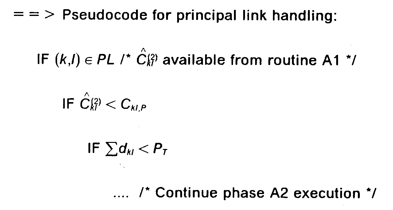
Figure 8 shows a detailed flow chart of the Modified Bellman-Ford Algorithm used to perform the accelerated search for an optimum path. Starting at 800, step 801 first sets the next node to the origin node (i). In 802, the data for the next node is retrieved from the Topology Database (306). In 803, the data for the next link leaving that node is obtained from the same Topology Database (306).Decision point 804 determines whether that link is principal or not :- · If the link is principal,
decision point 805 is entered :- ■ The accumulated loadiscomputedinstep812.:li.Then,
 is compared to the link principal threshold C kl,P :
- ▲ If the accumulated load is equal to or less than the principal threshold,the

decision point 806 tests the accumulated path length or delay. - ▲ If the accumulated load is greater than the principal threshold as determined by
decision point 805the next link is obtained in 808.
- ▲ If the accumulated load is equal to or less than the principal threshold,
- ■ The accumulated load
- · If it is determined in
decision point 804 that the link is not a principal link, the link is not considered and the next link is obtained in 808.
Indecision point 806, the accumulated path length up to this point Σd kl is compared to the maximum path length P T :- · If the accumulated path length Σd kl is less than P T , the hop count h k and the accumulated path length d kl are saved in a list (807), the node reached is also saved in order to proceed with the iteration at the next hop if necessary.
- · If the accumulated path length Σd kl is equal to or greater than P T ,
step 807 is bypassed and the data for this link is not added to the list.
In either case,decision point 808 is then entered to determine if there are any more links exiting from this node. If so,step 803 is activated to get the next link and continue the process. If there are no more links exiting from this node,decision point 809 determines if the node is the destination node (j). If so, the process is complete and terminates in 811. If this node is not the destination node (j),decision box 810 determines if there are any more nodes to be screened. If so,step 802 gets the next node and continue the process. If there are no more nodes to be screened, then the accelerated search has failed and the conventional search described in Figure 9 is started in 900.
When the procedure of Figure 8 is complete, and destination node (j) has been reached, a list of the minimum hop counts h k and the path lengths d kl is available. As discussed above, Routine B then backtracks through this list to identify the path with the minimum path delay as well as the minimum hop count. This is the optimum path to be used in sending the packets involved in the connection through the system of Figure 2.
Note : When the Modified Bellman-Ford Algorithm is used to identify the principal paths, the same flow chart as shown in Figure 10 of Patent Application 93480030.1 is used. - · If the link is principal,
- 2. Conventional Version (Routine A2)
Figure 9 shows a detailed flow chart of the Modified Bellman-Ford Algorithm used to perform the conventional search for an optimum path. Starting in 900, step 901 first sets the next node to the origin node (i). In 902, the data for the next node is retrieved from the Topology Database (306). In 903, the data for the next link leaving that node is obtained from the same Topology Database.Decision point 904 determines whether that link is principal or not :- · If the link is principal,
decision point 905 compares the accumulated loadwith the link principal threshold C kl,P This accumulated load has been computed previously during the accelerated search algorithm and so can be reused here.
- ■ If the accumulated load is equal to or less than the principal threshold,
decision point 907 tests the accumulated path delay. - ■ If the accumulated load is greater than the principal threshold, as determined by
decision point 905, the next link is obtained in 909.
- ■ If the accumulated load is equal to or less than the principal threshold,
- · If it is determined in
decision point 904 that the link is a secondary link,- ■ the accumulated loadis computed in

step 913, and - ■ then,
decision point 906 compares the accumulated loadto the link secondary threshold C kl,S .
- ▲ If the accumulated load is equal to or less than the secondary threshold, decision point tests the accumulated path delay.
- ▲ If the accumulated load is greater than the secondary threshold, as determined by
decision point 906, the next link is obtained in 909.
 In
In
decision point 907, the accumulated path length up to this point is compared to the maximum path length P T . - ■ the accumulated load
- · If the accumulated path length is less than P T , the hop count h k and the accumulated path length d kl are saved in a list in
step 908. - · If the accumulated path length is equal to or greater than P T ,
step 908 is bypassed and the data for this link is not added to the list.
- · If the link is principal,
- In either case,
decision point 909 is then entered to determine if there are any more links exiting from this node. If so,step 903 gets the next link and continues the process. If there are no more links exiting from this node, decision point 910 is entered to determine if the node is the destination node (j). If so, the process is complete and terminates in 912. If this node is not the destination node (j),decision point 911 then determines if there are any more nodes to be screened. If so,step 902 gets the next node and continues the process. If there are no more nodes to be screened, then no path is feasible, the process terminates in 912.
When the procedure of Figure 9 is complete, a list of the minimum hop counts h k and the path lengths d kl is available. As discussed above, Routine B then backtracks through this list to identify the path with the minimum path delay as well as the minimum hop count. This is the optimum path to be used in sending the packets involved in the connection through the system of Figure 2. - Figure 10 shows a typical network used to illustrate the improvements provided by the present invention. It is a packet switched network comprising 33 nodes and 126 unidirectional high speed transmission links (63 trunks) of various capacity : T1 (1.5 Mbps), T3 (45 Mbps), E1 (2 Mbps), E3 (34 Mbps), OC3 , STM1 (155 Mbps)... The average connectivity is two trunks per node with a minimum of one (Oslo, Edinburgh, Dublin, San Jose, Boston, Warsaw) and a maximum of eleven (Paris). The object of the present invention is to reduce the number of links potentially explored in searching for the optimum path between a source and a destination node. In our example, the source is Los Angeles (USA) and the destination is Milano (Italy). The
Phase 1 of the route determination procedure identifies four principal paths with a minimal hop count of three : - · Los Angeles - London - Zurich - Milano
- · Los Angeles - London - Paris - Milano
- · Los Angeles - Raleigh - Nice - Milano
- · Los Angeles - New York - Paris - Milano
- · Accelerated Version
Figure 11 shows the number of links explored by the Modified Bellman-Ford Algorithm in Routine A1 object of the present invention. Only the principal links are considered to determine the path length and feasibility. In our example, the network is reduced to 10 links : Los Angeles - London, Los Angeles - Raleigh, Los Angeles - New York, Raleigh - Nice, Nice - Milano, London - Zurich, London - Paris, Paris - Milano, Zurich - Milano, New York - Paris. - · Conventional Version
Figure 12 shows the number of links explored by the Modified Bellman-Ford Algorithm used in Routine A of the theconventional Phase 2 described in European Patent Application 93480030.1. The search is not only limited to principal links but includes also secondary links. For example, Moscow can be reached in three hops. The secondary links New York - Berlin and Berlin - Moscow are visited by the algorithm in its search for the optimum path. In our case, 54 links have been explored which represents 80% of the network. - To quantify the improvement resulting from the the new Path Selection procedure compared with the original version, a simulation has been done to estimate the performances of the path selection code running under a AIX Risc System/6000 workstation (compiled with XLC). An AIX tool providing, in output, the list of all instructions executed during the program and their usage frequency has been used.
- The simulated network is the one described in Figure 10. It comprises 33 nodes and 126 unidirectional links (63 trunks). Three tests have been run, first with the specifications detailed in European Patent Application 93480030.1 and secondly with the route determination procedure object of the present invention. The results of the computations are compared in the table hereunder : the gain of performance in term of executed instructions is about 15%.
Test hops Visited links in Phase 1Executed Instructions Conventional Accelerated Gain 1 2 22 84.005 73.604 13% 2 3 54 189.331 156.955 17% 3 5 63 241.341 199.723 17% - The performance gain can reach 50 % and more especially for longer paths and also when processors with rather poor computation capability are used, for example processors without Floating-Point capability.
-
- · These results take into account the two phases of the path selection procedure :
Phase 1 remains unchanged andPhase 2 is updated in its new version according to the present invention. - · The second pass having more floating point calculation compared with the first one, the gain would be larger with a hardware platform devoid of Floating Point Unit. For example, with a 960CF Intel processor (no Floating Point Unit), the gain is estimated to 50% for a average 4 hops path.
-
- · N is the total number of nodes in the network.
- · h is the iteration index of the algorithm, equal to the hop count.
- · h x is the hop count of the minimum hop path from the source node to the destination node satisfying the path length constraint (h x = 0 if the algorithm does not find a feasible path).
- · h k is the number of hops from the source node to node (k).
- · P T is the maximum Path Length Threshold between the origin (i) and the destination (j) nodes (maximum delay tolerated by the requesting connection).
- · d kl is the length (or delay) of the link (if any) between nodes (k) and (l).

- · C kl is the effective load (or bandwidth) capability of the link between node (k) and node (l) (Load Threshold)
- ■ C kl,P is the Load Threshold L(P) of the link (kl) as principal link in the route.
- ■ C kl,S is the Load Threshold L(S) of the link (kl) as secondary link in the route.
- · kl is the Total Allocated Load T(AL) for the link between modes (k) and (l) (total load which has already been allocated for this link due to previously calculated routes).
- · Current allocated load on link (kl) :
- ■ is the allocated load not taking the requesting connection into account.

- ■ is the allocated load after the requesting connection.

- ■
- · D(l,h) is the smallest path length (delay) from the source node to the node (l) with exactly h hops (= ∞ if no such path exists).
The requested maximum path transmission delay is generally taken as Path Length Threshold (P T ). Using these parameters, a path is determined by first searching through all links to determine minimum hop count path that satisfy the maximum path length constraint P T and then backtracking to derive a list of principal links. This search is supplemented by accumulating the link delays d kl for each path. Once the destination node is reached, minimum hop count principal paths are backtracked to create a list of principal links. This principal link list is used in the second phase of the algorithm to determine the optimum path from the source to the destination node. This specific procedure for determining paths through a packet communications system will be described with reference to Figures 5, 6, 7, 8 and 9.
Claims (10)
- A network access node (300) in a packet switching communication network (200) comprising a plurality of nodes (201..208) interconnected with transmission links (209), said node including :· means for receiving and transmitting data packets (301, 302, 304),· means for storing and updating the network configuration (306),· means, in a first phase (503), for :■ identifying principal paths including minimal hop count and minimal transmission delay Σd kl between an originating node and a destination node in said network,■ identifying principal and secondary links,· means, responsive to said means for identifying principal paths and links, for determining, in a second phase (504), an optimal path between said originating and destination nodes,and characterized in that said means for determining, in said second second phase (504), an optimal path comprises :· means for determining an optimal path using only principal links (701, 704).
- A network access node (300) according to claim 1 wherein said means for determining, in said second phase, an optimal path comprises a further means
for determining an optimal path using principal and secondary links (703, 704) when the destination node is not reached (702) using only said principal links. - A network access node (300) according to claim 2 wherein :
said means for determining an optimal path on principal and secondary links, is using link utilization data previously computed on principal links by said means for determining an optimal path on said principal links. - A network access node (300) according to anyone of claims 1 to 3 comprising
means for limiting the transmission delay in said optimal path to a preselected threshold P T (505). - A network access node (300) according to anyone of claims 1 to 4 wherein
said means for determining an optimal path between said originating and destination nodes comprises a Modified Bellman-Ford algorithm (701, 703). - A method in an access node (300) for determining an optimal routing path between an originating node and a destination node in a packet switching communication network (200) comprising a plurality of nodes (201..208) interconnected with transmission links (209), said method involving the steps of :· storing and updating the network configuration (306),· in a first phase (503) :■ identifying principal paths including minimal hop count and minimal transmission delay Σd kl between said originating node and said destination node in said network,■ identifying principal and secondary links,· determining, in a second phase (504) and in response to said step of identifying principal paths and links, an optimal path between said originating and destination nodes,and characterized in that said second phase (504) for determining an optimal path comprises the step of :· determining an optimal path using only principal links (701, 704), and
- The method according to claim 6 wherein said second phase (504) for determining an optimal path comprises the further step of :
determining, when the destination node is not reached (702) using only said principal links, an optimal path using principal and secondary links (703, 704). - The method according to claim 7 wherein
said step of determining an optimal path on principal and secondary links, is using link utilization data previously computed on principal links by said step of determining an optimal path on said principal links. - A method according to anyone of claims 6 to 8 comprising :
the step of limiting the transmission delay in said optimal path to a preselected threshold P T (505). - A method according to anyone of claims 6 to 9 wherein
said step of determining an optimal path between said originating and destination nodes comprise a Modified Bellman-Ford algorithm.
Priority Applications (4)
| Application Number | Priority Date | Filing Date | Title |
|---|---|---|---|
| EP93480231A EP0660569A1 (en) | 1993-12-22 | 1993-12-22 | Method and system for improving the processing time of the path selection in a high speed packet switching network |
| CA002130394A CA2130394C (en) | 1993-12-22 | 1994-08-18 | Method and system for improving the processing time of the path selection in a high speed packet switching network |
| JP28830994A JP2648579B2 (en) | 1993-12-22 | 1994-11-22 | Method and network node for determining optimal route |
| US08/354,407 US5600638A (en) | 1993-12-22 | 1994-12-12 | Method and system for improving the processing time of the path selection in a high speed packet switching network |
Applications Claiming Priority (1)
| Application Number | Priority Date | Filing Date | Title |
|---|---|---|---|
| EP93480231A EP0660569A1 (en) | 1993-12-22 | 1993-12-22 | Method and system for improving the processing time of the path selection in a high speed packet switching network |
Publications (1)
| Publication Number | Publication Date |
|---|---|
| EP0660569A1 true EP0660569A1 (en) | 1995-06-28 |
Family
ID=8214851
Family Applications (1)
| Application Number | Title | Priority Date | Filing Date |
|---|---|---|---|
| EP93480231A Withdrawn EP0660569A1 (en) | 1993-12-22 | 1993-12-22 | Method and system for improving the processing time of the path selection in a high speed packet switching network |
Country Status (4)
| Country | Link |
|---|---|
| US (1) | US5600638A (en) |
| EP (1) | EP0660569A1 (en) |
| JP (1) | JP2648579B2 (en) |
| CA (1) | CA2130394C (en) |
Cited By (16)
| Publication number | Priority date | Publication date | Assignee | Title |
|---|---|---|---|---|
| WO1997016907A1 (en) * | 1995-10-31 | 1997-05-09 | Northern Telecom Limited | Call routing in an atm switching network |
| EP0777362A1 (en) * | 1995-11-30 | 1997-06-04 | Lucent Technologies Inc. | A method of admission control and routing of virtual circuits |
| WO1997023101A1 (en) * | 1995-12-15 | 1997-06-26 | British Telecommunications Public Limited Company | Network management system |
| GB2311687A (en) * | 1996-03-29 | 1997-10-01 | Plessey Telecomm | Intelligent routing method in a telecommunications system |
| WO1999001991A2 (en) * | 1997-06-30 | 1999-01-14 | Nokia Networks Oy | Determining bearer services in a radio access network |
| WO1999033232A2 (en) * | 1997-12-19 | 1999-07-01 | Telefonaktiebolaget Lm Ericsson (Publ) | Method of obtaining the lowest cost link in a packet switched network |
| FR2780836A1 (en) * | 1998-07-06 | 2000-01-07 | Canon Kk | System for data communication |
| EP1019843A1 (en) * | 1996-11-25 | 2000-07-19 | Etak, Inc. | Method for determining exits and entrances for a region in a network |
| GB2351206A (en) * | 1999-06-17 | 2000-12-20 | Marconi Comm Ltd | Mesh networks |
| WO2000079730A2 (en) * | 1999-06-18 | 2000-12-28 | Digital Island, Inc. | On-demand overlay routing for computer-based communication networks |
| EP1069742A2 (en) * | 1999-07-16 | 2001-01-17 | Nortel Networks Limited | Method and architecture to support multiple services in label switched networks |
| EP1133118A2 (en) * | 2000-03-10 | 2001-09-12 | Alcatel | IP/Data traffic allocating method to maintain QoS |
| EP1216540A1 (en) * | 1999-09-06 | 2002-06-26 | Alcatel | Recursive traffic distribution ip/data network model |
| US6751194B1 (en) * | 1999-05-31 | 2004-06-15 | Nec Corporation | Packet multiplexer for priority control |
| US6891797B1 (en) | 1998-07-06 | 2005-05-10 | Canon Kabushiki Kaisha | Method and device for communicating information |
| WO2020055751A1 (en) * | 2018-09-10 | 2020-03-19 | Giacomo Bernardi | A method for intelligent multi-hop overlay routing |
Families Citing this family (128)
| Publication number | Priority date | Publication date | Assignee | Title |
|---|---|---|---|---|
| US6389010B1 (en) | 1995-10-05 | 2002-05-14 | Intermec Ip Corp. | Hierarchical data collection network supporting packetized voice communications among wireless terminals and telephones |
| US5740164A (en) * | 1993-02-09 | 1998-04-14 | Teledesic Corporation | Traffic routing for satellite communication system |
| CA2132364A1 (en) * | 1994-09-19 | 1996-03-20 | Russ Freen | Multi-network management |
| EP0753979A1 (en) * | 1995-07-13 | 1997-01-15 | International Business Machines Corporation | Routing method and system for a high speed packet switching network |
| FR2737371A1 (en) * | 1995-07-26 | 1997-01-31 | Trt Telecom Radio Electr | SECURITY BY DOUBLING AT LEAST CERTAIN LOGIC CHANNELS IN A TELECOMMUNICATIONS NETWORK |
| US6144961A (en) * | 1995-08-31 | 2000-11-07 | Compuware Corporation | Method and system for non-intrusive measurement of transaction response times on a network |
| US5721820A (en) * | 1995-09-11 | 1998-02-24 | International Business Machines Corporation | System for adaptively routing data in switching network wherein source node generates routing message identifying one or more routes form switch selects |
| JPH09219702A (en) * | 1996-02-14 | 1997-08-19 | Nec Corp | Method for retrieving free route of mesh configuration |
| GB2318030B (en) * | 1996-10-04 | 2001-03-14 | Ibm | Communication system with exchange of capability information |
| US5995503A (en) * | 1996-06-12 | 1999-11-30 | Bay Networks, Inc. | Method and apparatus for providing quality of service routing in a network |
| US6400681B1 (en) * | 1996-06-20 | 2002-06-04 | Cisco Technology, Inc. | Method and system for minimizing the connection set up time in high speed packet switching networks |
| US5940396A (en) * | 1996-08-21 | 1999-08-17 | 3Com Ltd. | Method of routing in an asynchronous transfer mode network |
| JPH10126439A (en) * | 1996-10-17 | 1998-05-15 | Fujitsu Ltd | Route selection device for packet exchange communication network |
| US5893081A (en) * | 1996-11-25 | 1999-04-06 | Etak, Inc. | Using multiple levels of costs for a pathfinding computation |
| US6252856B1 (en) * | 1996-12-03 | 2001-06-26 | Nortel Networks Limited | Method and apparatus for minimizing calculations required to construct multicast trees |
| US5903559A (en) | 1996-12-20 | 1999-05-11 | Nec Usa, Inc. | Method for internet protocol switching over fast ATM cell transport |
| US7593321B2 (en) * | 1997-02-11 | 2009-09-22 | Cisco Technology, Inc. | Method and system for a local and fast non-disruptive path switching in high speed packet switching networks |
| US5978730A (en) * | 1997-02-20 | 1999-11-02 | Sony Corporation | Caching for pathfinding computation |
| US6934249B1 (en) | 1997-04-01 | 2005-08-23 | Cisco Technology, Inc. | Method and system for minimizing the connection set up time in high speed packet switching networks |
| US6097727A (en) * | 1997-04-29 | 2000-08-01 | International Business Machines Corporation | Methods, systems and computer program products for end-to-end route selection in compound wide/local area networks |
| US5974460A (en) * | 1997-06-16 | 1999-10-26 | International Business Machines Corporation | Apparatus and method for selecting an optimum telecommunications link |
| US6038600A (en) * | 1997-07-16 | 2000-03-14 | Hewlett-Packard Company | Method and system for automatic detection of bridged and repeated network device connections |
| US6246669B1 (en) | 1997-11-28 | 2001-06-12 | Cisco Technology, Inc. | Method and system for optimizing connection set-up operations in a high speed digital network |
| US6016485A (en) * | 1998-02-13 | 2000-01-18 | Etak, Inc. | System for pathfinding |
| US6208623B1 (en) | 1998-04-13 | 2001-03-27 | 3Com Corporation | Method of combining PNNI and E-IISP in an asynchronous transfer mode network |
| US6639897B1 (en) * | 1998-04-22 | 2003-10-28 | Nippon Telegraph And Telephone Corporation | Communication network of linked nodes for selecting the shortest available route |
| US6331986B1 (en) * | 1998-04-24 | 2001-12-18 | Lucent Technologies Inc. | Method for resource allocation and routing in multi-service virtual private networks |
| US6396842B1 (en) | 1998-04-30 | 2002-05-28 | 3Com Corporation | Method of searching using longest match based Randix Search Trie with variable length keys and having prefix capability |
| US6192043B1 (en) | 1998-05-01 | 2001-02-20 | 3Com Corporation | Method of caching routes in asynchronous transfer mode PNNI networks |
| US6212188B1 (en) | 1998-05-01 | 2001-04-03 | 3Com Corporation | Method of source routing in an asynchronous transfer mode network when a node is in an overload state |
| US6262984B1 (en) | 1998-05-12 | 2001-07-17 | 3Com Corporation | Method of preventing overlapping branches in point to multipoint calls in PNNI networks |
| US6205146B1 (en) | 1998-05-28 | 2001-03-20 | 3Com Corporation | Method of dynamically routing to a well known address in a network |
| US6574669B1 (en) * | 1998-08-31 | 2003-06-03 | Nortel Networks Limited | Method and apparatus for routing traffic within a network utilizing linear optimization |
| US6147971A (en) * | 1998-11-18 | 2000-11-14 | 3Com Corporation | Optimized routing method based on minimal hop count for use in PNNI based asynchronous transfer mode networks |
| US6993027B1 (en) * | 1999-03-17 | 2006-01-31 | Broadcom Corporation | Method for sending a switch indicator to avoid out-of-ordering of frames in a network switch |
| US6195553B1 (en) | 1999-04-20 | 2001-02-27 | Analytical Graphics, Inc. | Method and apparatus for determining optimal paths among objects of a communications network |
| US6456600B1 (en) | 1999-04-28 | 2002-09-24 | 3Com Corporation | Complex node representation in an asynchronous transfer mode PNNI network |
| US6483808B1 (en) | 1999-04-28 | 2002-11-19 | 3Com Corporation | Method of optimizing routing decisions over multiple parameters utilizing fuzzy logic |
| US6594235B1 (en) | 1999-04-28 | 2003-07-15 | 3Com Corporation | Method of triggering reroutes in an asynchronous transfer mode network |
| US6577653B1 (en) | 1999-04-28 | 2003-06-10 | 3Com Corporation | Apparatus for and method of establishing a route utilizing multiple parallel segments in an asynchronous transfer mode network |
| US6473408B1 (en) | 1999-05-19 | 2002-10-29 | 3Com Corporation | Building a hierarchy in an asynchronous transfer mode PNNI network utilizing proxy SVCC-based RCC entities |
| US6614792B1 (en) | 1999-05-27 | 2003-09-02 | 3Com Corporation | Proxy MPC for providing MPOA services to legacy lane clients in an asynchronous transfer mode network |
| US6744768B2 (en) * | 1999-07-14 | 2004-06-01 | Telefonaktiebolaget Lm Ericsson | Combining narrowband applications with broadband transport |
| US6816479B1 (en) * | 1999-10-21 | 2004-11-09 | International Business Machines Corporation | Method and system for pre-loading in an NBBS network the local directory database of network nodes with the location of the more frequently requested resources |
| US6628670B1 (en) * | 1999-10-29 | 2003-09-30 | International Business Machines Corporation | Method and system for sharing reserved bandwidth between several dependent connections in high speed packet switching networks |
| US6678241B1 (en) | 1999-11-30 | 2004-01-13 | Cisc Technology, Inc. | Fast convergence with topology switching |
| US6842425B1 (en) * | 2000-02-14 | 2005-01-11 | Lucent Technologies Inc. | Method and apparatus for optimizing routing through network nodes |
| US6762997B1 (en) * | 2000-03-29 | 2004-07-13 | Lucent Technologies Inc. | Method for finding shortest network routing paths subject to system constraints |
| US6961318B2 (en) * | 2000-05-12 | 2005-11-01 | International Business Machines Corporation | Data transmission system for reserving a virtual connection over multiple IP networks by means of a reservation |
| US7366690B1 (en) * | 2000-06-23 | 2008-04-29 | Ebs Group Limited | Architecture for anonymous trading system |
| US7283477B1 (en) * | 2000-08-24 | 2007-10-16 | Nortel Networks Limited | Allocating network resources |
| US6963927B1 (en) * | 2000-08-29 | 2005-11-08 | Lucent Technologies Inc. | Method and apparatus for computing the shortest path between nodes based on the bandwidth utilization link level |
| US6965563B1 (en) * | 2000-09-28 | 2005-11-15 | Western Digital Ventures, Inc. | Resource reservation system in a computer network to support end-to-end quality-of-service constraints |
| US7509403B1 (en) * | 2000-09-28 | 2009-03-24 | Alcatel-Lucent Usa Inc. | Method and apparatus for SONET/SDH ring load balancing |
| US7403482B2 (en) | 2000-10-30 | 2008-07-22 | Nec Corporation | Path provisioning for service level agreements in differentiated service networks |
| US7319700B1 (en) * | 2000-12-29 | 2008-01-15 | Juniper Networks, Inc. | Communicating constraint information for determining a path subject to such constraints |
| EP1239635A1 (en) * | 2001-03-07 | 2002-09-11 | BRITISH TELECOMMUNICATIONS public limited company | Method of providing service classes in a packet network |
| EP1251669A1 (en) * | 2001-04-19 | 2002-10-23 | BRITISH TELECOMMUNICATIONS public limited company | Communications network |
| US7450578B2 (en) * | 2001-06-01 | 2008-11-11 | Fujitsu Limited | Method of addressing and routing data |
| US20030046378A1 (en) * | 2001-07-14 | 2003-03-06 | Zimmel Sheri L. | Apparatus and method for existing network configuration |
| KR20030039428A (en) * | 2001-11-13 | 2003-05-22 | 학교법인대우학원 | Packet Delay-based Adaptive Routing Method in the Application Layer |
| EP1335535A1 (en) * | 2002-01-31 | 2003-08-13 | BRITISH TELECOMMUNICATIONS public limited company | Network service selection |
| JP3977157B2 (en) * | 2002-06-17 | 2007-09-19 | Kddi株式会社 | Route control method and apparatus, and computer program |
| US7391732B1 (en) * | 2002-08-05 | 2008-06-24 | At&T Corp. | Scheme for randomized selection of equal cost links during restoration |
| US7225258B2 (en) * | 2002-09-09 | 2007-05-29 | General Dynamics Corporation | System and method for connecting dynamic networks with limited resources |
| US7260064B2 (en) * | 2002-10-11 | 2007-08-21 | Lucent Technologies Inc. | Method and apparatus for performing network routing based on queue lengths |
| US7280482B2 (en) * | 2002-11-01 | 2007-10-09 | Nokia Corporation | Dynamic load distribution using local state information |
| US8098637B1 (en) * | 2003-03-28 | 2012-01-17 | Regents Of The University Of Minnesota | Load balancing in wireless local area networks |
| US7394760B1 (en) * | 2003-07-09 | 2008-07-01 | Sprint Communications Company L.P. | Method and system for correlating practical constraints in a network |
| US7453824B1 (en) * | 2003-07-10 | 2008-11-18 | Sprint Communications Company L.P. | Method and system for identifying optimal mapping in a network |
| US7112105B2 (en) * | 2003-07-22 | 2006-09-26 | Hon Hai Precision Ind. Co., Ltd. | Cable assembly having power contacts |
| US7720993B2 (en) * | 2003-12-17 | 2010-05-18 | Palo Alto Research Center Incorporated | Information driven routing in ad hoc sensor networks |
| US7392482B2 (en) | 2003-12-18 | 2008-06-24 | International Business Machines Corporation | Selection accelerator in topology views |
| US8156175B2 (en) | 2004-01-23 | 2012-04-10 | Tiversa Inc. | System and method for searching for specific types of people or information on a peer-to-peer network |
| US7761569B2 (en) * | 2004-01-23 | 2010-07-20 | Tiversa, Inc. | Method for monitoring and providing information over a peer to peer network |
| US7539176B1 (en) * | 2004-04-02 | 2009-05-26 | Cisco Technology Inc. | System and method for providing link, node and PG policy based routing in PNNI based ATM networks |
| US7990846B2 (en) * | 2004-12-30 | 2011-08-02 | Alcatel-Lucent Usa Inc. | Method and apparatus for provisioning a hop limited protection pathway in a network |
| US7814227B2 (en) * | 2005-03-04 | 2010-10-12 | Cisco Technology, Inc. | Computation of a shortest inter-domain TE-LSP across a set of autonomous systems |
| US8134928B1 (en) | 2005-12-15 | 2012-03-13 | Nvidia Corporation | Technique for identifying a failed network interface card within a team of network interface cards |
| US8300798B1 (en) | 2006-04-03 | 2012-10-30 | Wai Wu | Intelligent communication routing system and method |
| CA2623805A1 (en) * | 2007-03-02 | 2008-09-02 | Robert A. Hubbs | Quality of service based preemptive routing |
| US7792018B2 (en) * | 2007-05-18 | 2010-09-07 | Nvidia Corporation | Intelligent load balancing and failover of network traffic |
| US8300647B2 (en) * | 2007-05-18 | 2012-10-30 | Nvidia Corporation | Intelligent load balancing and failover of network traffic |
| US8432788B2 (en) * | 2007-05-18 | 2013-04-30 | Nvidia Corporation | Intelligent failback in a load-balanced networking environment |
| US7995465B2 (en) * | 2007-05-18 | 2011-08-09 | Nvidia Corporation | Intelligent load balancing and failover of network traffic |
| US7756012B2 (en) * | 2007-05-18 | 2010-07-13 | Nvidia Corporation | Intelligent failover in a load-balanced network environment |
| US7760619B2 (en) * | 2007-05-18 | 2010-07-20 | Nvidia Corporation | Intelligent failover in a load-balanced networking environment |
| JP5539863B2 (en) * | 2007-06-11 | 2014-07-02 | タイヴァーサ・インコーポレーテッド | System and method for advertising on a P2P network |
| US7860100B2 (en) * | 2008-10-01 | 2010-12-28 | Cisco Technology, Inc. | Service path selection in a service network |
| US8442043B2 (en) * | 2008-12-29 | 2013-05-14 | Cisco Technology, Inc. | Service selection mechanism in service insertion architecture data plane |
| TWI398782B (en) * | 2009-07-10 | 2013-06-11 | Univ Nat Taiwan Science Tech | System reliability evaluation method for transmission by two minimal paths in time restriction |
| US8095684B2 (en) * | 2009-09-15 | 2012-01-10 | Symantec Corporation | Intelligent device and media server selection for optimized backup image duplication |
| US8780896B2 (en) | 2010-12-29 | 2014-07-15 | Juniper Networks, Inc. | Methods and apparatus for validation of equal cost multi path (ECMP) paths in a switch fabric system |
| US8798077B2 (en) | 2010-12-29 | 2014-08-05 | Juniper Networks, Inc. | Methods and apparatus for standard protocol validation mechanisms deployed over a switch fabric system |
| US8743885B2 (en) | 2011-05-03 | 2014-06-03 | Cisco Technology, Inc. | Mobile service routing in a network environment |
| US9794379B2 (en) | 2013-04-26 | 2017-10-17 | Cisco Technology, Inc. | High-efficiency service chaining with agentless service nodes |
| US9479443B2 (en) | 2014-05-16 | 2016-10-25 | Cisco Technology, Inc. | System and method for transporting information to services in a network environment |
| US9379931B2 (en) | 2014-05-16 | 2016-06-28 | Cisco Technology, Inc. | System and method for transporting information to services in a network environment |
| US10417025B2 (en) | 2014-11-18 | 2019-09-17 | Cisco Technology, Inc. | System and method to chain distributed applications in a network environment |
| USRE48131E1 (en) | 2014-12-11 | 2020-07-28 | Cisco Technology, Inc. | Metadata augmentation in a service function chain |
| US9660909B2 (en) | 2014-12-11 | 2017-05-23 | Cisco Technology, Inc. | Network service header metadata for load balancing |
| US9762402B2 (en) | 2015-05-20 | 2017-09-12 | Cisco Technology, Inc. | System and method to facilitate the assignment of service functions for service chains in a network environment |
| JP6547575B2 (en) * | 2015-10-15 | 2019-07-24 | 富士通株式会社 | Route search apparatus and route search method |
| US10084756B2 (en) * | 2015-12-30 | 2018-09-25 | Argela Yazilim ve Bilisim Teknolojileri San. ve Tic. A.S. | Anonymous communications in software-defined networks via route hopping and IP address randomization |
| US11044203B2 (en) | 2016-01-19 | 2021-06-22 | Cisco Technology, Inc. | System and method for hosting mobile packet core and value-added services using a software defined network and service chains |
| US10187306B2 (en) | 2016-03-24 | 2019-01-22 | Cisco Technology, Inc. | System and method for improved service chaining |
| US10931793B2 (en) | 2016-04-26 | 2021-02-23 | Cisco Technology, Inc. | System and method for automated rendering of service chaining |
| US10419550B2 (en) | 2016-07-06 | 2019-09-17 | Cisco Technology, Inc. | Automatic service function validation in a virtual network environment |
| US10218616B2 (en) | 2016-07-21 | 2019-02-26 | Cisco Technology, Inc. | Link selection for communication with a service function cluster |
| US10320664B2 (en) | 2016-07-21 | 2019-06-11 | Cisco Technology, Inc. | Cloud overlay for operations administration and management |
| US10225270B2 (en) | 2016-08-02 | 2019-03-05 | Cisco Technology, Inc. | Steering of cloned traffic in a service function chain |
| US10218593B2 (en) | 2016-08-23 | 2019-02-26 | Cisco Technology, Inc. | Identifying sources of packet drops in a service function chain environment |
| US10361969B2 (en) | 2016-08-30 | 2019-07-23 | Cisco Technology, Inc. | System and method for managing chained services in a network environment |
| US10225187B2 (en) | 2017-03-22 | 2019-03-05 | Cisco Technology, Inc. | System and method for providing a bit indexed service chain |
| US10178646B2 (en) | 2017-04-12 | 2019-01-08 | Cisco Technology, Inc. | System and method to facilitate slice management in a network environment |
| US10884807B2 (en) | 2017-04-12 | 2021-01-05 | Cisco Technology, Inc. | Serverless computing and task scheduling |
| US10257033B2 (en) | 2017-04-12 | 2019-04-09 | Cisco Technology, Inc. | Virtualized network functions and service chaining in serverless computing infrastructure |
| US10333855B2 (en) | 2017-04-19 | 2019-06-25 | Cisco Technology, Inc. | Latency reduction in service function paths |
| US10554689B2 (en) | 2017-04-28 | 2020-02-04 | Cisco Technology, Inc. | Secure communication session resumption in a service function chain |
| US10735275B2 (en) | 2017-06-16 | 2020-08-04 | Cisco Technology, Inc. | Releasing and retaining resources for use in a NFV environment |
| US10798187B2 (en) | 2017-06-19 | 2020-10-06 | Cisco Technology, Inc. | Secure service chaining |
| US10397271B2 (en) | 2017-07-11 | 2019-08-27 | Cisco Technology, Inc. | Distributed denial of service mitigation for web conferencing |
| US10673698B2 (en) | 2017-07-21 | 2020-06-02 | Cisco Technology, Inc. | Service function chain optimization using live testing |
| US11063856B2 (en) | 2017-08-24 | 2021-07-13 | Cisco Technology, Inc. | Virtual network function monitoring in a network function virtualization deployment |
| US10791065B2 (en) | 2017-09-19 | 2020-09-29 | Cisco Technology, Inc. | Systems and methods for providing container attributes as part of OAM techniques |
| US11018981B2 (en) | 2017-10-13 | 2021-05-25 | Cisco Technology, Inc. | System and method for replication container performance and policy validation using real time network traffic |
| US10541893B2 (en) | 2017-10-25 | 2020-01-21 | Cisco Technology, Inc. | System and method for obtaining micro-service telemetry data |
| US10666612B2 (en) | 2018-06-06 | 2020-05-26 | Cisco Technology, Inc. | Service chains for inter-cloud traffic |
Citations (1)
| Publication number | Priority date | Publication date | Assignee | Title |
|---|---|---|---|---|
| EP0568477A2 (en) * | 1992-04-28 | 1993-11-03 | International Business Machines Corporation | Method and apparatus for optinum path selection in packet transmission networks |
Family Cites Families (5)
| Publication number | Priority date | Publication date | Assignee | Title |
|---|---|---|---|---|
| US4905233A (en) * | 1987-11-23 | 1990-02-27 | Harris Corporation | Multiple path routing mechanism for packet communications network |
| GB8911395D0 (en) * | 1989-05-18 | 1989-07-05 | British Telecomm | Data communications network |
| JPH04167845A (en) * | 1990-10-31 | 1992-06-15 | Fujitsu Ltd | Data transfer system between nodes |
| US5347511A (en) * | 1993-06-07 | 1994-09-13 | International Business Machines Corp. | Traffic management in packet communications networks |
| US5317566A (en) * | 1993-08-18 | 1994-05-31 | Ascom Timeplex Trading Ag | Least cost route selection in distributed digital communication networks |
-
1993
- 1993-12-22 EP EP93480231A patent/EP0660569A1/en not_active Withdrawn
-
1994
- 1994-08-18 CA CA002130394A patent/CA2130394C/en not_active Expired - Fee Related
- 1994-11-22 JP JP28830994A patent/JP2648579B2/en not_active Expired - Lifetime
- 1994-12-12 US US08/354,407 patent/US5600638A/en not_active Expired - Lifetime
Patent Citations (1)
| Publication number | Priority date | Publication date | Assignee | Title |
|---|---|---|---|---|
| EP0568477A2 (en) * | 1992-04-28 | 1993-11-03 | International Business Machines Corporation | Method and apparatus for optinum path selection in packet transmission networks |
Non-Patent Citations (1)
| Title |
|---|
| J.S. MEDITCH ET AL.: "MINIMUM FLOW HOP ASSIGNEMT AND ROUTING SUBJECT TO AND AVERAGE MESSAGE DELAY CONSTRAINT", COMPUTERS AND ELECTRICAL ENGINEERING, vol. 10, no. 10, 1983, USA, pages 183 - 190 * |
Cited By (40)
| Publication number | Priority date | Publication date | Assignee | Title |
|---|---|---|---|---|
| WO1997016907A1 (en) * | 1995-10-31 | 1997-05-09 | Northern Telecom Limited | Call routing in an atm switching network |
| US6175870B1 (en) | 1995-11-30 | 2001-01-16 | Lucent Technologies Inc. | Method of admission control and routing of virtual circuits |
| EP0777362A1 (en) * | 1995-11-30 | 1997-06-04 | Lucent Technologies Inc. | A method of admission control and routing of virtual circuits |
| EP1235461A2 (en) * | 1995-11-30 | 2002-08-28 | Lucent Technologies Inc. | A method of admission control and routing of virtual circuits |
| EP1235461A3 (en) * | 1995-11-30 | 2004-01-02 | Lucent Technologies Inc. | A method of admission control and routing of virtual circuits |
| US6339587B1 (en) | 1995-12-15 | 2002-01-15 | British Telecommunications Plc | Network management system |
| AU704404B2 (en) * | 1995-12-15 | 1999-04-22 | British Telecommunications Public Limited Company | Network management system |
| WO1997023101A1 (en) * | 1995-12-15 | 1997-06-26 | British Telecommunications Public Limited Company | Network management system |
| GB2311687A (en) * | 1996-03-29 | 1997-10-01 | Plessey Telecomm | Intelligent routing method in a telecommunications system |
| GB2311687B (en) * | 1996-03-29 | 2000-03-08 | Plessey Telecomm | Routing and bandwidth allocation |
| EP1019843A4 (en) * | 1996-11-25 | 2003-03-19 | Tele Atlas North America Inc | Method for determining exits and entrances for a region in a network |
| EP1019843A1 (en) * | 1996-11-25 | 2000-07-19 | Etak, Inc. | Method for determining exits and entrances for a region in a network |
| WO1999001991A3 (en) * | 1997-06-30 | 1999-03-25 | Nokia Telecommunications Oy | Determining bearer services in a radio access network |
| WO1999001991A2 (en) * | 1997-06-30 | 1999-01-14 | Nokia Networks Oy | Determining bearer services in a radio access network |
| US6674733B1 (en) | 1997-06-30 | 2004-01-06 | Nokia Corporation | Determining bearer services in a radio access network |
| US6606303B1 (en) | 1997-12-19 | 2003-08-12 | Telefonaktiebolaget Lm Ericsson (Publ) | Method and device in a packet switched network |
| WO1999033232A3 (en) * | 1997-12-19 | 1999-09-02 | Ericsson Telefon Ab L M | Method of obtaining the lowest cost link in a packet switched network |
| WO1999033232A2 (en) * | 1997-12-19 | 1999-07-01 | Telefonaktiebolaget Lm Ericsson (Publ) | Method of obtaining the lowest cost link in a packet switched network |
| US7602708B2 (en) | 1998-07-06 | 2009-10-13 | Canon Kabushiki Kaisha | Method and device for communicating information |
| US6891797B1 (en) | 1998-07-06 | 2005-05-10 | Canon Kabushiki Kaisha | Method and device for communicating information |
| FR2780836A1 (en) * | 1998-07-06 | 2000-01-07 | Canon Kk | System for data communication |
| US6751194B1 (en) * | 1999-05-31 | 2004-06-15 | Nec Corporation | Packet multiplexer for priority control |
| GB2351206A (en) * | 1999-06-17 | 2000-12-20 | Marconi Comm Ltd | Mesh networks |
| GB2351206B (en) * | 1999-06-17 | 2003-12-03 | Marconi Comm Ltd | Mesh networks |
| US6778502B2 (en) | 1999-06-18 | 2004-08-17 | Savvis, Inc. | On-demand overlay routing for computer-based communication networks |
| WO2000079730A2 (en) * | 1999-06-18 | 2000-12-28 | Digital Island, Inc. | On-demand overlay routing for computer-based communication networks |
| US6473405B2 (en) | 1999-06-18 | 2002-10-29 | Digital Island, Inc. | On-demand overlay routing for computer-based communication networks |
| US8599697B2 (en) | 1999-06-18 | 2013-12-03 | Level 3 Communications, Llc | Overlay network |
| US7953888B2 (en) | 1999-06-18 | 2011-05-31 | Level 3 Communications, Llc | On-demand overlay routing for computer-based communication networks |
| EP1898571A3 (en) * | 1999-06-18 | 2010-09-01 | Level 3 CDN International, Inc. | On-demand overlay routing for computer-based communication networks |
| WO2000079730A3 (en) * | 1999-06-18 | 2001-07-12 | Digital Island Inc | On-demand overlay routing for computer-based communication networks |
| EP1069742A3 (en) * | 1999-07-16 | 2003-09-24 | Nortel Networks Limited | Method and architecture to support multiple services in label switched networks |
| US6882643B1 (en) | 1999-07-16 | 2005-04-19 | Nortel Networks Limited | Supporting multiple services in label switched networks |
| EP1069742A2 (en) * | 1999-07-16 | 2001-01-17 | Nortel Networks Limited | Method and architecture to support multiple services in label switched networks |
| EP1216540A4 (en) * | 1999-09-06 | 2005-01-05 | Cit Alcatel | Recursive traffic distribution ip/data network model |
| EP1216540A1 (en) * | 1999-09-06 | 2002-06-26 | Alcatel | Recursive traffic distribution ip/data network model |
| EP1133118A2 (en) * | 2000-03-10 | 2001-09-12 | Alcatel | IP/Data traffic allocating method to maintain QoS |
| EP1133118A3 (en) * | 2000-03-10 | 2002-02-06 | Alcatel | IP/Data traffic allocating method to maintain QoS |
| WO2020055751A1 (en) * | 2018-09-10 | 2020-03-19 | Giacomo Bernardi | A method for intelligent multi-hop overlay routing |
| US10666548B2 (en) | 2018-09-10 | 2020-05-26 | Extreme Networks, Inc. | Method for intelligent multi-hop overlay routing |
Also Published As
| Publication number | Publication date |
|---|---|
| JPH07212397A (en) | 1995-08-11 |
| CA2130394A1 (en) | 1995-06-23 |
| JP2648579B2 (en) | 1997-09-03 |
| CA2130394C (en) | 1999-01-26 |
| US5600638A (en) | 1997-02-04 |
Similar Documents
| Publication | Publication Date | Title |
|---|---|---|
| US5600638A (en) | Method and system for improving the processing time of the path selection in a high speed packet switching network | |
| US5233604A (en) | Methods and apparatus for optimum path selection in packet transmission networks | |
| US5347511A (en) | Traffic management in packet communications networks | |
| US5289462A (en) | Traffic management in packet communications networks | |
| US5402478A (en) | System and method for call-by-call source routing with rule-based fallbacks | |
| US5940372A (en) | Method and system for selecting path according to reserved and not reserved connections in a high speed packet switching network | |
| US5495479A (en) | Method and apparatus for an automatic decomposition of a network topology into a backbone and subareas | |
| US6310881B1 (en) | Method and apparatus for network control | |
| AU686048B2 (en) | Use of multipoint connection services to establish call-tapping points in a switched network | |
| US5491690A (en) | Method and apparatus to speed up the path selection in a packet switching network | |
| US6400681B1 (en) | Method and system for minimizing the connection set up time in high speed packet switching networks | |
| JP3159927B2 (en) | Network operation method, request path method, and routing and admission control method | |
| US6934249B1 (en) | Method and system for minimizing the connection set up time in high speed packet switching networks | |
| US5881050A (en) | Method and system for non-disruptively assigning link bandwidth to a user in a high speed digital network | |
| US7324552B1 (en) | Method and system for sharing reserved bandwidth between several dependent connections in high speed packet switching networks | |
| US6038212A (en) | Method and system for optimizing the connection set up time in high speed communication networks for recovering from network failure | |
| EP0714192A1 (en) | Method for preempting connections in high speed packet switching networks | |
| EP0635958A2 (en) | Design and managing method for communication networks | |
| US20060018256A1 (en) | Method and apparatus for communications traffic engineering | |
| US6628670B1 (en) | Method and system for sharing reserved bandwidth between several dependent connections in high speed packet switching networks | |
| US6683852B2 (en) | Call admission control methods and apparatus for improving route selection in packet networks | |
| EP0814583A2 (en) | Method and system for minimizing the connection set up time in high speed packet switching networks | |
| US11528085B2 (en) | Fault tolerance method for any set of simultaneous link faults in dynamic WDM optical networks with wavelength continuity constraint | |
| JPH04168835A (en) | Routing system for atm exchange and routing system for atm exchange network | |
| Balakrishnan et al. | An analysis of the timing of traffic restoration in wide area communication networks |
Legal Events
| Date | Code | Title | Description |
|---|---|---|---|
| PUAI | Public reference made under article 153(3) epc to a published international application that has entered the european phase |
Free format text: ORIGINAL CODE: 0009012 |
|
| AK | Designated contracting states |
Kind code of ref document: A1 Designated state(s): DE FR GB |
|
| 17P | Request for examination filed |
Effective date: 19951024 |
|
| STAA | Information on the status of an ep patent application or granted ep patent |
Free format text: STATUS: THE APPLICATION HAS BEEN WITHDRAWN |
|
| 18W | Application withdrawn |
Withdrawal date: 19961028 |