EP0658352A1 - Procedure for determining a parameter indicating the progress of an extracorporeal blood treatment - Google Patents
Procedure for determining a parameter indicating the progress of an extracorporeal blood treatment Download PDFInfo
- Publication number
- EP0658352A1 EP0658352A1 EP94420340A EP94420340A EP0658352A1 EP 0658352 A1 EP0658352 A1 EP 0658352A1 EP 94420340 A EP94420340 A EP 94420340A EP 94420340 A EP94420340 A EP 94420340A EP 0658352 A1 EP0658352 A1 EP 0658352A1
- Authority
- EP
- European Patent Office
- Prior art keywords
- liquid
- characteristic
- exchanger
- value
- treatment
- Prior art date
- Legal status (The legal status is an assumption and is not a legal conclusion. Google has not performed a legal analysis and makes no representation as to the accuracy of the status listed.)
- Granted
Links
Images

Classifications
-
- A—HUMAN NECESSITIES
- A61—MEDICAL OR VETERINARY SCIENCE; HYGIENE
- A61M—DEVICES FOR INTRODUCING MEDIA INTO, OR ONTO, THE BODY; DEVICES FOR TRANSDUCING BODY MEDIA OR FOR TAKING MEDIA FROM THE BODY; DEVICES FOR PRODUCING OR ENDING SLEEP OR STUPOR
- A61M1/00—Suction or pumping devices for medical purposes; Devices for carrying-off, for treatment of, or for carrying-over, body-liquids; Drainage systems
- A61M1/14—Dialysis systems; Artificial kidneys; Blood oxygenators ; Reciprocating systems for treatment of body fluids, e.g. single needle systems for hemofiltration or pheresis
- A61M1/16—Dialysis systems; Artificial kidneys; Blood oxygenators ; Reciprocating systems for treatment of body fluids, e.g. single needle systems for hemofiltration or pheresis with membranes
- A61M1/1601—Control or regulation
- A61M1/1603—Regulation parameters
- A61M1/1605—Physical characteristics of the dialysate fluid
- A61M1/1607—Physical characteristics of the dialysate fluid before use, i.e. upstream of dialyser
-
- A—HUMAN NECESSITIES
- A61—MEDICAL OR VETERINARY SCIENCE; HYGIENE
- A61M—DEVICES FOR INTRODUCING MEDIA INTO, OR ONTO, THE BODY; DEVICES FOR TRANSDUCING BODY MEDIA OR FOR TAKING MEDIA FROM THE BODY; DEVICES FOR PRODUCING OR ENDING SLEEP OR STUPOR
- A61M1/00—Suction or pumping devices for medical purposes; Devices for carrying-off, for treatment of, or for carrying-over, body-liquids; Drainage systems
- A61M1/14—Dialysis systems; Artificial kidneys; Blood oxygenators ; Reciprocating systems for treatment of body fluids, e.g. single needle systems for hemofiltration or pheresis
- A61M1/16—Dialysis systems; Artificial kidneys; Blood oxygenators ; Reciprocating systems for treatment of body fluids, e.g. single needle systems for hemofiltration or pheresis with membranes
- A61M1/1601—Control or regulation
- A61M1/1603—Regulation parameters
- A61M1/1605—Physical characteristics of the dialysate fluid
- A61M1/1609—Physical characteristics of the dialysate fluid after use, i.e. downstream of dialyser
-
- A—HUMAN NECESSITIES
- A61—MEDICAL OR VETERINARY SCIENCE; HYGIENE
- A61M—DEVICES FOR INTRODUCING MEDIA INTO, OR ONTO, THE BODY; DEVICES FOR TRANSDUCING BODY MEDIA OR FOR TAKING MEDIA FROM THE BODY; DEVICES FOR PRODUCING OR ENDING SLEEP OR STUPOR
- A61M1/00—Suction or pumping devices for medical purposes; Devices for carrying-off, for treatment of, or for carrying-over, body-liquids; Drainage systems
- A61M1/14—Dialysis systems; Artificial kidneys; Blood oxygenators ; Reciprocating systems for treatment of body fluids, e.g. single needle systems for hemofiltration or pheresis
- A61M1/16—Dialysis systems; Artificial kidneys; Blood oxygenators ; Reciprocating systems for treatment of body fluids, e.g. single needle systems for hemofiltration or pheresis with membranes
- A61M1/1601—Control or regulation
- A61M1/1617—Control or regulation using measurements made during a temporary variation of a characteristic of the fresh dialysis fluid
-
- A—HUMAN NECESSITIES
- A61—MEDICAL OR VETERINARY SCIENCE; HYGIENE
- A61M—DEVICES FOR INTRODUCING MEDIA INTO, OR ONTO, THE BODY; DEVICES FOR TRANSDUCING BODY MEDIA OR FOR TAKING MEDIA FROM THE BODY; DEVICES FOR PRODUCING OR ENDING SLEEP OR STUPOR
- A61M2205/00—General characteristics of the apparatus
- A61M2205/33—Controlling, regulating or measuring
- A61M2205/3317—Electromagnetic, inductive or dielectric measuring means
-
- A—HUMAN NECESSITIES
- A61—MEDICAL OR VETERINARY SCIENCE; HYGIENE
- A61M—DEVICES FOR INTRODUCING MEDIA INTO, OR ONTO, THE BODY; DEVICES FOR TRANSDUCING BODY MEDIA OR FOR TAKING MEDIA FROM THE BODY; DEVICES FOR PRODUCING OR ENDING SLEEP OR STUPOR
- A61M2205/00—General characteristics of the apparatus
- A61M2205/33—Controlling, regulating or measuring
- A61M2205/3324—PH measuring means
-
- A—HUMAN NECESSITIES
- A61—MEDICAL OR VETERINARY SCIENCE; HYGIENE
- A61M—DEVICES FOR INTRODUCING MEDIA INTO, OR ONTO, THE BODY; DEVICES FOR TRANSDUCING BODY MEDIA OR FOR TAKING MEDIA FROM THE BODY; DEVICES FOR PRODUCING OR ENDING SLEEP OR STUPOR
- A61M2205/00—General characteristics of the apparatus
- A61M2205/50—General characteristics of the apparatus with microprocessors or computers
- A61M2205/52—General characteristics of the apparatus with microprocessors or computers with memories providing a history of measured variating parameters of apparatus or patient
-
- A—HUMAN NECESSITIES
- A61—MEDICAL OR VETERINARY SCIENCE; HYGIENE
- A61M—DEVICES FOR INTRODUCING MEDIA INTO, OR ONTO, THE BODY; DEVICES FOR TRANSDUCING BODY MEDIA OR FOR TAKING MEDIA FROM THE BODY; DEVICES FOR PRODUCING OR ENDING SLEEP OR STUPOR
- A61M2230/00—Measuring parameters of the user
- A61M2230/65—Impedance, e.g. conductivity, capacity
Landscapes
- Health & Medical Sciences (AREA)
- Heart & Thoracic Surgery (AREA)
- Urology & Nephrology (AREA)
- Anesthesiology (AREA)
- Vascular Medicine (AREA)
- Engineering & Computer Science (AREA)
- Emergency Medicine (AREA)
- Biomedical Technology (AREA)
- Hematology (AREA)
- Life Sciences & Earth Sciences (AREA)
- Animal Behavior & Ethology (AREA)
- General Health & Medical Sciences (AREA)
- Public Health (AREA)
- Veterinary Medicine (AREA)
- External Artificial Organs (AREA)
Abstract
Description
L'invention concerne un procédé de détermination d'un paramètre significatif du progrès d'un traitement extracorporel de sang, en particulier d'un traitement d'épuration ayant pour but de pallier l'insuffisance rénale, comme l'hémodialyse ou l'hémodiafiltration.The invention relates to a method for determining a significant parameter of the progress of an extracorporeal treatment of blood, in particular of a purification treatment intended to compensate for renal insufficiency, such as hemodialysis or hemodiafiltration. .
Pour mémoire, I'hémodialyse consiste à faire circuler, de part et d'autre de la membrane semi-perméable d'un échangeur, le sang d'un patient et un liquide de traitement sensiblement isotonique au sang, de sorte que, lors du transfert diffusif qui s'établit au travers de la membrane pour les substances ayant des concentrations différentes de part et d'autre de la membrane, les impuretés du sang (urée, créatinine, etc.) migrent du sang vers le liquide de traitement. La concentration électrolytique du liquide de traitement est aussi généralement choisie pour corriger la concentration électrolytique du sang du patient.For the record, hemodialysis consists in circulating, on either side of the semi-permeable membrane of an exchanger, the blood of a patient and a treatment liquid which is substantially isotonic with the blood, so that, during the diffusive transfer which is established through the membrane for substances with different concentrations on either side of the membrane, blood impurities (urea, creatinine, etc.) migrate from the blood to the treatment liquid. The electrolytic concentration of the treatment liquid is also generally chosen to correct the electrolytic concentration of the patient's blood.
Dans le traitement par hémodiafiltration, au transfert diffusif obtenu par dialyse s'ajoute un transfert convectif par ultrafiltration résultant d'une différence de pression positive créée entre le coté sang et le coté liquide de traitement de la membrane.In hemodiafiltration treatment, to the diffusive transfer obtained by dialysis is added a convective transfer by ultrafiltration resulting from a positive pressure difference created between the blood side and the liquid side of the membrane treatment.
Il est du plus grand intérêt de pouvoir déterminer, tout au long d'une séance de traitement, un ou plusieurs paramètres significatifs du progrès du traitement afin de pouvoir, le cas échéant, modifier les conditions du traitement telles qu'elles ont été fixées initialement en vue d'un objectif thérapeutique déterminé.It is of the greatest interest to be able to determine, throughout a treatment session, one or more significant parameters of the progress of the treatment in order to be able, if necessary, to modify the conditions of treatment as they were initially set. with a view to a specific therapeutic objective.
Les paramètres dont la connaissance permet de suivre le progrès du traitement, c'est-à-dire aussi d'apprécier l'adéquation des conditions de traitement fixées initialement à l'objectif thérapeutique, sont, en particulier, la concentration du sang en un soluté donné (sodium par exemple), ou la dialysance réelle ou la clairance réelle de l'échangeur pour tel ou tel soluté (la dialysance et la clairance représentant le rendement épuratif de l'échangeur) ou la dose de dialyse administrée après un temps t de traitement, laquelle, d'après les travaux de Sargent et Gotch, peut être assimilée au rapport sans dimension Kt/V, où K est la clairance réelle pour l'urée, t le temps de traitement écoulé, et V le volume de distribution de l'urée, c'est-à-dire le volume d'eau total du patient (Gotch FA, Sargent SA. A mechanistic analysis of the National Cooperative Dialysis Study (NCDS). Kidney int 1985 ; 28 : 526-34).The parameters whose knowledge makes it possible to follow the progress of the treatment, that is to say also to assess the adequacy of the treatment conditions initially set for the therapeutic objective, are, in particular, the concentration of blood in a given solute (sodium for example), or the real dialysance or the real clearance of the exchanger for such or such solute (the dialysance and the clearance representing the purifying efficiency of the exchanger) or the dose of dialysis administered after a time t treatment, which, according to the work of Sargent and Gotch, can be compared to the dimensionless ratio Kt / V, where K is the actual clearance for urea, t the elapsed treatment time, and V the volume of distribution urea, i.e. the patient's total water volume (Gotch FA, Sargent SA. A mechanistic analysis of the National Cooperative Dialysis Study (NCDS). Kidney int 1985; 28: 526-34) .
Ces paramètres posent tous le même problème pour leur détermination, qui est de nécessiter la connaissance précise d'une caractéristique physique ou chimique du sang, alors que cette caractéristique ne peut pas, dans la pratique, être obtenue par mesure directe sur un échantillon pour des raisons thérapeutiques, prophylactiques et pécuniaires : d'une part, il est exclu de prélever sur un patient, souvent anémié, les échantillons multiples qui seraient nécessaires pour suivre l'efficacité du traitement au cours de son déroulement ; d'autre part, compte tenu des risques liés à la manipulation d'échantillons de sang éventuellement contaminé, la tendance générale est à éviter de telles manipulations ; enfin, l'analyse d'un échantillon de sang en laboratoire est à la fois coûteuse et relativement longue, ce qui est incompatible avec l'objectif recherché.These parameters all pose the same problem for their determination, which is to require precise knowledge of a physical or chemical characteristic of blood, whereas this characteristic cannot, in practice, be obtained by direct measurement on a sample for therapeutic, prophylactic and pecuniary reasons: on the one hand, it is excluded to take from a patient, often anemic, the multiple samples that would be necessary to monitor the effectiveness of treatment during its course; on the other hand, given the risks linked to the handling of possibly contaminated blood samples, the general tendency is to avoid such manipulations; Finally, the analysis of a blood sample in the laboratory is both costly and relatively long, which is incompatible with the objective sought.
Le document EP 0 547 025 décrit un procédé pour la détermination in vivo des paramètres de l'hémodialyse ne nécessitant pas d'effectuer des mesures sur le sang. Selon ce procédé, dont la mise en oeuvre requiert des moyens pour régler la concentration ionique du liquide de dialyse et des moyens pour mesurer la concentration en sodium du liquide de dialyse ou sa conductivité, le transfert électrolytique du liquide de dialyse est mesuré à deux concentrations différentes prédéterminées du liquide de dialyse et la dialysance en est déduite.The document EP 0 547 025 describes a method for the in vivo determination of hemodialysis parameters which does not require measurements to be made on the blood. According to this method, the implementation of which requires means for adjusting the ionic concentration of the dialysis liquid and means for measuring the sodium concentration of the dialysis liquid or its conductivity, the electrolytic transfer of the dialysis liquid is measured at two concentrations different predetermined dialysis fluid and dialysance is deduced therefrom.
Ce procédé nécessite d'exposer le patient à un liquide de dialyse différant sensiblement du liquide de dialyse prescrit pendant le temps nécessaire à la stabilisation de la concentration du liquide de dialyse en aval de l'échangeur, faute de quoi la mesure porte sur un liquide de dialyse de concentration intermédiaire, et tous les calculs faits ultérieurement à partir de cette mesure sont erronés.This process requires exposing the patient to a dialysis liquid which differs significantly from the prescribed dialysis liquid for the time necessary to stabilize the concentration of dialysis liquid downstream of the exchanger, otherwise the measurement relates to a liquid. of dialysis of intermediate concentration, and all the calculations made later from this measurement are incorrect.
Un but de l'invention est de concevoir un procédé du type mentionné ci-dessus grâce auquel les paramètres représentatifs du progrès du traitement puissent être déterminés fréquemment, de façon exacte, et sans pour autant que le patient doive être durablement soumis à des conditions de traitement différentes des conditions prescrites.An object of the invention is to design a method of the type mentioned above by which the parameters representative of the progress of the treatment can be determined frequently, accurately, and without the patient having to be durably subjected to conditions of different treatment of prescribed conditions.
Pour atteindre ce but, on prévoit, selon l'invention, un procédé de détermination d'un paramètre (Cb, D, K, Kt/V) significatif du progrès d'un traitement extracorporel de sang effectué dans un appareil de traitement de sang muni de moyens pour faire circuler le sang d'un patient et un liquide de traitement de part et d'autre de la membrane semi-perméable d'un échangeur à membrane, le procédé comprenant les étapes de :
- faire circuler successivement dans l'échangeur au moins un premier (d1) et un second (d2) liquides de traitement ayant une caractéristique (Cd) liée à au moins un des paramètres significatifs du traitement (Cb, D, K, Kt/V), la valeur de la caractéristique dans le premier liquide (d1) en amont de l'échangeur étant différente de la valeur de la caractéristique (Cd) dans le second liquide (d2) en amont de l'échangeur,
- mesurer dans chacun des premier (d1) et second (d2) liquides de traitement deux valeurs (Cd1in, Cd1out ; Cd2in, Cd2out) de la caractéristique (Cd), respectivement en amont et en aval de l'échangeur, le procédé étant caractérisé en ce qu'il comprend en outre les étapes de :
- mettre en circulation un troisième (d3) liquide de traitement dans l'échangeur alors que la caractéristique (Cd) dans le second liquide (d2) n'a pas atteint une valeur stable en aval de l'échangeur, la valeur de la caractéristique (Cd) dans le troisième liquide (d3) en amont de l'échangeur étant différente de la valeur de la caractéristique (Cd) dans le second liquide (d2) en amont de l'échangeur,
- mesurer deux valeurs (Cd3in, Cd3out) de la caractéristique (Cd) dans le troisième liquide (d3) respectivement en amont et en aval de l'échangeur, et
- calculer une valeur d'un paramètre significatif du progrès du traitement (Cb, D, K, Kt/V) à partir des valeurs mesurées de la caractéristique (Cd) dans le premier (d1) le second (d2) et le troisième (d3) liquides de traitement.
- circulating successively in the exchanger at least a first (d1) and a second (d2) treatment liquids having a characteristic (Cd) linked to at least one of the significant parameters of the treatment (Cb, D, K, Kt / V) , the value of the characteristic in the first liquid (d1) upstream of the exchanger being different from the value of the characteristic (Cd) in the second liquid (d2) upstream of the exchanger,
- measure in each of the first (d1) and second (d2) treatment liquids two values (Cd1in, Cd1out; Cd2in, Cd2out) of the characteristic (Cd), respectively upstream and downstream of the exchanger, the process being characterized by what it further includes the steps of:
- putting a third treatment liquid (d3) into circulation in the exchanger while the characteristic (Cd) in the second liquid (d2) has not reached a stable value downstream of the exchanger, the value of the characteristic ( Cd) in the third liquid (d3) upstream of the exchanger being different from the value of the characteristic (Cd) in the second liquid (d2) upstream of the exchanger,
- measuring two values (Cd3in, Cd3out) of the characteristic (Cd) in the third liquid (d3) respectively upstream and downstream of the exchanger, and
- calculate a value of a significant parameter of the treatment progress (Cb, D, K, Kt / V) from the measured values of the characteristic (Cd) in the first (d1) the second (d2) and the third (d3 ) processing fluids.
A l'étape de calcul, au lieu de la valeur mesurée (Cd1in, Cd2in, Cd3in) de la caractéristique (Cd) dans le premier (d1), le second (d2) et le troisième (d3) liquides de traitement, il est possible d'utiliser des valeurs de consigne correspondantes (Cd1inREF, Cd2inREF, Cd3inREF) qui sont fournies avant le début de chaque séance de traitement à une unité de commande pilotant la préparation du liquide de traitement.In the calculation step, instead of the measured value (Cd1in, Cd2in, Cd3in) of the characteristic (Cd) in the first (d1), the second (d2) and the third (d3) treatment liquids, it is it is possible to use corresponding setpoints (Cd1in REF , Cd2in REF , Cd3in REF ) which are supplied before the start of each treatment session to a control unit controlling the preparation of the treatment liquid.
Ce procédé présente l'intérêt de permettre une détermination précise des paramètres significatifs du progrès du traitement à partir de mesures effectuées à intervalles de temps rapprochés. De la sorte, le patient n'est exposé que pendant un temps très court à un liquide de traitement différent du liquide de traitement prescrit (par exemple trop riche ou trop pauvre en sodium) et le procédé peut être mis en oeuvre aussi souvent que nécessaire pour un suivi approprié de la séance de traitement.This method has the advantage of allowing a precise determination of the significant parameters of the progress of the treatment from measurements made at close time intervals. In this way, the patient is only exposed for a very short time to a treatment liquid different from the prescribed treatment liquid (for example too rich or too low in sodium) and the method can be carried out as often as necessary. for an appropriate follow-up of the treatment session.
Selon une caractéristique de l'invention, l'intervalle de temps (t2-ta) entre l'instant (ta), où le second liquide (d2) est mis en circulation dans l'échangeur, et l'instant (t2), où la valeur (Cd2out) de la caractéristique (Cd) dans le second liquide est mesurée en aval de l'échangeur, est choisi tel que la caractéristique (Cd) n'a pas atteint une valeur stable à l'instant (t2) en aval de l'échangeur et l'intervalle de temps (t3-tb) entre l'instant (tb), où le troisième liquide (d3) est mis en circulation dans l'échangeur, et l'instant (t3), où la valeur (Cd3out) de la caractéristique (Cd) dans le troisième liquide est mesurée en aval de l'échangeur, est choisi tel que la caractéristique (Cd) n'a pas atteint une valeur stable à l'instant (t3) en aval de l'échangeur.According to a characteristic of the invention, the time interval (t2-ta) between the instant (ta), when the second liquid (d2) is put into circulation in the exchanger, and the instant (t2), where the value (Cd2out) of the characteristic (Cd) in the second liquid is measured downstream of the exchanger, is chosen such that the characteristic (Cd) has not reached a stable value at the time (t2) in downstream of the exchanger and the time interval (t3-tb) between the instant (tb), when the third liquid (d3) is circulated in the exchanger, and the instant (t3), where the value (Cd3out) of the characteristic (Cd) in the third liquid is measured downstream of the exchanger, is chosen such that the characteristic (Cd) has not reached a stable value at the time (t3) downstream of the exchanger.
Dans un mode de réalisation de l'invention, les intervalles de temps (t2-ta) et (t3-tb) sont choisis sensiblement égaux et la valeur de la caractéristique (Cd) dans le troisième liquide (d3) est choisie sensiblement égale à la valeur de la caractéristique (Cd) dans le premier liquide (d1). Le liquide de traitement prescrit peut être utilisé comme premier liquide au sens de l'invention.In one embodiment of the invention, the time intervals (t2-ta) and (t3-tb) are chosen to be substantially equal and the value of the characteristic (Cd) in the third liquid (d3) is chosen to be substantially equal to the value of the characteristic (Cd) in the first liquid (d1). The prescribed treatment liquid can be used as the first liquid within the meaning of the invention.
Selon une autre caractéristique de l'invention, le procédé comprend en outre l'étape de calculer au moins une deuxième valeur, approchée, d'un même paramètre significatif du traitement (Cb, D, K, Kt/V). Il est alors possible de comparer ces valeurs et d'émettre un signal d'erreur si elles ne vérifient pas une loi prédéfinie. Ceci permet de contrôler qu'aucun événement indésirable n'est venu perturber les conditions de la mesure. Comme exemple de perturbation, on peut mentionner l'augmentation du débit de recirculation du sang dans le système de traitement, qui peut résulter d'un mouvement du patient, ou encore l'injection d'un liquide dans le circuit extracorporel de sang connectant le patient à l'échangeur.According to another characteristic of the invention, the method further comprises the step of calculating at least a second, approximate value, of the same significant parameter of the processing (Cb, D, K, Kt / V). It is then possible to compare these values and to issue an error signal if they do not verify a predefined law. This makes it possible to check that no undesirable event has come to disturb the conditions of the measurement. As an example of disturbance, we can mention the increase in the rate of recirculation of blood in the treatment system, which can result from a movement of the patient, or the injection of a liquid in the extracorporeal circuit of blood connecting the patient at the exchanger.
D'autres caractéristiques et avantages de l'invention apparaîtront à la lecture de la description qui suit. On se reportera aux dessins sur lesquels :
- La figure 1 est une représentation schématique partielle d'une installation d'hémodialyse/hémodiafiltration adaptée à la mise en oeuvre du procédé selon l'invention ; et
- La figure 2 est un diagramme représentant l'évolution de la conductivité du liquide de traitement en fonction du temps lors de la mise en oeuvre du procédé selon l'invention.
- FIG. 1 is a partial schematic representation of a hemodialysis / hemodiafiltration installation suitable for implementing the method according to the invention; and
- FIG. 2 is a diagram representing the evolution of the conductivity of the treatment liquid as a function of time during the implementation of the method according to the invention.
L'installation d'hémodialyse/hémodiafiltration représentée sur la figure 1 comprend un échangeur 1, tel qu'un hémodialyseur ou un hémofiltre, ayant un premier et un second compartiments 2, 3 séparés par une membrane semi-perméable 4.The hemodialysis / hemodiafiltration installation shown in FIG. 1 comprises an
Le premier compartiment 2 est connecté à un circuit 5 pour circulation extracorporelle de sang et le second compartiment 3 est connecté à un circuit de liquide de dialyse comprenant une canalisation d'alimentation 6 reliant un générateur 7 de liquide de dialyse à une entrée du second compartiment 3 et une canalisation d'évacuation 8 reliant une sortie du second compartiment 3 à un circuit d'eaux usées.The
Une première pompe de circulation 9 est disposée sur la canalisation d'alimentation 6 et une seconde pompe 10 est disposée sur la canalisation d'évacuation 8, le débit de cette seconde pompe étant réglé par des moyens non représentés pour être égal au débit de la première pompe. Une pompe d'extraction 11 est connectée à la canalisation d'évacuation 8, en amont de la deuxième pompe 10, pour extraire du circuit de dialyse, le cas échéant, une quantité dosée de liquide usé correspondant à la quantité d'eau plasmatique qui est prélevée au patient par ultrafiltration.A first circulation pump 9 is placed on the
Le générateur 7 de liquide de dialyse comprend deux réservoirs 12, 13 pour solutions concentrées reliés à un réservoir de préparation 14 destiné au mélange dosé de deux solutions concentrées avec de l'eau. Le débit d'écoulement des solutions dans le réservoir de préparation 14 peut être réglé respectivement par deux pompes 15, 16. Les solutions concentrées, qui sont de compositions complémentaires, comprennent en combinaison les principaux électrolytes du sang (sodium, potassium, calcium, magnésium, chlorures et bicarbonates). Un dispositif de chauffage 17 et une sonde de conductivité 18 sont disposés dans le réservoir de préparation 14.The
L'installation est munie aussi d'un circuit de mesure de caractéristiques du liquide de dialyse permettant d'effectuer, pour chaque caractéristique considérée, une mesure sur le liquide de dialyse frais et une mesure sur le liquide usé au moyen d'une même sonde. A cette fin, le circuit de mesure comprend une première et une seconde lignes secondaires 19, 20 montées en dérivation à l'échangeur 1 entre la ligne d'alimentation 6 et la ligne d'évacuation 8 du circuit de liquide de dialyse, ainsi qu'une ligne de jonction 21, reliant la première à la seconde ligne secondaire, dans laquelle est disposée une cellule de mesure 22 contenant une ou plusieurs sondes de mesure de caractéristiques du liquide de dialyse. La première ligne secondaire 19 est connectée respectivement aux lignes d'alimentation 6 et d'évacuation 8 au moyen de deux vannes trois-voies 23, 24 et la ligne de jonction 21 est connectée à la seconde ligne secondaire 20 au moyen d'une vanne trois-voies 25. Selon la disposition des vannes 23, 24, 25, c'est le liquide de dialyse frais (flèches en trait continu) ou le liquide usé (flèches en trait interrompu) qui circule dans la cellule de mesure 22.The installation is also provided with a circuit for measuring characteristics of the dialysis liquid making it possible to carry out, for each characteristic considered, a measurement on the fresh dialysis liquid and a measurement on the spent liquid by means of the same probe. . To this end, the measurement circuit comprises first and second
Une unité de calcul et de commande 26 pilote le fonctionnement de l'installation en fonction de valeurs de consigne qui lui sont fournies initialement pour les paramètres du traitement, en particulier, le débit de sang, le débit du liquide de dialyse, le débit d'ultrafiltration, la température et la concentration électrolytique du liquide de dialyse, la durée de la séance de traitement. Dans le cadre spécifique de l'invention, I'unité de commande 26 déclenche, à intervalle régulier, selon une séquence prédéterminée, la prise d'une série de mesures sur le liquide de dialyse. Conformément au procédé décrit plus loin, cette phase de mesure nécessite la production successive de trois liquides de dialyse de conductivités nominales différentes par le générateur de dialyse 7, la bascule des vannes 23, 24, 25 d'une position dans l'autre pour que la cellule de mesure 22 soit irriguée, pour chacun des trois liquides de dialyse, par du liquide frais et du liquide usé, et enfin le séquencement précis des prises de mesure proprement dites.A calculation and
Dans un but de clarté, on a omis de représenter sur la figure 1 divers composants et accessoires d'une installation d'hémodialyse/hémodiafiltration dont la description n'aiderait pas à l'intelligence de l'invention, tels que, notamment, des moyens de mesure de pression dans les différents circuits et des moyens de mesure de débit Qd du liquide de dialyse et et de mesure de débit Quf d'ultrafiltration.For the sake of clarity, we have omitted to represent in FIG. 1 various components and accessories of an installation hemodialysis / hemodiafiltration, the description of which would not assist the understanding of the invention, such as, in particular, means for measuring pressure in the various circuits and means for measuring the flow rate Qd of the dialysis liquid and and of ultrafiltration flow measurement Quf.
Comme cela a été rappelé plus haut, le principe de l'invention consiste à mesurer certaines caractéristiques du liquide de traitement (liquide de dialyse) afin d'en déduire par le calcul la valeur réelle de caractéristiques correspondantes du sang, ainsi que la valeur réelle de paramètres significatifs de l'efficacité du traitement, liés à ces caractéristiques du sang.As mentioned above, the principle of the invention consists in measuring certain characteristics of the treatment liquid (dialysis liquid) in order to deduce therefrom by calculation the real value of corresponding characteristics of the blood, as well as the real value significant parameters of the effectiveness of the treatment, linked to these characteristics of the blood.
La cellule de mesure 22 peut ainsi contenir une sonde de température, une sonde de conductivité, une électrode de mesure de concentration en tel ou tel soluté, une sonde de pH et de mesure de pression partielle de CO₂, etc.The
Dans la suite on décrira le procédé selon l'invention en prenant l'exemple, qui ne saurait être considéré comme limitatif, d'une mesure de conductivité. On rappelle qu'il existe une excellente corrélation entre la conductivité du liquide de dialyse et sa concentration en substances ionisées, dont le sodium représente la part prépondérante. C'est grâce à cette corrélation qu'il est possible de calculer la concentration réelle (Cbin) en sodium du sang à l'entrée de l'échangeur à partir de quatre valeurs mesurées de la conductivité du liquide de dialyse (Cd1in, Cd2in, Cd1out, Cd2out, respectivement conductivité à l'entrée et à la sortie de l'échangeur, mesurée lors du passage successif d'un premier et d'un second liquide de dialyse d1, d2 ayant des conductivités différentes), par application de la formule :![]()
laquelle est déduite de la formule générale de la dialysance D :![]()
où Qd est le débit de liquide dans le compartiment de l'échangeur connecté au circuit de dialyse, Quf est le débit d'ultrafiltration, Cdin et Cdout la conductivité/concentration en substances ionisées du liquide de dialyse en amont et en aval de l'échangeur et Cbin, la concentration en sodium du sang en amont de l'échangeur.In the following, the method according to the invention will be described by taking the example, which cannot be considered as limiting, of a measurement of conductivity. It will be recalled that there is an excellent correlation between the conductivity of the dialysis liquid and its concentration of ionized substances, of which sodium represents the predominant part. It is thanks to this correlation that it is possible to calculate the real sodium concentration (Cbin) of blood sodium at the inlet of the exchanger from four measured values of the conductivity of the dialysis liquid (Cd1in, Cd2in, Cd1out, Cd2out, respectively conductivity at the inlet and at the outlet of the exchanger, measured during the successive passage of a first and a second dialysis liquid d1, d2 having different conductivities), by application of the formula : ![]()
which is deduced from the general formula of dialysis D: ![]()
where Qd is the flow rate of liquid in the exchanger compartment connected to the dialysis circuit, Quf is the ultrafiltration flow rate, Cdin and Cdout the conductivity / concentration of ionized substances in the dialysis liquid upstream and downstream of the exchanger and Cbin, the sodium concentration of the blood upstream of the exchanger.
Connaissant la valeur réelle de la concentration Cbin du sodium dans le sang à l'entrée de l'échangeur, on peut calculer la dialysance réelle D du système au moyen de la formule (2).Knowing the actual value of the Cbin concentration of sodium in the blood at the inlet of the exchanger, the actual dialysance D of the system can be calculated by means of formula (2).
Sachant par ailleurs qu'il existe des tables de correspondance entre la dialysance pour le sodium et la clairance pour l'urée, on peut déduire la clairance réelle K de l'échangeur pour l'urée de la dialysance réelle calculée D.Knowing moreover that there are correspondence tables between the dialysance for sodium and the clearance for urea, one can deduce the real clearance K of the exchanger for urea from the real calculated dialysance D.
Enfin, à partir de la clairance réelle K, de la durée écoulée du traitement t et du volume V de répartition de l'urée dans le patient (qui dépend du poids moyen, du sexe et de l'âge), on peut calculer la dose de dialyse administrée Kt/V.Finally, from the actual clearance K, the elapsed time of treatment t and the volume V of distribution of urea in the patient (which depends on average weight, sex and age), one can calculate the dialysis dose administered Kt / V.
Conformément à l'invention, afin d'éviter de soumettre le patient à des conditions de traitement hors de la normale (liquide de dialyse ayant une conductivité supérieure ou inférieure à la conductivité prescrite) pendant un temps significatif, on effectue trois séries de mesures de conductivité rapprochées sur trois liquides de dialyse d1, d2, d3 de conductivités nominales différentes, les mesures sur le second et le troisième liquides de dialyse d2, d3 en aval de l'échangeur étant prises avant que cette conductivité ne se soit stabilisée. La façon dont les différents paramètres significatifs de l'évolution du traitement peuvent être calculés exactement à partir de mesures prises pendant un état transitoire du liquide de dialyse pour ce qui est de la conductivité va être expliquée maintenant en relation avec la figure 2.In accordance with the invention, in order to avoid subjecting the patient to out-of-normal treatment conditions (dialysis liquid having a conductivity higher or lower than the prescribed conductivity) for a significant time, three series of measurements are carried out. close conductivity on three dialysis liquids d1, d2, d3 with different nominal conductivities, the measurements on the second and third dialysis liquids d2, d3 downstream of the exchanger being taken before this conductivity has stabilized. The way in which the various significant parameters of the evolution of the treatment can be calculated exactly from measurements taken during a transient state of the dialysis liquid as regards conductivity will now be explained in relation to FIG. 2.
La figure 2 représente deux graphes de la conductivité du liquide de dialyse en fonction du temps, le graphe 1 en trait continu correspond à l'évolution de la conductivité en amont de l'échangeur et le graphe 2 en trait interrompu correspond à l'évolution de la conductivité en aval de l'échangeur.FIG. 2 represents two graphs of the conductivity of the dialysis liquid as a function of time, the
Conformément à ces graphes, un premier liquide de dialyse d1 de conductivité constante préparé par le générateur 7 est mis en circulation dans l'échangeur 1 jusqu'à un instant ta. La conductivité du liquide de dialyse d1, en amont de l'échangeur 1, est, en principe, sensiblement égale à la valeur de consigne correspondante fournie à l'unité de commande 26 avant le début de la séance de traitement.According to these graphs, a first dialysis liquid d1 of constant conductivity prepared by the
Le liquide de dialyse d1 est de préférence celui dont la composition électrolytique a été prescrite initialement par le médecin. On remarque que la conductivité en aval du dialyseur est supérieure à la conductivité en amont, ce qui signifie qu'un transfert de substances ionisées se produit dans l'échangeur, du sang vers le liquide de dialyse. Antérieurement à l'instant ta, on mesure successivement, grâce au dispositif de mesure représenté sur la figure 1, la conductivité Cd1 in du premier liquide de dialyse en amont de l'échangeur 1, puis la conductivité Cd1 out en aval de l'échangeur, cette seconde mesure étant prise à l'instant t1. Les valeurs mesurées Cd1in et Cd1out sont mises en mémoire dans une mémoire de l'unité de commande et de calcul 26.The dialysis liquid d1 is preferably that whose electrolytic composition was initially prescribed by the doctor. It is noted that the conductivity downstream of the dialyzer is higher than the conductivity upstream, which means that a transfer of ionized substances occurs in the exchanger, from the blood to the dialysis liquid. Before the instant ta, the conductivity Cd1 in of the first dialysis liquid upstream of the
Le générateur 7 de liquide de dialyse est programmé ensuite pour produire, pendant une courte période de temps tb - ta (deux minutes par exemple), un second liquide de dialyse d2 différant du premier liquide de dialyse d1 par une conductivité nominale plus élevée, également constante. La conductivité du liquide de dialyse d2, en amont de l'échangeur 1, est, en principe, sensiblement égale à la valeur de consigne correspondante Cd2inREF fournie à l'unité de commande 26 avant le début de la séance de traitement. Ce qui circule alors dans le circuit de dialyse est pour un temps un mélange du premier et du second liquides de dialyse d1, d2, où la proportion du premier diminue graduellement, ce que traduisent les graphes par une courbe ascendante s'applatissant rapidement pour tendre vers une asymptote horizontale. On remarque que la conductivité en amont du dialyseur (graphe 1) se stabilise rapidement, avant l'instant tb, alors que la conductivité en aval de l'échangeur (graphe 2) tend plus lentement vers une valeur constante, qu'elle n'a pas atteinte à l'instant tb. Cela est dû au fait que la conductivité en aval de l'échangeur ne cesse pas d'évoluer aussi longtemps que l'échangeur n'a pas été totalement purgé du mélange résultant de la mise en circulation du second liquide de dialyse et aussi longtemps que les phénomènes de transfert diffusifs n'ont pas atteint un régime d'équilibre dans l'échangeur.The
On remarque aussi, dans la portion ascendante des graphes, que la conductivité du liquide de dialyse à l'entrée de l'échangeur est supérieure à la conductivité du liquide de dialyse à la sortie de l'échangeur, ce qui traduit le fait qu'un transfert diffusif de substances ionisées a lieu cette fois du liquide de dialyse vers le sang.We also note, in the ascending portion of the graphs, that the conductivity of the dialysis liquid at the inlet of the exchanger is higher than the conductivity of the dialysis liquid at the outlet of the exchanger, which reflects the fact that a diffusive transfer of ionized substances takes place this time from the dialysis liquid to the blood.
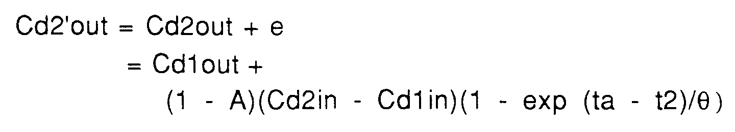
Antérieurement à l'instant tb, on mesure successivement, au moyen du dispositif de mesure représenté sur la figure 1, la conductivité Cd2in du second liquide de dialyse en amont de l'échangeur 1, puis la conductivité Cd2out en aval de l'échangeur, cette seconde mesure étant prise à l'instant t2. Il existe une différence e entre la valeur de la conductivité Cd2out mesurée en aval de l'échangeur 1 et ce qui serait la valeur exacte ou stabilisée Cd2'out de la conductivité du second liquide de dialyse d2 en aval de l'échangeur si le second liquide de dialyse d2 était mis en circulation suffisamment longtemps dans le circuit de liquide de dialyse, ce qui, pour les raisons mentionnées plus haut, est indésirable. Les valeurs mesurées Cd2in et Cd2out sont mises en mémoire dans une mémoire de l'unité de commande et de calcul 26.Prior to time tb, the conductivity Cd2in of the second dialysis liquid upstream of the
A partir de l'instant tb, le générateur de liquide de dialyse 7 est programmé pour produire un troisième liquide de dialyse d3 ayant une conductivité nominale constante inférieure à la conductivité du second liquide de dialyse d2. La conductivité du liquide de dialyse d3, en amont de l'échangeur 1, est en principe, sensiblement égale à la valeur de consigne correspondante Cd3inREF fournie à l'unité de commande 26 avant le début de la séance de traitement. Il circule alors pour un temps dans le circuit de dialyse un mélange du second et du troisième liquide de dialyse d2, d3, où la proportion du troisième liquide de dialyse d3 augmente rapidement, ce que traduisent les graphes par une courbe descendante s'applatissant pour tendre vers une asymptote horizontale correspondant à la valeur de la conductivité du troisième liquide de dialyse d3 respectivement en amont (graphe 1) et en aval (graphe 2) de l'échangeur. Pour les mêmes raisons que lors de la phase de circulation du deuxième liquide de dialyse, la conductivité en amont de l'échangeur se stabilise plus vite que la conductivité en aval de l'échangeur pour finir par atteindre la valeur de la conductivité du troisième liquide de dialyse d3. On remarque que, peu après l'instant tb il se produit un renversement du sens du transfert diffusif des substances ionisées dans l'échangeur, ces substances migrant à nouveau du sang vers le liquide de dialyse.From time tb, the
Lorsque la conductivité en amont de l'échangeur est stabilisée et alors que la conductivité en aval de l'échangeur décroît toujours, on mesure successivement la valeur de ces conductivités, respectivement Cd3in et Cd3out, la mesure de la conductivité en aval de l'échangeur étant prise à l'instant t3 et cette valeur différant de la valeur stabilisée Cd3'out (conductivité du troisième liquide de dialyse d3) d'une quantité e'. Les valeurs mesurées Cd3in et Cd3out sont sont mises en mémoire dans une mémoire de l'unité de commande et de calcul 26.When the conductivity upstream of the exchanger is stabilized and while the conductivity downstream of the exchanger always decreases, the value of these conductivities, Cd3in and Cd3out, is successively measured, the measurement of the conductivity downstream of the exchanger being taken at time t3 and this value differing from the stabilized value Cd3'out (conductivity of the third dialysis liquid d3) by an amount e '. The measured values Cd3in and Cd3out are stored in a memory of the control and
A l'issue de l'étape de prise de mesures qui vient d'être décrite, I'unité de commande et de calcul a donc en mémoire six valeurs mesurées Cd1in, Cd1out, Cd2in, Cd2out, Cd3in, Cd3out, qui ne sont pas directement exploitables par application de la formule 1, laquelle n'est exacte que pour les valeurs de conductivité stabilisées.At the end of the step of taking measurements which has just been described, the control and calculation unit therefore has in memory six measured values Cd1in, Cd1out, Cd2in, Cd2out, Cd3in, Cd3out, which are not directly usable by application of
Selon l'invention, pour calculer la concentration Cbin du sang en sodium en amont de l'échangeur ou la dialysance réelle D du système, on part de l'observation que les quantités e, e' ne dépendent que de trois facteurs : l'amplitude de la perturbation (Cd2in-Cd1in, Cd3in-Cd2in) induite dans le système par la mise en circulation du second liquide de dialyse d2 et du troisième liquide de dialyse d3 ; l'instant de la mesure (t2, t3) par rapport au début de la perturbation (ta, tb) et la constante de temps ϑ du système, qui dépend des débits du liquide de dialyse et du sang, de la surface de la membrane 4 et du coefficient de diffusion de la membrane pour le soluté considéré, ici le sodium.According to the invention, to calculate the concentration Cbin of the blood in sodium upstream of the exchanger or the real dialysance D of the system, it is started from the observation that the quantities e, e 'depend only on three factors: amplitude of the disturbance (Cd2in-Cd1in, Cd3in-Cd2in) induced in the system by the circulation of the second dialysis liquid d2 and the third dialysis liquid d3; the instant of the measurement (t2, t3) relative to the start of the disturbance (ta, tb) and the time constant ϑ of the system, which depends on the flow rates of the dialysis liquid and blood, on the surface of the membrane 4 and the diffusion coefficient of the membrane for the solute considered, here sodium.
C'est ainsi qu'en choisissant deux perturbations dont les amplitudes soient égales en valeur absolue, ainsi que des intervalles de temps entre le début de chaque perturbation et la mesure correspondante qui soient égaux (t2 - ta = t3 - tb), on est assuré que les quantités e et e' sont égales, de sorte que, par application de la formule (2), le calcul de Cbin ou de D se fera simplement par la résolution de trois équations à trois inconnues, Cbin, D et e, les débits de liquide de dialyse et d'ultrafiltration Qd et Quf étant connus par ailleurs. D'autres paramètres significatifs du progrès de la séance de dialyse, tels que la clairance K ou la dose de dialyse Kt/V seront déduits immédiatement du calcul de la concentration réelle du sodium dans le sang Cbin ou de la dialysance réelle D.Thus by choosing two disturbances whose amplitudes are equal in absolute value, as well as time intervals between the start of each disturbance and the corresponding measurement which are equal (t2 - ta = t3 - tb), we are assured that the quantities e and e 'are equal, so that, by applying formula (2), the calculation of Cbin or D will be done simply by solving three equations with three unknowns, Cbin, D and e, the flow rates of dialysis liquid and of ultrafiltration Qd and Quf being known elsewhere. Other significant parameters of the progress of the dialysis session, such as the clearance K or the dose of dialysis Kt / V will be deduced immediately from the calculation of the real concentration of sodium in the blood Cbin or of the real dialysis D.
A titre d'exemple, le système d'équations mentionné plus haut peut être mis sous la forme suivante :![]()
![]()
où![]()
![]()
![]()
or ![]()
Par ailleurs, selon l'invention, on calcule plusieurs valeurs du même paramètre de façon à vérifier si une perturbation accidentelle est intervenue pendant l'étape de prise de mesures décrite plus haut. Par exemple, on peut calculer trois valeurs de la dialysance D, une première valeur exacte D0 en fonction des six mesures de conductivité, une second valeur approchée D1 en fonction de Cd1in, Cd1out, Cd2in, Cd2out et une troisième valeur approchée D2 en fonction de Cd2in, Cd2out, Cd3in, Cd3out. Ensuite, on contrôle si les trois valeurs ainsi calculées obéissent à une ou plusieurs lois prédéfinies telles que : D0 inférieur ou égal à D1 et D1 inférieur ou égal à D2, ou encore la différence D0-D1 est égale ou sensiblement égale à la différence D1-D2. Dans le cas où une de ces lois ne serait pas respectée, un signal d'erreur est émis.Furthermore, according to the invention, several values of the same parameter are calculated so as to check whether an accidental disturbance occurred during the step of taking measurements described above. For example, we can calculate three values of dialysance D, a first exact value D0 as a function of the six conductivity measurements, a second approximate value D1 as a function of Cd1in, Cd1out, Cd2in, Cd2out and a third approximate value D2 as a function of Cd2in, Cd2out, Cd3in, Cd3out. Then, it is checked whether the three values thus calculated obey one or more predefined laws such as: D0 less than or equal to D1 and D1 less than or equal to D2, or else the difference D0-D1 is equal or substantially equal to the difference D1 -D2. In the event that one of these laws is not observed, an error signal is issued.
L'invention qui vient d'être décrite est susceptible de variantes, à la fois en ce qui concerne l'étape de prise de mesures proprement dite (choix de la valeur de la conductivité nominale des différents liquides de dialyse, c'est-à-dire aussi amplitude et sens de la perturbation induite dans le système, et choix de l'instant où les mesures sont prises en fonction du début des perturbations successives) et façon dont les paramètres significatifs du déroulement du traitement sont calculés à partir des valeurs de conductivité mesurées.The invention which has just been described is susceptible of variants, both with regard to the step of taking measurements proper (choice of the value of the nominal conductivity of the various dialysis liquids, that is to say -also say amplitude and direction of the disturbance induced in the system, and choice of the moment when the measurements are taken as a function of the beginning of the successive disturbances) and how the significant parameters of the course of the treatment are calculated from the values of conductivity measured.
En ce qui concerne le choix du sens de l'échelon de conductivité entre deux liquides de dialyse mis en circulation successivement, toutes les combinaisons sont possibles. A titre d'exemple :With regard to the choice of the direction of the conductivity step between two dialysis liquids circulated successively, all combinations are possible. For exemple :
La valeur de la caractéristique Cd dans le premier liquide d1 est choisie inférieure à la valeur de la caractéristique Cd dans le second liquide d2, laquelle est elle-même choisie inférieure à la valeur de la caractéristique Cd dans le troisième liquide d3.The value of the characteristic Cd in the first liquid d1 is chosen lower than the value of the characteristic Cd in the second liquid d2, which is itself chosen lower than the value of the characteristic Cd in the third liquid d3.
La valeur de la caractéristique Cd dans le premier liquide d1 est choisie supérieure à la valeur de la caractéristique Cd dans le second liquide d2, laquelle est elle-même choisie supérieure à la valeur de la caractéristique Cd dans le troisième liquide d3.The value of the characteristic Cd in the first liquid d1 is chosen to be greater than the value of the characteristic Cd in the second liquid d2, which is itself chosen greater than the value of the characteristic Cd in the third liquid d3.
La valeur de la caractéristique Cd dans le premier liquide d1 est choisie inférieure à la valeur de la caractéristique Cd dans le second liquide d2, laquelle est elle-même choisie supérieure à la valeur de la caractéristique Cd dans le troisième liquide d3.The value of the characteristic Cd in the first liquid d1 is chosen lower than the value of the characteristic Cd in the second liquid d2, which is itself chosen greater than the value of the characteristic Cd in the third liquid d3.
La valeur de la caractéristique Cd dans le premier liquide d1 est choisie supérieure à la valeur de la caractéristique Cd dans le second liquide d2, laquelle est elle-même choisie inférieure à la valeur de la caractéristique Cd dans le troisième liquide d3.The value of the characteristic Cd in the first liquid d1 is chosen greater than the value of the characteristic Cd in the second liquid d2, which is itself chosen lower than the value of the characteristic Cd in the third liquid d3.
La valeur de la caractéristique Cd dans le second liquide d2 en amont de l'échangeur est choisie inférieure ou supérieure à la valeur de la caractéristique Cd dans le premier liquide d1 en amont de l'échangeur, en fonction du signe de la différence (Cdin1-Cdout1) entre les valeurs mesurées de la caractéristique Cd dans le premier liquide d1 en amont et en aval de l'échangeur.The value of the characteristic Cd in the second liquid d2 upstream of the exchanger is chosen to be lower or higher than the value of the characteristic Cd in the first liquid d1 upstream of the exchanger, depending on the sign of the difference (Cdin1 -Cdout1) between the measured values of the characteristic Cd in the first liquid d1 upstream and downstream of the exchanger.
La valeur de la caractéristique Cd dans le troisième liquide d3 en amont de l'échangeur est choisie inférieure ou supérieure à la valeur de la caractéristique Cd dans le second liquide d2 en amont de l'échangeur, en fonction du signe de la différence (Cdin1-Cdout1) entre les valeurs mesurées de de la caractéristique Cd dans le premier liquide d1 en amont et en aval de l'échangeur et/ou en fonction du signe de la différence (Cdin2-Cdout2) entre les valeurs mesurées de de la caractéristique Cd dans le second liquide d2 en amont et en aval de l'échangeur.The value of the characteristic Cd in the third liquid d3 upstream of the exchanger is chosen to be lower or higher than the value of the characteristic Cd in the second liquid d2 upstream of the exchanger, depending on the sign of the difference (Cdin1 -Cdout1) between the measured values of the characteristic Cd in the first liquid d1 upstream and downstream of the exchanger and / or according to the sign of the difference (Cdin2-Cdout2) between the measured values of the characteristic Cd in the second liquid d2 upstream and downstream of the exchanger.
La valeur de la caractéristique Cd dans le troisième liquide d3 en amont de l'échangeur est choisie en fonction d'une valeur approchée de la concentration en sodium dans le sang Cb', calculée en fonction des valeurs mesurées Cd1in, Cd1out, Cd2in, Cd2out sur les premier et second liquides de dialyse d1, d2 : par exemple, la valeur de la caractéristique Cd est choisie égale ou très différente de Cb'.The value of the characteristic Cd in the third liquid d3 upstream of the exchanger is chosen as a function of an approximate value of the sodium concentration in the blood Cb ', calculated as a function of the measured values Cd1in, Cd1out, Cd2in, Cd2out on the first and second dialysis liquids d1, d2: for example, the value of the characteristic Cd is chosen to be equal or very different from Cb '.
Dans tout les exemples précités, le premier liquide de dialyse peut être le liquide de dialyse prescrit pour le traitement. A l'exception des deux premiers exemples, le troisième liquide de dialyse peut être choisi sensiblement identique au liquide de dialyse prescrit pour le traitement.In all of the above examples, the first dialysis liquid may be the dialysis liquid prescribed for treatment. With the exception of the first two examples, the third dialysis liquid can be chosen to be substantially identical to the dialysis liquid prescribed for the treatment.
En ce qui concerne l'amplitude des échelons de conductivité (Cd2in-Cd1in, Cd3in-Cd2in) et la durée des intervalles de temps entre le début de chaque perturbations et l'instant de la mesure correspondante (t2-ta, t3-tb), toutes les combinaisons sont encore possibles, pourvu que ces échelons et ces intervalles soient suffisamment importants pour que les valeurs mesurées soient significatives.Regarding the amplitude of the conductivity steps (Cd2in-Cd1in, Cd3in-Cd2in) and the duration of the time intervals between at the start of each disturbance and the instant of the corresponding measurement (t2-ta, t3-tb), all combinations are still possible, provided that these steps and these intervals are large enough for the measured values to be significant.
A titre d'exemple, les deux échelons de conductivité et/ou les deux intervalles de mesures peuvent être choisis pour que, bien que respectivement d'amplitudes et/ou de durées différentes, les quantités e et e' soient sensiblement égales, auquel cas la méthode de calcul exposée plus haut est applicable.For example, the two conductivity steps and / or the two measurement intervals can be chosen so that, although of different amplitudes and / or durations, the quantities e and e 'are substantially equal, in which case the calculation method described above is applicable.
S'il résultait au contraire que, par suite de ces choix, les quantités e et e' ne soient pas égales, une méthode de calcul pourrait consister à mesurer la valeur stabilisée Cd3'out du troisième liquide de dialyse d3 en aval de l'échangeur, à calculer e' = Cd3out-Cd3'out, puis à calculer e en fonction de e', grâce à quoi la valeur stabilisée du deuxième liquide de dialyse d2 en aval de l'échangeur, inaccessible à la mesure, pourrait être calculée. On disposerait alors de trois couples de valeurs mesurées/calculées de la conductivité des trois liquides de dialyse utilisables deux à deux dans l'équation (1). Une autre méthode de calcul consiste à résoudre le système d'équations suivant :![]()
![]()
où![]()
![]()

ϑ étant la constante de temps du système, qui, comme cela a été mentionné plus haut, dépend des débits du liquide de dialyse et du sang, de la surface de la membrane 4 et du coefficient de diffusion de la membrane pour le soluté considéré.If, on the contrary, it follows that, as a result of these choices, the quantities e and e 'are not equal, a calculation method could consist in measuring the stabilized value Cd3'out of the third dialysis liquid d3 downstream of the exchanger, to calculate e '= Cd3out-Cd3'out, then to calculate e as a function of e', whereby the stabilized value of the second dialysis liquid d2 downstream of the exchanger, inaccessible to measurement, could be calculated . We would then have three pairs of measured / calculated values of the conductivity of the three dialysis liquids usable two by two in equation (1). Another calculation method consists in solving the following system of equations: ![]()
![]()
or ![]()
![]()
ϑ being the time constant of the system, which, as mentioned above, depends on the flow rates of the dialysis liquid and of the blood, on the surface of the membrane 4 and on the diffusion coefficient of the membrane for the solute considered.
L'invention n'est pas limitée aux exemples de réalisation qui viennent d'être décrits et elle est susceptible de variantes. Par exemple, dans les étapes de calcul du procédé, qui font intervenir la valeur de la conductivité des liquides de dialyse d1, d2, d3 en amont du dialyseur, il est possible d'utiliser, au lieu de valeurs mesurées Cd1in, Cd2in, Cd3in, les valeurs de consigne correspondantes Cd1inREF, Cd2inREF, Cd3inREF qui sont fournies à l'unité de commande 26 avant le début de chaque séance de traitement.The invention is not limited to the exemplary embodiments which have just been described and it is susceptible of variants. For example, in the process calculation steps, which involve the value of the conductivity of the dialysis liquids d1, d2, d3 upstream of the dialyzer, it is possible to use, instead of measured values Cd1in, Cd2in, Cd3in , the corresponding reference values Cd1in REF , Cd2in REF , Cd3in REF which are supplied to the
On comprendra aussi que le procédé selon l'invention peut être mis en oeuvre sur d'autres installations que l'installation décrite ci-dessus. Le générateur de liquide de dialyse pourrait être un générateur en ligne. De même, au lieu d'utiliser une même sonde pour prendre des mesures à la fois sur le liquide de dialyse frais et sur le liquide usé, on pourrait disposer une sonde en amont de l'échangeur et un sonde en aval.It will also be understood that the method according to the invention can be implemented on other installations than the installation described above. The dialysis fluid generator could be an online generator. Likewise, instead of using the same probe to take measurements both on the fresh dialysis liquid and on the spent liquid, one could have a probe upstream of the exchanger and a probe downstream.
Claims (20)
le procédé comprenant les étapes de :
the process comprising the steps of:
Qd est le débit du liquide de dialyse,
Quf est le débit d'ultrafiltration, et
Qd is the flow rate of the dialysis liquid,
Quf is the ultrafiltration rate, and
Applications Claiming Priority (4)
| Application Number | Priority Date | Filing Date | Title |
|---|---|---|---|
| FR9315527A FR2713936A1 (en) | 1993-12-17 | 1993-12-17 | Determn. of an indicative parameter of blood treatment |
| FR9315527 | 1993-12-17 | ||
| FR9403710A FR2713937B1 (en) | 1993-12-17 | 1994-03-23 | Method for determining a significant parameter of the progress of an extracorporeal blood treatment. |
| FR9403710 | 1994-03-23 |
Publications (2)
| Publication Number | Publication Date |
|---|---|
| EP0658352A1 true EP0658352A1 (en) | 1995-06-21 |
| EP0658352B1 EP0658352B1 (en) | 1997-10-15 |
Family
ID=26230840
Family Applications (1)
| Application Number | Title | Priority Date | Filing Date |
|---|---|---|---|
| EP94420340A Expired - Lifetime EP0658352B1 (en) | 1993-12-17 | 1994-12-06 | Procedure for determining a parameter indicating the progress of an extracorporeal blood treatment |
Country Status (6)
| Country | Link |
|---|---|
| US (1) | US5567320A (en) |
| EP (1) | EP0658352B1 (en) |
| CA (1) | CA2138354C (en) |
| DE (1) | DE69406253T2 (en) |
| ES (1) | ES2109643T3 (en) |
| FR (1) | FR2713937B1 (en) |
Cited By (37)
| Publication number | Priority date | Publication date | Assignee | Title |
|---|---|---|---|---|
| WO1998032476A1 (en) * | 1997-01-24 | 1998-07-30 | Fresenius Medical Care Deutschland Gmbh | Process and device for determining hemodialysis parameters |
| EP0898976A1 (en) | 1997-08-21 | 1999-03-03 | Hospal Industrie | Dialysis apparatus with independent control of at least two ionic substances in the patient's body |
| EP0898975A1 (en) | 1997-08-21 | 1999-03-03 | Hospal Industrie | Device and Method for controlling de sodium concentration in a dialysate as prescibed |
| EP0911043A1 (en) * | 1997-10-27 | 1999-04-28 | Polaschegg, Hans-Dietrich, Dr.techn. | Method for measuring performance parameters of substance and energy exchange modules |
| EP0920877A1 (en) * | 1997-12-09 | 1999-06-09 | Hospal Industrie | Procedure for determining a parameter indicating the progress of an extracorporeal blood treatment |
| FR2801794A1 (en) | 1999-12-02 | 2001-06-08 | Hospal Ag | METHOD FOR DETERMINING A SIGNIFICANT PARAMETER OF THE PROGRESS OF AN EXTRACORPOREAL BLOOD TREATMENT |
| WO2003066135A1 (en) * | 2002-02-08 | 2003-08-14 | Gambro Lundia Ab | Method and apparatus for determining access flow |
| EP1396274A1 (en) | 2002-09-05 | 2004-03-10 | Gambro Lundia AB | Controller and control method for a blood treatment equipment |
| WO2005049113A1 (en) | 2003-11-20 | 2005-06-02 | Gambro Lundia Ab | Method, apparatus and software program for measurement of a parameter relating to a heart-lung system of a mammal. |
| WO2005063320A1 (en) | 2003-12-18 | 2005-07-14 | Gambro Lundia Ab | Method and apparatus for determining a patient or treatment or apparatus parameter during an extracorporeal blood treatment |
| US6939471B2 (en) | 2002-03-19 | 2005-09-06 | Fresenius Medical Care Deutschland Gmbh | Method for determining a treatment parameter on a haemofiltration device, and haemofiltration device for applying the method |
| EP1604698A2 (en) | 2004-06-08 | 2005-12-14 | Gambro Lundia AB | Method for conductivity calculation in a treatment fluid in apparatuses for the blood treatment |
| US7435235B2 (en) | 2004-05-07 | 2008-10-14 | Gambro Lundia Ab | Blood treatment equipment, method, and software program for controlling infusion in blood treatment equipment |
| EP2000160A2 (en) | 2002-10-30 | 2008-12-10 | Gambro Lundia AB | Method and apparatuses for determining the efficiency of dialysis |
| US7488447B2 (en) | 2002-10-30 | 2009-02-10 | Gambro Lundia Ab | Method and an apparatus for determining the efficiency of dialysis |
| US7563240B2 (en) | 2003-04-11 | 2009-07-21 | Fresenius Medical Care Deutschland Gmbh | Haemodialysis device |
| EP2198900A2 (en) | 1998-10-23 | 2010-06-23 | Gambro Ab | Method and device for detecting access recirculation |
| US7815809B2 (en) | 2005-12-13 | 2010-10-19 | Gambro Lundia Ab | Method for conductivity calculation in a treatment fluid upstream and downstream a filtration unit in apparatuses for the blood treatment |
| US7896831B2 (en) | 1998-10-23 | 2011-03-01 | Gambro Lundia Ab | Method and apparatus for calculating fluid flow rate |
| EP2433662A1 (en) | 2010-09-27 | 2012-03-28 | Gambro Lundia AB | Apparatus for extracorporeal treatment of blood |
| EP2564884A1 (en) | 2011-08-30 | 2013-03-06 | Gambro Lundia AB | Medical apparatus for extracorporeal treatment of fluid and a process of calculating set flow rates in a medical apparatus for delivery or collection of fluids |
| EP2564885A1 (en) | 2011-08-30 | 2013-03-06 | Gambro Lundia AB | Apparatus for extracorporeal treatment of blood and process of calculating set flow rates in a medical apparatus for delivery or collection of fluids |
| EP2687248A1 (en) | 2012-07-18 | 2014-01-22 | Gambro Lundia AB | Apparatus and method for determining a parameter indicative of the progress of an extracorporeal blood treatment |
| EP2732834A1 (en) | 2012-11-14 | 2014-05-21 | Gambro Lundia AB | Apparatus for determining a parameter indicative of the progress of an extracorporeal blood treatment |
| EP2745863A1 (en) | 2012-12-20 | 2014-06-25 | Gambro Lundia AB | An apparatus for extracorporeal blood treatment |
| EP2792377A1 (en) | 2013-04-15 | 2014-10-22 | Gambro Lundia AB | Medical infrastructure and medical monitoring apparatus for surveillance of patients over a plurality of extracorporeal blood treatment sessions |
| EP3238756A1 (en) | 2016-04-26 | 2017-11-01 | Gambro Lundia AB | Apparatus and method for determining a parameter indicative of the progress of an extracorporeal blood treatment |
| WO2018001994A1 (en) | 2016-06-30 | 2018-01-04 | Gambro Lundia Ab | Connection test for blood treatment machines i |
| WO2018001996A1 (en) | 2016-06-30 | 2018-01-04 | Gambro Lundia Ab | Connection test for blood treatment machines ii |
| WO2018065275A1 (en) | 2016-10-03 | 2018-04-12 | Gambro Lundia Ab | Measuring access flow rate by use of blood treatment machine |
| WO2018095691A1 (en) | 2016-11-25 | 2018-05-31 | Gambro Lundia Ab | Apparatus for extracorporeal blood treatment |
| EP3542707A1 (en) | 2018-03-20 | 2019-09-25 | Gambro Lundia AB | Sensor and apparatus for determining at least one parameter of blood circulating in an extracorporeal blood circuit |
| EP3693039A1 (en) | 2019-02-11 | 2020-08-12 | Gambro Lundia AB | Apparatus for extracorporeal treatment of blood and method for determining a parameter indicative of the progress of an extracorporeal blood treatment |
| WO2020182395A1 (en) | 2019-03-11 | 2020-09-17 | Gambro Lundia Ab | Estimating generation rate of substance in dialysis patients |
| IT202000026206A1 (en) | 2020-11-03 | 2022-05-03 | Gambro Lundia Ab | Extracorporeal blood treatment device and the process of calculating set flow rates in a medical device for extracorporeal blood treatment. |
| IT202000026212A1 (en) | 2020-11-03 | 2022-05-03 | Gambro Lundia Ab | DEVICE FOR EXTRACORPOREAL BLOOD TREATMENT AND PROCESS OF CALCULATION OF FLOW RATE SET IN A MEDICAL DEVICE FOR EXTRACORPOREAL BLOOD TREATMENT |
| IT202000026209A1 (en) | 2020-11-03 | 2022-05-03 | Gambro Lundia Ab | APPARATUS FOR EXTRACORPOREAL TREATMENT OF BLOOD AND PROCESS OF CALCULATING SET FLOW RATES IN A MEDICAL APPARATUS FOR EXTRACORPOREAL TREATMENT OF BLOOD |
Families Citing this family (43)
| Publication number | Priority date | Publication date | Assignee | Title |
|---|---|---|---|---|
| US5591344A (en) * | 1995-02-13 | 1997-01-07 | Aksys, Ltd. | Hot water disinfection of dialysis machines, including the extracorporeal circuit thereof |
| FR2739780B1 (en) * | 1995-10-12 | 1997-11-14 | Hospal Ag | DEVICE FOR COLLECTING A SAMPLE OF USED DIALYSIS LIQUID |
| DE19746367C2 (en) | 1996-11-30 | 1999-08-26 | Fresenius Medical Care De Gmbh | Method for in-vivo determination of parameters of hemodialysis and device for carrying out the method |
| DE19649775C1 (en) * | 1996-11-30 | 1998-06-10 | Fresenius Medical Care De Gmbh | In-vivo determination of water blood part also derived values with haemodialysis |
| US5903211A (en) * | 1997-02-07 | 1999-05-11 | Althin Medical, Inc. | Medical treatment device with a user interface adapted for home or limited care environments |
| US5928180A (en) * | 1997-03-25 | 1999-07-27 | Krivitski; Nikolai M. | Method and apparatus for real time monitoring of blood volume in a filter |
| SE513034C2 (en) * | 1997-06-02 | 2000-06-19 | Gambro Lundia Ab | Calculation of dialysis efficiency, especially by monitoring urea concentration |
| US6702774B1 (en) | 1997-10-27 | 2004-03-09 | Fresenius Medical Care Deutschland Gmbh | Method of measuring dialysis or clearance of hemodialysis systems |
| US6648845B1 (en) | 1998-01-07 | 2003-11-18 | Fresenius Medical Care North America | Method and apparatus for determining hemodialysis parameters |
| DE19801768C2 (en) * | 1998-01-19 | 2001-04-19 | Fresenius Medical Care De Gmbh | Method and device for providing operational dialysis fluid |
| IT1308861B1 (en) * | 1999-11-02 | 2002-01-11 | Gambro Dasco Spa | METHOD OF CONTROL OF A DIALYSIS EQUIPMENT DEDICATED TO THE IMPLEMENTATION OF THE AFBK DIALYTIC TECHNIQUE AND RELATED |
| US6691040B2 (en) | 1999-12-02 | 2004-02-10 | Hospal Ag | Method for determining a parameter indicative of the progress of an extracorporeal blood treatment |
| CA2425574C (en) * | 2000-10-19 | 2008-05-13 | Nephros, Inc. | Method and apparatus for generating a sterile infusion fluid |
| US20030083901A1 (en) * | 2001-06-22 | 2003-05-01 | Bosch Juan P. | Process for providing dialysis and other treatments |
| US10155082B2 (en) | 2002-04-10 | 2018-12-18 | Baxter International Inc. | Enhanced signal detection for access disconnection systems |
| US7052480B2 (en) | 2002-04-10 | 2006-05-30 | Baxter International Inc. | Access disconnection systems and methods |
| US7022098B2 (en) | 2002-04-10 | 2006-04-04 | Baxter International Inc. | Access disconnection systems and methods |
| US20040254513A1 (en) | 2002-04-10 | 2004-12-16 | Sherwin Shang | Conductive polymer materials and applications thereof including monitoring and providing effective therapy |
| ES2348407T3 (en) | 2005-05-18 | 2010-12-03 | Gambro Lundia Ab | APPLIANCE TO CONTROL THE BLOOD FLOW IN AN EXTRACORPORE CIRCUIT. |
| DE102006032926A1 (en) * | 2006-07-15 | 2008-01-17 | Fresenius Medical Care Deutschland Gmbh | Method and device for prescribing treatment parameters for extracorporeal dialysis treatments |
| EP2160212B1 (en) * | 2007-05-29 | 2016-08-31 | Fresenius Medical Care Holdings, Inc. | Solutions, dialysates, and related methods |
| US8449495B2 (en) * | 2008-05-28 | 2013-05-28 | Baxter Healthcare Inc. | Dialysis system having automated effluent sampling and peritoneal equilibration test |
| US9147045B2 (en) * | 2008-07-09 | 2015-09-29 | Baxter International Inc. | Peritoneal equilibration test and dialysis system using same |
| US8114043B2 (en) | 2008-07-25 | 2012-02-14 | Baxter International Inc. | Electromagnetic induction access disconnect sensor |
| US8180574B2 (en) * | 2009-07-07 | 2012-05-15 | Baxter International | Simplified peritoneal equilibration test for peritoneal dialysis |
| US8926551B2 (en) | 2009-07-07 | 2015-01-06 | Baxter Healthcare Inc. | Peritoneal dialysis therapy with large dialysis solution volumes |
| ES2387534T3 (en) | 2010-04-19 | 2012-09-25 | Gambro Lundia Ab | Dialysis machine |
| CN103619372A (en) | 2011-03-23 | 2014-03-05 | 纳科斯达格医药股份有限公司 | Peritoneal dialysis system, device and method |
| US9433718B2 (en) | 2013-03-15 | 2016-09-06 | Fresenius Medical Care Holdings, Inc. | Medical fluid system including radio frequency (RF) device within a magnetic assembly, and fluid cartridge body with one of multiple passageways disposed within the RF device, and specially configured cartridge gap accepting a portion of said RF device |
| US9566377B2 (en) | 2013-03-15 | 2017-02-14 | Fresenius Medical Care Holdings, Inc. | Medical fluid sensing and concentration determination in a fluid cartridge with multiple passageways, using a radio frequency device situated within a magnetic field |
| US9713664B2 (en) | 2013-03-15 | 2017-07-25 | Fresenius Medical Care Holdings, Inc. | Nuclear magnetic resonance module for a dialysis machine |
| US9597439B2 (en) | 2013-03-15 | 2017-03-21 | Fresenius Medical Care Holdings, Inc. | Medical fluid sensing and concentration determination using radio frequency energy and a magnetic field |
| US9772386B2 (en) | 2013-03-15 | 2017-09-26 | Fresenius Medical Care Holdings, Inc. | Dialysis system with sample concentration determination device using magnet and radio frequency coil assemblies |
| US10286135B2 (en) | 2014-03-28 | 2019-05-14 | Fresenius Medical Care Holdings, Inc. | Measuring conductivity of a medical fluid |
| DE102014104768A1 (en) * | 2014-04-03 | 2015-10-29 | B. Braun Avitum Ag | Apparatus and method for determining a distribution volume in a dialysis patient |
| DE102014012423A1 (en) | 2014-08-20 | 2016-02-25 | Fresenius Medical Care Deutschland Gmbh | Dialysis machine with the ability to determine a predialytic property in the blood of a dialysis patient |
| US10646632B2 (en) | 2015-05-25 | 2020-05-12 | Gambro Lundia Ab | Apparatus for extracorporeal blood treatment |
| CN107666918B (en) * | 2015-05-25 | 2021-01-15 | 甘布罗伦迪亚股份公司 | Device for extracorporeal blood treatment |
| CN107666919B (en) | 2015-05-25 | 2020-07-14 | 甘布罗伦迪亚股份公司 | Device for extracorporeal blood treatment |
| AU2017261342A1 (en) * | 2016-05-06 | 2018-12-13 | Gambro Lundia Ab | Systems and methods for peritoneal dialysis having point of use dialysis fluid preparation using water accumulator and disposable set |
| CN110225772B (en) | 2016-11-25 | 2021-10-22 | 甘布罗伦迪亚股份公司 | Device for extracorporeal blood treatment |
| US11383012B2 (en) | 2016-11-25 | 2022-07-12 | Gambro Lundia Ab | Apparatus for extracorporeal blood treatment |
| AU2019228526B2 (en) | 2018-02-28 | 2021-11-25 | Nxstage Medical, Inc. | Fluid preparation and treatment devices, methods, and systems |
Citations (3)
| Publication number | Priority date | Publication date | Assignee | Title |
|---|---|---|---|---|
| EP0291421A1 (en) * | 1987-05-15 | 1988-11-17 | Hospal Industrie | Method of determining the natremia of a patient, and artificial kidney employing this method |
| EP0428927A1 (en) * | 1989-11-21 | 1991-05-29 | Fresenius AG | Process to determine hemodialysis parameters while treatment is in progress |
| EP0547025A1 (en) | 1988-03-03 | 1993-06-16 | Gambro Ab | Method for determining a concentration of a substance in blood or the dialysance of a dialyser |
Family Cites Families (5)
| Publication number | Priority date | Publication date | Assignee | Title |
|---|---|---|---|---|
| DE3223051C2 (en) * | 1982-06-21 | 1984-09-13 | Fresenius AG, 6380 Bad Homburg | Dialysis device with regulated dialysis solution |
| US4668400A (en) * | 1984-06-22 | 1987-05-26 | Veech Richard L | Hemodialysis processes and hemodialysis solutions |
| US5230702A (en) * | 1991-01-16 | 1993-07-27 | Paradigm Biotechnologies Partnership | Hemodialysis method |
| FR2693110B1 (en) * | 1992-07-06 | 1994-08-19 | Hospal Ind | Method for verifying the operation of sensors located on a dialysis liquid circuit and device using it. |
| US5403497A (en) * | 1993-09-13 | 1995-04-04 | Regents Of The University Of California | New method for determining particle size and concentration in a fluid medium |
-
1994
- 1994-03-23 FR FR9403710A patent/FR2713937B1/en not_active Expired - Fee Related
- 1994-12-06 ES ES94420340T patent/ES2109643T3/en not_active Expired - Lifetime
- 1994-12-06 DE DE69406253T patent/DE69406253T2/en not_active Expired - Lifetime
- 1994-12-06 EP EP94420340A patent/EP0658352B1/en not_active Expired - Lifetime
- 1994-12-16 CA CA002138354A patent/CA2138354C/en not_active Expired - Lifetime
- 1994-12-16 US US08/358,175 patent/US5567320A/en not_active Expired - Lifetime
Patent Citations (3)
| Publication number | Priority date | Publication date | Assignee | Title |
|---|---|---|---|---|
| EP0291421A1 (en) * | 1987-05-15 | 1988-11-17 | Hospal Industrie | Method of determining the natremia of a patient, and artificial kidney employing this method |
| EP0547025A1 (en) | 1988-03-03 | 1993-06-16 | Gambro Ab | Method for determining a concentration of a substance in blood or the dialysance of a dialyser |
| EP0428927A1 (en) * | 1989-11-21 | 1991-05-29 | Fresenius AG | Process to determine hemodialysis parameters while treatment is in progress |
Non-Patent Citations (1)
| Title |
|---|
| GOTCH FA; SARGENT SA: "A mechanistic analysis of the National Cooperative Dialysis Study (NCDS", KIDNEY INT, vol. 28, 1985, pages 526 - 34 |
Cited By (73)
| Publication number | Priority date | Publication date | Assignee | Title |
|---|---|---|---|---|
| US6187199B1 (en) | 1997-01-24 | 2001-02-13 | Fresenius Medical Care Deutschland Gmbh | Process and device for determining hemodialysis parameters |
| WO1998032476A1 (en) * | 1997-01-24 | 1998-07-30 | Fresenius Medical Care Deutschland Gmbh | Process and device for determining hemodialysis parameters |
| EP1389475A2 (en) | 1997-08-21 | 2004-02-18 | Hospal Industrie | Process for controlling sodium concentration in a dialysate as prescribed |
| EP0898975A1 (en) | 1997-08-21 | 1999-03-03 | Hospal Industrie | Device and Method for controlling de sodium concentration in a dialysate as prescibed |
| EP0898976A1 (en) | 1997-08-21 | 1999-03-03 | Hospal Industrie | Dialysis apparatus with independent control of at least two ionic substances in the patient's body |
| EP0911043A1 (en) * | 1997-10-27 | 1999-04-28 | Polaschegg, Hans-Dietrich, Dr.techn. | Method for measuring performance parameters of substance and energy exchange modules |
| EP0920877A1 (en) * | 1997-12-09 | 1999-06-09 | Hospal Industrie | Procedure for determining a parameter indicating the progress of an extracorporeal blood treatment |
| FR2771931A1 (en) * | 1997-12-09 | 1999-06-11 | Hospal Ind | METHOD FOR DETERMINING A SIGNIFICANT PARAMETER OF THE PROGRESS OF AN EXTRACORPOREAL BLOOD TREATMENT |
| US7896831B2 (en) | 1998-10-23 | 2011-03-01 | Gambro Lundia Ab | Method and apparatus for calculating fluid flow rate |
| EP2198900A2 (en) | 1998-10-23 | 2010-06-23 | Gambro Ab | Method and device for detecting access recirculation |
| US7955291B2 (en) | 1998-10-23 | 2011-06-07 | Gambro Lundia Ab | Method and apparatus for detecting access recirculation |
| AU782002B2 (en) * | 1999-12-02 | 2005-06-23 | Baxter Healthcare Sa | Method for determining a parameter indicative of the progress of an extracorporeal blood treatment |
| FR2801794A1 (en) | 1999-12-02 | 2001-06-08 | Hospal Ag | METHOD FOR DETERMINING A SIGNIFICANT PARAMETER OF THE PROGRESS OF AN EXTRACORPOREAL BLOOD TREATMENT |
| EP1108438A1 (en) * | 1999-12-02 | 2001-06-20 | Hospal Ag | Process for determining a parameter significative of the progress of an extracorporeal blood treatment |
| EP1938847A2 (en) | 2002-02-08 | 2008-07-02 | Gambro Lundia AB | Method and apparatus for determining access flow |
| EP1938847A3 (en) * | 2002-02-08 | 2011-05-18 | Gambro Lundia AB | Method and apparatus for determining access flow |
| WO2003066135A1 (en) * | 2002-02-08 | 2003-08-14 | Gambro Lundia Ab | Method and apparatus for determining access flow |
| US6939471B2 (en) | 2002-03-19 | 2005-09-06 | Fresenius Medical Care Deutschland Gmbh | Method for determining a treatment parameter on a haemofiltration device, and haemofiltration device for applying the method |
| US8741147B2 (en) | 2002-09-05 | 2014-06-03 | Gambro Lundia Ab | Control apparatus and control method for a blood treatment equipment |
| US8512564B2 (en) | 2002-09-05 | 2013-08-20 | Gambro Lundia Ab | Control apparatus and control method for a blood treatment equipment |
| WO2004022135A1 (en) | 2002-09-05 | 2004-03-18 | Gambro Lundia Ab | Sontrol apparatus and control method for a blood treatment equipment |
| EP1396274A1 (en) | 2002-09-05 | 2004-03-10 | Gambro Lundia AB | Controller and control method for a blood treatment equipment |
| EP2243502A2 (en) | 2002-09-05 | 2010-10-27 | Gambro Lundia AB | Control apparatus and control method for a blood treatment equipment |
| EP2000160A2 (en) | 2002-10-30 | 2008-12-10 | Gambro Lundia AB | Method and apparatuses for determining the efficiency of dialysis |
| US7488447B2 (en) | 2002-10-30 | 2009-02-10 | Gambro Lundia Ab | Method and an apparatus for determining the efficiency of dialysis |
| US7563240B2 (en) | 2003-04-11 | 2009-07-21 | Fresenius Medical Care Deutschland Gmbh | Haemodialysis device |
| US7815852B2 (en) | 2003-11-20 | 2010-10-19 | Gambro Lundia Ab | Method, apparatus and software program for measurement of a parameter relating to a heart-lung system of a mammal |
| WO2005049113A1 (en) | 2003-11-20 | 2005-06-02 | Gambro Lundia Ab | Method, apparatus and software program for measurement of a parameter relating to a heart-lung system of a mammal. |
| WO2005063320A1 (en) | 2003-12-18 | 2005-07-14 | Gambro Lundia Ab | Method and apparatus for determining a patient or treatment or apparatus parameter during an extracorporeal blood treatment |
| US7435235B2 (en) | 2004-05-07 | 2008-10-14 | Gambro Lundia Ab | Blood treatment equipment, method, and software program for controlling infusion in blood treatment equipment |
| EP1604698A2 (en) | 2004-06-08 | 2005-12-14 | Gambro Lundia AB | Method for conductivity calculation in a treatment fluid in apparatuses for the blood treatment |
| US7815809B2 (en) | 2005-12-13 | 2010-10-19 | Gambro Lundia Ab | Method for conductivity calculation in a treatment fluid upstream and downstream a filtration unit in apparatuses for the blood treatment |
| EP2433662A1 (en) | 2010-09-27 | 2012-03-28 | Gambro Lundia AB | Apparatus for extracorporeal treatment of blood |
| US10737011B2 (en) | 2010-09-27 | 2020-08-11 | Gambro Lundia Ab | Apparatus for extracorporeal treatment of blood |
| EP2762179A2 (en) | 2011-08-30 | 2014-08-06 | Gambro Lundia AB | Apparatus for extracorporeal treatment of blood |
| WO2013030643A1 (en) | 2011-08-30 | 2013-03-07 | Gambro Lundia Ab | Medical apparatus for extracorporeal treatment of fluid and a process of calculating set flow rates in a medical apparatus for delivery or collection of fluids |
| WO2013030642A1 (en) | 2011-08-30 | 2013-03-07 | Gambro Lundia Ab | Apparatus for extracorporeal treatment of blood and process of calculating set flow rates in a medical apparatus for delivery or collection of fluids |
| EP3799897A1 (en) | 2011-08-30 | 2021-04-07 | Gambro Lundia AB | Apparatus for extracorporeal treatment of blood |
| US10918776B2 (en) | 2011-08-30 | 2021-02-16 | Gambro Lundia Ab | Apparatus for extracorporeal treatment of blood including calculation of flow rates therefore |
| EP2564885A1 (en) | 2011-08-30 | 2013-03-06 | Gambro Lundia AB | Apparatus for extracorporeal treatment of blood and process of calculating set flow rates in a medical apparatus for delivery or collection of fluids |
| EP2564884A1 (en) | 2011-08-30 | 2013-03-06 | Gambro Lundia AB | Medical apparatus for extracorporeal treatment of fluid and a process of calculating set flow rates in a medical apparatus for delivery or collection of fluids |
| US10052423B2 (en) | 2011-08-30 | 2018-08-21 | Gambro Lundia Ab | Apparatus for extracorporeal treatment of blood and process of calculating set flow rates in a medical apparatus for delivery or collection of fluids |
| EP3187212A1 (en) | 2011-08-30 | 2017-07-05 | Gambro Lundia AB | Apparatus for extracorporeal treatment of blood |
| EP2687248A1 (en) | 2012-07-18 | 2014-01-22 | Gambro Lundia AB | Apparatus and method for determining a parameter indicative of the progress of an extracorporeal blood treatment |
| US9585992B2 (en) | 2012-07-18 | 2017-03-07 | Gambro Lundia Ab | Apparatus and method for determining a parameter indicative of the progress of an extracorporeal blood treatment |
| WO2014013358A1 (en) | 2012-07-18 | 2014-01-23 | Gambro Lundia Ab | Apparatus and method for determining a parameter indicative of the progress of an extracorporeal blood treatment. |
| EP2732834A1 (en) | 2012-11-14 | 2014-05-21 | Gambro Lundia AB | Apparatus for determining a parameter indicative of the progress of an extracorporeal blood treatment |
| WO2014076601A1 (en) | 2012-11-14 | 2014-05-22 | Gambro Lundia Ab | Apparatus for determining a parameter indicative of the progress of an extracorporeal blood treatment |
| WO2014097115A2 (en) | 2012-12-20 | 2014-06-26 | Gambro Lundia Ab | An apparatus for extracorporeal blood treatment. |
| EP2745863A1 (en) | 2012-12-20 | 2014-06-25 | Gambro Lundia AB | An apparatus for extracorporeal blood treatment |
| EP2792377A1 (en) | 2013-04-15 | 2014-10-22 | Gambro Lundia AB | Medical infrastructure and medical monitoring apparatus for surveillance of patients over a plurality of extracorporeal blood treatment sessions |
| CN109152875B (en) * | 2016-04-26 | 2021-11-30 | 甘布罗伦迪亚股份公司 | Device and method for determining a parameter indicative of the progress of an extracorporeal blood treatment |
| CN109152875A (en) * | 2016-04-26 | 2019-01-04 | 甘布罗伦迪亚股份公司 | Device and method for determining the parameter of the process of instruction extracorporeal blood treatment |
| US11311655B2 (en) | 2016-04-26 | 2022-04-26 | Gambro Lundia Ab | Apparatus and method for determining a parameter indicative of the progress of an extracorporeal blood treatment |
| US10786613B2 (en) | 2016-04-26 | 2020-09-29 | Gambro Lundia Ab | Apparatus and method for determining a parameter indicative of the progress of an extracorporeal blood treatment |
| WO2017186521A1 (en) | 2016-04-26 | 2017-11-02 | Gambro Lundia Ab | Apparatus and method for determining a parameter indicative of the progress of an extracorporeal blood treatment |
| EP3238756A1 (en) | 2016-04-26 | 2017-11-01 | Gambro Lundia AB | Apparatus and method for determining a parameter indicative of the progress of an extracorporeal blood treatment |
| US11433167B2 (en) | 2016-06-30 | 2022-09-06 | Gambro Lundia Ab | Connection test for blood treatment machines |
| WO2018001996A1 (en) | 2016-06-30 | 2018-01-04 | Gambro Lundia Ab | Connection test for blood treatment machines ii |
| WO2018001994A1 (en) | 2016-06-30 | 2018-01-04 | Gambro Lundia Ab | Connection test for blood treatment machines i |
| WO2018065275A1 (en) | 2016-10-03 | 2018-04-12 | Gambro Lundia Ab | Measuring access flow rate by use of blood treatment machine |
| WO2018095691A1 (en) | 2016-11-25 | 2018-05-31 | Gambro Lundia Ab | Apparatus for extracorporeal blood treatment |
| WO2019180068A1 (en) | 2018-03-20 | 2019-09-26 | Gambro Lundia Ab | Sensor and apparatus for determining at least one parameter of blood circulating in an extracorporeal blood circuit |
| EP3542707A1 (en) | 2018-03-20 | 2019-09-25 | Gambro Lundia AB | Sensor and apparatus for determining at least one parameter of blood circulating in an extracorporeal blood circuit |
| WO2020164881A1 (en) | 2019-02-11 | 2020-08-20 | Gambro Lundia Ab | Apparatus for extracorporeal treatment of blood and method for determining a parameter indicative of the progress of an extracorporeal blood treatment |
| EP3693039A1 (en) | 2019-02-11 | 2020-08-12 | Gambro Lundia AB | Apparatus for extracorporeal treatment of blood and method for determining a parameter indicative of the progress of an extracorporeal blood treatment |
| WO2020182395A1 (en) | 2019-03-11 | 2020-09-17 | Gambro Lundia Ab | Estimating generation rate of substance in dialysis patients |
| IT202000026206A1 (en) | 2020-11-03 | 2022-05-03 | Gambro Lundia Ab | Extracorporeal blood treatment device and the process of calculating set flow rates in a medical device for extracorporeal blood treatment. |
| IT202000026212A1 (en) | 2020-11-03 | 2022-05-03 | Gambro Lundia Ab | DEVICE FOR EXTRACORPOREAL BLOOD TREATMENT AND PROCESS OF CALCULATION OF FLOW RATE SET IN A MEDICAL DEVICE FOR EXTRACORPOREAL BLOOD TREATMENT |
| IT202000026209A1 (en) | 2020-11-03 | 2022-05-03 | Gambro Lundia Ab | APPARATUS FOR EXTRACORPOREAL TREATMENT OF BLOOD AND PROCESS OF CALCULATING SET FLOW RATES IN A MEDICAL APPARATUS FOR EXTRACORPOREAL TREATMENT OF BLOOD |
| WO2022096388A1 (en) | 2020-11-03 | 2022-05-12 | Gambro Lundia Ab | Apparatus for extracorporeal treatment of blood and process of calculating set flow rates in a medical apparatus for extracorporeal treatment of blood |
| WO2022096389A1 (en) | 2020-11-03 | 2022-05-12 | Gambro Lundia Ab | Apparatus for extracorporeal treatment of blood and process of calculating set flow rates in a medical apparatus for extracorporeal treatment of blood. |
| WO2022096387A1 (en) | 2020-11-03 | 2022-05-12 | Gambro Lundia Ab | Apparatus for extracorporeal treatment of blood and process of calculating set flow rates in a medical apparatus for extracorporeal treatment of blood |
Also Published As
| Publication number | Publication date |
|---|---|
| FR2713937B1 (en) | 1996-05-31 |
| EP0658352B1 (en) | 1997-10-15 |
| ES2109643T3 (en) | 1998-01-16 |
| DE69406253T2 (en) | 1998-04-09 |
| FR2713937A1 (en) | 1995-06-23 |
| US5567320A (en) | 1996-10-22 |
| CA2138354C (en) | 2004-10-12 |
| CA2138354A1 (en) | 1995-06-18 |
| DE69406253D1 (en) | 1997-11-20 |
Similar Documents
| Publication | Publication Date | Title |
|---|---|---|
| EP0658352B1 (en) | Procedure for determining a parameter indicating the progress of an extracorporeal blood treatment | |
| EP0920877B1 (en) | Procedure for determining a parameter indicating the progress of an extracorporeal blood treatment | |
| EP0532433B1 (en) | Artificial kidney means for determining blood characteristics and method therefor | |
| EP0291421B1 (en) | Method of determining the natremia of a patient, and artificial kidney employing this method | |
| EP1389475B1 (en) | Process for controlling sodium concentration in a dialysate as prescribed | |
| JP4509387B2 (en) | Method for calculating the distribution of blood components during extracorporeal blood treatment and apparatus for carrying out this method | |
| EP1140250B2 (en) | Device for preparing a medical fluid | |
| US6691040B2 (en) | Method for determining a parameter indicative of the progress of an extracorporeal blood treatment | |
| EP0797461B1 (en) | Device for collecting a sample of used dialysis fluid | |
| EP1396274A1 (en) | Controller and control method for a blood treatment equipment | |
| SE513034C2 (en) | Calculation of dialysis efficiency, especially by monitoring urea concentration | |
| FR2767477A1 (en) | DIALYSIS APPARATUS FOR INDEPENDENTLY CONTROLLING THE CONCENTRATION OF AT LEAST TWO IONIC SUBSTANCES IN THE INTERIOR OF A PATIENT | |
| JPH11509765A (en) | Automated method and apparatus for obtaining intercompartmental transfer coefficients for equilibrium samples and two-pool dynamics | |
| EP1097724B1 (en) | Hemofiltration apparatus | |
| CA2336923C (en) | Method for determining dialysance and an apparatus for this method | |
| EP1223995A2 (en) | Extracorporeal blood purification device | |
| EP1108438B1 (en) | Process for determining a parameter significative of the progress of an extracorporeal blood treatment | |
| FR2713936A1 (en) | Determn. of an indicative parameter of blood treatment | |
| CA2208221C (en) | Device for collecting a sample of used dialysis fluid |
Legal Events
| Date | Code | Title | Description |
|---|---|---|---|
| PUAI | Public reference made under article 153(3) epc to a published international application that has entered the european phase |
Free format text: ORIGINAL CODE: 0009012 |
|
| AK | Designated contracting states |
Kind code of ref document: A1 Designated state(s): BE CH DE ES FR GB IT LI NL |
|
| RIN1 | Information on inventor provided before grant (corrected) |
Inventor name: BENE, BERNARD Inventor name: GOUX, NICOLAS |
|
| 17P | Request for examination filed |
Effective date: 19950707 |
|
| K1C1 | Correction of patent application (title page) published |
Effective date: 19950621 |
|
| GRAG | Despatch of communication of intention to grant |
Free format text: ORIGINAL CODE: EPIDOS AGRA |
|
| GRAH | Despatch of communication of intention to grant a patent |
Free format text: ORIGINAL CODE: EPIDOS IGRA |
|
| 17Q | First examination report despatched |
Effective date: 19970327 |
|
| GRAH | Despatch of communication of intention to grant a patent |
Free format text: ORIGINAL CODE: EPIDOS IGRA |
|
| GRAA | (expected) grant |
Free format text: ORIGINAL CODE: 0009210 |
|
| AK | Designated contracting states |
Kind code of ref document: B1 Designated state(s): BE CH DE ES FR GB IT LI NL |
|
| REG | Reference to a national code |
Ref country code: CH Ref legal event code: EP |
|
| REF | Corresponds to: |
Ref document number: 69406253 Country of ref document: DE Date of ref document: 19971120 |
|
| ITF | It: translation for a ep patent filed |
Owner name: STUDIO TORTA S.R.L. |
|
| REG | Reference to a national code |
Ref country code: CH Ref legal event code: NV Representative=s name: KIRKER & CIE SA |
|
| GBT | Gb: translation of ep patent filed (gb section 77(6)(a)/1977) |
Effective date: 19971212 |
|
| REG | Reference to a national code |
Ref country code: ES Ref legal event code: FG2A Ref document number: 2109643 Country of ref document: ES Kind code of ref document: T3 |
|
| PLBE | No opposition filed within time limit |
Free format text: ORIGINAL CODE: 0009261 |
|
| STAA | Information on the status of an ep patent application or granted ep patent |
Free format text: STATUS: NO OPPOSITION FILED WITHIN TIME LIMIT |
|
| 26N | No opposition filed | ||
| REG | Reference to a national code |
Ref country code: GB Ref legal event code: IF02 |
|
| PGFP | Annual fee paid to national office [announced via postgrant information from national office to epo] |
Ref country code: NL Payment date: 20021129 Year of fee payment: 9 |
|
| PGFP | Annual fee paid to national office [announced via postgrant information from national office to epo] |
Ref country code: BE Payment date: 20021216 Year of fee payment: 9 |
|
| PGFP | Annual fee paid to national office [announced via postgrant information from national office to epo] |
Ref country code: CH Payment date: 20030311 Year of fee payment: 9 |
|
| PG25 | Lapsed in a contracting state [announced via postgrant information from national office to epo] |
Ref country code: LI Free format text: LAPSE BECAUSE OF NON-PAYMENT OF DUE FEES Effective date: 20031231 Ref country code: CH Free format text: LAPSE BECAUSE OF NON-PAYMENT OF DUE FEES Effective date: 20031231 Ref country code: BE Free format text: LAPSE BECAUSE OF NON-PAYMENT OF DUE FEES Effective date: 20031231 |
|
| BERE | Be: lapsed |
Owner name: *HOSPAL A.G. Effective date: 20031231 |
|
| PG25 | Lapsed in a contracting state [announced via postgrant information from national office to epo] |
Ref country code: NL Free format text: LAPSE BECAUSE OF NON-PAYMENT OF DUE FEES Effective date: 20040701 |
|
| REG | Reference to a national code |
Ref country code: FR Ref legal event code: CD |
|
| REG | Reference to a national code |
Ref country code: CH Ref legal event code: PL |
|
| NLV4 | Nl: lapsed or anulled due to non-payment of the annual fee |
Effective date: 20040701 |
|
| REG | Reference to a national code |
Ref country code: GB Ref legal event code: 732E |
|
| PGFP | Annual fee paid to national office [announced via postgrant information from national office to epo] |
Ref country code: GB Payment date: 20131126 Year of fee payment: 20 |
|
| PGFP | Annual fee paid to national office [announced via postgrant information from national office to epo] |
Ref country code: ES Payment date: 20131218 Year of fee payment: 20 Ref country code: FR Payment date: 20131126 Year of fee payment: 20 Ref country code: IT Payment date: 20131216 Year of fee payment: 20 |
|
| PGFP | Annual fee paid to national office [announced via postgrant information from national office to epo] |
Ref country code: DE Payment date: 20131230 Year of fee payment: 20 |
|
| REG | Reference to a national code |
Ref country code: DE Ref legal event code: R071 Ref document number: 69406253 Country of ref document: DE |
|
| REG | Reference to a national code |
Ref country code: GB Ref legal event code: PE20 Expiry date: 20141205 |
|
| PG25 | Lapsed in a contracting state [announced via postgrant information from national office to epo] |
Ref country code: GB Free format text: LAPSE BECAUSE OF EXPIRATION OF PROTECTION Effective date: 20141205 |
|
| REG | Reference to a national code |
Ref country code: ES Ref legal event code: FD2A Effective date: 20150826 |
|
| PG25 | Lapsed in a contracting state [announced via postgrant information from national office to epo] |
Ref country code: ES Free format text: LAPSE BECAUSE OF EXPIRATION OF PROTECTION Effective date: 20141207 |