EP0643521B1 - Method for building a sub-network in a distributed voice messaging system - Google Patents
Method for building a sub-network in a distributed voice messaging system Download PDFInfo
- Publication number
- EP0643521B1 EP0643521B1 EP94114156A EP94114156A EP0643521B1 EP 0643521 B1 EP0643521 B1 EP 0643521B1 EP 94114156 A EP94114156 A EP 94114156A EP 94114156 A EP94114156 A EP 94114156A EP 0643521 B1 EP0643521 B1 EP 0643521B1
- Authority
- EP
- European Patent Office
- Prior art keywords
- network
- sub
- node
- nodes
- lan
- Prior art date
- Legal status (The legal status is an assumption and is not a legal conclusion. Google has not performed a legal analysis and makes no representation as to the accuracy of the status listed.)
- Expired - Lifetime
Links
Images


Classifications
-
- H—ELECTRICITY
- H04—ELECTRIC COMMUNICATION TECHNIQUE
- H04L—TRANSMISSION OF DIGITAL INFORMATION, e.g. TELEGRAPHIC COMMUNICATION
- H04L41/00—Arrangements for maintenance, administration or management of data switching networks, e.g. of packet switching networks
- H04L41/08—Configuration management of networks or network elements
- H04L41/0866—Checking the configuration
- H04L41/0873—Checking configuration conflicts between network elements
-
- H—ELECTRICITY
- H04—ELECTRIC COMMUNICATION TECHNIQUE
- H04L—TRANSMISSION OF DIGITAL INFORMATION, e.g. TELEGRAPHIC COMMUNICATION
- H04L41/00—Arrangements for maintenance, administration or management of data switching networks, e.g. of packet switching networks
- H04L41/08—Configuration management of networks or network elements
- H04L41/0803—Configuration setting
- H04L41/0813—Configuration setting characterised by the conditions triggering a change of settings
- H04L41/082—Configuration setting characterised by the conditions triggering a change of settings the condition being updates or upgrades of network functionality
-
- H—ELECTRICITY
- H04—ELECTRIC COMMUNICATION TECHNIQUE
- H04L—TRANSMISSION OF DIGITAL INFORMATION, e.g. TELEGRAPHIC COMMUNICATION
- H04L41/00—Arrangements for maintenance, administration or management of data switching networks, e.g. of packet switching networks
- H04L41/08—Configuration management of networks or network elements
- H04L41/085—Retrieval of network configuration; Tracking network configuration history
- H04L41/0853—Retrieval of network configuration; Tracking network configuration history by actively collecting configuration information or by backing up configuration information
-
- H—ELECTRICITY
- H04—ELECTRIC COMMUNICATION TECHNIQUE
- H04M—TELEPHONIC COMMUNICATION
- H04M3/00—Automatic or semi-automatic exchanges
- H04M3/42—Systems providing special services or facilities to subscribers
- H04M3/50—Centralised arrangements for answering calls; Centralised arrangements for recording messages for absent or busy subscribers ; Centralised arrangements for recording messages
- H04M3/53—Centralised arrangements for recording incoming messages, i.e. mailbox systems
- H04M3/533—Voice mail systems
- H04M3/53325—Interconnection arrangements between voice mail systems
Definitions
- the present invention relates to a method of building a sub-network in a distributed Voice Messaging System (VMS) connected by a Local Area Network (LAN) and dynamically synchronizing all the nodes of the VMS.
- VMS Voice Messaging System
- LAN Local Area Network
- VMS Distributed Voice Messaging System
- LANs Local Area Networks
- VMS Distributed Voice Messaging System
- sub-networks of voice messaging systems which comprises a portion of a communications network such as a LAN.
- one or more of such sub-networks to co-exist an the same communications network.
- a method for building such sub-networks of distributed voice messaging systems an a LAN
- embodiments of the present invention provide a method for building sub-networks of distributed Voice Messaging Systems (VMSs) on a communications network such as a Local Area Network (LAN).
- VMSs Voice Messaging Systems
- LAN Local Area Network
- the sub-network map is a data structure that contains information relating to all VM nodes that belong to the sub-network.
- the minimum information that must be contained in the sub-network map (one entry for each node in the sub-network is included in the sub-network map) is: (a) a node number for each node in the sub-network (a node number is a unique identifier for a node in a sub-network); (b) a group name (a group name is an identifier of one or more nodes in a LAN network); (c) a Local Area Network Identifier (a LAN-ID is an identifier of a sub-network); and (d) a physical address of a LAN Adapter Card for each node (this is a unique identifier of each LAN adapter card in the VMS which is read from the adapter card).
- the building process of a sub-network includes: (a) identifying all nodes that belong to the sub-network; (b) gathering configuration information from all these nodes; (c) assigning a new node number to the nodes, if required, and (d) distributing the sub-network map to all the nodes. Only after the new sub-network map is created, distributed, and acknowledged by all nodes in the sub-network can the distributed VMS operate properly.
- An embodiment of the present invention is a method for building a sub-network of nodes in a communication network, the method comprising the steps of: (a) identifying nodes to be included in the sub-network; (b) gathering node configuration information from the nodes identified; (c) resolving node configuration information conflicts among the nodes in the sub-network; (d) create a sub-network map; (e) distributing the sub-network map to the nodes in the sub-network; and (f) synchronizing the nodes in the sub-network.
- FIG. 1 shows a block diagram of nodes 101-112 which are connected in a Local Area Network 200 (LAN 200). Some of the nodes could be computers and some of the nodes could be voice messaging systems. If all the nodes connected to LAN 200 are Voice Messaging (VM) nodes that are to be included in a distributed Voice Messaging System (VMS) network, then we refer to the inventive method as building a network. However, if only some of the nodes connected to LAN 200 are to be included as part of the distributed VMS , then we refer to the inventive method as building a sub-network. As further shown in FIG. 1, VMS sub-network 100 is comprised of VM 105-107 and 109 and VMS sub-network 120 is comprised of VM 111-112. As those of ordinary skill in the art will readily appreciate, the case of building a sub-network in a distributed Voice Messaging System encompasses the case of building a network.
- VM Voice Messaging
- All nodes are considered equal in a fully distributed VMS.
- a node that initiates the building process is considered to be a master node as far as the building process is concerned.
- the building process can be initiated from any of the nodes in the VMS and by specifying a master node once the process starts, the master node can easily control the complete process and decide on actions to take if an error condition occurs.
- a manual or automatic building mode can be specified by a user at the beginning of the building process.
- the manual build mode the user resolves the duplicate node number conflict by changing the node number of the nodes that are in conflict.
- the automatic build mode a utility which will be described below resolves the duplicate node number conflict by changing the node number of the nodes that are in conflict.
- FIG. 2 shows a block diagram of software modules that embody the inventive method and their architecture with respect to nodes in the network.
- the software modules that embody the building process are formulated in a layered architecture, as in the well known ISO-OSI Network Architecture model, with some modifications.
- Each layer implements a specific functionality with the lower layers, offering services to the layers above.
- the preferred embodiment of the present invention extends the ISO-OSI Network Architecture model in that a higher layer can directly request services from any layer below and is not restricted to receiving services from a layer immediately below it.
- the three layers involved in embodying the inventive method, starting from the top are:
- the goals of the building process are: (a) to have a simple design; (b) to minimize communication among nodes; (c) to have one layer in a VM node communicate with the same layer in a different node; (d) to have a robust process that always succeeds, or if any inconsistency is detected, terminates with clear and meaningful messages to the user; (e) to allow initiating the building process from any of the nodes in the sub-network being build; (f) to avoid the existence of redundant information in the building process, and (g) to allow for a secure process (if desired).
- a voice messaging node When a voice messaging node is created, default values are assigned to Group Name, node number, and LAN-ID. In the preferred embodiment, these values are "VMS" for Group Name, 1 for node number, and 0 for LAN-ID.
- each step required to build a sub-network requires a user to, at least, configure each VM node to have a Group Name (otherwise the default value is used). It also requires that each VM node have a LAN Adapter Card with a physical address that is unique, and that each VM node knows its own physical address. The following are the steps of the inventive method:
- time that it takes to complete the sub-network building process depends mainly on the time-out values that are used. We have discovered that values of 10 and 30 sec were enough to guarantee response from all nodes in a particular VMS. However, as those of ordinary skill in the art readily appreciate, the time out values depend on the type of LAN and number of nodes connected.
- having one node act as a master for the building process allows for centralized error reporting and synchronization of the operation in all nodes. For example, the execution of each step in the building process requires that all of the requirements of the previous steps must have been fulfilled by all nodes.
- the use of a master node does not preclude starting the building process from any node in the sub-network.
- the inventive building process allows for different ways of specifying the nodes in the sub-network.
- the particular way used in a particular building process can be selected by the user at build time.
- nodes are notified of the build type with a special coded value sent in the broadcast.
- Other types of node selection are:
- computers can be deactivated, removed from the network, or can crash at any time, time-outs are used by all nodes to assure that if an acknowledgment or the next build command is not received, the building process is aborted and resources de-allocated. Even though the recovery mechanisms can be made as sophisticated as desired, in some cases a simpler mechanism may be used to simplify the development effort.
- no node can take the place of the master node, and that once the network map is accepted (i.e. the nodes in the sub-network are selected) no node can be substituted:
- the master node can fully identify itself in the initial broadcast and when nodes respond they can specifically address messages to the master node. Then, the master node will discard messages from any node not in the initial sub-network map.
- All nodes that respond to the initial master node broadcast may also fully identify themselves. From this point on, the master node can send messages to individual nodes instead of using the broadcast mechanism. Individual nodes will discard messages from any node other than the master node.
- the building process is independent of how closely coupled the VM nodes are. That is, the inventive process will work well with loosely or tightly coupled nodes.
- the user is not required to provide network configuration parameters in any node before the building process starts.
- the only configuration parameters that are required to be set are those that are specific to the node, like the Group Name and Node number for a manual build. After a network is successfully built, it will automatically update all the nodes in the sub-network with the new network map.
- An Automatic Node numbering process is described which assigns a unique node number to each node of a distributed Voice Messaging System application in a network.
- the node number is used by the VM nodes to uniquely identify a node.
- the criteria used for the automatic assignment is one that minimizes changes of node numbers for Voice Messaging Systems that already have a node number assigned.
- Manual node number assignment requires an operator to go to each node and modify the node number configuration parameter to the one desired.
- the manual mode is the simplest way of accomplishing this.
- the user may not require each VM node to have a specific node number.
- the user may select an automatic method of assigning node numbers. With this method, node numbers are assigned with no user intervention. This can potentially save a considerable amount of operator time, resulting in a node numbering plan that can be consistent with previous node number assignments.
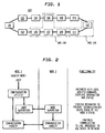
- FIG. 3 shows a block diagram of a network comprised of two sub-networks, sub-network 300 (nodes 301-303) having node numbers 1, 2 and 3, respectively, and sub-network 350 (nodes 351-353) having node numbers 1, 2 and 3, respectively. It is desired to combine sub-networks 300 and 350 into a single sub-network 370 shown in FIG. 4 and node 303 has been chosen as the master node for this building process.
- sub-network 370 shown in FIG. 4 comprises nodes 301-303 and 351-353 and the node numbers 1-6 have been assigned to nodes 301-303 and 351-353 as also shown in FIG. 4.
- Synchronization is a mechanism by which configured nodes that come on-line let the already existing nodes in the sub-network become aware of their existence and their configuration, and inform them that they are ready for operation. Messages are exchanged between the node(s) already on-line and the node(s) coming on-line to perform a validation and security check. Only after a node coming-on line is validated and accepted as belonging to the sub-network, i.e. synchronized, a session establishment between that node and all others is attempted.
- FIG. 5 shows a block diagram of an initial state of communications of sub-network 400 comprised of nodes 401-404. In the initial state, node 404 is not active but is ready to be activated. Further, FIG. 5 shows a block diagram of a final state of communications of sub-network 400 once node 404 is synchronized in accordance with the method described below.
- Nodes can become active or removed from the LAN at any time and they need to be synchronized with all other active nodes before the distributed Voice Messaging System application can become fully operational. Because each Voice Messaging System node is an independent computer, it can become on-line (active) or off-line (de-activate) at any time, in a non-scheduled way, thus a synchronization algorithm should be able to handle single or multiple activation/deactivation of nodes in a random fashion.
- a process for dynamically synchronizing all configured nodes of a distributed Voice Messaging System sub-network is described.
- LAN-ID sub-network unique identifier
- the synchronization algorithm has no concept of master node or slave node, all nodes being considered equals. All nodes execute the same identical software algorithm for the synchronization process.
- the algorithm which follows, uses the broadcast capability of the LAN:
- a background task (or a routine that gets executed periodically) can check if there are nodes configured but not currently synchronized. If such nodes exist, a NODE-UP broadcast can be sent to attempt synchronization. Note that it is not possible to send a message to that specific node, instead of a broadcast, because the address of the adapter controller card is not known. It could very well be that the node was taken out of service to replace a faulty LAN adapter card, in which case the new card will have a different address than the replaced card. Further in accordance with the present invention, configuration information used for security check validation may be sent encrypted.
- the only nodes that need to respond to a NODE-UP message are ones that provide a positive validation of the message.
Abstract
Description
(a) identifying all nodes that belong to the sub-network; (b) gathering configuration information from all these nodes; (c) assigning a new node number to the nodes, if required, and (d) distributing the sub-network map to all the nodes. Only after the new sub-network map is created, distributed, and acknowledged by all nodes in the sub-network can the distributed VMS operate properly.
Claims (5)
- A method for building a sub-network (100; 120) of nodes (105, 106, 107, 109; 111, 112) in a communication network (200), the method comprising the steps of:identifying nodes (105, 106, 107, 109; 111, 112) to be included in the sub-network (100; 120) by a user;sending a broadcast message over the communication network (200), requesting all identified nodes (105, 106, 107, 109; 111, 112) to respond with their configuration information;resolving node configuration information conflicts among the nodes (105, 106, 107, 109; 111, 112) in the sub-network (100; 120);create a sub-network map containing a sub-network ID, physical addresses and node numbers of the nodes (105, 106, 107, 109; 111, 112) of the sub-network (100; 120);distributing the sub-network map to the nodes (105, 106, 107, 109; 111, 112) in the sub-network (100; 120); andsynchronizing the nodes (105, 106, 107, 109; 111, 112) in the sub-network (100; 120), whereby each node (105, 106, 107, 109; 111, 112) sending a NODE-UP broadcast message to all nodes (101 - 112) of the communication network (200).
- The method of claim 1 wherein the step of identifying nodes (105, 106, 107, 109; 111, 112) comprises the step of choosing a node in the communication network (200) at which the identification is made.
- The method of claim 1 wherein the step of identifying nodes (105, 106, 107, 109; 111, 112) comprises the step of identifying nodes (105, 106, 107, 109; 111, 112) by a Group Name.
- The method of claim 1 wherein the step of distributing the sub-network map comprises transmitting the sub-network map to the nodes (105, 106, 107, 109; 111, 112) identified over the communication network (200).
- The method of claim 1 wherein the step of synchronizing comprises the steps of:a node which is to be activated sending the NODE-UP broadcast message on the communication network (200) identifying the sub-network (100; 120);the nodes (105, 106, 107, 109; 111, 112) on the sub-network (100; 120) receiving the NODE-UP broadcast message; andthe nodes (105, 106, 107, 109; 111, 112) on the sub-network (100; 120) transmitting node configuration information to the node to be activated.
Applications Claiming Priority (2)
| Application Number | Priority Date | Filing Date | Title |
|---|---|---|---|
| US08/120,985 US5430730A (en) | 1993-09-14 | 1993-09-14 | Method for building a sub-network in a distributed voice messaging system |
| US120985 | 1993-09-14 |
Publications (3)
| Publication Number | Publication Date |
|---|---|
| EP0643521A2 EP0643521A2 (en) | 1995-03-15 |
| EP0643521A3 EP0643521A3 (en) | 1999-11-03 |
| EP0643521B1 true EP0643521B1 (en) | 2003-06-25 |
Family
ID=22393716
Family Applications (1)
| Application Number | Title | Priority Date | Filing Date |
|---|---|---|---|
| EP94114156A Expired - Lifetime EP0643521B1 (en) | 1993-09-14 | 1994-09-08 | Method for building a sub-network in a distributed voice messaging system |
Country Status (4)
| Country | Link |
|---|---|
| US (1) | US5430730A (en) |
| EP (1) | EP0643521B1 (en) |
| AT (1) | ATE243905T1 (en) |
| DE (1) | DE69432847T2 (en) |
Families Citing this family (43)
| Publication number | Priority date | Publication date | Assignee | Title |
|---|---|---|---|---|
| US5596723A (en) * | 1994-06-23 | 1997-01-21 | Dell Usa, Lp | Method and apparatus for automatically detecting the available network services in a network system |
| US5802286A (en) * | 1995-05-22 | 1998-09-01 | Bay Networks, Inc. | Method and apparatus for configuring a virtual network |
| US5724509A (en) * | 1996-04-22 | 1998-03-03 | Motorola, Inc. | Method and apparatus for synchronizing implementation of configuration information in a communication system |
| US5778058A (en) * | 1996-10-07 | 1998-07-07 | Timeplex, Inc. | Method of adding a new PBX and new PBX port to an existing PBX network |
| US6233234B1 (en) | 1997-06-03 | 2001-05-15 | Bell Atlantic Network Services, Inc. | Secure LAN/internet telephony |
| US20020091784A1 (en) * | 1997-09-10 | 2002-07-11 | Baker Richard A. | Web interface to a device and an electrical network control system |
| US7058693B1 (en) | 1997-09-10 | 2006-06-06 | Schneider Automation Inc. | System for programming a programmable logic controller using a web browser |
| US20020152289A1 (en) * | 1997-09-10 | 2002-10-17 | Schneider Automation Inc. | System and method for accessing devices in a factory automation network |
| US6732191B1 (en) | 1997-09-10 | 2004-05-04 | Schneider Automation Inc. | Web interface to an input/output device |
| US7035898B1 (en) | 1997-09-10 | 2006-04-25 | Schneider Automation Inc. | System for programming a factory automation device using a web browser |
| US7162510B2 (en) * | 1998-03-16 | 2007-01-09 | Schneider Automation Inc. | Communication system for a control system over Ethernet and IP networks |
| US6233626B1 (en) | 1998-10-06 | 2001-05-15 | Schneider Automation Inc. | System for a modular terminal input/output interface for communicating messaging application layer over encoded ethernet to transport layer |
| DE19848341A1 (en) * | 1998-10-21 | 2000-04-27 | Philips Corp Intellectual Pty | Automatic configuration of a bridge terminal for the transmission of data between several sub-networks in a local network |
| US6584102B1 (en) * | 1998-12-21 | 2003-06-24 | At&T Corp. | Communication network apparatus and method |
| US6853867B1 (en) | 1998-12-30 | 2005-02-08 | Schneider Automation Inc. | Interface to a programmable logic controller |
| US6986137B1 (en) * | 1999-09-28 | 2006-01-10 | International Business Machines Corporation | Method, system and program products for managing logical processors of a computing environment |
| US6519660B1 (en) * | 1999-09-28 | 2003-02-11 | International Business Machines Corporation | Method, system and program products for determining I/O configuration entropy |
| US7519737B2 (en) * | 2000-07-07 | 2009-04-14 | Schneider Automation Inc. | Input/output (I/O) scanner for a control system with peer determination |
| US7181487B1 (en) | 2000-07-07 | 2007-02-20 | Schneider Automation Inc. | Method and system for transmitting and activating an application requesting human intervention in an automation network |
| US7032029B1 (en) | 2000-07-07 | 2006-04-18 | Schneider Automation Inc. | Method and apparatus for an active standby control system on a network |
| JP3479834B2 (en) * | 2000-09-04 | 2003-12-15 | 日本電気株式会社 | Wireless access network routing control system and method |
| US7028204B2 (en) * | 2000-09-06 | 2006-04-11 | Schneider Automation Inc. | Method and apparatus for ethernet prioritized device clock synchronization |
| US20020167967A1 (en) * | 2000-09-06 | 2002-11-14 | Schneider Electric | Method for managing bandwidth on an ethernet network |
| US6771651B1 (en) * | 2000-09-29 | 2004-08-03 | Nortel Networks Limited | Providing access to a high-capacity packet network |
| US7023795B1 (en) | 2000-11-07 | 2006-04-04 | Schneider Automation Inc. | Method and apparatus for an active standby control system on a network |
| US20040210664A1 (en) * | 2003-04-17 | 2004-10-21 | Schneider Automation Inc. | System and method for transmitting data |
| EP1766877A4 (en) * | 2004-07-09 | 2008-01-23 | Interdigital Tech Corp | Logical and physical mesh network separation |
| US20060067327A1 (en) * | 2004-09-30 | 2006-03-30 | Behrouz Poustchi | Information distribution system, method and network devices |
| US7593390B2 (en) * | 2004-12-30 | 2009-09-22 | Intel Corporation | Distributed voice network |
| JP2007067995A (en) * | 2005-09-01 | 2007-03-15 | Fujitsu Ltd | Apparatus and method for originating push-to-talk information |
| US7924864B2 (en) | 2006-07-26 | 2011-04-12 | Nokia Corporation | Terminal-based contention free low overhead access |
| US10177957B1 (en) | 2012-07-06 | 2019-01-08 | Cradlepoint, Inc. | Connecting a cloud network to the internet |
| US10135677B1 (en) | 2012-07-06 | 2018-11-20 | Cradlepoint, Inc. | Deployment of network-related features over cloud network |
| US10601653B2 (en) * | 2012-07-06 | 2020-03-24 | Cradlepoint, Inc. | Implicit traffic engineering |
| US10560343B1 (en) | 2012-07-06 | 2020-02-11 | Cradlepoint, Inc. | People centric management of cloud networks via GUI |
| US10110417B1 (en) | 2012-07-06 | 2018-10-23 | Cradlepoint, Inc. | Private networks overlaid on cloud infrastructure |
| US9234757B2 (en) | 2013-11-29 | 2016-01-12 | Fedex Corporate Services, Inc. | Determining node location using a variable power characteristic of a node in a wireless node network |
| US10938816B1 (en) * | 2013-12-31 | 2021-03-02 | Wells Fargo Bank, N.A. | Operational support for network infrastructures |
| US10453023B2 (en) * | 2014-05-28 | 2019-10-22 | Fedex Corporate Services, Inc. | Methods and node apparatus for adaptive node communication within a wireless node network |
| US11238397B2 (en) | 2015-02-09 | 2022-02-01 | Fedex Corporate Services, Inc. | Methods, apparatus, and systems for generating a corrective pickup notification for a shipped item using a mobile master node |
| US10305744B2 (en) | 2015-07-08 | 2019-05-28 | Fedex Corporate Services, Inc. | System, apparatus, and methods of event monitoring for an event candidate related to an ID node within a wireless node network |
| JP6957496B2 (en) | 2016-03-23 | 2021-11-02 | フェデックス コーポレイト サービシズ,インコーポレイティド | Radio node-based methods for auto-tuning the broadcast settings of nodes in a radio node network, non-temporary computer-readable media containing instructions to perform that method, and auto-tuning broadcast node equipment in a radio node network. |
| CN112652310A (en) * | 2020-12-31 | 2021-04-13 | 乐鑫信息科技(上海)股份有限公司 | Distributed speech processing system and method |
Family Cites Families (5)
| Publication number | Priority date | Publication date | Assignee | Title |
|---|---|---|---|---|
| DE3838945A1 (en) * | 1987-11-18 | 1989-06-08 | Hitachi Ltd | NETWORK SYSTEM WITH LOCAL NETWORKS AND WITH A HIERARCHICAL CHOICE OF PATH |
| JPH01245633A (en) * | 1988-03-25 | 1989-09-29 | Nec Corp | Network control system |
| JPH02231843A (en) * | 1989-03-03 | 1990-09-13 | Fujitsu Ltd | System batch management system |
| JPH03158040A (en) * | 1989-11-16 | 1991-07-08 | Fujitsu Ltd | Data transformer |
| US5297138A (en) * | 1991-04-30 | 1994-03-22 | Hewlett-Packard Company | Determining physical topology across repeaters and bridges in a computer network |
-
1993
- 1993-09-14 US US08/120,985 patent/US5430730A/en not_active Expired - Lifetime
-
1994
- 1994-09-08 AT AT94114156T patent/ATE243905T1/en not_active IP Right Cessation
- 1994-09-08 EP EP94114156A patent/EP0643521B1/en not_active Expired - Lifetime
- 1994-09-08 DE DE69432847T patent/DE69432847T2/en not_active Expired - Fee Related
Also Published As
| Publication number | Publication date |
|---|---|
| DE69432847D1 (en) | 2003-07-31 |
| DE69432847T2 (en) | 2004-05-06 |
| US5430730A (en) | 1995-07-04 |
| EP0643521A3 (en) | 1999-11-03 |
| ATE243905T1 (en) | 2003-07-15 |
| EP0643521A2 (en) | 1995-03-15 |
Similar Documents
| Publication | Publication Date | Title |
|---|---|---|
| EP0643521B1 (en) | Method for building a sub-network in a distributed voice messaging system | |
| US6434612B1 (en) | Connection control interface for asynchronous transfer mode switches | |
| US5805924A (en) | Method and apparatus for configuring fabrics within a fibre channel system | |
| CN100555948C (en) | A kind of switching equipment of in the stack exchanger system, being coupled of being used for | |
| CN100477638C (en) | Stack manager protocol with automatic set up mechanism | |
| EP0348331B1 (en) | Method of efficiently updating the topology databases of the nodes in a data communications network | |
| JPS61284144A (en) | Topology data base maintenance for network | |
| US20110188506A1 (en) | Distributed Master Election | |
| JP2009514282A (en) | Network system with high availability | |
| EP1351527B1 (en) | Unique repository server in an operations and maintenance center for a telecommunications system | |
| JP2002057682A (en) | Network interface changeover method and computer connectable to network | |
| US20040064553A1 (en) | Computer network solution and software product to establish error tolerance in a network environment | |
| CN110445657B (en) | Distributed networking management system based on block chain | |
| CN110213359A (en) | A kind of car networking networking data delivery system and method based on D2D | |
| JP3345546B2 (en) | Data delivery method and information communication device | |
| US20020089990A1 (en) | Routing system providing continuity of service for the interfaces associated with neighboring networks | |
| CN113328954B (en) | Method for blocking and limiting transmission of service data packet by source terminal | |
| CN112615944B (en) | Method and system for master-slave synchronization of distributed DNS (Domain name System) | |
| KR101943002B1 (en) | System and method for controlling traffic in tactical service mesh network | |
| JP2001092766A (en) | Client server system and naming service method | |
| JP2003140986A (en) | Remote monitoring system and communication control method | |
| JP2002519874A (en) | Method and communication system for processing state information with a management network having multiple management levels | |
| KR100604593B1 (en) | Method for dynamic reconfiguring cluster system based on configuration information | |
| JP2000181823A (en) | Fault tolerance network management system | |
| JPH0370057A (en) | Inter-computer communication system |
Legal Events
| Date | Code | Title | Description |
|---|---|---|---|
| PUAI | Public reference made under article 153(3) epc to a published international application that has entered the european phase |
Free format text: ORIGINAL CODE: 0009012 |
|
| AK | Designated contracting states |
Kind code of ref document: A2 Designated state(s): AT BE CH DE ES FR GB IT LI NL |
|
| RAP1 | Party data changed (applicant data changed or rights of an application transferred) |
Owner name: SIEMENS ROLM COMMUNICATIONS INC. |
|
| RAP1 | Party data changed (applicant data changed or rights of an application transferred) |
Owner name: SIEMENS BUSINESS COMMUNICATION SYSTEMS, INC. (A DE |
|
| PUAL | Search report despatched |
Free format text: ORIGINAL CODE: 0009013 |
|
| AK | Designated contracting states |
Kind code of ref document: A3 Designated state(s): AT BE CH DE ES FR GB IT LI NL |
|
| 17P | Request for examination filed |
Effective date: 19991206 |
|
| RAP1 | Party data changed (applicant data changed or rights of an application transferred) |
Owner name: SIEMENS INFORMATION AND COMMUNICATION NETWORKS, IN |
|
| 17Q | First examination report despatched |
Effective date: 20020211 |
|
| GRAH | Despatch of communication of intention to grant a patent |
Free format text: ORIGINAL CODE: EPIDOS IGRA |
|
| RTI1 | Title (correction) |
Free format text: METHOD FOR BUILDING A SUB-NETWORK IN A DISTRIBUTED VOICE MESSAGING SYSTEM |
|
| GRAH | Despatch of communication of intention to grant a patent |
Free format text: ORIGINAL CODE: EPIDOS IGRA |
|
| GRAA | (expected) grant |
Free format text: ORIGINAL CODE: 0009210 |
|
| AK | Designated contracting states |
Designated state(s): AT BE CH DE ES FR GB IT LI NL |
|
| PG25 | Lapsed in a contracting state [announced via postgrant information from national office to epo] |
Ref country code: NL Free format text: LAPSE BECAUSE OF FAILURE TO SUBMIT A TRANSLATION OF THE DESCRIPTION OR TO PAY THE FEE WITHIN THE PRESCRIBED TIME-LIMIT Effective date: 20030625 Ref country code: LI Free format text: LAPSE BECAUSE OF FAILURE TO SUBMIT A TRANSLATION OF THE DESCRIPTION OR TO PAY THE FEE WITHIN THE PRESCRIBED TIME-LIMIT Effective date: 20030625 Ref country code: CH Free format text: LAPSE BECAUSE OF FAILURE TO SUBMIT A TRANSLATION OF THE DESCRIPTION OR TO PAY THE FEE WITHIN THE PRESCRIBED TIME-LIMIT Effective date: 20030625 Ref country code: BE Free format text: LAPSE BECAUSE OF FAILURE TO SUBMIT A TRANSLATION OF THE DESCRIPTION OR TO PAY THE FEE WITHIN THE PRESCRIBED TIME-LIMIT Effective date: 20030625 Ref country code: AT Free format text: LAPSE BECAUSE OF FAILURE TO SUBMIT A TRANSLATION OF THE DESCRIPTION OR TO PAY THE FEE WITHIN THE PRESCRIBED TIME-LIMIT Effective date: 20030625 |
|
| REG | Reference to a national code |
Ref country code: GB Ref legal event code: FG4D |
|
| REG | Reference to a national code |
Ref country code: CH Ref legal event code: EP |
|
| REF | Corresponds to: |
Ref document number: 69432847 Country of ref document: DE Date of ref document: 20030731 Kind code of ref document: P |
|
| NLV1 | Nl: lapsed or annulled due to failure to fulfill the requirements of art. 29p and 29m of the patents act | ||
| PG25 | Lapsed in a contracting state [announced via postgrant information from national office to epo] |
Ref country code: ES Free format text: LAPSE BECAUSE OF FAILURE TO SUBMIT A TRANSLATION OF THE DESCRIPTION OR TO PAY THE FEE WITHIN THE PRESCRIBED TIME-LIMIT Effective date: 20031222 |
|
| REG | Reference to a national code |
Ref country code: CH Ref legal event code: PL |
|
| PLBE | No opposition filed within time limit |
Free format text: ORIGINAL CODE: 0009261 |
|
| STAA | Information on the status of an ep patent application or granted ep patent |
Free format text: STATUS: NO OPPOSITION FILED WITHIN TIME LIMIT |
|
| ET | Fr: translation filed | ||
| 26N | No opposition filed |
Effective date: 20040326 |
|
| PGFP | Annual fee paid to national office [announced via postgrant information from national office to epo] |
Ref country code: DE Payment date: 20061120 Year of fee payment: 13 |
|
| PGFP | Annual fee paid to national office [announced via postgrant information from national office to epo] |
Ref country code: GB Payment date: 20070910 Year of fee payment: 14 |
|
| PGFP | Annual fee paid to national office [announced via postgrant information from national office to epo] |
Ref country code: IT Payment date: 20070926 Year of fee payment: 14 |
|
| PGFP | Annual fee paid to national office [announced via postgrant information from national office to epo] |
Ref country code: FR Payment date: 20070918 Year of fee payment: 14 |
|
| PG25 | Lapsed in a contracting state [announced via postgrant information from national office to epo] |
Ref country code: DE Free format text: LAPSE BECAUSE OF NON-PAYMENT OF DUE FEES Effective date: 20080401 |
|
| GBPC | Gb: european patent ceased through non-payment of renewal fee |
Effective date: 20080908 |
|
| REG | Reference to a national code |
Ref country code: FR Ref legal event code: ST Effective date: 20090529 |
|
| PG25 | Lapsed in a contracting state [announced via postgrant information from national office to epo] |
Ref country code: IT Free format text: LAPSE BECAUSE OF NON-PAYMENT OF DUE FEES Effective date: 20080908 |
|
| PG25 | Lapsed in a contracting state [announced via postgrant information from national office to epo] |
Ref country code: FR Free format text: LAPSE BECAUSE OF NON-PAYMENT OF DUE FEES Effective date: 20080930 |
|
| PG25 | Lapsed in a contracting state [announced via postgrant information from national office to epo] |
Ref country code: GB Free format text: LAPSE BECAUSE OF NON-PAYMENT OF DUE FEES Effective date: 20080908 |