EP0643521A2 - Method for building a sub-network in a distributed voice massaging system - Google Patents
Method for building a sub-network in a distributed voice massaging system Download PDFInfo
- Publication number
- EP0643521A2 EP0643521A2 EP94114156A EP94114156A EP0643521A2 EP 0643521 A2 EP0643521 A2 EP 0643521A2 EP 94114156 A EP94114156 A EP 94114156A EP 94114156 A EP94114156 A EP 94114156A EP 0643521 A2 EP0643521 A2 EP 0643521A2
- Authority
- EP
- European Patent Office
- Prior art keywords
- network
- sub
- nodes
- node
- building
- Prior art date
- Legal status (The legal status is an assumption and is not a legal conclusion. Google has not performed a legal analysis and makes no representation as to the accuracy of the status listed.)
- Granted
Links
Images
Classifications
-
- H—ELECTRICITY
- H04—ELECTRIC COMMUNICATION TECHNIQUE
- H04L—TRANSMISSION OF DIGITAL INFORMATION, e.g. TELEGRAPHIC COMMUNICATION
- H04L41/00—Arrangements for maintenance, administration or management of data switching networks, e.g. of packet switching networks
- H04L41/08—Configuration management of networks or network elements
- H04L41/0866—Checking the configuration
- H04L41/0873—Checking configuration conflicts between network elements
-
- H—ELECTRICITY
- H04—ELECTRIC COMMUNICATION TECHNIQUE
- H04L—TRANSMISSION OF DIGITAL INFORMATION, e.g. TELEGRAPHIC COMMUNICATION
- H04L41/00—Arrangements for maintenance, administration or management of data switching networks, e.g. of packet switching networks
- H04L41/08—Configuration management of networks or network elements
- H04L41/0803—Configuration setting
- H04L41/0813—Configuration setting characterised by the conditions triggering a change of settings
- H04L41/082—Configuration setting characterised by the conditions triggering a change of settings the condition being updates or upgrades of network functionality
-
- H—ELECTRICITY
- H04—ELECTRIC COMMUNICATION TECHNIQUE
- H04L—TRANSMISSION OF DIGITAL INFORMATION, e.g. TELEGRAPHIC COMMUNICATION
- H04L41/00—Arrangements for maintenance, administration or management of data switching networks, e.g. of packet switching networks
- H04L41/08—Configuration management of networks or network elements
- H04L41/085—Retrieval of network configuration; Tracking network configuration history
- H04L41/0853—Retrieval of network configuration; Tracking network configuration history by actively collecting configuration information or by backing up configuration information
-
- H—ELECTRICITY
- H04—ELECTRIC COMMUNICATION TECHNIQUE
- H04M—TELEPHONIC COMMUNICATION
- H04M3/00—Automatic or semi-automatic exchanges
- H04M3/42—Systems providing special services or facilities to subscribers
- H04M3/50—Centralised arrangements for answering calls; Centralised arrangements for recording messages for absent or busy subscribers ; Centralised arrangements for recording messages
- H04M3/53—Centralised arrangements for recording incoming messages, i.e. mailbox systems
- H04M3/533—Voice mail systems
- H04M3/53325—Interconnection arrangements between voice mail systems
Abstract
Description
- The present invention relates to a method of building a sub-network in a distributed Voice Messaging System (VMS) connected by a Local Area Network (LAN) and dynamically synchronizing all the nodes of the VMS.
- Distributed Voice Messaging System (VMS) networks in the art have existed on Local Area Networks (LANs). However, in such implementations, the entire LAN has been devoted to the VMS network. This is inefficient, for example, because it requires a company to purchase and maintain several LANs in order to provide connectivity for a computer network as well as for a VMS network. Further, this approach inhibits possible connectivity between the two or more types of networks.
- In light of this, there is a need in the art for sub-networks of voice messaging systems which comprises a portion of a communications network such as a LAN. In addition, there is a need in the art for one or more of such sub-networks to coexist on the same communications network. In further addition, there is a need in the art for a method for building such sub-networks of distributed voice messaging systems on a LAN.
- Advantageously, embodiments of the present invention provide a method for building sub-networks of distributed Voice Messaging Systems (VMSs) on a communications network such as a Local Area Network (LAN).
- For a distributed, sub-network of VMSs to operate properly, all Voice Messaging (VM) nodes in the sub-network must be configured with a sub-network map. The sub-network map is a data structure that contains information relating to all VM nodes that belong to the sub-network. The minimum information that must be contained in the sub-network map (one entry for each node in the sub-network is included in the sub-network map) is: (a) a node number for each node in the sub-network (a node number is a unique identifier for a node in a sub-network); (b) a group name (a group name is an identifier of one or more nodes in a LAN network); (c) a Local Area Network Identifier (a LAN-ID is an identifier of a sub-network); and (d) a physical address of a LAN Adapter Card for each node (this is a unique identifier of each LAN adapter card in the VMS which is read from the adapter card).
- The building process of a sub-network includes: (a) identifying all nodes that belong to the sub-network; (b) gathering configuration information from all these nodes; (c) assigning a new node number to the nodes, if required, and (d) distributing the sub-network map to all the nodes. Only after the new sub-network map is created, distributed, and acknowledged by all nodes in the sub-network can the distributed VMS operate properly.
- While building the sub-network one must take care of concurrency and synchronization of other applications or utilities that may be executing in any or all of the VMS nodes in the sub-network being built. For example, if two nodes start the building process at the same time, collisions can occur and the process could fail. Safeguards must be included in the building process to guarantee a successful sub-network build or to clearly identify problems.
- An embodiment of the present invention is a method for building a sub-network of nodes in a communication network, the method comprising the steps of: (a) identifying nodes to be included in the sub-network; (b) gathering node configuration information from the nodes identified; (c) resolving node configuration information conflicts among the nodes in the sub-network; (d) create a sub-network map; (e) distributing the sub-network map to the nodes in the sub-network; and (f) synchronizing the nodes in the sub-network.
-
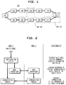
- FIG. 1 shows a block diagram of nodes which are connected in a Local Area Network;
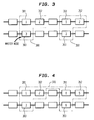
- FIG. 2 shows a block diagram of the software modules that embody the inventive method and their architecture with respect to nodes in the network;
- FIG. 3 shows a block diagram of a communication network comprised of two sub-networks of voice messaging systems;
- FIG. 4 shows a block diagram of a communications network wherein the two sub-networks of FIG. 3 have been combined into a single sub-network; and
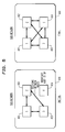
- FIG. 5 shows a block diagram of an initial state of communications of a sub-network wherein one node is not active and a block diagram of a final state of communications of the sub-network once the node is synchronized in accordance with the inventive method.
- FIG. 1 shows a block diagram of nodes 101-112 which are connected in a Local Area Network 200 (LAN 200). Some of the nodes could be computers and some of the nodes could be voice messaging systems. If all the nodes connected to
LAN 200 are Voice Messaging (VM) nodes that are to be included in a distributed Voice Messaging System (VMS) network, then we refer to the inventive method as building a network. However, if only some of the nodes connected toLAN 200 are to be included as part of the distributed VMS , then we refer to the inventive method as building a sub-network. As further shown in FIG. 1, VMSsub-network 100 is comprised of VM 105-107 and 109 and VMSsub-network 120 is comprised of VM 111-112. As those of ordinary skill in the art will readily appreciate, the case of building a sub-network in a distributed Voice Messaging System encompasses the case of building a network. - Although there are several ways of specifying which nodes are to be included in the sub-network, a node selection technique using a Group Name will be described. In accordance with this preferred embodiment of the inventive method, only VM nodes connected to
LAN 200 having the same Group Name will be included in the sub-network. - All nodes are considered equal in a fully distributed VMS. However, in accordance with the inventive method, once the building process starts, a node that initiates the building process is considered to be a master node as far as the building process is concerned. Despite this, by having all nodes equal, the building process can be initiated from any of the nodes in the VMS and by specifying a master node once the process starts, the master node can easily control the complete process and decide on actions to take if an error condition occurs.
- For a distributed Voice Messaging Application to operate properly, all nodes in the VMS must have a unique node number. If there are one or more duplicate node numbers, they need to be resolved to successfully build a sub-network. In accordance with the inventive method, to resolve node numbering conflicts, a manual or automatic building mode can be specified by a user at the beginning of the building process. In the manual build mode, the user resolves the duplicate node number conflict by changing the node number of the nodes that are in conflict. In the automatic build mode, a utility which will be described below resolves the duplicate node number conflict by changing the node number of the nodes that are in conflict. For a process description of the automatic build mode please see Appendix A.
- FIG. 2 shows a block diagram of software modules that embody the inventive method and their architecture with respect to nodes in the network. As shown in FIG. 2, the software modules that embody the building process are formulated in a layered architecture, as in the well known ISO-OSI Network Architecture model, with some modifications. Each layer implements a specific functionality with the lower layers, offering services to the layers above. However, the preferred embodiment of the present invention extends the ISO-OSI Network Architecture model in that a higher layer can directly request services from any layer below and is not restricted to receiving services from a layer immediately below it. As shown in FIG. 2, the three layers involved in embodying the inventive method, starting from the top, are:
- (a) The Configuration Utility (Config. Util.) is software that runs in an Application Layer that interacts with the user and that may request user input or confirmation. The Config. Util. initiates and sequences the building process. It makes sure that all the VM nodes requested by the user are included in the sub-network and it displays status information related to the building process.
- (b) Node Supervisor (NS) Layer contains software that offers services to the Application Layer. These services include: (i) keeping track of all utilities being executed in the Application Layer at a VM node; (ii) keeping track of which applications are active in the Application Layer at the VM node (referred to as the state of the VM node); and (iii) locking or excluding a utility from executing if the utility conflicts with the current state of the VM node. Each utility has an attribute list attached thereto which specifies: (i) the system state under which it is allowed to execute and (ii) the identity of other utilities with which it can execute simultaneously. The software at the NS layer also has the capability of modifying a node's configuration parameters with the sub-network map.
- (c) Communication Handler (CH) Layer contains software that offers services to software in the Application Layer and the NS Layer. The software in the CH controls and establishes communication between all nodes in the sub-network. The software has the capability of sending and receiving messages from any node, and it can also send broadcast messages to all nodes physically connected to the LAN. It knows the configuration parameter values for its own node, and can respond with them when queried from another node. Once a sub-network is configured, this module's function is to synchronize and create a communication channel with all other VM nodes in the sub-network.
- The goals of the building process are: (a) to have a simple design; (b) to minimize communication among nodes; (c) to have one layer in a VM node communicate with the same layer in a different node; (d) to have a robust process that always succeeds, or if any inconsistency is detected, terminates with clear and meaningful messages to the user; (e) to allow initiating the building process from any of the nodes in the sub-network being build; (f) to avoid the existence of redundant information in the building process, and (g) to allow for a secure process (if desired).
- The steps described below are carried out by software which executes on the computers at the VM nodes in the LAN.
- When a voice messaging node is created, default values are assigned to Group Name, node number, and LAN-ID. In the preferred embodiment, these values are "VMS" for Group Name, 1 for node number, and 0 for LAN-ID.
- The detailed description of each step required to build a sub-network follows. The preferred embodiment of the inventive method requires a user to, at least, configure each VM node to have a Group Name (otherwise the default value is used). It also requires that each VM node have a LAN Adapter Card with a physical address that is unique, and that each VM node knows its own physical address. The following are the steps of the inventive method:
- 1. (User -> Config Util.): A user executes the Config. Util. at a node to build a sub-network, and specifies the Group Name of all VM nodes that are to be included. Thus, in this embodiment, Group Names are used to identify nodes to be included in sub-networks. The user chooses either a Manual or an Automatic node numbering mode. For a description of the Automatic node numbering mode, please refer to Appendix A. The node at which the building method starts is considered the master node.
- 2. (Config Util. -> CH): Then, the Config. Util. requests the CH to gather network map information from all nodes in the network that have the same Group Names as those specified by the user.
- 3. (CH - master node): Then, the CH at the master node sends a broadcast message over the LAN requesting all VM nodes in the LAN with the Group Names specified by the use to respond with their configuration information (Node Number, Group Name, LAN-ID and LAN adapter card physical address).
- 4. (CH - all nodes): All VM nodes in the LAN receive the broadcast message (including the master node) and check the request. Only if a VM node belongs to the Group Names that were specified in the broadcast will it respond to the master node with its configuration information.
- 5. (CH - master node): The master node waits for t1 sec, enough time to guarantee that all nodes in the LAN have time to process the request and respond to it. The master node then processes all the responses and it returns the network map of all the responding nodes to the Config. Util. The time-out of t1 is system dependent, and for one particular application a value of 10 sec was used.
- 6. (Config Util): The Config. Util., interacting with the user, is responsible for the network map validation and conflict resolution. Validation of the network map implies checking the maximum number of nodes in the sub-network. If the user selected an Automatic build mode, then any node number conflict will be automatically solved by the utility (refer to Appendix A for a description). If the Manual build mode was selected, the Config. Util. would display all the duplicate node numbers and the user would change the configuration of the conflictive nodes and restart the building process. Once all conflicts are resolved, the user will confirm and the building process will proceed. The Config. Util. generates a new unique LAN-ID to identify a new sub-network. In the preferred embodiment, this is done by combining the master node's LAN Adapter Card physical address with a time stamp. One can readily see that the LAN-ID is utilized to address nodes in the sub-network. Thus, while it is possible for a a node which is added to the network later to have the same Group Name as previous nodes, it will not be placed on the same sub-network without a further building process since its LAN-ID will be different.
- 7. (Config Util. -> NS): Config. Util. requests NS to proceed with the building process. Config. Util. passes a new network map with a LAN-ID, physical LAN addresses and node numbers to NS at the master node.
- 8. (NS - master node): NS proceeds with a two way commit protocol. First, it sends requests to NS(s) on all nodes in the sub-network to execute a lock to insure a successful build. A lock should guarantee that no other utility affecting the build process can be executed. The lock also insures that voice messaging applications remain inactive during the building process.
- 9. (NS - all nodes): When an NS at a node receives the request, it attempts to execute the lock and replies to the master node NS with status and error information where appropriate. Status information could be positive (an acknowledgment of a successful lock) or negative (rejection of the lock).
- 10. (NS - master node): NS at the master node times out on a wait if not all replies are received within t2 sec. No reply from a node is equivalent to a negative reply. In the preferred embodiment, one negative reply terminates the entire building process. An example of an error condition is a failed lock due to a conflict with a concurrent network building process being performed on another node. Error information is used by Config. Util. to provide feedback to the user. If the building process is terminated, NS at the master node sends unlock requests to all the sub-network nodes to cancel the lock. To guarantee that a node does not remain locked in case of failures during the building process (such failures being caused, for example, by the master node going down or by losing connection), NS at each node implements a lock-time-out mechanism. In accordance with the lock time-out mechanism, an NS at a node will automatically unlock after t3 sec if no further requests are received from the master NS. Timers t2 and t3 are system dependent. For example, in an embodiment of the present invention, values of 10 sec and 30 sec were used respectively.
- 11. (NS - master node): If and only if a positive acknowledgment is received from all the nodes in the new sub-network map, the building process will continue. The next step is for master node's NS to send the new sub-network map to the NS of all the VM node in the sub-network.
- 12. (NS - all nodes): NS at each node receives the new network map, updates its network configuration information, executes unlock, and replies to the master node that the building process was successful.
- 13. (NS - master node): The building process is considered successful if and only if the master node NS receives positive acknowledgments from all the nodes in the new sub-network. As in (step 10) NS on a master node times out if all nodes do not reply within t2 sec. Refer to step 10 for a recovery mechanism if a positive reply is not received within the specified time period.
- 14. (NS -> Config Util.): NS at a master node returns a build status and error information to the Config. Util. The Config. Util. then notifies the user of the build outcome. Build status (successful or not) and an error message, if applicable, are reported to the user. The user can, at this point, correct the problem(s) and attempt a new build.
- 15. (Config Util. -> CH): The Config. Util. notifies the CH to read the new network map. If the map read by the CH is different from the map it had, it will immediately send a request to all CHs in the sub-network to read the new network map. The CHs will then start the automatic synchronization process with all other nodes. No acknowledgment is required to be sent back to the master node. For a detailed description of the synchronization process, please refer to Appendix B. All nodes in the sub-network execute a background consistency check processes that verifies that all nodes are synchronized. In the event that a node is not synchronized and does not accept the synchronization requests from other nodes, an error is logged and alarms go off.
- The time that it takes to complete the sub-network building process depends mainly on the time-out values that are used. We have discovered that values of 10 and 30 sec were enough to guarantee response from all nodes in a particular VMS. However, as those of ordinary skill in the art readily appreciate, the time out values depend on the type of LAN and number of nodes connected.
- As one of ordinary skill in the art can readily appreciate, having one node act as a master for the building process allows for centralized error reporting and synchronization of the operation in all nodes. For example, the execution of each step in the building process requires that all of the requirements of the previous steps must have been fulfilled by all nodes. Of course, the use of a master node does not preclude starting the building process from any node in the sub-network.
- Even though the Voice Messaging System nodes to be included in the sub-network were specified using the Group Name, the inventive building process allows for different ways of specifying the nodes in the sub-network. The particular way used in a particular building process can be selected by the user at build time. In accordance with the present invention, nodes are notified of the build type with a special coded value sent in the broadcast. Other types of node selection are:
- (a) Each node can be assigned a specific node name, and nodes in the sub-network can be selected by specifying the node names.
- (b) Nodes can be specified by node numbers, as long as there are no conflicts.
- Because computers can be deactivated, removed from the network, or can crash at any time, time-outs are used by all nodes to assure that if an acknowledgment or the next build command is not received, the building process is aborted and resources de-allocated. Even though the recovery mechanisms can be made as sophisticated as desired, in some cases a simpler mechanism may be used to simplify the development effort.
- If security is of importance and the environment is a non-cooperative one, mechanisms can be implemented in the building process to guarantee that once the build starts (i.e.. a master node selected), no other node can take the place of the master node, and that once the network map is accepted (i.e. the nodes in the sub-network are selected) no node can be substituted:
The master node can fully identify itself in the initial broadcast and when nodes respond they can specifically address messages to the master node. Then, the master node will discard messages from any node not in the initial sub-network map. - All nodes that respond to the initial master node broadcast may also fully identify themselves. From this point on, the master node can send messages to individual nodes instead of using the broadcast mechanism. Individual nodes will discard messages from any node other than the master node.
- As those of ordinary skill in the art will readily appreciate, the building process is independent of how closely coupled the VM nodes are. That is, the inventive process will work well with loosely or tightly coupled nodes.
- Lastly, advantageously, in accordance with the present invention, the user is not required to provide network configuration parameters in any node before the building process starts. The only configuration parameters that are required to be set are those that are specific to the node, like the Group Name and Node number for a manual build. After a network is successfully built, it will automatically update all the nodes in the sub-network with the new network map.
- Those skilled in the art will recognize that the foregoing description has been presented for the sake of illustration and description only. As such, it is not intended to be exhaustive or to limit the invention to the precise form disclosed. For example, modifications and variations are possible in light of the above teaching which are considered to be within the spirit of the present invention. Thus, it is to be understood that the claims appended hereto are intended to cover all such modification and variations which fall within the true scope and spirit of the invention.


Claims (6)
- A method for building a sub-network of nodes in a communication network, the method comprising the steps of:
identifying nodes to be included in the sub-network;
gathering node configuration information from the nodes identified;
resolving node configuration information conflicts among the nodes in the sub-network;
create a sub-network map;
distributing the sub-network map to the nodes in the sub-network; and
synchronizing the nodes in the sub-network. - The method of claim 1 wherein the step of identifying nodes comprises the step of choosing a node in the network at which the identification is made.
- The method of claim 1 wherein the step of gathering node configuration information comprises the steps of:
transmitting a broadcast message in the network;
receiving the broadcast message; and
transmitting node configuration information by the nodes identified. - The method of claim 1 wherein the step of identifying nodes comprises the step of identifying nodes by Group Name.
- The method of claim 1 wherein the step of distributing the sub-network map comprises transmitting the sub-network map to the nodes identified over the network.
- The method of claim 1 wherein the step of synchronizing comprises the steps of:
a node which is to be activated sending a broadcast message on the network identifying the sub-network;
the nodes on the sub-network receiving the message; and
the nodes on the sub-network transmitting node configuration information to the node to be activated.
Applications Claiming Priority (2)
| Application Number | Priority Date | Filing Date | Title |
|---|---|---|---|
| US120985 | 1993-09-14 | ||
| US08/120,985 US5430730A (en) | 1993-09-14 | 1993-09-14 | Method for building a sub-network in a distributed voice messaging system |
Publications (3)
| Publication Number | Publication Date |
|---|---|
| EP0643521A2 true EP0643521A2 (en) | 1995-03-15 |
| EP0643521A3 EP0643521A3 (en) | 1999-11-03 |
| EP0643521B1 EP0643521B1 (en) | 2003-06-25 |
Family
ID=22393716
Family Applications (1)
| Application Number | Title | Priority Date | Filing Date |
|---|---|---|---|
| EP94114156A Expired - Lifetime EP0643521B1 (en) | 1993-09-14 | 1994-09-08 | Method for building a sub-network in a distributed voice messaging system |
Country Status (4)
| Country | Link |
|---|---|
| US (1) | US5430730A (en) |
| EP (1) | EP0643521B1 (en) |
| AT (1) | ATE243905T1 (en) |
| DE (1) | DE69432847T2 (en) |
Cited By (1)
| Publication number | Priority date | Publication date | Assignee | Title |
|---|---|---|---|---|
| WO2008012614A2 (en) * | 2006-07-26 | 2008-01-31 | Nokia Corporation | System map for inter- and intra- clique contention free communication |
Families Citing this family (42)
| Publication number | Priority date | Publication date | Assignee | Title |
|---|---|---|---|---|
| US5596723A (en) * | 1994-06-23 | 1997-01-21 | Dell Usa, Lp | Method and apparatus for automatically detecting the available network services in a network system |
| US5802286A (en) * | 1995-05-22 | 1998-09-01 | Bay Networks, Inc. | Method and apparatus for configuring a virtual network |
| US5724509A (en) * | 1996-04-22 | 1998-03-03 | Motorola, Inc. | Method and apparatus for synchronizing implementation of configuration information in a communication system |
| US5778058A (en) * | 1996-10-07 | 1998-07-07 | Timeplex, Inc. | Method of adding a new PBX and new PBX port to an existing PBX network |
| US6233234B1 (en) | 1997-06-03 | 2001-05-15 | Bell Atlantic Network Services, Inc. | Secure LAN/internet telephony |
| US20020152289A1 (en) * | 1997-09-10 | 2002-10-17 | Schneider Automation Inc. | System and method for accessing devices in a factory automation network |
| US6732191B1 (en) | 1997-09-10 | 2004-05-04 | Schneider Automation Inc. | Web interface to an input/output device |
| US20020091784A1 (en) * | 1997-09-10 | 2002-07-11 | Baker Richard A. | Web interface to a device and an electrical network control system |
| US7035898B1 (en) | 1997-09-10 | 2006-04-25 | Schneider Automation Inc. | System for programming a factory automation device using a web browser |
| US7058693B1 (en) | 1997-09-10 | 2006-06-06 | Schneider Automation Inc. | System for programming a programmable logic controller using a web browser |
| US7162510B2 (en) * | 1998-03-16 | 2007-01-09 | Schneider Automation Inc. | Communication system for a control system over Ethernet and IP networks |
| US6233626B1 (en) | 1998-10-06 | 2001-05-15 | Schneider Automation Inc. | System for a modular terminal input/output interface for communicating messaging application layer over encoded ethernet to transport layer |
| DE19848341A1 (en) * | 1998-10-21 | 2000-04-27 | Philips Corp Intellectual Pty | Automatic configuration of a bridge terminal for the transmission of data between several sub-networks in a local network |
| US6584102B1 (en) * | 1998-12-21 | 2003-06-24 | At&T Corp. | Communication network apparatus and method |
| US6853867B1 (en) | 1998-12-30 | 2005-02-08 | Schneider Automation Inc. | Interface to a programmable logic controller |
| US6986137B1 (en) * | 1999-09-28 | 2006-01-10 | International Business Machines Corporation | Method, system and program products for managing logical processors of a computing environment |
| US6519660B1 (en) * | 1999-09-28 | 2003-02-11 | International Business Machines Corporation | Method, system and program products for determining I/O configuration entropy |
| US7032029B1 (en) | 2000-07-07 | 2006-04-18 | Schneider Automation Inc. | Method and apparatus for an active standby control system on a network |
| US7519737B2 (en) * | 2000-07-07 | 2009-04-14 | Schneider Automation Inc. | Input/output (I/O) scanner for a control system with peer determination |
| US7181487B1 (en) | 2000-07-07 | 2007-02-20 | Schneider Automation Inc. | Method and system for transmitting and activating an application requesting human intervention in an automation network |
| JP3479834B2 (en) * | 2000-09-04 | 2003-12-15 | 日本電気株式会社 | Wireless access network routing control system and method |
| US7028204B2 (en) * | 2000-09-06 | 2006-04-11 | Schneider Automation Inc. | Method and apparatus for ethernet prioritized device clock synchronization |
| US20020167967A1 (en) * | 2000-09-06 | 2002-11-14 | Schneider Electric | Method for managing bandwidth on an ethernet network |
| US6771651B1 (en) * | 2000-09-29 | 2004-08-03 | Nortel Networks Limited | Providing access to a high-capacity packet network |
| US7023795B1 (en) | 2000-11-07 | 2006-04-04 | Schneider Automation Inc. | Method and apparatus for an active standby control system on a network |
| US20040210664A1 (en) * | 2003-04-17 | 2004-10-21 | Schneider Automation Inc. | System and method for transmitting data |
| MXPA06015212A (en) * | 2004-07-09 | 2007-03-15 | Interdigital Tech Corp | Logical and physical mesh network separation. |
| US20060067327A1 (en) * | 2004-09-30 | 2006-03-30 | Behrouz Poustchi | Information distribution system, method and network devices |
| US7593390B2 (en) * | 2004-12-30 | 2009-09-22 | Intel Corporation | Distributed voice network |
| JP2007067995A (en) * | 2005-09-01 | 2007-03-15 | Fujitsu Ltd | Apparatus and method for originating push-to-talk information |
| US10601653B2 (en) * | 2012-07-06 | 2020-03-24 | Cradlepoint, Inc. | Implicit traffic engineering |
| US10135677B1 (en) | 2012-07-06 | 2018-11-20 | Cradlepoint, Inc. | Deployment of network-related features over cloud network |
| US10560343B1 (en) | 2012-07-06 | 2020-02-11 | Cradlepoint, Inc. | People centric management of cloud networks via GUI |
| US10110417B1 (en) | 2012-07-06 | 2018-10-23 | Cradlepoint, Inc. | Private networks overlaid on cloud infrastructure |
| US10177957B1 (en) | 2012-07-06 | 2019-01-08 | Cradlepoint, Inc. | Connecting a cloud network to the internet |
| US10078811B2 (en) | 2013-11-29 | 2018-09-18 | Fedex Corporate Services, Inc. | Determining node location based on context data in a wireless node network |
| US10938816B1 (en) * | 2013-12-31 | 2021-03-02 | Wells Fargo Bank, N.A. | Operational support for network infrastructures |
| US10453023B2 (en) | 2014-05-28 | 2019-10-22 | Fedex Corporate Services, Inc. | Methods and node apparatus for adaptive node communication within a wireless node network |
| US11238397B2 (en) | 2015-02-09 | 2022-02-01 | Fedex Corporate Services, Inc. | Methods, apparatus, and systems for generating a corrective pickup notification for a shipped item using a mobile master node |
| US9985839B2 (en) | 2015-07-08 | 2018-05-29 | Fedex Corporate Services, Inc. | Systems, apparatus, and methods of event monitoring for an event candidate within a wireless node network based upon sighting events, sporadic events, and benchmark checkpoint events |
| EP3433809A4 (en) | 2016-03-23 | 2019-10-02 | Fedex Corporate Services, Inc. | Systems, apparatus, and methods for self-adjusting a broadcast setting of a node in a wireless node network |
| CN112652310A (en) * | 2020-12-31 | 2021-04-13 | 乐鑫信息科技(上海)股份有限公司 | Distributed speech processing system and method |
Citations (4)
| Publication number | Priority date | Publication date | Assignee | Title |
|---|---|---|---|---|
| JPH01245633A (en) * | 1988-03-25 | 1989-09-29 | Nec Corp | Network control system |
| JPH02231843A (en) * | 1989-03-03 | 1990-09-13 | Fujitsu Ltd | System batch management system |
| US5018133A (en) * | 1987-11-18 | 1991-05-21 | Hitachi, Ltd. | Network system comprising a plurality of LANs using hierarchical routing |
| US5130980A (en) * | 1989-11-16 | 1992-07-14 | Fujitsu Limited | Data communication system with protection of error propagation |
Family Cites Families (1)
| Publication number | Priority date | Publication date | Assignee | Title |
|---|---|---|---|---|
| US5297138A (en) * | 1991-04-30 | 1994-03-22 | Hewlett-Packard Company | Determining physical topology across repeaters and bridges in a computer network |
-
1993
- 1993-09-14 US US08/120,985 patent/US5430730A/en not_active Expired - Lifetime
-
1994
- 1994-09-08 AT AT94114156T patent/ATE243905T1/en not_active IP Right Cessation
- 1994-09-08 DE DE69432847T patent/DE69432847T2/en not_active Expired - Fee Related
- 1994-09-08 EP EP94114156A patent/EP0643521B1/en not_active Expired - Lifetime
Patent Citations (4)
| Publication number | Priority date | Publication date | Assignee | Title |
|---|---|---|---|---|
| US5018133A (en) * | 1987-11-18 | 1991-05-21 | Hitachi, Ltd. | Network system comprising a plurality of LANs using hierarchical routing |
| JPH01245633A (en) * | 1988-03-25 | 1989-09-29 | Nec Corp | Network control system |
| JPH02231843A (en) * | 1989-03-03 | 1990-09-13 | Fujitsu Ltd | System batch management system |
| US5130980A (en) * | 1989-11-16 | 1992-07-14 | Fujitsu Limited | Data communication system with protection of error propagation |
Non-Patent Citations (2)
| Title |
|---|
| PATENT ABSTRACTS OF JAPAN vol. 013, no. 584 (E-866), 22 December 1989 (1989-12-22) & JP 01 245633 A (NEC CORP), 29 September 1989 (1989-09-29) * |
| PATENT ABSTRACTS OF JAPAN vol. 014, no. 546 (E-1008), 4 December 1990 (1990-12-04) & JP 02 231843 A (FUJITSU LTD), 13 September 1990 (1990-09-13) * |
Cited By (3)
| Publication number | Priority date | Publication date | Assignee | Title |
|---|---|---|---|---|
| WO2008012614A2 (en) * | 2006-07-26 | 2008-01-31 | Nokia Corporation | System map for inter- and intra- clique contention free communication |
| WO2008012614A3 (en) * | 2006-07-26 | 2008-04-10 | Nokia Corp | System map for inter- and intra- clique contention free communication |
| US7924864B2 (en) | 2006-07-26 | 2011-04-12 | Nokia Corporation | Terminal-based contention free low overhead access |
Also Published As
| Publication number | Publication date |
|---|---|
| EP0643521B1 (en) | 2003-06-25 |
| ATE243905T1 (en) | 2003-07-15 |
| EP0643521A3 (en) | 1999-11-03 |
| DE69432847D1 (en) | 2003-07-31 |
| US5430730A (en) | 1995-07-04 |
| DE69432847T2 (en) | 2004-05-06 |
Similar Documents
| Publication | Publication Date | Title |
|---|---|---|
| EP0643521A2 (en) | Method for building a sub-network in a distributed voice massaging system | |
| US6959337B2 (en) | Networked system for assuring synchronous access to critical facilities | |
| US5253252A (en) | Token device for distributed time scheduling in a data processing system | |
| US6434612B1 (en) | Connection control interface for asynchronous transfer mode switches | |
| Lamport | Paxos made simple | |
| CN110086652B (en) | Management system and method for service network element in 5G core network | |
| EP0533407A2 (en) | Heterogeneous transaction coordination | |
| EP0713307A2 (en) | Method and apparatus for configuring fabrics within a fibre channel system | |
| CN109005045B (en) | Main/standby service system and main node fault recovery method | |
| JP2009514282A (en) | Network system with high availability | |
| JPH07319793A (en) | Method and apparatus for execution of distributed algorithm or service on computer network based on simple network management protocol | |
| JP4922178B2 (en) | Method and apparatus for coordinating information between managers and agents in a management network | |
| EP1577776B1 (en) | Method and apparatus for data synchronization in a distributed data base system | |
| US5463763A (en) | Apparatus and method for supervising multiprocessor communications using messages transmitted between processors in a circular fashion | |
| CN100493079C (en) | Method for main node supporting different agreement type secondary unit apparatus on secondary node | |
| US7240088B2 (en) | Node self-start in a decentralized cluster | |
| JP3730545B2 (en) | Service control application execution method and system | |
| JPH0646130A (en) | Renewal method of software for distributed call processing system of communication network | |
| CN116095145A (en) | Data control method and system of VPC cluster | |
| JP3345546B2 (en) | Data delivery method and information communication device | |
| US7583690B2 (en) | Allocation of station addresses to communication users in a bus system | |
| US11496564B2 (en) | Device state synchronization method and common capability component | |
| CN114095946A (en) | 5GC service network element management system and management method thereof | |
| JP2002544730A (en) | Method of connecting a network element to a telecommunications system | |
| JP2003085060A (en) | Distributed processing system, relay computer, processing computer, relay computer program and processing computer program |
Legal Events
| Date | Code | Title | Description |
|---|---|---|---|
| PUAI | Public reference made under article 153(3) epc to a published international application that has entered the european phase |
Free format text: ORIGINAL CODE: 0009012 |
|
| AK | Designated contracting states |
Kind code of ref document: A2 Designated state(s): AT BE CH DE ES FR GB IT LI NL |
|
| RAP1 | Party data changed (applicant data changed or rights of an application transferred) |
Owner name: SIEMENS ROLM COMMUNICATIONS INC. |
|
| RAP1 | Party data changed (applicant data changed or rights of an application transferred) |
Owner name: SIEMENS BUSINESS COMMUNICATION SYSTEMS, INC. (A DE |
|
| PUAL | Search report despatched |
Free format text: ORIGINAL CODE: 0009013 |
|
| AK | Designated contracting states |
Kind code of ref document: A3 Designated state(s): AT BE CH DE ES FR GB IT LI NL |
|
| 17P | Request for examination filed |
Effective date: 19991206 |
|
| RAP1 | Party data changed (applicant data changed or rights of an application transferred) |
Owner name: SIEMENS INFORMATION AND COMMUNICATION NETWORKS, IN |
|
| 17Q | First examination report despatched |
Effective date: 20020211 |
|
| GRAH | Despatch of communication of intention to grant a patent |
Free format text: ORIGINAL CODE: EPIDOS IGRA |
|
| RTI1 | Title (correction) |
Free format text: METHOD FOR BUILDING A SUB-NETWORK IN A DISTRIBUTED VOICE MESSAGING SYSTEM |
|
| GRAH | Despatch of communication of intention to grant a patent |
Free format text: ORIGINAL CODE: EPIDOS IGRA |
|
| GRAA | (expected) grant |
Free format text: ORIGINAL CODE: 0009210 |
|
| AK | Designated contracting states |
Designated state(s): AT BE CH DE ES FR GB IT LI NL |
|
| PG25 | Lapsed in a contracting state [announced via postgrant information from national office to epo] |
Ref country code: NL Free format text: LAPSE BECAUSE OF FAILURE TO SUBMIT A TRANSLATION OF THE DESCRIPTION OR TO PAY THE FEE WITHIN THE PRESCRIBED TIME-LIMIT Effective date: 20030625 Ref country code: LI Free format text: LAPSE BECAUSE OF FAILURE TO SUBMIT A TRANSLATION OF THE DESCRIPTION OR TO PAY THE FEE WITHIN THE PRESCRIBED TIME-LIMIT Effective date: 20030625 Ref country code: CH Free format text: LAPSE BECAUSE OF FAILURE TO SUBMIT A TRANSLATION OF THE DESCRIPTION OR TO PAY THE FEE WITHIN THE PRESCRIBED TIME-LIMIT Effective date: 20030625 Ref country code: BE Free format text: LAPSE BECAUSE OF FAILURE TO SUBMIT A TRANSLATION OF THE DESCRIPTION OR TO PAY THE FEE WITHIN THE PRESCRIBED TIME-LIMIT Effective date: 20030625 Ref country code: AT Free format text: LAPSE BECAUSE OF FAILURE TO SUBMIT A TRANSLATION OF THE DESCRIPTION OR TO PAY THE FEE WITHIN THE PRESCRIBED TIME-LIMIT Effective date: 20030625 |
|
| REG | Reference to a national code |
Ref country code: GB Ref legal event code: FG4D |
|
| REG | Reference to a national code |
Ref country code: CH Ref legal event code: EP |
|
| REF | Corresponds to: |
Ref document number: 69432847 Country of ref document: DE Date of ref document: 20030731 Kind code of ref document: P |
|
| NLV1 | Nl: lapsed or annulled due to failure to fulfill the requirements of art. 29p and 29m of the patents act | ||
| PG25 | Lapsed in a contracting state [announced via postgrant information from national office to epo] |
Ref country code: ES Free format text: LAPSE BECAUSE OF FAILURE TO SUBMIT A TRANSLATION OF THE DESCRIPTION OR TO PAY THE FEE WITHIN THE PRESCRIBED TIME-LIMIT Effective date: 20031222 |
|
| REG | Reference to a national code |
Ref country code: CH Ref legal event code: PL |
|
| PLBE | No opposition filed within time limit |
Free format text: ORIGINAL CODE: 0009261 |
|
| STAA | Information on the status of an ep patent application or granted ep patent |
Free format text: STATUS: NO OPPOSITION FILED WITHIN TIME LIMIT |
|
| ET | Fr: translation filed | ||
| 26N | No opposition filed |
Effective date: 20040326 |
|
| PGFP | Annual fee paid to national office [announced via postgrant information from national office to epo] |
Ref country code: DE Payment date: 20061120 Year of fee payment: 13 |
|
| PGFP | Annual fee paid to national office [announced via postgrant information from national office to epo] |
Ref country code: GB Payment date: 20070910 Year of fee payment: 14 |
|
| PGFP | Annual fee paid to national office [announced via postgrant information from national office to epo] |
Ref country code: IT Payment date: 20070926 Year of fee payment: 14 |
|
| PGFP | Annual fee paid to national office [announced via postgrant information from national office to epo] |
Ref country code: FR Payment date: 20070918 Year of fee payment: 14 |
|
| PG25 | Lapsed in a contracting state [announced via postgrant information from national office to epo] |
Ref country code: DE Free format text: LAPSE BECAUSE OF NON-PAYMENT OF DUE FEES Effective date: 20080401 |
|
| GBPC | Gb: european patent ceased through non-payment of renewal fee |
Effective date: 20080908 |
|
| REG | Reference to a national code |
Ref country code: FR Ref legal event code: ST Effective date: 20090529 |
|
| PG25 | Lapsed in a contracting state [announced via postgrant information from national office to epo] |
Ref country code: IT Free format text: LAPSE BECAUSE OF NON-PAYMENT OF DUE FEES Effective date: 20080908 |
|
| PG25 | Lapsed in a contracting state [announced via postgrant information from national office to epo] |
Ref country code: FR Free format text: LAPSE BECAUSE OF NON-PAYMENT OF DUE FEES Effective date: 20080930 |
|
| PG25 | Lapsed in a contracting state [announced via postgrant information from national office to epo] |
Ref country code: GB Free format text: LAPSE BECAUSE OF NON-PAYMENT OF DUE FEES Effective date: 20080908 |