EP0641993B1 - Shape measuring apparatus - Google Patents
Shape measuring apparatus Download PDFInfo
- Publication number
- EP0641993B1 EP0641993B1 EP94306489A EP94306489A EP0641993B1 EP 0641993 B1 EP0641993 B1 EP 0641993B1 EP 94306489 A EP94306489 A EP 94306489A EP 94306489 A EP94306489 A EP 94306489A EP 0641993 B1 EP0641993 B1 EP 0641993B1
- Authority
- EP
- European Patent Office
- Prior art keywords
- net
- data
- image
- delaunay triangulation
- display
- Prior art date
- Legal status (The legal status is an assumption and is not a legal conclusion. Google has not performed a legal analysis and makes no representation as to the accuracy of the status listed.)
- Expired - Lifetime
Links
Images


Classifications
-
- G—PHYSICS
- G01—MEASURING; TESTING
- G01S—RADIO DIRECTION-FINDING; RADIO NAVIGATION; DETERMINING DISTANCE OR VELOCITY BY USE OF RADIO WAVES; LOCATING OR PRESENCE-DETECTING BY USE OF THE REFLECTION OR RERADIATION OF RADIO WAVES; ANALOGOUS ARRANGEMENTS USING OTHER WAVES
- G01S7/00—Details of systems according to groups G01S13/00, G01S15/00, G01S17/00
- G01S7/48—Details of systems according to groups G01S13/00, G01S15/00, G01S17/00 of systems according to group G01S17/00
- G01S7/481—Constructional features, e.g. arrangements of optical elements
-
- G—PHYSICS
- G01—MEASURING; TESTING
- G01B—MEASURING LENGTH, THICKNESS OR SIMILAR LINEAR DIMENSIONS; MEASURING ANGLES; MEASURING AREAS; MEASURING IRREGULARITIES OF SURFACES OR CONTOURS
- G01B11/00—Measuring arrangements characterised by the use of optical techniques
- G01B11/24—Measuring arrangements characterised by the use of optical techniques for measuring contours or curvatures
-
- G—PHYSICS
- G01—MEASURING; TESTING
- G01C—MEASURING DISTANCES, LEVELS OR BEARINGS; SURVEYING; NAVIGATION; GYROSCOPIC INSTRUMENTS; PHOTOGRAMMETRY OR VIDEOGRAMMETRY
- G01C11/00—Photogrammetry or videogrammetry, e.g. stereogrammetry; Photographic surveying
- G01C11/04—Interpretation of pictures
- G01C11/06—Interpretation of pictures by comparison of two or more pictures of the same area
-
- G—PHYSICS
- G01—MEASURING; TESTING
- G01S—RADIO DIRECTION-FINDING; RADIO NAVIGATION; DETERMINING DISTANCE OR VELOCITY BY USE OF RADIO WAVES; LOCATING OR PRESENCE-DETECTING BY USE OF THE REFLECTION OR RERADIATION OF RADIO WAVES; ANALOGOUS ARRANGEMENTS USING OTHER WAVES
- G01S17/00—Systems using the reflection or reradiation of electromagnetic waves other than radio waves, e.g. lidar systems
- G01S17/88—Lidar systems specially adapted for specific applications
- G01S17/89—Lidar systems specially adapted for specific applications for mapping or imaging
Definitions
- the present invention relates to an image processing method and apparatus and more particularly to a method and apparatus for processing data defining 3-D geometrical shape using triangular patches.
- range finders which are designed to radiate a beam to a target object (an object to be measured) to determine a distance to the object by taking advantage of the beam reflected from the object and by carrying out two-dimensional optical scan over the entire object, thus obtaining the distance information on the object.
- the methods for measuring a distance to an object which are employed in the aforesaid range finders, there is a method, wherein an optical pulse is emitted to the object and the distance is determined by measuring the time required for the optical pulse to reflect back from the object, and there is another method, wherein a beam with its intensity modulated into a sine wave is launched into a target object and the distance to the target object is determined by detecting the phase difference between the beam reflected from the object and the original beam.
- the recent progress in semiconductor lasers and the high-frequency circuit technology has enabled these methods to measure distances with a resolution of 1 mm or less and they are used for measuring the position of an object located at a short distance, identifying an object and the like.
- a shape measuring apparatus which is designed to emit a beam from a light source to an object via reflecting mirrors, and at this time, the reflecting mirrors are driven by driving means to two-dimensionally scan the object with the beam in order to detect the changes in the optical path length by utilizing the beam reflected from the object, thus measuring the shape of the object (references: OPTOELECTRONICS (1985, No. 12, pp. 59, by Seiji Inokuchi, et al.).
- an object to be measured is spatially held or rested. This makes it necessary to have the object undergo two-dimensional optical scanning from restricted directions, presenting a problem in that the rear, top or bottom surface, etc. of the object cannot be measured.
- the image distance information obtained by using the shape measuring apparatus described above is referred to as a range image. More specifically, in the range image, the information on depth and position is stored in each picture element position thereof, while in a variable-density image or color image taken by a typical camera or the like, information on brightness is stored in each picture element position thereof.
- the range image is normally an image measured from a single direction as in the case of photographing with a camera. Hereinafter, this will be referred to as a projective range image.
- a range image provided with the positional information on full circumference directions of a target object is called a radial range image, the positional information being obtained by performing measurement in full circumference directions of the target object.
- a range finder for measuring a distance along a single vertical line is fixed around an object to be measured or rotated around it by a fixed rotary system, thereby measuring each line.
- This conventional method is disadvantageous in that a significantly larger measuring apparatus structure than an object to be measured is required, and the apparatus is hard to move toward the object, leading to poor mobility and high cost.
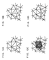
- a Delaunay triangulation net shown in FIG. 12A when a point marked with x in FIG. 12B is designated, a triangle wherein this point lies in a circumcircle is looked for.
- pj (xj, yj)
- pk (xk, yk)
- the prior art (1), (2) or (3) discussed above makes it possible to acquire point positions in a 3-D space such as in an indoor scene or a 3-D object.
- the 3-D shape of a 3-D space such as in an indoor scene or of a 3-D object, the point positions alone are not sufficient; it is necessary to determine a surface constituted by the points.
- the shape of the object is described by polygons which have same size; therefore, smaller polygons must be used to represent a complicated surface shape. If, however, more polygons are used, then more than necessary polygons would be used for a uniform surface shape such as a large plane. This results in significant waste in memories used and also it causes other problems, including slow displaying speed.
- the above techniques attempt to display the details of the shape of the object regardless of the resolution of the display unit or the resolution of the observer's vision even when the object occupies only a small portion of a display screen, i.e., even when the angle of view is small, because of a viewpoint set by the observer. This applies more load than necessary to the display unit.
- XP 000075065 discloses a slit-ray projection method to obtain range data of an object, in which the object is modelled using triangular patches.
- an image processing apparatus as set out in claim 1.
- the present invention also provides an image processing method as set out in claim 13.
- a shape measuring unit constituting a part of an image processing apparatus of a first reference system is designed so that, when it holds an object to be measured (hereinafter referred to as "target object") in a capsule made of a light-transmitting material by means of supporting members and radiates a beam from a light source provided outside the capsule to the target object via the capsule, it relatively moves the capsule with respect to an incident direction of the beam by a driving means provided on the capsule to change the beam radiating positions on the target object and it detects the beam reflected from the target object by a detecting means, thereby measuring the shape of the target object by utilizing a signal received from the detecting means.
- target object an object to be measured
- a driving means provided on the capsule to change the beam radiating positions on the target object and it detects the beam reflected from the target object by a detecting means, thereby measuring the shape of the target object by utilizing a signal received from the detecting means.
- FIG. 1 is the schematic diagram showing the configuration of the first reference system
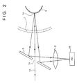
- FIG. 2 is the enlarged explanatory drawing of a part of FIG. 1.
- a laser oscillator 1 serves as a light source and it emits laser beams.
- An optical modulator 2 modulates the intensity of a laser beam received from the laser oscillator 1.
- An oscillator 3 drives the optical modulator 2.
- a beam splitter 4 divides the modulated laser beam into reference light La and measurement light Lb.
- a photodiode 9 detects the intensity of the reference light La provided by the beam splitter 4.
- a reflecting member 5 has an aperture 5A (see FIG. 2) at the center thereof. The measurement light Lb from the beam splitter 4 is launched into a target object 6 through the aperture 5a of the reflecting member 5.
- the target object 6 is held in a spherical capsule 7 made of a light-transmitting material, e.g., glass.
- Motors 13 and 14 constitute an element of a driving means 16, which drives the capsule 7.
- a condenser lens 8 converges the measurement light Lb, which reflects off the target object 6 and then reflects from the reflecting member 5, and leads it into a photodiode 10.
- the photodiode 10 detects the intensity of the measurement light Lb based on the beam reflected from the target object 6 as it will be discussed later.
- a phase measuring unit 11 determines a phase difference between the reference light La and the measurement light Lb detected respectively by the photodiodes 9 and 10.
- An information processor 12 controls the driving means 16, changes the incident position of the measurement light Lb launched into the target object 6, and determines, by computation, a shape of the target object 6 from a difference in light path according to a signal received from the phase measuring unit 11 for each incident position of the measurement light Lb.
- the intensity of the laser beam from the laser oscillator 1 is modulated by means of the optical modulator 2 and the laser beam is divided through the beam splitter 4 into two beams; one for the reference light La and the other for the measurement light Lb.
- the reference light Lb from the beam splitter 4 passes through the aperture 5a of the reflecting member 5 and irradiates a point 6a of the target object 6 via the capsule 7 as shown in FIG. 2.
- the beam, which has been reflected and scattered from the target object 6, passes through the capsule 7 again before it enters the reflecting member 5.
- the beam reflected from the reflecting member 5 is led into the photodiode 10 via the condenser lens 8.
- the reference light Lb provided by the beam splitter 4 is launched into the photodiode 9.
- the phase measuring unit 11 measures the phase difference between the reference light La and the measurement light Lb launched respectively into the photodiodes 9, 10 and applies the measurement result to the information processor 12.
- the information processor 12 determines the difference in optical path between the reference light La and the measurement light Lb from the information on the phase difference and a modulated frequency supplied by the optical modulator 2.
- the driving means 16 moves the capsule 7 in a predetermined direction, which will be discussed later, so that the beam is launched into the target object from all directions.
- the difference in optical path is determined on every direction of the target object and the shape of the target object is determined in accordance with a publicly known method.
- FIG. 3A is the explanatory view of the major section of a supporting mechanism of the target object 6 in this system and FIG. 3B is the explanatory view of a part taken on line A-A.
- numeral 15a denotes a threaded hole provided in the capsule 7
- numeral 15b denotes a screw, i.e., the supporting member, which is screwed into the threaded hole.
- the target object 6 is supported at four points with the supporting members 15b.
- the target object 6 housed in the capsule 7 is fixed approximately at the center of the capsule 7 by adjusting the lengths of the supporting members 15b projecting into the capsule 7. After fixing the object, the portions of the supporting members extending outside the capsule 7 are cut off.
- FIG. 4A and FIG. 4B are the explanatory view showing the data structure of the geodetic dome for determining the rotational direction and rotational angle of the capsule 7 driven by the driving means of FIG. 1.
- FIG. 4A shows the appearance of the geodetic dome and
- FIG. 4B shows the development thereof.
- the information processor 12 calculates the latitude or longitude of each vertex of the geodetic dome shown in FIG. 4 and controls the drive of the motors 13, 14 so that the measurement light Lb is radiated to the corresponding points on the capsule 7.
- the shape of object 6 at the contacted portion, where the supporting member 15b is in contact with the target object 6, is interpolated from a neighborhood value.
- This system is configured so that the target object 6 is housed in the spherical capsule 7, which is rotated according to the rotational direction and the rotational angle determined from the geodetic dome shown in FIG. 4 with respect to the incident direction of the beam from the light source, thereby optically scanning the target object, however, the configuration is not limited to this; it may alternatively be configured as follows:
- capsule 7 needs not be necessarily sealed hermetically as long as it encloses the target object and it can be rotated at a desired angle by the driving means. In addition, the capsule 7 needs not necessarily transmit the beam uniformly from all directions.
- the shape measuring apparatus is capable of measuring the shape in every direction with high accuracy by configuring the shape measuring apparatus as described above when optically scanning the target object to measure the shape thereof.
- the method for obtaining the radial range image according to the second reference system includes a step of generating depth data for calibration, wherein an object for calibration is disposed at a plurality of different rotational angles around the rotation axis and the depth of the object for calibration is measured for each rotational angle in order to generate the depth data for calibration, a step of calculating the rotation axis, wherein the positional data on the rotation axis, which rotates the object for calibration, are calculated from the depth data for calibration, a rotation step, wherein the target object is rotated around the rotation axis by a predetermined rotational angle, a step of generating depth data, wherein the depth data are generated by measuring the depth of the target object for each predetermined rotational angle, and a step of calculating actual coordinates, wherein the coordinates of the target object in actual space are measured by applying the depth data and the positional data of
- the apparatus for obtaining the radial range image includes a depth data generating means, whereby an object for calibration is disposed at a plurality of different rotational angles around the rotation axis and the depth of the object for calibration is measured for each rotational angle in order to generate the depth data for calibration, a means for calculating the rotation axis, whereby the positional data on the rotation axis, which rotates the object for calibration, are calculated from the depth data for calibration, a rotating means, whereby the target object is rotated around the rotation axis by a predetermined rotational angle, a depth data generating means, whereby the depth data are generated by measuring the depth of the target object for each predetermined rotational angle, and a means for calculating actual coordinates, whereby the coordinates of the target object in actual space are measured by applying the depth data and the positional data on the rotation axis.
- the method for obtaining the radial range image is designed to dispose the object for calibration at a plurality of different rotational angles, measure the depth of the object for calibration for each rotational angle to generate the depth data, calculate the positional data on the rotation axis, around which the object for calibration is rotated, from the depth data, rotate the target object by the predetermined rotational angle, measure the depth for each line to the target object for each predetermined rotational angle to generate depth data, and calculate the coordinates of the depth data in actual space by applying the positional data on the rotation axis.
- a means for generating depth data for calibration disposes the object for calibration at a plurality of different rotational angles, measures the depth of the object for calibration for each rotational angle, and generates depth data
- a means for calculating the rotation axis calculates the positional data on the rotation axis, around which rotates the object for calibration is rotated, from the depth data
- a rotating means rotates the target object by the predetermined rotational angle
- a depth data generating means measures the depth for one line of the target object for each predetermined rotational angle to generate the depth data
- the means for calculating actual coordinates calculates the coordinates of the depth data in actual space by applying the positional data of the rotation axis.
- FIG. 5 shows the basic configuration of the apparatus for obtaining the radial range image.
- the apparatus for obtaining the radial range image is roughly divided into image processing system 120 and image measuring system 121.
- the image measuring system 121 obtains projective range image data and radial range image data from a target object and processes the data before sending them to the image processing system 120.
- Image processing system 120 employs the received projective range image data, the received radial range image data or the like to calculate the position of a turntable 109, performing arithmetic operation for determining the actual coordinates in actual space, which correspond to the radial range image data, modulating the luminance of the range images to display them on a window system 104, or performing other image processing.
- CPU A 101 executes data processing, arithmetic operation, and data receiving by processing programs stored beforehand in memory A 102.
- Memory B 103 saves data to be processed.
- the window system 104 is the display system, which displays processes and results of processing.
- Keyboard 105 is used to enter user's instructions or data.
- Pointing device 106 is used to enter user's instructions through window system 104.
- Bus 111 is data transmission lines for data transferred to and from the devices mentioned above.
- Memory B 103 stores projective range image data d1 and radial range image d3 obtained by range image measuring apparatus 110, and measurement point position data d2, which is obtained by executing the rotation axis calibration program and the rotational geometrical transformation program stored beforehand in the memory A 102.
- Data receiving program p1 stored beforehand in memory A 102 controls network controller A 140 to receive and store the data obtained by the range image measuring apparatus 110 in memory B 103 via bus B 112, network controller B 141, and network lines 113.
- CPU B 107 controls range image measuring apparatus 110 and turntable 109.
- turntable control program p5 for controlling turntable 109, on which a target object is rested and data transfer program p6 for transferring measurement data to memory B 103 are stored beforehand in a memory C 108.
- These programs are read by the CPU B 107 to execute various types of processing.
- the rotational angle of turntable 109, whereon the target object is rested, is controlled by the CPU B 107.
- Projective range image measuring apparatus 110 obtains depth information by projecting light to the target object and receiving the reflected light, which is controlled by the CPU B 107.
- Bus B 112 is used for data transmission among the devices.
- Network lines 113 is an interface connecting bus A 111 and the bus B 112, the data transmission through the interface being controlled by network controller A 113 and network controller B 141.
- FIG. 6, FIG. 7, and FIG. 8 illustrate the processing flows for obtaining a radial range image. More specifically, FIG. 6 and FIG. 7 shows the processing flows of the method for determining the rotation axis of turntable 109, while FIG. 8 shows the processing flow for the measurement of the object by applying the determined rotation axis to the acquisition of the radial range image.
- Steps S201, S202, S204, and S205 are implemented in image measuring system 121, while other steps are implemented in image processing system 120.
- step S201 an object for calibration, which has at least two planes, such as a quadrangular prism and triangular prism, is placed on turntable 109 with its bottom surface down. At this time, the angle formed by the two planes may be unknown.
- the accurate size of the object for calibration may be unknown as long as the size is appropriate for the turntable and the measuring apparatus.
- step S202 range image measuring apparatus control program p4 controls range image measuring apparatus 110 to set a predetermined rotational angle, whereat the two planes can be measured simultaneously, thereby performing the projective range image measurement on the object for calibration.
- Data transfer program p6 controls network controller B 141 and sends the obtained projective range image measurement data to image processing system 120 to trigger the processing of step S203.
- Image processing system 120 stores the entered projective range image measurement data in area d1 of memory B 103, and image processing system 120 begins the processing from step S203.
- Image measuring system 121 executes the processing, which begins with the step S204.
- step S203 two plane areas are cut out from the projective range image data stored in area d1 of memory B 103.
- This processing is accomplished by finding the closest line from measurements by taking advantage of the already known fact that the target object has two planes, which are convexly connected, facing against the measuring apparatus.
- the image is cut into two areas with the line, and the surrounding edges of the cut areas are deleted. The deletion of the edge portions is necessary because the data on the surrounding edges are usually unstable.
- plane formula (1.1L) The plane formula for the left plane area of the first measurement image thus obtained is hereinafter referred to as plane formula (1.1L).
- step S208 a plane approximation calculation is performed by using the information on the surface position of each picture element in the obtained right plane area. This is accomplished by applying the data in the formula (1) for the plane to determine the estimated values of coefficients a, b, c, and d in the same manner as in step S207.
- the plane formula for the right plane area of the first measurement image thus obtained is hereinafter referred to as plane formula (1.1R).
- step S220 the system waits for the second measurement data sent from the image measuring system.
- the data is stored in area d1 of memory B 103.
- the program then proceeds to step S206.
- the processing performed in the steps S206, S209, and S210 is basically the same as that carried out in steps S203, S207, and S208 with only difference of whether the image data received first or second is processed.
- step S206 two plane areas are cut out according to the projective range image data received second, which is stored in area d1 of memory B 103.
- step S209 the plane approximation calculation is carried out by applying the information on the surface position of each picture element in the obtained left plane area. This is accomplished by applying the data to the formula (1) for the plane to determine the estimated values of coefficients a, b, c, and d.
- plane formula (1.2L) The plane formula for the left plane area of the second measurement image thus obtained is hereinafter referred to as plane formula (1.2L).
- step S210 the plane approximation calculation is performed by employing the information on the surface position of each picture element in the obtained right plane area. This is accomplished by applying the data to the formula (1) for the plane to determine the estimated values of coefficients a, b, c, and d in the same manner as in the step S209.
- the plane formula for the right plane area of the second measurement image thus obtained is hereinafter referred to as plane formula (1.2R).
- a plane is determined which passes an intersection line of the plane formula (1.1L) and the plane formula (1.2L), and also bisects the angle between the plane based on formula (1.1L) and the plane based on formula (1.2L).
- the obtained plane is referred to as a plane formula (1.3).
- a plane is determined which passes an intersection line of the plane formula (1.1R) and the plane formula (1.2R), and also bisects the plane based on formula (1.1R) and the plane based on formula (1.2R).
- the obtained plane is referred to as a plane formula (1.4).
- step S213 the intersection line of the plane formula (1.3) and the plane formula (1.4) is calculated.
- steps S303 and S307 are carried out by image processing system 120, while other steps are carried out by the image measuring system 121.
- step S301 an object to be measured is rested on the turntable.
- the rotational angle is regarded as zero degree.
- the range image for each line is measured by range imaging apparatus 110. This measurement can be accomplished by swinging a polygon mirror once when a range image measuring apparatus based on scanning by means of a laser-beam polygon mirror is used.
- the obtained distance data is transferred to image processing system 120 via network controller A 141 and stored in area d3 of memory B 103.
- FIG. 9 shows the contour of object 942 placed on turntable 109.
- the distance is measured while rotating object 942 around rotation axis 941.
- the distance for each line in the direction of the Z axis is measured, and the measurement results are entered in 2-D data table 943 shown in FIG. 9.
- the range image data of the 2-D data table are stored in d3 of memory B 103.
- the axis of abscissa of 2-D data table 943 denotes the rotational angle of turntable 109, while the axis of ordinate denotes the height of the rotation axis, i.e., measurement in the direction of the Z axis.
- the range image data on one point of object 942 are stored in each unit of the matrix of 2-D data table 943.
- step S303 the obtained measurement points are subjected to geometrical transformation.
- the obtained range image data on the measurement points are the results of the measurements made as the object was rotated by the turntable.
- the coordinates in actual space can be obtained by carrying out the rotational geometric transformation, which sets the measurement points back to their original positions before the rotation. This processing allows the proper surface position of the object to be obtained.
- an apparent measurement point position is taken as (x,y,z)
- the total rotation angle as - ⁇
- the proper object surface position as (x', y', z')
- the measurement of the points on the one line means direct measurement of the position on the surface of the object.
- step S307 the point position data of each line obtained in step S303 are stored in area d3 of memory B 103 of image processing system 120.
- step S304 the turntable is rotated by a minute angle.
- step S305 the total sum of the minute rotational angles of the turntable rotated in step S304 is calculated.
- step S306 it is checked whether the total sum of the minute turns has reached a full one rotation; if not, the program goes back to step S302 to repeat the measurement, and if it has reached the full one rotation, then the measurement will be terminated.
- the measurement of the range image of the object from all directions can be achieved.
- FIG. 10 shows an obtained range image of the object with the luminance modulated, the image being displayed on window system 104.
- the range image measuring apparatus 110 which uses a light-receiving surface element as in the slit light projection method or a pattern light projection method, may alternatively be used as the projective range image measuring apparatus.
- the measuring apparatus 110 uses a light-receiving surface element as in the slit light projection method or a pattern light projection method.
- the system provides the following effects.
- the data on a radial range image which covers the shape data from every direction around the target object, can be easily generated at low cost without using a measuring apparatus, which is extremely larger than the target object or using a large-scale measuring apparatus, which turns itself.
- the radial range image data can be obtained by setting the target object and automatically measuring the position of the rotation axis, around which the object is rotated, thus permitting easy measurement.
- the position of the target object can be set freely and the measurement of the radial range image can be performed at low cost.
- the image processing method of the third reference system includes a step for interactively selecting and entering discrete points on an object in 3-D space and a step for generating a model having a 3-D geometrical shape by employing triangular patches, which apply the Delaunay triangulation net in accordance with the points entered in an input step.
- An image processing apparatus is equipped with an input means for interactively selecting and entering discrete points on the object in 3-D space and a generating means for generating a model having a 3-D geometrical shape by employing triangular patches, which apply the Delaunay triangulation net in accordance with the points entered through the input means.
- the discrete points of the object in 3-D space are interactively selected and entered through such steps or such a configuration according to the third reference system. Then, based on the entered points, a model having a 3-D geometrical shape is generated by triangular patches using the Delaunay triangulation net.
- the third reference system will be explained in detail.
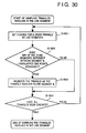
- FIG. 15 shows the processing flow of the triangular patch generating method of this system.
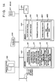
- FIG. 14 is the block diagram showing an apparatus, which implements the method. The following gives detailed explanation of the processing carried out by CPU 1403 of the system, which functions as a processing unit, a related processing procedure (program) being stored in memory 1401.
- a Delaunay triangulation net is updated by designating the corresponding points of the right and left images, respectively, by means of mouse 1407 or other pointing device (step S302).
- the processing in step S302 program routines rr1 through rr3 stored in memory 1401) will be discussed later with reference to the flowchart.
- step S303 Designating the corresponding points is repeated until it is terminated in step S303. If termination is designated, then all element-triangles of the Delaunay triangulation net are transformed, in step S304, to triangular patch data, which is output through I/O unit 1405.
- step S302 The processing in aforesaid step S302 will now be described in accordance with the flowchart given in FIG. 16.
- the processing includes designating of the points by means of the mouse and updating the Delaunay triangulation net.
- step S401 the system waits for an input given through a mouse used for designating a point. If no instruction is given in step S402 as to whether the system should exit the waiting for an input, then a new generating point is designated in step S403 or a generating point to be deleted is designated in step S405. The generating point designated in step S403 is added to the Delaunay triangulation net in step S404.
- the processing will be discussed later with reference to the flowchart shown in FIG. 17. This processing is the same as that discussed earlier.
- step S405 The generating point designated in step S405 is deleted from the Delaunay triangulation net in a step S406. This processing will be discussed later with reference to the flowchart shown in FIG. 18.
- step S501 an element triangle in the Delaunay triangulation net is checked to determine whether the point to be added lies inside a circumcircle in order to decide which element triangle of the current Delaunay triangulation net should be updated, and the triangle, which includes the point to be added inside the circumcircle, is registered (step S502). This processing is carried out on all triangles (step S503).
- steps S501 through S503 correspond to FIG. 12C. Whether a certain point is located inside the circumcircle of a triangle can be determined as shown below.
- step S504 all triangles that include the point to be added inside circumcircles have been selected.
- the selected triangles are combined into a single polygonal area A (step S504).
- step S505 the triangles in this polygonal area A are deleted (step S505), and triangles, which are formed by applying two adjoining vertexes on the contour line of polygonal area A and the point to be added, are named triangle group B (step S506).
- steps S504 through S506 correspond to FIG. 13.
- polygonal area A in the original Delaunay triangulation net is replaced by triangle group B to generate a new Delaunay triangulation net (step S507).
- the Delaunay triangulation net is updated in steps S501 through S507.
- the Delaunay triangulation net shown in FIG. 12A is updated to the Delaunay triangulation net shown in FIG. 12D.
- step S406 for deleting the generating point mentioned previously will now be described with reference to the flowchart of FIG. 18 and FIG. 19.
- step S601 Select triangles, which have the designated generating point to be deleted (FIG. 19A) as a middle point thereof (step S601). This selection results in a hatched section shown in FIG. 19B.
- This triangle group is named as polygonal area C (step S602), then the triangles in this polygonal area C are deleted (step S603). This eliminates the generating point designated to be deleted and also the triangles involving the generating point. At this point, there is no triangulation net in polygonal area C; therefore, processing for regenerating a triangulation net will be carried out as follows.
- a Delaunay triangulation net which is entirely different from the previous Delaunay triangulation net, is generated (step S604).
- the processing for generating the Delaunay triangulation net in step S604 will be discussed later in connection with the flowchart shown in FIG. 20.
- the Delaunay triangulation net obtained in step S604 may have a triangle outside polygonal area C (an example is shown in FIG. 22A - 22F); therefore, the triangle, which lies in the Delaunay triangulation net generated in step S604 but which has been generated outside polygonal area C is deleted in step S605.
- Step S605 will be discussed later with reference to the flowchart of FIG. 21.
- the triangle group thus obtained replaces polygonal area C in step S606 to delete the generating point and update the Delaunay triangulation net. It can be mathematically proved that the method for updating the Delaunay triangulation net in steps S601 through 606 maintains characteristics of the Delaunay triangulation net.
- step S801 one of the vertexes of the polygon is selected (step S801) and the generating point designated in FIG. 13 is added in step S802. These steps S801 and S802 are carried out on all vertexes (step S803) to generate the Delaunay triangulation net applying the vertexes of polygonal area C.
- a clockwise circulation list of the vertexes is generated along the contour of polygonal area C (step S901, FIG. 22D). Then, for each triangle of the Delaunay triangulation net, a clockwise circulation list of the vertexes is generated (step S902, FIG. 22E). If any of the triangles is located outside polygonal area C, then the triangles share the vertex, which has the opposite list direction as shown in FIG. 22F. Therefore, in step S903, it is checked whether the list directions are reversed and if any reversed list direction is found, the triangle having the opposite list direction is deleted from the triangle group (FIG. 22F). The processing of steps S903 and S904 is carried out on all triangles (step S905) to delete triangles lying outside polygonal area C.
- FIG. 23 shows the stereo image read in step S301.
- FIG. 24 shows a state, wherein designation is performed by means of the mouse in step S302 and it is the state, wherein the system is waiting for an input in the step S401.
- FIG. 25 shows a result of designating a new point in step S403 from the state shown in FIG. 24 and adding the generating point in the step S404 (point P in FIG. 25).
- FIG. 26 shows a result of designating a generating point to be deleted in the step S405 from the state shown in FIG. 25 and deleting the generating point in step S406 (point Q in FIG. 25).
- the above system is an example, which combines the method, whereby a position of a point in a scene is determined by designating corresponding points in the stereo images and the designated point is added as a generating point to update the Delaunay triangulation net, and the method, whereby the Delaunay triangulation net is updated by deleting an existing generating point.
- the following describes the fourth reference system, which includes a method, whereby edges of the triangulation net is fixed, in addition to the two methods mentioned above.
- the configuration of the apparatus of the fourth reference system is the same as that of the third reference system. This applies to the fifth reference system and one after the fifth reference system to be discussed later.
- FIG. 27 The basic flowchart of this system is similar to that of the third reference system described above and to that of FIG. 15.
- the flow of the processing performed in step S302 is shown in FIG. 27 (corresponding to FIG. 16 in the third reference system). The description will be given with reference to FIG. 27.
- step S1501 The processing implemented in step S1501 is identical to that of step S401. Then, when no instruction is given as to whether the system should exit the waiting-for-input state in step S1502, a new generating point is designated in step S1503, a generating point to be deleted is designated in step S1504, two generating points are designated for fixing the line segment connecting the two generating points as an edge in step S1505, or an existing fixed edge is designated for clearing the fixation thereof in step S1506.
- step S1507 the processing for adding a new generating point to the Delaunay triangulation net (step S1507) is carried out as shown by the flowchart of FIG. 17.
- step S1504 the processing for deleting the point from the Delaunay triangulation net (step S1508) is carried out as shown by the flowchart of FIG. 18.
- step S1505 If it is determined that two existing generating points have been designated for fixing an edge in step S1505, then the processing is performed in step S1509. In step S1509, an edge designated to be fixed is stored one after another.
- Step S1510 which is the part of the processing for storing a fixed edge to be cleared, and in this step, the designated fixed edge is erased from fixed edges, which have been stored in step S1509, thereby clearing the fixation of the designated fixed edge.
- step S1507 After completion of step S1507, S1508, S1509 or S1510, the system proceeds to step S1511.
- step S1511 the edges designated to be fixed, which have been stored for fixation in steps S1509, are actually fixed. The processing implemented in step S1511 will be described with reference to the flowchart given in FIG. 28.
- step S1601 it is checked whether there is any line segment that has been specified for fixation.
- a line segment to be fixed is designated in step S1509. If it is found that no line segment has been designated for fixation, then the system exits the processing for fixing a edge, or if there is any, then the system goes to step S1602.
- the processing implemented in step S1602 and its subsequent steps will be described below.
- a line segment connecting the two generating points (FIG. 29B) designated is determined as a fixed edge in step S1602, and this line segment is named E.
- Triangles involving line segment E are selected in step S1603. The processing for selecting the triangles, which involve the line segment of step S1603, will be discussed later in connection with FIG. 30.
- the selection result is shown by the hatched part of FIG. 29C.
- This triangle group is temporarily named as polygonal area D (step S1604).
- the triangles in polygonal area D are eliminated in step S1605. This completes eliminating the triangles involving the aforesaid line segment.
- a triangulation net, which retains the aforesaid line segment as an edge, will be generated in polygonal area D.
- step S1606 polygonal area D is divided into two polygonal areas D1 and D2 with the aforesaid line segment as a boundary thereof (FIG. 29D).
- the Delaunay triangulation net which is completely independent from the original Delaunay triangulation net having the points as the generating points, is generated (step S1607).
- a Delaunay triangulation net is generated (step S1609) (FIG. 29E).
- the processing for generating the Delaunay triangulation nets in two steps, S1607 and S1609, is illustrated by the flowchart shown in FIG. 20.
- the Delaunay triangulation nets obtained by steps S1607 and S1609 may include triangles outside the polygonal areas (e.g., the cases shown in FIG. 22 and FIG. 29F). Therefore, the triangles generated outside polygonal areas D1 and D2 are deleted in steps S1608 and S1610 from the Delaunay triangulation nets generated in steps S1607 and S1609.
- the steps S1608 and S1610 are as shown in the flowchart of FIG. 21.
- the triangle groups of polygonal area D1 and polygonal area D2 thus obtained are combined and replace polygonal area D, thereby generating a triangulation net with the edge connecting the two generating points fixed (FIG. 29G).
- step S1612 it is checked whether the processing from steps S1602 through S1611 has been carried out on all edges designated for fixation. If the processing has been carried out on all the edges designated to be fixed, then the system exits the processing. If the processing on all the edges designated for fixation has not been completed, then the system goes back to step S1602 to repeat the processing of steps S1602 through S1611 on the remaining edges to be fixed.
- the triangulation net generated by steps S1601 through S1610 is called a constrained Delaunay triangulation net, which is a type of triangulation net, wherein the characteristics of the Delaunay triangulation net are ruined in a constrained part.
- step S1602 The processing for selecting the triangles involving the line segment in step S1602 is shown in FIG. 30, and the description of the processing is given below.
- step S1801 a triangle is disassembled into three edges to become line segments. It is checked whether these three line segments intersect with line segment E (step S1802).
- the following shows how to determine whether two line segments intersect with each other.
- the coordinates of two end points of one line segment are (x1, y1) and (x2, y2), and the coordinates of the two end points of the other line segment are (x3, y3) and (x4, y4), if is true, then it is determined that they intersect with each other. A case, wherein the end points of one line segment contact other line segment, is not included.
- the intersection of the line segments is determined in step S1802. If even one of the three edges of the triangle intersects with line segment E, then line segment E is involved in the triangle.
- the triangle is registered in step S1803 and steps S1801 through S1803 are implemented on all triangles in step S1804.
- FIG. 31 shows the state, wherein the system is waiting for the designation by the mouse or for an input as in FIG. 24 showing the third reference system. From this state, two generating points (points P and Q shown) are designated to fix an edge, the result thereof being illustrated in FIG. 32.
- the positions of 3-D points are determined from the stereo images, and triangular patch data are generated by applying the points.
- a range image of a 3-D space such as an indoor scene or a 3-D object can be measured.
- the range image has a 2-D characteristics of a 2-D image array and 3-D characteristics, which are represented by each picture unit holding a 3-D position. This feature makes it possible to generate a Delaunay triangulation net on the range image surface instead of generating a Delaunay triangulation net by employing the right or left image out of the stereo images.
- a Delaunay triangulation net can be generated to produce triangular patch data by updating the Delaunay triangulation net by adding generating points according to the procedure shown in FIG. 17.
- Edges such as roof edges and jump edges in an image can be extracted from a range image by employing an existing art, i.e., an algorithm for extracting diverse edges.
- an existing art i.e., an algorithm for extracting diverse edges.
- a triangular patch model is generated by generating a constrained Delaunay triangulation net as in the case of the fourth reference system.
- the two generating points are designated to fix the edge to generate a constrained Delaunay triangulation net as in the case of the fourth reference system, thus generating triangular patch data.
- triangular patch data by generating a constrained Delaunay triangulation net based upon the information on fixing a line segment as an edge connecting two points out of a group of 3-D points which are obtained by any apparatus and method permitting the measurement of positions of points in 3-D space, where the constrained Delaunay triangulation net can be generated by using the same way as in the apparatus of the fourth reference system.
- the apparatus may be a general-purpose computer (e.g., a personal computer or workstation), which supplies programs for implementing the processing described above.
- a general-purpose computer e.g., a personal computer or workstation
- programs for implementing the processing described above may comprise a system including a plurality of apparatuses or a system consisting of a single apparatus.
- a system may also be attained by supplying programs to a system or an apparatus.
- Generating a triangular patch from the generating points by applying a Delaunay triangulation net automatically decides the edges of the triangles according to the principle of Delaunay (circumcircle principle and minimal angle maximum principle), presenting a problem in meeting a need for leaving a line segment as an edge connecting certain two points of a triangulation net to be generated. This allows the line segment connecting the two points to be fixed for the triangulation net to be generated.
- the 3-D image displaying method and its apparatus according to this are related to a method and its apparatus for displaying polygon data generated by the reference systems described above.
- the 3-D image displaying method of this embodiment includes a step of storing a plurality types of shape data based upon different resolutions for displaying a 3-D image of an object according to the shape data, a step of deciding the resolution of the shape data used for the 3-D image display in accordance with the display condition at the time of displaying the 3-D image of the object, and a step for displaying the 3-D image by applying the shape data with a decided resolution.
- the 3-D image displaying apparatus of this embodiment is equipped with a means for storing a plurality types of shape data for displaying a 3-D image of an object according to the shape data based upon different resolutions, a means for deciding the resolution of the shape data used for the 3-D image display in accordance with the display state at the time of displaying the 3-D image of the object, and a means for displaying the 3-D image by using the shape data based upon a decided resolution.
- a plurality types of shape data for displaying a 3-D image of an object are stored with different resolutions. Further, the resolution of the shape data to be used for display is decided according to the display condition of the object to be displayed (e.g., whether the object is turning or moving, and the angle of view) and a 3-D image is displayed using the shape data of the decided resolution.
- Uniform polygon data such as range image data based upon 3-D shape information, which represents a shape of an object to be displayed, are supplied to an image displaying apparatus of this embodiment through a range imaging device, range image database, shape modeler or the like.
- the information on attributes indicating the material and the like of the object to be displayed is also supplied to the apparatus in order to identify the surface condition of the object.
- the image displaying apparatus generates shape data for representing the shape of the object from supplied 3-D shape information (uniform polygon data).
- adaptive polygon data are used as the shape data.
- the adaptive polygon data are the polygon data characterized by the size of the polygon, whose size is adaptively changed according to an surface shape of an object to be displayed.
- hierarchical adaptive polygon data constituted by a plurality of adaptive polygon data, which are obtained by changing the maximum resolution contained in the adaptive polygon data in steps, are stored in a storage medium.
- the displaying apparatus displays a 3-D image, which appears as a smooth, natural image, to observer's eyes, by automatically selecting a hierarchy of the hierarchical adaptive polygon data for representing an object in accordance with observer's needs for a partial surface shape of an object to be displayed, the performance of the display unit, how the object is shown on the display unit, and whether a displayed image needs to be rotated or moved.
- the 3-D display of the object is performed by changing the hierarchy of the hierarchical polygon data according to whether the observer wants the displayed object to be turned or moved on the display unit or how much of the whole field of view the object occupies (angle of view) as the viewpoint moves.
- smooth image rotation and movement is achieved by changing the resolution of the 3-D image in accordance with the displaying condition.
- FIG. 33 is the block diagram showing the basic configuration of the 3-D displaying apparatus according to this embodiment.
- memory 3301 stores processing procedures and also the control program, which will be discussed later, referring to the flowcharts shown in FIG. 34 and FIG. 36.
- Memory 3302 stores the information required for processing and input/output data and it also stores the hierarchical adaptive polygon data and the like to be discussed later with reference to FIG. 35.
- CPU 3303 executes processing in accordance with the processing procedures stored in memory 3301.
- Display (CRT) 3304 displays 3-D images and information required for processing.
- Eyes input apparatus 3305 detects the 3-D position and direction of the viewpoint of an observer in relation to CRT 3304.
- Valuator 3306 is used by the observer to enter instructions on turning or moving an object or other instructions.
- Keyboard 3307 is used to enter data or instructions from a user, and pointing input device 3308 is used to enter instructions on CRT 3304.
- An external range imaging apparatus, range image database, and geometrical modeler (shape modeler) are connected to the 3-D displaying apparatus via I/O interface 3309. Through this I/O interface, uniform polygon data obtained by sampling a 3-D object at equal intervals.
- FIG. 34 shows the flowchart indicating the processing flow for preparing hierarchical adaptive polygon data in this embodiment.
- the arrows indicate the directions of data flows.
- step S3410 uniform polygon data representing the shape of a 3-D object are read through a range imaging device, range image database device, geometrical modeler or other input device via I/O interface 3309.
- the radial range image data shown in FIG. 37 are employed as the uniform polygon data.
- the radial range image is a type of image data for imaging the results of the measurement of a distance to an object; it is image data based on information on the shape and the positions of points all around the object, the information being obtained from measurement by turning the object or the measuring device when measuring the distances.
- the radial range image used in this embodiment has the data structure illustrated in FIG. 9. Specifically, a straight line is taken as a rotation axis, and measurement points are disposed around the rotation axis as illustrated in FIG. 9. The distance data at these points are stored in the 2-D memory shown in FIG. 9.
- step S3420 of FIG. 34 N (N>1) pieces of uniform polygon data with different resolutions are created from the uniform polygon data. Then the resolutions of the uniform polygon data to be created are decided according to the shape of the object. In general, an object having a complicated surface shape and curves of various curvatures requires polygon data of many different resolutions.
- the basic procedure for preparing a plurality of uniform polygon data in step S3420 of this embodiment is as follows. First, the read radial range image data (this is referred to as original uniform polygon data) is regarded as the one with a maximum resolution, then the data is smoothed out and resampled to create a radial range image with a lower resolution. At this time, by changing the smoothing range and the resampling interval, radial range images with different resolutions can be created. More specifically, a low-pass filter is used to eliminate noises from entered uniform polygon data and uniform polygon data containing curvature components in a predetermined range is created. As the low-pass filter for this purpose, a Gaussian filter is used in this embodiment.
- step S3430 a normal vector in the uniform polygon data of each resolution obtained in step S3420 is calculated (step S3430).
- the normal vectors are obtained by approximating the 3-D data of points in neighborhood in the polygon data to a plane by the method of least squares.
- step S3440 edges are sampled from the uniform polygon data of the resolutions previously described and the normal vectors in order to generate an edge map ⁇ E1,E2,...,EN ⁇ .
- the edge map provides data on edge lines indicating boundaries between polygons. when the angle between the normal vectors of neighboring polygons is larger than a predetermined value, it is regarded that there exist a boundary between the polygons.
- an edge is provided in a part, wherein the angle between normal vectors of adjoining picture elements is more than given value, which does not depend on whether the uniform polygon data has a low resolution or a high resolution.
- step S3450 the logical sum of the edge maps of the different resolutions determined in step S3440 is obtained for compounding the data, thus generating adaptive polygon data for each resolution. At this time, the contradiction of intersecting edge line elements or isolated edge line elements are corrected.
- An example of the processing procedure for this step is disclosed in Japanese Patent Application No. 4-325554 and Japanese Patent Application No. 5-159549, and a technique similar to it may be used. In this embodiment, however, data of a plurality of resolutions are not compounded into an integrated edge map as in the case of the art described in the specifications above.
- edge map E1 with the lowest resolution and an edge map E2 with the second lowest resolution are compounded to generate an integrated edge map R1.
- the integrated edge map R1 is compounded with an edge map E3 with the third lowest resolution to create an integrated edge map R2. This processing is repeated to create N-1 integrated edge maps ⁇ R1,R2,...,RN-1 ⁇ .
- step S3460 represent target objects in terms of many polygons.
- step S3470 final adaptive polygon data are generated by referring to the 3-D coordinate values and normal vectors of the picture elements located at the vertexes of the triangles obtained in step S3460.
- this technique there is a method described in the previous Japanese Patent Application No. 5-159549.
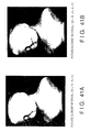
- FIG. 38 and FIG. 39 show adaptive polygon data, which has been obtained from the radial range image of FIG. 37, and which are represented using wire frames.
- FIG. 38A shows adaptive polygon data obtained by integrating the edge map data of the uniform polygon data obtained by resampling the picture element interval to 32 dots and the edge map data of the uniform polygon data obtained by resampling the picture element interval to 16 dots.
- FIG. 38B shows the adaptive polygon data obtained by integrating the integrated edge map data of FIG. 38A and the edge map data of the uniform polygon data obtained by resampling the picture element interval to 8 dots.
- FIG. 39A shows the adaptive polygon data obtained by integrating the integrated edge map data of FIG.
- FIG. 39B shows the adaptive polygon data obtained by integrating the integrated edge map data of FIG. 39A and the edge map data obtained by resampling the picture element interval to 2 dots.
- polygon data with different resolutions are disposed in accordance with the shape of a curved surface.
- step S3480 the N-1 pieces of adaptive polygon data are combined into one piece of data using the format shown in FIG. 35, and the result is stored in memory 3302 as hierarchical adaptive polygon data.
- FIG. 35 shows an example of the data configuration of the hierarchical adaptive polygon data stored in memory 3302.
- vertex data 3531 has an identifier (ID1) added to vertex coordinates (X,Y,Z) of all triangles obtained in step S3460.
- Delimiter 3532 partitions individual data.
- Adaptive polygon data 3533 has resolution 1 and it takes three identifiers of the vertex coordinates as a set to represent one triangle.
- adaptive polygon data 3534 with resolution 2 is a data set and it takes three identifiers of the data on three vertexes constituting a triangle as a set.
- Numeral 3535 is a code, which denotes the end of the hierarchical adaptive polygon data.
- the adaptive polygon data of each hierarchy are stored only by means of the identifiers of vertex coordinates, saving memory capacity.
- the following describes the procedure for displaying hierarchical adaptive polygon data stored in memory 3302, referring to the flowchart of FIG. 36.
- the hierarchical adaptive polygon data stored in memory 3302 as mentioned above are displayed in a 3-D mode according to the processing flow shown in FIG. 36.
- the hierarchical adaptive polygon data is read from the memory 3302 of FIG. 33 (step S3610).
- resolution I is set to an initial resolution (step S3620), and the adaptive polygon data of resolution I is displayed in a 3-D manner (step S3630).
- the initial resolution at this time is the maximum resolution (N-1).
- a resolution which is decided by the technique shown in a step S3660 according to the ratio (angle of view) of the area on a screen occupied by the object to be displayed, may be used. Step S3660 will be discussed later.
- step S3641 through S3645 The event is the information on a moving viewpoint of the observer, whose information is obtained through eyes input device 3305 of FIG. 33, and the event is entered through valuator 3306 or pointing input device 3308. If the entered event is related to the rotation or movement of the object or a change of the viewpoint position (step S3641), then the program proceeds to step S3650.
- step S3650 it is determined whether the rotation or movement is being begun, and if it is being begun, then the resolution immediately before the start is saved before the resolution of an image is decreased by 1 step. Or if it is already in the process of rotation or movement, then the resolution is simply decreased by 1 step.
- step S3660 the angle of visual field, i.e., the angle of view, of a new area for displaying the object, which occupies the visual field of the observer, is estimated. Based on this obtained angle, a value K, which satisfies the conditions shown in step S3661, is determined, and the determined value is set as the current resolution.
- t1 denotes a predetermined interval of the angle of view required for changing the display resolution.
- step S3670 When no more input event is given and the object or viewpoint changes from the rotating or moving state to a quiescent state, the program advances to step S3670. If it is the rotating state immediately before the quiescent state, i.e., J ⁇ 0, then the resolution is set back to resolution J, which is the resolution before the rotating state, and J is reset to 0 (step S3670).
- step S3680 if the new set resolution proves to display polygons, which are so small that they exceed the resolution limit of the display unit, then the resolution is decreased so that none of the polygons go beyond the resolution limit of the display unit (step S3680). Further in step S3690, the new resolution is checked for validity, and another 3-D display of the object is implemented using the adaptive polygon data of the resolution I. More specifically, in step S3690, it is checked whether the set resolution exceeds the minimum resolution or the maximum resolution of the hierarchical adaptive polygon data stored in memory 3302. If the set resolution proves to be lower than the minimum resolution, then it is reset to the minimum resolution, while if it proves to be higher than the maximum resolution, then it is reset to the maximum resolution.
- FIG. 38 and FIG. 39 show 4-stage hierarchical adaptive polygon data displayed using wire frames, the data being obtained by the embodiments.
- FIG. 40 and FIG. 41 show shaded data corresponding to the adaptive polygon data of FIG. 38 and FIG. 39, respectively.
- these hierarchical adaptive polygon data are switched and displayed in accordance with the procedure shown by the flowchart of FIG. 36.
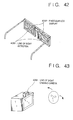
- Eyes detector 4281 may be added near the two lenses of the head mounted display (HMD) shown in FIG. 42 to detect the movement of the eyes, so that the equivalent operation to that of this embodiment can be performed by carrying out the processing of step S3650 of FIG. 36 while the eyes is moving.
- HMD head mounted display
- TV camera 4391 may be mounted on CRT 3304 of FIG.
- step S3650 of FIG. 36 is carried out while the eyes is moving, and further, an approximate distance to a viewpoint is calculated from the distance between the eyes in order to calculate the angle of view, then the processing of step S3660 is carried out. This enables the equivalent operation to that of this embodiment to be accomplished.
- the size of a polygon i.e., resolution
- a partial shape of the object to be displayed thereby preventing generating more polygons than necessary in an attempt to faithfully representing the shape.
- polygon data having a plurality of different resolutions for a single object to be displayed, making it possible to display the object by changing the resolution in response to the instructions given by an observer on rotation, movement, etc.
- the display resolution is decreased to avoid representing unnecessary details of a shape when the observer does not need the representation of the details of the shape while the object is turning or the like, enabling smooth display of a turning or moving object.
- the angle in the visual field occupied by the object when it is displayed by making use of the position or direction of the observer in relation to the display unit and to change the resolution of the display image accordingly.
- the load on the display unit can be reduced by changing the resolution of polygon data according as the object is displayed small or large on the screen.
- the 3-D image displaying method and apparatus described above make it possible to provide 3-D display of an object by changing the resolution in accordance with the display condition, thereby reducing the load applied to the display unit and also ensuring smooth display when a displayed image is moved, enlarged or reduced.
Description
- The present invention relates to an image processing method and apparatus and more particularly to a method and apparatus for processing data defining 3-D geometrical shape using triangular patches.
- There have been suggested a variety of so-called range finders, which are designed to radiate a beam to a target object (an object to be measured) to determine a distance to the object by taking advantage of the beam reflected from the object and by carrying out two-dimensional optical scan over the entire object, thus obtaining the distance information on the object.
- As the methods for measuring a distance to an object, which are employed in the aforesaid range finders, there is a method, wherein an optical pulse is emitted to the object and the distance is determined by measuring the time required for the optical pulse to reflect back from the object, and there is another method, wherein a beam with its intensity modulated into a sine wave is launched into a target object and the distance to the target object is determined by detecting the phase difference between the beam reflected from the object and the original beam. The recent progress in semiconductor lasers and the high-frequency circuit technology has enabled these methods to measure distances with a resolution of 1 mm or less and they are used for measuring the position of an object located at a short distance, identifying an object and the like.
- There has also been proposed a shape measuring apparatus which is designed to emit a beam from a light source to an object via reflecting mirrors, and at this time, the reflecting mirrors are driven by driving means to two-dimensionally scan the object with the beam in order to detect the changes in the optical path length by utilizing the beam reflected from the object, thus measuring the shape of the object (references: OPTOELECTRONICS (1985, No. 12, pp. 59, by Seiji Inokuchi, et al.).
- In the aforesaid shape measuring apparatus, an object to be measured is spatially held or rested. This makes it necessary to have the object undergo two-dimensional optical scanning from restricted directions, presenting a problem in that the rear, top or bottom surface, etc. of the object cannot be measured.
- The image distance information obtained by using the shape measuring apparatus described above is referred to as a range image. More specifically, in the range image, the information on depth and position is stored in each picture element position thereof, while in a variable-density image or color image taken by a typical camera or the like, information on brightness is stored in each picture element position thereof. The range image is normally an image measured from a single direction as in the case of photographing with a camera. Hereinafter, this will be referred to as a projective range image. In contrast to the projective range image, a range image provided with the positional information on full circumference directions of a target object is called a radial range image, the positional information being obtained by performing measurement in full circumference directions of the target object.
- Conventionally, in order to obtain a radial range image, a range finder for measuring a distance along a single vertical line is fixed around an object to be measured or rotated around it by a fixed rotary system, thereby measuring each line. This conventional method, however, is disadvantageous in that a significantly larger measuring apparatus structure than an object to be measured is required, and the apparatus is hard to move toward the object, leading to poor mobility and high cost.
- There are also the following conventional methods available to obtain range images or generate approximate shape data.
- (1) A stereoscopic image of a 3-D space such as an indoor scene or a 3-D object can be obtained by photographing them by two cameras, which are installed in parallel with an appropriate distance provided between them, or by moving a single camera in parallel to photograph them twice so that a left image and a right image constituting a stereo image may be obtained. From this stereo image, a 3-D position can be determined according to the principle of triangulation by designating identical points in an actual 3-D space in the right and left images automatically, semi-automatically or manually. By repeating this operation many times, the positions of points in an actual 3-D space can be determined in a 3-D manner.
- (2) There is a method available, whereby a range image of a 3-D space such as an indoor scene similar to the one above or a 3-D object can be entered by means of a range imaging apparatus. It is also possible to select an image point from this range image according to some characteristic amount.
- (3) It is also possible to enter in order the positions of 3-D points on the surface of a 3-D object by means of a contact or non-contact type 3-D digitizer.
- (4) When there are many groups of points, there are methods available, whereby a Delaunay triangulation net is generated using the groups of points as generating points to determine triangles having the points as the vertexes thereof. In one of the methods, points are added one by one to update the Delaunay triangulation net. This method will be described below.
-
- In a Delaunay triangulation net shown in FIG. 12A, when a point marked with x in FIG. 12B is designated, a triangle wherein this point lies in a circumcircle is looked for. When there are three vertexes pj = (xj, yj), pk = (xk, yk), and pl = (xl, yl) of an element triangle in the Delaunay triangulation net, and a determinant shown below is employed for determining whether or not a point p (= (x, y)) to be added is in the circumcircle;

- if, p is a point on a circle, which passes pj, pk, and pl if H(pj,pk,pl,p) = 0, or
- p is a point in a circle, which passes pj, pk, and pl if H(pj,pk,pl,p) < 0, or
- p is a point outside a circle, which passes pj, pk, and pl if H(pj,pk,pl,p) > 0.
-
- This makes it possible to determine whether the point to be added lies in a circumcircle of the triangle. After making this determination on all triangles, all the triangles, which include the point to be added in the circumcircles, are combined into one area (FIG. 12C). The triangles in this area are deleted, then using the designated point as a vertex, new triangles are generated using two adjoining vertexes of the contour of this area (FIG. 13), and the new triangles are inserted in the area (FIG. 12D).
- The prior art (1), (2) or (3) discussed above makes it possible to acquire point positions in a 3-D space such as in an indoor scene or a 3-D object. To restore, however, the 3-D shape of a 3-D space such as in an indoor scene or of a 3-D object, the point positions alone are not sufficient; it is necessary to determine a surface constituted by the points. This was the problem with the prior arts. It was considered possible to generate a Delaunay triangulation net to generate a 3-D geometrical shape based on triangular patches by combining the prior art (4) with the prior arts described above, however, there was no technology available to combine them.
- Even if it were possible to combine the prior art (1), (2) or (3) with the prior art (4) and to generate the Delaunay triangulation net, thereby generating the 3-D geometrical shape based on the triangular patches, then the prior art (4) would make it possible to update the triangular patches by updating the Delaunay triangulation net by adding the generating points one after another. If, however, a point is not designated in a correct position, then it is necessary to delete the generating point and update the triangular patches. This was not possible with the prior arts.
- There was another problem in addition to the problem described above. When a triangular patch is generated from points by the Delaunay triangulation net, the edges of the triangle are automatically decided according to the principle of Delaunay (the circumcircle principle and the minimal angle maximum principle). There is a need, however, for keeping a line, which connects two given points, as a edge of the triangulation net to be generated, and this need cannot be satisfied.
- The following describes a prior art, whereby range image data are obtained, then a resultant image is reproduced and displayed.
- Technologies for displaying 3-D images by computer graphics have been developed. The techniques in such image displaying technologies include:
- (1) a technique, whereby a shape of an object is described using square lattices fixed equidistantly on a range image to provide the 3-D display;
- (2) a technique, whereby adaptive polygon patches, in which the size of polygons are changed in accordance with the curvature of local shape of a curved surface of an object to be displayed, are generated from range image data to describe the shape of the object by the polygon data, thereby providing the 3-D display;
- (3) a technique, whereby equidistant square lattices are generated from the shape data of curved surfaces described by a shape modeler to describe the shape of an object, thereby providing the 3-D display; and
- (4) a technique, whereby an object is described by an appropriate polygon by a shape modeler to directly use it for the 3-D display.
-
- In the techniques of (1) and (3), however, the shape of the object is described by polygons which have same size; therefore, smaller polygons must be used to represent a complicated surface shape. If, however, more polygons are used, then more than necessary polygons would be used for a uniform surface shape such as a large plane. This results in significant waste in memories used and also it causes other problems, including slow displaying speed.
- Likewise, in the techniques of (2) and (4), the size of the polygon is changed in accordance with the surface shape of an object to be displayed; therefore, these techniques are free from the problem with the aforesaid techniques, which use polygons which have same size to represent a shape. Nevertheless, all the four techniques discussed above unavoidably represent details according to shape data even when an observer does not need any detailed shape of the object as in a case, where the observer moves or rotates the object to be displayed. As a result, more load than necessary is applied to a display unit, preventing smooth rotation or movement required by the observer.
- In addition, even when the observer does not rotate or move the object, the above techniques attempt to display the details of the shape of the object regardless of the resolution of the display unit or the resolution of the observer's vision even when the object occupies only a small portion of a display screen, i.e., even when the angle of view is small, because of a viewpoint set by the observer. This applies more load than necessary to the display unit.
- "A Multi-Resolution Surface Model for Compact Representation of Range Images" by Soucy et al in Proc. 1992 IEEE International Conference on Robotics and Automation, Los Alamitos, CA, US, XP 000299955 describes a surface triangulation technique for surface description at different levels of resolution in a range image. An iterative approach is used to obtain a desired level of approximation error.
- "Consideration on Automatic Acquisition and Reconstruction of an Object Shape" by Nishino et al in Signal Processing of HDTV, 1988, Amsterdam, NL, pages 295-302, XP 000075065 discloses a slit-ray projection method to obtain range data of an object, in which the object is modelled using triangular patches.
- "An On-Line Algorithm for Constrained Delaunay Triangulation" by De Floriani et al in Graphical Models and Image Processing, vol., 54, no. 4, July 1992, Duluth, MN, GB, pages 290-300, XP 000288355 discloses an algorithm for constrained Delaunay triangulation that is based on the stepwise refinement of an existing triangulation by the incremental insertion of points and constraint segments.
- It is an object of the present invention to provide a method and apparatus for image processing, which solve one or more of the above problems.
- According to the present invention, there is provided an image processing apparatus as set out in
claim 1. - The present invention also provides an image processing method as set out in
claim 13. - Optional features are set out in the other claims.
- FIG. 1 is a schematic configuration diagram of a shape measuring apparatus of a first reference system;
- FIG. 2 is an enlarged explanatory view of a part from FIG. 1;
- FIG. 3A is an explanatory view of a major section of a supporting mechanism for an object to be measured;
- FIG. 3B is an explanatory view of a part taken on line A-A in FIG. 3A;
- FIG. 4A is an explanatory view of an appearance of a geodetic dome;
- FIG. 4B is an explanatory view of a development of the geodetic dome shown in FIG. 4A;
- FIG. 5 is a block diagram showing a basic configuration of a radial range image measuring apparatus according to a second reference system;
- FIG. 6 illustrates the flow of a process for calibrating a rotation axis of a turntable; of which process is one of processes of a method for obtaining a radial range image according to the second reference system;
- FIG. 7 illustrates a flow of a process for calibrating the rotation axis of the turntable, which is one of the processes of the method for obtaining a radial range image according to the second reference system;
- FIG. 8 illustrates the flow of a process for determining actual coordinates of an object; of which process is one of the processes of the method for obtaining a radial range image of the second reference system;
- FIG. 9 is a conceptual view of radial range image processing;
- FIG. 10 illustrates an example of the radial range image obtained in the second reference system;
- FIG. 11 is a conceptual view illustrating a process for determining an equation for the rotation axis of the turntable;
- FIGs. 12A - 12D are schematic diagrams illustrating the flow of the processing for adding a generating point to a Delaunay triangulation net, and for updating generating points accordingly;
- FIG. 13 is a schematic diagram illustrating a processing carried out when a generating point is added to the Delaunay triangulation net;
- FIG. 14 is a block diagram of a triangular patch generator according to a third reference system;
- FIG. 15 is a flowchart illustrating an entire flow of a triangular patch generating process according to the third reference system;
- FIG. 16 is a flowchart of designating a corresponding by means of a mouse in FIG. 15;
- FIG. 17 is a flowchart of a process for adding the generating point shown in FIG. 16;
- FIG. 18 is a flowchart of deleting the generating point shown in FIG. 16;
- FIGs. 19A - 19F are schematic diagrams illustrating a generating point deleting process;
- FIG. 20 is a flowchart of generating the Delaunay triangulation net using a vertex of the polygonal area C shown in FIG. 18;
- FIG. 21 is a flowchart of deleting a triangle lying outside polygonal area C shown in FIG. 18;
- FIGs. 22A - 22F illustrate an example of a triangle generating process for generating a triangle outside polygonal area C;
- FIG. 23 illustrates an example of an entered stereo image;
- FIG. 24 illustrates an example of a state, wherein a system is waiting for a point to be designated in an image;
- FIG. 25 illustrates an example, wherein a generating point has been added to the Delaunay triangulation net, which has accordingly been updated;
- FIG. 26 illustrates an example, wherein a generating point has been deleted from the Delaunay triangulation net, which has accordingly been updated;
- FIG. 27 shows a flowchart of a process for designating a point by means of a mouse in a fourth reference system;
- FIG. 28 shows a flowchart of a process for fixing a line in the fourth reference system;
- FIGs. 29A - 29G are schematic diagrams of the process for fixing the line in the fourth reference system;
- FIG. 30 is a flowchart of a process for selecting a triangle, which involves a line segment shown in FIG. 28;
- FIG. 31 shows an example of a state, wherein the system is waiting for a point to be designated in an image in a Delaunay triangulation net in the fourth reference system;
- FIG. 32 is an example, wherein the line segment connecting two generating points is fixed as an edge in the fourth reference system;
- FIG. 33 is a block diagram showing a configuration of a 3-D display unit of an embodiment according to the present invention;
- FIG. 34 is a flowchart illustrating a processing flow for creating hierarchical adaptive polygon data of an embodiment according to the present invention;
- FIG. 35 is a data format of the hierarchical adaptive polygon data of an embodiment according to the present invention;
- FIG. 36 is a flowchart illustrating a processing flow of displaying the hierarchical adaptive polygon data of an embodiment according to the present invention;
- FIG. 37 shows a radial range image used for an experiment in an embodiment according to the present invention;
- FIGs. 38A and 38B show hierarchical adaptive polygon data prepared in an embodiment according to the present invention, the data being displayed in a 3-D manner using wire frames;
- FIGs. 39A and 39B show hierarchical adaptive polygon data prepared in an embodiment according to the present invention, the data being displayed in a 3-D manner using wire frames;
- FIGs. 40A and 40B show hierarchical adaptive polygon data shown in FIG. 38, the data being shaded and displayed in a 3-D manner;
- FIGs. 41A and 41B show hierarchical adaptive polygon data shown in FIG. 39, the data being shaded and displayed in a 3-D manner;
- FIG. 42 shows the appearance of eyes input head-mounted display (HMD); and
- FIG. 43 shows another example of the eyes input apparatus.
-
- A shape measuring unit constituting a part of an image processing apparatus of a first reference system is designed so that, when it holds an object to be measured (hereinafter referred to as "target object") in a capsule made of a light-transmitting material by means of supporting members and radiates a beam from a light source provided outside the capsule to the target object via the capsule, it relatively moves the capsule with respect to an incident direction of the beam by a driving means provided on the capsule to change the beam radiating positions on the target object and it detects the beam reflected from the target object by a detecting means, thereby measuring the shape of the target object by utilizing a signal received from the detecting means.
- FIG. 1 is the schematic diagram showing the configuration of the first reference system, and FIG. 2 is the enlarged explanatory drawing of a part of FIG. 1. In the drawings, a
laser oscillator 1 serves as a light source and it emits laser beams. Anoptical modulator 2 modulates the intensity of a laser beam received from thelaser oscillator 1. Anoscillator 3 drives theoptical modulator 2. Abeam splitter 4 divides the modulated laser beam into reference light La and measurement light Lb. Aphotodiode 9 detects the intensity of the reference light La provided by thebeam splitter 4. A reflectingmember 5 has an aperture 5A (see FIG. 2) at the center thereof. The measurement light Lb from thebeam splitter 4 is launched into atarget object 6 through theaperture 5a of the reflectingmember 5. Thetarget object 6 is held in aspherical capsule 7 made of a light-transmitting material, e.g., glass.Motors capsule 7. Acondenser lens 8 converges the measurement light Lb, which reflects off thetarget object 6 and then reflects from the reflectingmember 5, and leads it into aphotodiode 10. Thephotodiode 10 detects the intensity of the measurement light Lb based on the beam reflected from thetarget object 6 as it will be discussed later. Aphase measuring unit 11 determines a phase difference between the reference light La and the measurement light Lb detected respectively by thephotodiodes information processor 12 controls the driving means 16, changes the incident position of the measurement light Lb launched into thetarget object 6, and determines, by computation, a shape of thetarget object 6 from a difference in light path according to a signal received from thephase measuring unit 11 for each incident position of the measurement light Lb. - In this system, with the configuration described above, the intensity of the laser beam from the
laser oscillator 1 is modulated by means of theoptical modulator 2 and the laser beam is divided through thebeam splitter 4 into two beams; one for the reference light La and the other for the measurement light Lb. The reference light Lb from thebeam splitter 4 passes through theaperture 5a of the reflectingmember 5 and irradiates apoint 6a of thetarget object 6 via thecapsule 7 as shown in FIG. 2. The beam, which has been reflected and scattered from thetarget object 6, passes through thecapsule 7 again before it enters the reflectingmember 5. The beam reflected from the reflectingmember 5 is led into thephotodiode 10 via thecondenser lens 8. The reference light Lb provided by thebeam splitter 4 is launched into thephotodiode 9. - The
phase measuring unit 11 measures the phase difference between the reference light La and the measurement light Lb launched respectively into thephotodiodes information processor 12. Theinformation processor 12 determines the difference in optical path between the reference light La and the measurement light Lb from the information on the phase difference and a modulated frequency supplied by theoptical modulator 2. The driving means 16 moves thecapsule 7 in a predetermined direction, which will be discussed later, so that the beam is launched into the target object from all directions. The difference in optical path is determined on every direction of the target object and the shape of the target object is determined in accordance with a publicly known method. - FIG. 3A is the explanatory view of the major section of a supporting mechanism of the
target object 6 in this system and FIG. 3B is the explanatory view of a part taken on line A-A. In these drawings, numeral 15a denotes a threaded hole provided in thecapsule 7 and numeral 15b denotes a screw, i.e., the supporting member, which is screwed into the threaded hole. In this system, thetarget object 6 is supported at four points with the supportingmembers 15b. Thetarget object 6 housed in thecapsule 7 is fixed approximately at the center of thecapsule 7 by adjusting the lengths of the supportingmembers 15b projecting into thecapsule 7. After fixing the object, the portions of the supporting members extending outside thecapsule 7 are cut off. - FIG. 4A and FIG. 4B are the explanatory view showing the data structure of the geodetic dome for determining the rotational direction and rotational angle of the
capsule 7 driven by the driving means of FIG. 1. FIG. 4A shows the appearance of the geodetic dome and FIG. 4B shows the development thereof. - To measure the target object from all directions with a uniform density, the
information processor 12 calculates the latitude or longitude of each vertex of the geodetic dome shown in FIG. 4 and controls the drive of themotors capsule 7. - At this time, the relationship between the position of a vertex (i,j,k) and the latitude/longitude (/) is expressed aswhere k = 2π/5, t = atan (2), 0 ≤ ≤ π,0 ≤ ≤ 2π. (C. H. Chen and A.C. Kak, "A robot vision system for recognizing 3-D object in low-order polynomial time, "IEEE Transaction on Systems, Man and Cybernetics, Vol.19 No.6, pp. 1535-1563, 1989).

- The shape of
object 6 at the contacted portion, where the supportingmember 15b is in contact with thetarget object 6, is interpolated from a neighborhood value. - This system is configured so that the
target object 6 is housed in thespherical capsule 7, which is rotated according to the rotational direction and the rotational angle determined from the geodetic dome shown in FIG. 4 with respect to the incident direction of the beam from the light source, thereby optically scanning the target object, however, the configuration is not limited to this; it may alternatively be configured as follows: - (1) The target object is housed in a transparent capsule shaped in a rectangular parallelepiped, and the capsule is rotated so that the beam from the light source always strikes each surface of the rectangular parallelepiped at an angle of 90 degrees, thereby measuring the shape thereof by optically scanning the target object in a 2-D manner.
- (2) The target object is housed in a transparent capsule shaped in a rectangular parallelepiped, and the capsule is rotated while maintaining the 90-degree angle between the beam of the incident light source and the surface of the rectangular parallelepiped and repeatedly exposed to a 2-D pattern light or slit light, thereby measuring the object's shape.
- (3) The target object is housed in a spherical, transparent capsule, which is rotated and exposed to the 2-D pattern light or slit light a few times to measure the shape thereof.
-
- In this system,
capsule 7 needs not be necessarily sealed hermetically as long as it encloses the target object and it can be rotated at a desired angle by the driving means. In addition, thecapsule 7 needs not necessarily transmit the beam uniformly from all directions. - Thus, the shape measuring apparatus is capable of measuring the shape in every direction with high accuracy by configuring the shape measuring apparatus as described above when optically scanning the target object to measure the shape thereof.
- An outline of the method and the configuration of an apparatus for obtaining the radial range image according to a second reference system will be given first, then detailed explanation will follow. The method for obtaining the radial range image according to the second reference system includes a step of generating depth data for calibration, wherein an object for calibration is disposed at a plurality of different rotational angles around the rotation axis and the depth of the object for calibration is measured for each rotational angle in order to generate the depth data for calibration, a step of calculating the rotation axis, wherein the positional data on the rotation axis, which rotates the object for calibration, are calculated from the depth data for calibration, a rotation step, wherein the target object is rotated around the rotation axis by a predetermined rotational angle, a step of generating depth data, wherein the depth data are generated by measuring the depth of the target object for each predetermined rotational angle, and a step of calculating actual coordinates, wherein the coordinates of the target object in actual space are measured by applying the depth data and the positional data of the rotation axis.
- The apparatus for obtaining the radial range image includes a depth data generating means, whereby an object for calibration is disposed at a plurality of different rotational angles around the rotation axis and the depth of the object for calibration is measured for each rotational angle in order to generate the depth data for calibration, a means for calculating the rotation axis, whereby the positional data on the rotation axis, which rotates the object for calibration, are calculated from the depth data for calibration, a rotating means, whereby the target object is rotated around the rotation axis by a predetermined rotational angle, a depth data generating means, whereby the depth data are generated by measuring the depth of the target object for each predetermined rotational angle, and a means for calculating actual coordinates, whereby the coordinates of the target object in actual space are measured by applying the depth data and the positional data on the rotation axis.
- In the configuration described above, the method for obtaining the radial range image is designed to dispose the object for calibration at a plurality of different rotational angles, measure the depth of the object for calibration for each rotational angle to generate the depth data, calculate the positional data on the rotation axis, around which the object for calibration is rotated, from the depth data, rotate the target object by the predetermined rotational angle, measure the depth for each line to the target object for each predetermined rotational angle to generate depth data, and calculate the coordinates of the depth data in actual space by applying the positional data on the rotation axis.
- Likewise, in the apparatus as another reference system for obtaining the radial range image, a means for generating depth data for calibration disposes the object for calibration at a plurality of different rotational angles, measures the depth of the object for calibration for each rotational angle, and generates depth data, a means for calculating the rotation axis calculates the positional data on the rotation axis, around which rotates the object for calibration is rotated, from the depth data, a rotating means rotates the target object by the predetermined rotational angle, a depth data generating means measures the depth for one line of the target object for each predetermined rotational angle to generate the depth data, and the means for calculating actual coordinates calculates the coordinates of the depth data in actual space by applying the positional data of the rotation axis.
- The reference systems will now be explained in detail.
- FIG. 5 shows the basic configuration of the apparatus for obtaining the radial range image. In FIG. 5, the apparatus for obtaining the radial range image is roughly divided into
image processing system 120 andimage measuring system 121. Theimage measuring system 121 obtains projective range image data and radial range image data from a target object and processes the data before sending them to theimage processing system 120.Image processing system 120 employs the received projective range image data, the received radial range image data or the like to calculate the position of aturntable 109, performing arithmetic operation for determining the actual coordinates in actual space, which correspond to the radial range image data, modulating the luminance of the range images to display them on awindow system 104, or performing other image processing. - The following describes the configuration of
image processing system 120.CPU A 101 executes data processing, arithmetic operation, and data receiving by processing programs stored beforehand inmemory A 102.Memory B 103 saves data to be processed. Thewindow system 104 is the display system, which displays processes and results of processing.Keyboard 105 is used to enter user's instructions or data. Pointing device 106 is used to enter user's instructions throughwindow system 104.Bus 111 is data transmission lines for data transferred to and from the devices mentioned above.Memory B 103 stores projective range image data d1 and radial range image d3 obtained by rangeimage measuring apparatus 110, and measurement point position data d2, which is obtained by executing the rotation axis calibration program and the rotational geometrical transformation program stored beforehand in thememory A 102. Data receiving program p1 stored beforehand inmemory A 102 controlsnetwork controller A 140 to receive and store the data obtained by the rangeimage measuring apparatus 110 inmemory B 103 viabus B 112,network controller B 141, and network lines 113. - The configuration of
image measuring system 121 will now be described.CPU B 107 controls rangeimage measuring apparatus 110 andturntable 109. Range image measuring apparatus control program p4 for controlling rangeimage measuring apparatus 110 to obtain range image data, turntable control program p5 for controllingturntable 109, on which a target object is rested, and data transfer program p6 for transferring measurement data tomemory B 103 are stored beforehand in amemory C 108. These programs are read by theCPU B 107 to execute various types of processing. The rotational angle ofturntable 109, whereon the target object is rested, is controlled by theCPU B 107. Projective rangeimage measuring apparatus 110 obtains depth information by projecting light to the target object and receiving the reflected light, which is controlled by theCPU B 107.Bus B 112 is used for data transmission among the devices.Network lines 113 is an interface connectingbus A 111 and thebus B 112, the data transmission through the interface being controlled bynetwork controller A 113 andnetwork controller B 141. - FIG. 6, FIG. 7, and FIG. 8 illustrate the processing flows for obtaining a radial range image. More specifically, FIG. 6 and FIG. 7 shows the processing flows of the method for determining the rotation axis of
turntable 109, while FIG. 8 shows the processing flow for the measurement of the object by applying the determined rotation axis to the acquisition of the radial range image. - First, the processing for determining the rotation axis will be explained in detail with reference to the processing flowcharts given in FIG. 6 and FIG. 7. Steps S201, S202, S204, and S205 are implemented in
image measuring system 121, while other steps are implemented inimage processing system 120. - In step S201, an object for calibration, which has at least two planes, such as a quadrangular prism and triangular prism, is placed on
turntable 109 with its bottom surface down. At this time, the angle formed by the two planes may be unknown. The accurate size of the object for calibration may be unknown as long as the size is appropriate for the turntable and the measuring apparatus. - In step S202, range image measuring apparatus control program p4 controls range
image measuring apparatus 110 to set a predetermined rotational angle, whereat the two planes can be measured simultaneously, thereby performing the projective range image measurement on the object for calibration. Data transfer program p6 controlsnetwork controller B 141 and sends the obtained projective range image measurement data toimage processing system 120 to trigger the processing of step S203.Image processing system 120 stores the entered projective range image measurement data in area d1 ofmemory B 103, andimage processing system 120 begins the processing from step S203.Image measuring system 121 executes the processing, which begins with the step S204. - In step S203, two plane areas are cut out from the projective range image data stored in area d1 of
memory B 103. This processing is accomplished by finding the closest line from measurements by taking advantage of the already known fact that the target object has two planes, which are convexly connected, facing against the measuring apparatus. The image is cut into two areas with the line, and the surrounding edges of the cut areas are deleted. The deletion of the edge portions is necessary because the data on the surrounding edges are usually unstable. - In step S207, a plane approximation calculation is carried out by applying the information on the surface position of each picture element in the obtained left plane area. This is accomplished by applying the data in the formula (1) for the plane to determine the estimated values of coefficients a, b, c and d.
- The plane formula for the left plane area of the first measurement image thus obtained is hereinafter referred to as plane formula (1.1L).
- In step S208, a plane approximation calculation is performed by using the information on the surface position of each picture element in the obtained right plane area. This is accomplished by applying the data in the formula (1) for the plane to determine the estimated values of coefficients a, b, c, and d in the same manner as in step S207. The plane formula for the right plane area of the first measurement image thus obtained is hereinafter referred to as plane formula (1.1R).
- In step S220, the system waits for the second measurement data sent from the image measuring system. When the second measurement data is received, the data is stored in area d1 of
memory B 103. The program then proceeds to step S206. The processing performed in the steps S206, S209, and S210 is basically the same as that carried out in steps S203, S207, and S208 with only difference of whether the image data received first or second is processed. - In step S206, two plane areas are cut out according to the projective range image data received second, which is stored in area d1 of
memory B 103. In step S209, the plane approximation calculation is carried out by applying the information on the surface position of each picture element in the obtained left plane area. This is accomplished by applying the data to the formula (1) for the plane to determine the estimated values of coefficients a, b, c, and d. - The plane formula for the left plane area of the second measurement image thus obtained is hereinafter referred to as plane formula (1.2L).
- In step S210, the plane approximation calculation is performed by employing the information on the surface position of each picture element in the obtained right plane area. This is accomplished by applying the data to the formula (1) for the plane to determine the estimated values of coefficients a, b, c, and d in the same manner as in the step S209. The plane formula for the right plane area of the second measurement image thus obtained is hereinafter referred to as plane formula (1.2R).
- In step S211, a plane is determined which passes an intersection line of the plane formula (1.1L) and the plane formula (1.2L), and also bisects the angle between the plane based on formula (1.1L) and the plane based on formula (1.2L). The obtained plane is referred to as a plane formula (1.3). In a step S212, a plane is determined which passes an intersection line of the plane formula (1.1R) and the plane formula (1.2R), and also bisects the plane based on formula (1.1R) and the plane based on formula (1.2R). The obtained plane is referred to as a plane formula (1.4).
- In step S213, the intersection line of the plane formula (1.3) and the plane formula (1.4) is calculated. A linear formula for the intersection line thus obtained is:
- This provides a linear equation for the rotation axis of the turntable.
- The steps described above are schematically illustrated in FIG. 11.
- The flow of processing, wherein the object is rotated by
turntable 109 having the determined rotation axis and the information on the shape in all circumferential directions is obtained, will now be described with reference to FIG. 8. The processing of steps S303 and S307 is carried out byimage processing system 120, while other steps are carried out by theimage measuring system 121. - In step S301, an object to be measured is rested on the turntable. The rotational angle is regarded as zero degree. In step S302, the range image for each line is measured by
range imaging apparatus 110. This measurement can be accomplished by swinging a polygon mirror once when a range image measuring apparatus based on scanning by means of a laser-beam polygon mirror is used. The obtained distance data is transferred toimage processing system 120 vianetwork controller A 141 and stored in area d3 ofmemory B 103. - Referring to FIG. 9, the concept of the measurement of the radial range image will be described. FIG. 9 shows the contour of
object 942 placed onturntable 109. The distance is measured while rotatingobject 942 aroundrotation axis 941. For each rotational angle, the distance for each line in the direction of the Z axis is measured, and the measurement results are entered in 2-D data table 943 shown in FIG. 9. The range image data of the 2-D data table are stored in d3 ofmemory B 103. The axis of abscissa of 2-D data table 943 denotes the rotational angle ofturntable 109, while the axis of ordinate denotes the height of the rotation axis, i.e., measurement in the direction of the Z axis. The range image data on one point ofobject 942 are stored in each unit of the matrix of 2-D data table 943. - Referring back to the processing flow shown in FIG. 4, the description will be continued.
- In step S303, the obtained measurement points are subjected to geometrical transformation. The obtained range image data on the measurement points are the results of the measurements made as the object was rotated by the turntable. The coordinates in actual space can be obtained by carrying out the rotational geometric transformation, which sets the measurement points back to their original positions before the rotation. This processing allows the proper surface position of the object to be obtained. When an apparent measurement point position is taken as (x,y,z), the total rotation angle as -, and the proper object surface position as (x', y', z'), the rotation geometrical transformation with respect to the rotation axis of formula (2) is expressed by the following formula:

- Since the rotational angle of
turntable 109 is zero degree for the first one-line measurement, the measurement of the points on the one line means direct measurement of the position on the surface of the object. - In step S307, the point position data of each line obtained in step S303 are stored in area d3 of
memory B 103 ofimage processing system 120. In step S304, the turntable is rotated by a minute angle. In step S305, the total sum of the minute rotational angles of the turntable rotated in step S304 is calculated. - In step S306, it is checked whether the total sum of the minute turns has reached a full one rotation; if not, the program goes back to step S302 to repeat the measurement, and if it has reached the full one rotation, then the measurement will be terminated.
- According to the procedure described above, the measurement of the range image of the object from all directions can be achieved.
- FIG. 10 shows an obtained range image of the object with the luminance modulated, the image being displayed on
window system 104. - In this system, an example, wherein the projective range image measuring apparatus and the turntable, which is independent from the apparatus and which allows the rotational angle to be controlled, were prepared to obtain the radial range image, however, the range image measuring apparatus (hereinafter referred to as the measuring apparatus 110), which uses a light-receiving surface element as in the slit light projection method or a pattern light projection method, may alternatively be used as the projective range image measuring apparatus. To use this
measuring apparatus 110 in this system, the measurement of the points on one line in step S302 of FIG. 6 is replaced by the one-line data obtained by measuringapparatus 110. - As explained above, the system provides the following effects. The data on a radial range image, which covers the shape data from every direction around the target object, can be easily generated at low cost without using a measuring apparatus, which is extremely larger than the target object or using a large-scale measuring apparatus, which turns itself. Moreover, the radial range image data can be obtained by setting the target object and automatically measuring the position of the rotation axis, around which the object is rotated, thus permitting easy measurement.
- Therefore, the position of the target object can be set freely and the measurement of the radial range image can be performed at low cost.
- An outline of an image processing method in a third reference system, for obtaining an range image and generating approximate shape data will be given first, then detailed explanation will follow.
- The image processing method of the third reference system includes a step for interactively selecting and entering discrete points on an object in 3-D space and a step for generating a model having a 3-D geometrical shape by employing triangular patches, which apply the Delaunay triangulation net in accordance with the points entered in an input step.
- An image processing apparatus according to the third reference system is equipped with an input means for interactively selecting and entering discrete points on the object in 3-D space and a generating means for generating a model having a 3-D geometrical shape by employing triangular patches, which apply the Delaunay triangulation net in accordance with the points entered through the input means.
- The discrete points of the object in 3-D space are interactively selected and entered through such steps or such a configuration according to the third reference system. Then, based on the entered points, a model having a 3-D geometrical shape is generated by triangular patches using the Delaunay triangulation net.
- The third reference system will be explained in detail.
- FIG. 15 shows the processing flow of the triangular patch generating method of this system.
- FIG. 14 is the block diagram showing an apparatus, which implements the method. The following gives detailed explanation of the processing carried out by
CPU 1403 of the system, which functions as a processing unit, a related processing procedure (program) being stored inmemory 1401. - A stereo image, which has been obtained by photographing an object with two cameras spaced away from each other with a certain distance or by photographing the object twice with a single camera moved to provide perspective, is read in step S301 through I/
O unit 1405 for an external equipment in FIG. 14, and the stereo image, which has been read, is stored in areas ddl and dd2 ofmemory 1402. With the stereo image displayed ondisplay unit 1404, a Delaunay triangulation net is updated by designating the corresponding points of the right and left images, respectively, by means of mouse 1407 or other pointing device (step S302). The processing in step S302 (program routines rr1 through rr3 stored in memory 1401) will be discussed later with reference to the flowchart. Designating the corresponding points is repeated until it is terminated in step S303. If termination is designated, then all element-triangles of the Delaunay triangulation net are transformed, in step S304, to triangular patch data, which is output through I/O unit 1405. - The processing in aforesaid step S302 will now be described in accordance with the flowchart given in FIG. 16. The processing includes designating of the points by means of the mouse and updating the Delaunay triangulation net.
- In step S401, the system waits for an input given through a mouse used for designating a point. If no instruction is given in step S402 as to whether the system should exit the waiting for an input, then a new generating point is designated in step S403 or a generating point to be deleted is designated in step S405. The generating point designated in step S403 is added to the Delaunay triangulation net in step S404. The processing will be discussed later with reference to the flowchart shown in FIG. 17. This processing is the same as that discussed earlier.
- The generating point designated in step S405 is deleted from the Delaunay triangulation net in a step S406. This processing will be discussed later with reference to the flowchart shown in FIG. 18.
- The processing of adding the generating point in step S404 will now be described, referring to FIG.17. First, in step S501, an element triangle in the Delaunay triangulation net is checked to determine whether the point to be added lies inside a circumcircle in order to decide which element triangle of the current Delaunay triangulation net should be updated, and the triangle, which includes the point to be added inside the circumcircle, is registered (step S502). This processing is carried out on all triangles (step S503). These steps S501 through S503 correspond to FIG. 12C. Whether a certain point is located inside the circumcircle of a triangle can be determined as shown below. If the three vertexes of the triangle are taken as pj = (xj, yj), pk = (xk, yk), and pl = (xl, yl), and the determinant shown below is employed for a point p = (x, y);

- then, p is a point on a circle, which passes pj, pk, and pl when H(pj,pk,pl,p) = 0, or
- p is a point in a circle, which passes pj, pk, and pl when H(pj,pk,pl,p) < 0, or
- p is a point outside a circle, which passes pj, pk, and pl when H(pj,pk,pl,p) > 0.
-
- Thus, all triangles that include the point to be added inside circumcircles have been selected. The selected triangles are combined into a single polygonal area A (step S504). Then, the triangles in this polygonal area A are deleted (step S505), and triangles, which are formed by applying two adjoining vertexes on the contour line of polygonal area A and the point to be added, are named triangle group B (step S506). These steps S504 through S506 correspond to FIG. 13. After that, polygonal area A in the original Delaunay triangulation net is replaced by triangle group B to generate a new Delaunay triangulation net (step S507). The Delaunay triangulation net is updated in steps S501 through S507. Thus, the Delaunay triangulation net shown in FIG. 12A is updated to the Delaunay triangulation net shown in FIG. 12D.
- The processing in step S406 for deleting the generating point mentioned previously will now be described with reference to the flowchart of FIG. 18 and FIG. 19.
- Select triangles, which have the designated generating point to be deleted (FIG. 19A) as a middle point thereof (step S601). This selection results in a hatched section shown in FIG. 19B. This triangle group is named as polygonal area C (step S602), then the triangles in this polygonal area C are deleted (step S603). This eliminates the generating point designated to be deleted and also the triangles involving the generating point. At this point, there is no triangulation net in polygonal area C; therefore, processing for regenerating a triangulation net will be carried out as follows. Applying the vertexes of the polygon of polygonal area C as generating points, a Delaunay triangulation net, which is entirely different from the previous Delaunay triangulation net, is generated (step S604). The processing for generating the Delaunay triangulation net in step S604 will be discussed later in connection with the flowchart shown in FIG. 20. The Delaunay triangulation net obtained in step S604 may have a triangle outside polygonal area C (an example is shown in FIG. 22A - 22F); therefore, the triangle, which lies in the Delaunay triangulation net generated in step S604 but which has been generated outside polygonal area C is deleted in step S605. Step S605 will be discussed later with reference to the flowchart of FIG. 21. The triangle group thus obtained replaces polygonal area C in step S606 to delete the generating point and update the Delaunay triangulation net. It can be mathematically proved that the method for updating the Delaunay triangulation net in steps S601 through 606 maintains characteristics of the Delaunay triangulation net.
- The processing for generating the Delaunay triangulation net using the vertexes of polygonal area C in step S604 will now be explained according to FIG. 20.
- First, one of the vertexes of the polygon is selected (step S801) and the generating point designated in FIG. 13 is added in step S802. These steps S801 and S802 are carried out on all vertexes (step S803) to generate the Delaunay triangulation net applying the vertexes of polygonal area C.
- The procedure for deleting the triangle outside polygonal area C from the Delaunay triangulation net in step S605 will be explained, referring to FIG. 21. An example of this processing illustrated in FIG. 22A - 22F will be used for the explanation.
- First, a clockwise circulation list of the vertexes is generated along the contour of polygonal area C (step S901, FIG. 22D). Then, for each triangle of the Delaunay triangulation net, a clockwise circulation list of the vertexes is generated (step S902, FIG. 22E). If any of the triangles is located outside polygonal area C, then the triangles share the vertex, which has the opposite list direction as shown in FIG. 22F. Therefore, in step S903, it is checked whether the list directions are reversed and if any reversed list direction is found, the triangle having the opposite list direction is deleted from the triangle group (FIG. 22F). The processing of steps S903 and S904 is carried out on all triangles (step S905) to delete triangles lying outside polygonal area C.
- An example of the process for generating a triangular patch data from a stereo image according to the method described above is illustrated in FIG. 23 through FIG. 26. FIG. 23 shows the stereo image read in step S301. FIG. 24 shows a state, wherein designation is performed by means of the mouse in step S302 and it is the state, wherein the system is waiting for an input in the step S401. FIG. 25 shows a result of designating a new point in step S403 from the state shown in FIG. 24 and adding the generating point in the step S404 (point P in FIG. 25). FIG. 26 shows a result of designating a generating point to be deleted in the step S405 from the state shown in FIG. 25 and deleting the generating point in step S406 (point Q in FIG. 25).
- The above system is an example, which combines the method, whereby a position of a point in a scene is determined by designating corresponding points in the stereo images and the designated point is added as a generating point to update the Delaunay triangulation net, and the method, whereby the Delaunay triangulation net is updated by deleting an existing generating point. The following describes the fourth reference system, which includes a method, whereby edges of the triangulation net is fixed, in addition to the two methods mentioned above. The configuration of the apparatus of the fourth reference system is the same as that of the third reference system. This applies to the fifth reference system and one after the fifth reference system to be discussed later.
- The basic flowchart of this system is similar to that of the third reference system described above and to that of FIG. 15. The flow of the processing performed in step S302 is shown in FIG. 27 (corresponding to FIG. 16 in the third reference system). The description will be given with reference to FIG. 27.
- The processing implemented in step S1501 is identical to that of step S401. Then, when no instruction is given as to whether the system should exit the waiting-for-input state in step S1502, a new generating point is designated in step S1503, a generating point to be deleted is designated in step S1504, two generating points are designated for fixing the line segment connecting the two generating points as an edge in step S1505, or an existing fixed edge is designated for clearing the fixation thereof in step S1506.
- When it is determined that a generating point has been added in step S1503, the processing for adding a new generating point to the Delaunay triangulation net (step S1507) is carried out as shown by the flowchart of FIG. 17.
- Likewise, when a generating point has been designated for deletion in step S1504, the processing for deleting the point from the Delaunay triangulation net (step S1508) is carried out as shown by the flowchart of FIG. 18.
- If it is determined that two existing generating points have been designated for fixing an edge in step S1505, then the processing is performed in step S1509. In step S1509, an edge designated to be fixed is stored one after another.
- If it is determined that an existing fixed edge has been designated for clearing the fixation thereof, then the system proceeds to step S1510 to perform the processing. Step S1510 which is the part of the processing for storing a fixed edge to be cleared, and in this step, the designated fixed edge is erased from fixed edges, which have been stored in step S1509, thereby clearing the fixation of the designated fixed edge.
- After completion of step S1507, S1508, S1509 or S1510, the system proceeds to step S1511. In the step S1511, the edges designated to be fixed, which have been stored for fixation in steps S1509, are actually fixed. The processing implemented in step S1511 will be described with reference to the flowchart given in FIG. 28.
- First, in step S1601, it is checked whether there is any line segment that has been specified for fixation. A line segment to be fixed is designated in step S1509. If it is found that no line segment has been designated for fixation, then the system exits the processing for fixing a edge, or if there is any, then the system goes to step S1602. The processing implemented in step S1602 and its subsequent steps will be described below.
- When there is a Delaunay triangulation net like shown in FIG. 29A, a line segment connecting the two generating points (FIG. 29B) designated is determined as a fixed edge in step S1602, and this line segment is named E. Triangles involving line segment E are selected in step S1603. The processing for selecting the triangles, which involve the line segment of step S1603, will be discussed later in connection with FIG. 30. The selection result is shown by the hatched part of FIG. 29C. This triangle group is temporarily named as polygonal area D (step S1604). The triangles in polygonal area D are eliminated in step S1605. This completes eliminating the triangles involving the aforesaid line segment. A triangulation net, which retains the aforesaid line segment as an edge, will be generated in polygonal area D.
- In step S1606, polygonal area D is divided into two polygonal areas D1 and D2 with the aforesaid line segment as a boundary thereof (FIG. 29D). Using the vertexes of polygonal area D1, the Delaunay triangulation net, which is completely independent from the original Delaunay triangulation net having the points as the generating points, is generated (step S1607). Likewise, using the vertexes of polygonal area D2, a Delaunay triangulation net is generated (step S1609) (FIG. 29E). The processing for generating the Delaunay triangulation nets in two steps, S1607 and S1609, is illustrated by the flowchart shown in FIG. 20. The Delaunay triangulation nets obtained by steps S1607 and S1609 may include triangles outside the polygonal areas (e.g., the cases shown in FIG. 22 and FIG. 29F). Therefore, the triangles generated outside polygonal areas D1 and D2 are deleted in steps S1608 and S1610 from the Delaunay triangulation nets generated in steps S1607 and S1609. The steps S1608 and S1610 are as shown in the flowchart of FIG. 21.
- The triangle groups of polygonal area D1 and polygonal area D2 thus obtained are combined and replace polygonal area D, thereby generating a triangulation net with the edge connecting the two generating points fixed (FIG. 29G).
- The system goes to step S1611 and then to step S1612. In step S1612, it is checked whether the processing from steps S1602 through S1611 has been carried out on all edges designated for fixation. If the processing has been carried out on all the edges designated to be fixed, then the system exits the processing. If the processing on all the edges designated for fixation has not been completed, then the system goes back to step S1602 to repeat the processing of steps S1602 through S1611 on the remaining edges to be fixed.
- The triangulation net generated by steps S1601 through S1610 is called a constrained Delaunay triangulation net, which is a type of triangulation net, wherein the characteristics of the Delaunay triangulation net are ruined in a constrained part.
- The processing for selecting the triangles involving the line segment in step S1602 is shown in FIG. 30, and the description of the processing is given below.
- First, in step S1801, a triangle is disassembled into three edges to become line segments. It is checked whether these three line segments intersect with line segment E (step S1802). The following shows how to determine whether two line segments intersect with each other. When the coordinates of two end points of one line segment are (x1, y1) and (x2, y2), and the coordinates of the two end points of the other line segment are (x3, y3) and (x4, y4), ifis true, then it is determined that they intersect with each other. A case, wherein the end points of one line segment contact other line segment, is not included. Using the result, the intersection of the line segments is determined in step S1802. If even one of the three edges of the triangle intersects with line segment E, then line segment E is involved in the triangle. The triangle is registered in step S1803 and steps S1801 through S1803 are implemented on all triangles in step S1804.

- By the method described above, two points can be designated and the line segment connecting the two points can be fixed as an edge in the process of generating a triangular patch data from a stereo images. Examples are shown in FIG. 31 and FIG. 32. FIG. 31 shows the state, wherein the system is waiting for the designation by the mouse or for an input as in FIG. 24 showing the third reference system. From this state, two generating points (points P and Q shown) are designated to fix an edge, the result thereof being illustrated in FIG. 32.
- In the third and fourth reference systems, the positions of 3-D points are determined from the stereo images, and triangular patch data are generated by applying the points. As in prior art (2), a range image of a 3-D space such as an indoor scene or a 3-D object can be measured. The range image has a 2-D characteristics of a 2-D image array and 3-D characteristics, which are represented by each picture unit holding a 3-D position. This feature makes it possible to generate a Delaunay triangulation net on the range image surface instead of generating a Delaunay triangulation net by employing the right or left image out of the stereo images. It is also possible to extract the points, which are involved in a constantly changing shape as in a scene from a range image by using an existing technology, i.e., an algorithm for extracting diverse characteristic points. Alternatively, characteristic points may be designated by a pointing device such as a mouse. By regarding these points as the generating points of a Delaunay triangulation net, a Delaunay triangulation net can be generated to produce triangular patch data by updating the Delaunay triangulation net by adding generating points according to the procedure shown in FIG. 17.
- Edges such as roof edges and jump edges in an image can be extracted from a range image by employing an existing art, i.e., an algorithm for extracting diverse edges. Regarding end points, as generating points, of an edge of a Delaunay triangulation net and the edge as a fixed edge connecting the two generating points, a triangular patch model is generated by generating a constrained Delaunay triangulation net as in the case of the fourth reference system.
- As in prior art (3), it is possible to input positions of 3-D points of a 3-D object in order by means of a contact or non-contact type 3-D digitizer. The input 3-D point positions are projected and transformed onto a 2-D projection surface, and the input points on the projection surface are regarded as generating points of a Delaunay triangulation net. By updating the Delaunay triangulation net each time a generating point is added, triangular patch data are generated. If any inappropriate point has been entered, the generating point is deleted by carrying out the process for deleting the generating point, thus updating the Delaunay triangulation net. The rest is the same as the third reference system.
- In the fifth reference system, during the input process, when a line segment connecting certain two points needs to be fixed as an edge, the two generating points are designated to fix the edge to generate a constrained Delaunay triangulation net as in the case of the fourth reference system, thus generating triangular patch data.
- It is also possible to generate triangular patch data by generating a Delaunay triangulation net based upon a group of 3-D points obtained by any apparatus and method permitting the measurement of positions of points in a 3-D space, where the Delaunay triangulation net can be generated by using the same way as in the apparatus of the third reference system.
- Further, it is also possible to generate triangular patch data by generating a constrained Delaunay triangulation net based upon the information on fixing a line segment as an edge connecting two points out of a group of 3-D points which are obtained by any apparatus and method permitting the measurement of positions of points in 3-D space, where the constrained Delaunay triangulation net can be generated by using the same way as in the apparatus of the fourth reference system.
- As explained above, a system needs not be always a single united apparatus as long as it is capable of entering 3-D images and generating Delaunay triangulation nets. Instead, the apparatus may be a general-purpose computer (e.g., a personal computer or workstation), which supplies programs for implementing the processing described above. In other words, it may comprise a system including a plurality of apparatuses or a system consisting of a single apparatus. Moreover, a system may also be attained by supplying programs to a system or an apparatus.
- As explained above, according to the reference systems, it is possible to generate a 3-D geometrical shape by using triangular patches based on a Delaunay triangulation net rather than using only 3-D positions. Moreover, when generating a Delaunay triangulation net to generate a 3-D geometrical shape using triangular patches, if a point has been designated in a wrong position, then the point (generating point) can be deleted, thereby updating affected triangular patches. Generating a triangular patch from the generating points by applying a Delaunay triangulation net automatically decides the edges of the triangles according to the principle of Delaunay (circumcircle principle and minimal angle maximum principle), presenting a problem in meeting a need for leaving a line segment as an edge connecting certain two points of a triangulation net to be generated. This allows the line segment connecting the two points to be fixed for the triangulation net to be generated.
- The 3-D image displaying method and its apparatus according to this are related to a method and its apparatus for displaying polygon data generated by the reference systems described above. The following summarizes some main points of the embodiment.
- The 3-D image displaying method of this embodiment includes a step of storing a plurality types of shape data based upon different resolutions for displaying a 3-D image of an object according to the shape data, a step of deciding the resolution of the shape data used for the 3-D image display in accordance with the display condition at the time of displaying the 3-D image of the object, and a step for displaying the 3-D image by applying the shape data with a decided resolution.
- The 3-D image displaying apparatus of this embodiment is equipped with a means for storing a plurality types of shape data for displaying a 3-D image of an object according to the shape data based upon different resolutions, a means for deciding the resolution of the shape data used for the 3-D image display in accordance with the display state at the time of displaying the 3-D image of the object, and a means for displaying the 3-D image by using the shape data based upon a decided resolution.
- Through the configuration or steps described above, a plurality types of shape data for displaying a 3-D image of an object are stored with different resolutions. Further, the resolution of the shape data to be used for display is decided according to the display condition of the object to be displayed (e.g., whether the object is turning or moving, and the angle of view) and a 3-D image is displayed using the shape data of the decided resolution.
- A preferred embodiment of the present invention will now be described with reference to the attached drawings.
- Uniform polygon data such as range image data based upon 3-D shape information, which represents a shape of an object to be displayed, are supplied to an image displaying apparatus of this embodiment through a range imaging device, range image database, shape modeler or the like. The information on attributes indicating the material and the like of the object to be displayed is also supplied to the apparatus in order to identify the surface condition of the object.
- The image displaying apparatus generates shape data for representing the shape of the object from supplied 3-D shape information (uniform polygon data). In this embodiment, adaptive polygon data are used as the shape data. The adaptive polygon data are the polygon data characterized by the size of the polygon, whose size is adaptively changed according to an surface shape of an object to be displayed. Further, in this embodiment, hierarchical adaptive polygon data constituted by a plurality of adaptive polygon data, which are obtained by changing the maximum resolution contained in the adaptive polygon data in steps, are stored in a storage medium.
- The displaying apparatus displays a 3-D image, which appears as a smooth, natural image, to observer's eyes, by automatically selecting a hierarchy of the hierarchical adaptive polygon data for representing an object in accordance with observer's needs for a partial surface shape of an object to be displayed, the performance of the display unit, how the object is shown on the display unit, and whether a displayed image needs to be rotated or moved. For instance, the 3-D display of the object is performed by changing the hierarchy of the hierarchical polygon data according to whether the observer wants the displayed object to be turned or moved on the display unit or how much of the whole field of view the object occupies (angle of view) as the viewpoint moves. Thus, smooth image rotation and movement is achieved by changing the resolution of the 3-D image in accordance with the displaying condition.
- The following explains in detail the 3-D image displaying apparatus of this embodiment.
- FIG. 33 is the block diagram showing the basic configuration of the 3-D displaying apparatus according to this embodiment. In the drawing,
memory 3301 stores processing procedures and also the control program, which will be discussed later, referring to the flowcharts shown in FIG. 34 and FIG. 36.Memory 3302 stores the information required for processing and input/output data and it also stores the hierarchical adaptive polygon data and the like to be discussed later with reference to FIG. 35.CPU 3303 executes processing in accordance with the processing procedures stored inmemory 3301. Display (CRT) 3304 displays 3-D images and information required for processing.Eyes input apparatus 3305 detects the 3-D position and direction of the viewpoint of an observer in relation toCRT 3304.Valuator 3306 is used by the observer to enter instructions on turning or moving an object or other instructions.Keyboard 3307 is used to enter data or instructions from a user, and pointinginput device 3308 is used to enter instructions onCRT 3304. An external range imaging apparatus, range image database, and geometrical modeler (shape modeler) are connected to the 3-D displaying apparatus via I/O interface 3309. Through this I/O interface, uniform polygon data obtained by sampling a 3-D object at equal intervals. - FIG. 34 shows the flowchart indicating the processing flow for preparing hierarchical adaptive polygon data in this embodiment. In the flowchart, the arrows indicate the directions of data flows.
- First, in step S3410, uniform polygon data representing the shape of a 3-D object are read through a range imaging device, range image database device, geometrical modeler or other input device via I/
O interface 3309. In this embodiment, the radial range image data shown in FIG. 37 are employed as the uniform polygon data. - The radial range image is a type of image data for imaging the results of the measurement of a distance to an object; it is image data based on information on the shape and the positions of points all around the object, the information being obtained from measurement by turning the object or the measuring device when measuring the distances. The radial range image used in this embodiment has the data structure illustrated in FIG. 9. Specifically, a straight line is taken as a rotation axis, and measurement points are disposed around the rotation axis as illustrated in FIG. 9. The distance data at these points are stored in the 2-D memory shown in FIG. 9.
- In step S3420 of FIG. 34, N (N>1) pieces of uniform polygon data with different resolutions are created from the uniform polygon data. Then the resolutions of the uniform polygon data to be created are decided according to the shape of the object. In general, an object having a complicated surface shape and curves of various curvatures requires polygon data of many different resolutions.
- The basic procedure for preparing a plurality of uniform polygon data in step S3420 of this embodiment is as follows. First, the read radial range image data (this is referred to as original uniform polygon data) is regarded as the one with a maximum resolution, then the data is smoothed out and resampled to create a radial range image with a lower resolution. At this time, by changing the smoothing range and the resampling interval, radial range images with different resolutions can be created. More specifically, a low-pass filter is used to eliminate noises from entered uniform polygon data and uniform polygon data containing curvature components in a predetermined range is created. As the low-pass filter for this purpose, a Gaussian filter is used in this embodiment.
- Next, in step S3430, a normal vector in the uniform polygon data of each resolution obtained in step S3420 is calculated (step S3430). The normal vectors are obtained by approximating the 3-D data of points in neighborhood in the polygon data to a plane by the method of least squares.
- After that, in step S3440, edges are sampled from the uniform polygon data of the resolutions previously described and the normal vectors in order to generate an edge map {E1,E2,...,EN}. The edge map provides data on edge lines indicating boundaries between polygons. when the angle between the normal vectors of neighboring polygons is larger than a predetermined value, it is regarded that there exist a boundary between the polygons. As an example of the processing procedure of this step, there is a technique disclosed in Japanese Patent Application No. 4-321636. A method similar to this technique may be used.
- When extracting edges based upon the uniform polygon data, an edge is provided in a part, wherein the angle between normal vectors of adjoining picture elements is more than given value, which does not depend on whether the uniform polygon data has a low resolution or a high resolution. This makes the curvature become proportional to the sampling interval, allowing an edge map of smooth shapes to be created from the uniform polygon data with a low resolution, and an edge map of fine shapes to be created from the uniform polygon data of a high resolution.
- In step S3450, the logical sum of the edge maps of the different resolutions determined in step S3440 is obtained for compounding the data, thus generating adaptive polygon data for each resolution. At this time, the contradiction of intersecting edge line elements or isolated edge line elements are corrected. An example of the processing procedure for this step is disclosed in Japanese Patent Application No. 4-325554 and Japanese Patent Application No. 5-159549, and a technique similar to it may be used. In this embodiment, however, data of a plurality of resolutions are not compounded into an integrated edge map as in the case of the art described in the specifications above. Specifically,, as shown in step S3450 of FIG. 34, edge map E1 with the lowest resolution and an edge map E2 with the second lowest resolution are compounded to generate an integrated edge map R1. The integrated edge map R1 is compounded with an edge map E3 with the third lowest resolution to create an integrated edge map R2. This processing is repeated to create N-1 integrated edge maps {R1,R2,...,RN-1}.
- The integrated edge maps above represent target objects in terms of many polygons. In step S3460, these polygons are divided into triangles. In step S3470, final adaptive polygon data are generated by referring to the 3-D coordinate values and normal vectors of the picture elements located at the vertexes of the triangles obtained in step S3460. As an example of this technique, there is a method described in the previous Japanese Patent Application No. 5-159549.
- FIG. 38 and FIG. 39 show adaptive polygon data, which has been obtained from the radial range image of FIG. 37, and which are represented using wire frames. FIG. 38A shows adaptive polygon data obtained by integrating the edge map data of the uniform polygon data obtained by resampling the picture element interval to 32 dots and the edge map data of the uniform polygon data obtained by resampling the picture element interval to 16 dots. Further, FIG. 38B shows the adaptive polygon data obtained by integrating the integrated edge map data of FIG. 38A and the edge map data of the uniform polygon data obtained by resampling the picture element interval to 8 dots. Likewise, FIG. 39A shows the adaptive polygon data obtained by integrating the integrated edge map data of FIG. 38B and the edge map data obtained by resampling the picture element interval to 4 dots. FIG. 39B shows the adaptive polygon data obtained by integrating the integrated edge map data of FIG. 39A and the edge map data obtained by resampling the picture element interval to 2 dots. Thus, polygon data with different resolutions are disposed in accordance with the shape of a curved surface.
- In step S3480, the N-1 pieces of adaptive polygon data are combined into one piece of data using the format shown in FIG. 35, and the result is stored in
memory 3302 as hierarchical adaptive polygon data. - FIG. 35 shows an example of the data configuration of the hierarchical adaptive polygon data stored in
memory 3302. In the drawing,vertex data 3531 has an identifier (ID1) added to vertex coordinates (X,Y,Z) of all triangles obtained in step S3460.Delimiter 3532 partitions individual data.Adaptive polygon data 3533 hasresolution 1 and it takes three identifiers of the vertex coordinates as a set to represent one triangle. Likepolygon data 3533 ofresolution 1,adaptive polygon data 3534 withresolution 2 is a data set and it takes three identifiers of the data on three vertexes constituting a triangle as a set.Numeral 3535 is a code, which denotes the end of the hierarchical adaptive polygon data. Thus, the adaptive polygon data of each hierarchy are stored only by means of the identifiers of vertex coordinates, saving memory capacity. - The following describes the procedure for displaying hierarchical adaptive polygon data stored in
memory 3302, referring to the flowchart of FIG. 36. The hierarchical adaptive polygon data stored inmemory 3302 as mentioned above are displayed in a 3-D mode according to the processing flow shown in FIG. 36. - First, the hierarchical adaptive polygon data is read from the
memory 3302 of FIG. 33 (step S3610). Then, resolution I is set to an initial resolution (step S3620), and the adaptive polygon data of resolution I is displayed in a 3-D manner (step S3630). The initial resolution at this time is the maximum resolution (N-1). Alternatively, a resolution, which is decided by the technique shown in a step S3660 according to the ratio (angle of view) of the area on a screen occupied by the object to be displayed, may be used. Step S3660 will be discussed later. - Next, the system is placed in a state of waiting for an instruction (event) given by an observer (steps S3641 through S3645). The event is the information on a moving viewpoint of the observer, whose information is obtained through
eyes input device 3305 of FIG. 33, and the event is entered throughvaluator 3306 or pointinginput device 3308. If the entered event is related to the rotation or movement of the object or a change of the viewpoint position (step S3641), then the program proceeds to step S3650. - In step S3650, it is determined whether the rotation or movement is being begun, and if it is being begun, then the resolution immediately before the start is saved before the resolution of an image is decreased by 1 step. Or if it is already in the process of rotation or movement, then the resolution is simply decreased by 1 step. To give an example of the processing procedure, it is determined in step S3651 whether the rotation or movement is being started (J=0), and if J=0, then J is set to the current resolution I in step S3652 and the current resolution I is decreased by 1 step in a step S3653. If the rotation or movement is continuing (J≠0), then the program directly goes to step S3653 to decrease the current resolution by 1.
- If the entered event is related to the enlargement of the object or an approaching viewpoint, then the program moves from step S3642 to step S3660. In step S3660, the angle of visual field, i.e., the angle of view, of a new area for displaying the object, which occupies the visual field of the observer, is estimated. Based on this obtained angle, a value K, which satisfies the conditions shown in step S3661, is determined, and the determined value is set as the current resolution. In this case, t1 denotes a predetermined interval of the angle of view required for changing the display resolution. When the entered event is related to the reduction of the object or a withdrawing viewpoint, the program proceeds from step S3643 to step S3660 to carry out the processing described above.
- When no more input event is given and the object or viewpoint changes from the rotating or moving state to a quiescent state, the program advances to step S3670. If it is the rotating state immediately before the quiescent state, i.e., J ≠ 0, then the resolution is set back to resolution J, which is the resolution before the rotating state, and J is reset to 0 (step S3670).
- When a new resolution has been set through above steps S3650, S3660, and S3670, the program proceeds to step S3680. In step S3680, if the new set resolution proves to display polygons, which are so small that they exceed the resolution limit of the display unit, then the resolution is decreased so that none of the polygons go beyond the resolution limit of the display unit (step S3680). Further in step S3690, the new resolution is checked for validity, and another 3-D display of the object is implemented using the adaptive polygon data of the resolution I. More specifically, in step S3690, it is checked whether the set resolution exceeds the minimum resolution or the maximum resolution of the hierarchical adaptive polygon data stored in
memory 3302. If the set resolution proves to be lower than the minimum resolution, then it is reset to the minimum resolution, while if it proves to be higher than the maximum resolution, then it is reset to the maximum resolution. - As previously described, FIG. 38 and FIG. 39 show 4-stage hierarchical adaptive polygon data displayed using wire frames, the data being obtained by the embodiments. FIG. 40 and FIG. 41 show shaded data corresponding to the adaptive polygon data of FIG. 38 and FIG. 39, respectively. In an actual display unit, these hierarchical adaptive polygon data are switched and displayed in accordance with the procedure shown by the flowchart of FIG. 36.
- In the embodiment shown in FIG. 33, not all the
input devices 3305 through 3308 are always required; other methods or devices may be used instead. For example, the following device may replaceeyes input device 3305.Eyes detector 4281, for example, may be added near the two lenses of the head mounted display (HMD) shown in FIG. 42 to detect the movement of the eyes, so that the equivalent operation to that of this embodiment can be performed by carrying out the processing of step S3650 of FIG. 36 while the eyes is moving. Foreyes detector 4281, the one used in, for example, an auto-focus camera or the like can be used. Or, as shown in FIG. 43, TV camera 4391 may be mounted onCRT 3304 of FIG. 33 in order to detect the moving eyes by chasing the positions of the observer's eyes directed towardCRT 3304 by means of TV camera 4391. By so doing, the processing of step S3650 of FIG. 36 is carried out while the eyes is moving, and further, an approximate distance to a viewpoint is calculated from the distance between the eyes in order to calculate the angle of view, then the processing of step S3660 is carried out. This enables the equivalent operation to that of this embodiment to be accomplished. - Thus, according to the embodiment described above, the size of a polygon, i.e., resolution, is changed in accordance with a partial shape of the object to be displayed, thereby preventing generating more polygons than necessary in an attempt to faithfully representing the shape.
- Moreover, according to the embodiment, there are polygon data having a plurality of different resolutions for a single object to be displayed, making it possible to display the object by changing the resolution in response to the instructions given by an observer on rotation, movement, etc. As a result, the display resolution is decreased to avoid representing unnecessary details of a shape when the observer does not need the representation of the details of the shape while the object is turning or the like, enabling smooth display of a turning or moving object.
- Furthermore, according to this embodiment, it is possible to calculate the angle in the visual field occupied by the object when it is displayed by making use of the position or direction of the observer in relation to the display unit and to change the resolution of the display image accordingly. Hence, the load on the display unit can be reduced by changing the resolution of polygon data according as the object is displayed small or large on the screen.
- The 3-D image displaying method and apparatus described above make it possible to provide 3-D display of an object by changing the resolution in accordance with the display condition, thereby reducing the load applied to the display unit and also ensuring smooth display when a displayed image is moved, enlarged or reduced.
- Many widely different embodiments of the present invention can be made and the invention is not limited to the specific embodiment thereof.
Claims (24)
- An image processing apparatus (1401, 1403; 3301-3303) for editing object data defining a Delaunay triangulation net for an object surface and for producing image data for displaying an image of the object surface, characterised by:first editing means (rr1, rr2) for receiving first input signals defining a point designated by a user on a display of the Delaunay triangulation net to be added to the net, for updating the object data defining the net in response thereto to produce an updated Delaunay triangulation net including the designated point as the vertex of a triangle within the net, and for producing image data representing the updated net for display to the user;second editing means (rr1, rr3) for receiving second input signals defining a triangle vertex within the Delaunay triangulation net designated by a user on a display of the net to be removed from the net, for updating the object data defining the net in response thereto to produce an updated Delaunay triangulation net which does not include the designated point as the vertex of a triangle within the net, and for producing image data representing the updated net for display to the user;third editing means for receiving third input signals defining first and second triangle vertices within the Delaunay triangulation net designated by a user on a display of the net as points to be connected to form the side of a triangle within the net, for updating the object data defining the net in response thereto to produce a constrained Delaunay triangulation net in which a line segment connecting the first and second designated points forms the side of a triangle within the net, and for producing image data representing the constrained net for display to the user;fourth editing means for receiving fourth input signals defining a side of a triangle previously set as a constraint line within a constrained Delaunay triangulation net designated by a user on a display of the net as a constraint line to be removed from the triangulation net, for updating the object data defining the net in response thereto to produce an updated net in which the designated side does not form a side of a triangle within the net, and for producing image data representing the updated net for display to the user;generating means (3301, 3303) for using a Delaunay triangulation net for the object surface to generate a plurality of sets of object data each representing the object surface at a different respective resolution;storage means (3302) for storing the plurality of sets of object data; andmeans (3301, 3303) operable to determine the display condition of an image of the object surface when it is displayed on a display device, for selecting a set of the stored object data in accordance with the determined display condition, and for outputting image data representing the object surface using the selected object data.
- Apparatus according to claim 1, wherein the generating means (3301, 3303) is arranged to generate the object data representing the object surface at resolutions dependent upon the shape of the object surface.
- Apparatus according to claim 2, wherein the generating means (3301, 3303) is arranged to generate the object data using adaptive polygon data.
- Apparatus according to claim 3, wherein the generating means (3301, 3303) is arranged to generate the object data representing the object surface as hierarchical adaptive polygon data, and to generate respective sets of object data by changing the resolution of another of the sets.
- Apparatus according to any preceding claim, wherein the means (3301, 3303) for determining the display condition is arranged to select a set of stored object data for use in producing the output image data in dependence upon the image data load required to display an image of the object surface under the determined display condition.
- Apparatus according to any preceding claim, wherein the means (3301, 3303) for determining the display condition is operable to determine the size of the object surface in the image to be displayed as a display condition.
- Apparatus according to any preceding claim, wherein the means (3301, 3303) for determining the display condition is operable to determine rotation or movement of the object surface in the image to be displayed as a display condition.
- Apparatus according to any preceding claim, further comprising means (1401-1403) for generating the initial Delaunay triangulation net.
- Apparatus according to claim 8, wherein the means (1401-1403) for generating the initial Delaunay triangulation net is arranged to generate the net from input signals representing corresponding points in a pair of stereo images by using the corresponding points to calculate points in three-dimensional space as triangle vertices in accordance with the principle of triangulation.
- Apparatus according to claim 8, wherein the means (1401-1403) for generating the initial Delaunay triangulation net is arranged to generate the net by processing input signals defining a range image of the object surface.
- Apparatus according to claim 8, wherein the means (1401-1403) for generating the initial Delaunay triangulation net is arranged to generate the net by processing input signals representing measurements of the object surface by a 3-D digitizer.
- Apparatus according to any preceding claim, further comprising display means (1404; 3304) for displaying:an image of the Delaunay triangulation net for use by a user in generating the first, second, third or fourth input signals;an image of the Delaunay or constrained Delaunay triangulation net after amendment; andimages of the object surface generated using image data from the stored object data.
- An image processing method for editing object data defining a Delaunay triangulation net for an object surface and for producing image data for displaying an image of the object surface, characterised by:a first editing step of updating the object data defining the net in response to first input signals defining a point designated by a user on a display of the Delaunay triangulation net to be added to the net to produce an updated Delaunay triangulation net including the designated point as the vertex of a triangle within the net, and producing image data representing the updated net for display to the user;a second editing step of updating the object data defining the net in response to second input signals defining a triangle vertex within the Delaunay triangulation net designated by a user on a display of the net to be removed from the net to produce an updated Delaunay triangulation net which does not include the designated point as the vertex of a triangle within the net, and producing image data representing the updated net for display to the user;a third editing step of updating the object data defining the net in response to third input signals defining first and second triangle vertices within the Delaunay triangulation net designated by a user on a display of the net as points to be connected to form the side of a triangle within the net to produce a constrained Delaunay triangulation net in which a line segment connecting the first and second designated points forms the side of a triangle within the net, and producing image data representing the constrained net for display to the user;a fourth editing step of updating the object data defining the net in response to fourth input signals defining a side of a triangle previously set as a constraint line within a constrained Delaunay triangulation net designated by a user on a display of the net as a constraint line to be removed from the triangulation net to produce an updated net in which the designated side does not form a side of a triangle within the net, and producing image data representing the updated net for display to the user;a generating step of using a Delaunay triangulation net for the object surface to generate a plurality of sets of object data each representing the object surface at a different respective resolution;a storage step of storing the plurality of sets of object data; anddetermining the display condition of an image of the object surface when it is displayed on a display device, selecting a set of the stored object data in accordance with the determined display condition, and outputting image data representing the object surface using the selected object data.
- A method according to claim 13, wherein, in the generating step, the object data representing the object surface is generated at resolutions dependent upon the shape of the object surface.
- A method according to claim 14, wherein, in the generating step, the object data is generated using adaptive polygon data.
- A method according to claim 15, wherein, in the generating step, the object data representing the object surface is generated as hierarchical adaptive polygon data, and respective sets of object data are generated by changing the resolution of another of the sets.
- A method according to any of claims 13 to 16, wherein, in the step of determining the display condition, a set of stored object data is selected for use in producing the output image data in dependence upon the image data load required to display an image of the object surface under the determined display condition.
- A method according to any of claims 13 to 17, wherein, in the step of determining the display condition, the size of the object surface in the image to be displayed is determined as a display condition.
- A method according to any of claims 13 to 18, wherein, in the step of determining the display condition, rotation or movement of the object surface in the image to be displayed is determined as a display condition.
- A method according to any of claims 13 to 19, further comprising the step of generating the initial Delaunay triangulation net.
- A method according to claim 20, wherein, in the step of generating the initial Delaunay triangulation net, the net is generated from input signals representing corresponding points in a pair of stereo images by using the corresponding points to calculate points in three-dimensional space as triangle vertices in accordance with the principle of triangulation.
- A method according to claim 20, wherein, in the step of generating the initial Delaunay triangulation net, the net is generated by processing input signals defining a range image of the object surface.
- A method according to claim 20, wherein, in the step of generating the initial Delaunay triangulation net, the net is generated by processing input signals representing measurements of the object surface by a 3-D digitizer.
- A method according to any of claims 13 to 24, in which the following images are displayed to a user:an image of the Delaunay triangulation net for use by a user in generating the first, second, third or fourth input signals;an image of the Delaunay or constrained Delaunay triangulation net after amendment; andimages of the object surface generated using image data from the stored object data.
Applications Claiming Priority (12)
| Application Number | Priority Date | Filing Date | Title |
|---|---|---|---|
| JP243838/93 | 1993-09-03 | ||
| JP24383893 | 1993-09-03 | ||
| JP24383893A JPH0771943A (en) | 1993-09-03 | 1993-09-03 | Shape measuring system |
| JP23180793A JP3483276B2 (en) | 1993-09-17 | 1993-09-17 | Three-dimensional image display method and apparatus |
| JP231807/93 | 1993-09-17 | ||
| JP23180793 | 1993-09-17 | ||
| JP5288965A JPH07139920A (en) | 1993-11-18 | 1993-11-18 | Method and apparatus for obtaining panoramic distance image |
| JP28896593 | 1993-11-18 | ||
| JP288965/93 | 1993-11-18 | ||
| JP299515/93 | 1993-11-30 | ||
| JP29951593 | 1993-11-30 | ||
| JP5299515A JP3054301B2 (en) | 1993-11-30 | 1993-11-30 | Image processing method and apparatus |
Publications (3)
| Publication Number | Publication Date |
|---|---|
| EP0641993A2 EP0641993A2 (en) | 1995-03-08 |
| EP0641993A3 EP0641993A3 (en) | 1995-08-16 |
| EP0641993B1 true EP0641993B1 (en) | 1999-06-30 |
Family
ID=27477477
Family Applications (1)
| Application Number | Title | Priority Date | Filing Date |
|---|---|---|---|
| EP94306489A Expired - Lifetime EP0641993B1 (en) | 1993-09-03 | 1994-09-02 | Shape measuring apparatus |
Country Status (3)
| Country | Link |
|---|---|
| US (2) | US5748865A (en) |
| EP (1) | EP0641993B1 (en) |
| DE (1) | DE69419291T2 (en) |
Families Citing this family (56)
| Publication number | Priority date | Publication date | Assignee | Title |
|---|---|---|---|---|
| DE69622900T2 (en) * | 1995-03-17 | 2003-04-10 | Canon Kk | Method and device for three-dimensional image processing |
| JP3341549B2 (en) * | 1995-11-14 | 2002-11-05 | ミノルタ株式会社 | 3D shape data processing device |
| EP2259586B1 (en) | 1996-02-28 | 2013-12-11 | Panasonic Corporation | High-resolution optical disk for recording stereoscopic video, optical disk reproducing device and optical disk recording device |
| US5892843A (en) * | 1997-01-21 | 1999-04-06 | Matsushita Electric Industrial Co., Ltd. | Title, caption and photo extraction from scanned document images |
| JPH10319896A (en) * | 1997-05-15 | 1998-12-04 | Sony Corp | Information display device and method of detecting and adjusting display condition and controlling maintenance method |
| US6208347B1 (en) * | 1997-06-23 | 2001-03-27 | Real-Time Geometry Corporation | System and method for computer modeling of 3D objects and 2D images by mesh constructions that incorporate non-spatial data such as color or texture |
| US6584219B1 (en) * | 1997-09-18 | 2003-06-24 | Sanyo Electric Co., Ltd. | 2D/3D image conversion system |
| US6298173B1 (en) | 1997-10-03 | 2001-10-02 | Matsushita Electric Corporation Of America | Storage management system for document image database |
| US6009435A (en) * | 1997-11-21 | 1999-12-28 | International Business Machines Corporation | Progressive compression of clustered multi-resolution polygonal models |
| US6393159B1 (en) | 1998-06-29 | 2002-05-21 | The Regents Of The University Of California | Multiscale characterization and analysis of shapes |
| US6456340B1 (en) | 1998-08-12 | 2002-09-24 | Pixonics, Llc | Apparatus and method for performing image transforms in a digital display system |
| US6327388B1 (en) | 1998-08-14 | 2001-12-04 | Matsushita Electric Industrial Co., Ltd. | Identification of logos from document images |
| US6362819B1 (en) * | 1998-10-16 | 2002-03-26 | Microsoft Corporation | Texture tessellation for three-dimensional models |
| JP2000172861A (en) * | 1998-12-08 | 2000-06-23 | Hitachi Ltd | Multi-layer type polygon editing and drawing method |
| US6356263B2 (en) | 1999-01-27 | 2002-03-12 | Viewpoint Corporation | Adaptive subdivision of mesh models |
| US6429865B1 (en) * | 1999-05-06 | 2002-08-06 | Intel Corporation | Triangle strip length maximization |
| US6552724B1 (en) * | 1999-05-06 | 2003-04-22 | Carl S. Marshall | Triangle strip merging for length maximization |
| US6415051B1 (en) * | 1999-06-24 | 2002-07-02 | Geometrix, Inc. | Generating 3-D models using a manually operated structured light source |
| US8830235B1 (en) * | 1999-09-13 | 2014-09-09 | Alcatel Lucent | Non-uniform relaxation procedure for multiresolution mesh processing |
| DE19957366C1 (en) | 1999-11-29 | 2001-04-05 | Daimler Chrysler Ag | Measuring position determination method for object measurement has triangular grid defined by reference points on object surface with measuring point assigned to each triangle |
| US6856355B1 (en) * | 1999-11-30 | 2005-02-15 | Eastman Kodak Company | Method and apparatus for a color scannerless range image system |
| ITCS990021A1 (en) * | 1999-12-15 | 2000-03-15 | Luise Renata De | THREE-DIMENSIONAL RELATIVE MOTION DISTANCE METER THROUGH GIA LASER TECHNOLOGY, ABLE TO PROVIDE THE VALUES OF THE MOVEMENTS OF THE M-POINT |
| JP2001183108A (en) * | 1999-12-27 | 2001-07-06 | Minolta Co Ltd | Distance measuring apparatus |
| WO2003009183A1 (en) * | 2001-07-11 | 2003-01-30 | Riken | Method for storing entity data in which shape and physical quantity are integrated and storing program |
| WO2003016031A1 (en) * | 2001-08-16 | 2003-02-27 | Riken | Rapid prototyping method and device using v-cad data |
| US7046245B2 (en) | 2001-10-10 | 2006-05-16 | Sony Computer Entertainment America Inc. | System and method for environment mapping |
| US7366680B1 (en) * | 2002-03-07 | 2008-04-29 | Perot Systems Corporation | Project management system and method for assessing relationships between current and historical projects |
| EP1345177B1 (en) * | 2002-03-11 | 2005-08-31 | STMicroelectronics Limited | Method and apparatus for evaluating whether a pixel point is inside a triangle |
| US7564455B2 (en) * | 2002-09-26 | 2009-07-21 | The United States Of America As Represented By The Secretary Of The Navy | Global visualization process for personal computer platforms (GVP+) |
| US9063633B2 (en) * | 2006-03-30 | 2015-06-23 | Arjuna Indraeswaran Rajasingham | Virtual navigation system for virtual and real spaces |
| JP2005100176A (en) * | 2003-09-25 | 2005-04-14 | Sony Corp | Image processor and its method |
| EP1524494A1 (en) * | 2003-10-17 | 2005-04-20 | inos Automationssoftware GmbH | Method for calibrating a camera-laser-unit in respect to a calibration-object |
| US8133115B2 (en) * | 2003-10-22 | 2012-03-13 | Sony Computer Entertainment America Llc | System and method for recording and displaying a graphical path in a video game |
| US20050143919A1 (en) * | 2003-11-14 | 2005-06-30 | Williams Robert E. | Unified method and system for multi-dimensional mapping of spatial-energy relationships among micro and macro-events in the universe |
| US8237712B2 (en) * | 2004-03-18 | 2012-08-07 | Apple Inc. | Manipulation of image content using various image representations |
| JP2005308553A (en) * | 2004-04-21 | 2005-11-04 | Topcon Corp | Three-dimensional image measuring device and method |
| JP3937414B2 (en) * | 2004-08-11 | 2007-06-27 | 本田技研工業株式会社 | Planar detection apparatus and detection method |
| US20060071933A1 (en) | 2004-10-06 | 2006-04-06 | Sony Computer Entertainment Inc. | Application binary interface for multi-pass shaders |
| US7620209B2 (en) * | 2004-10-14 | 2009-11-17 | Stevick Glen R | Method and apparatus for dynamic space-time imaging system |
| US7349066B2 (en) * | 2005-05-05 | 2008-03-25 | Asml Masktools B.V. | Apparatus, method and computer program product for performing a model based optical proximity correction factoring neighbor influence |
| US7636126B2 (en) | 2005-06-22 | 2009-12-22 | Sony Computer Entertainment Inc. | Delay matching in audio/video systems |
| JP4783100B2 (en) * | 2005-09-12 | 2011-09-28 | 独立行政法人理化学研究所 | Method of converting boundary data into in-cell shape data and its conversion program |
| US7965859B2 (en) | 2006-05-04 | 2011-06-21 | Sony Computer Entertainment Inc. | Lighting control of a user environment via a display device |
| US7880746B2 (en) | 2006-05-04 | 2011-02-01 | Sony Computer Entertainment Inc. | Bandwidth management through lighting control of a user environment via a display device |
| JP4437485B2 (en) * | 2006-09-29 | 2010-03-24 | コニカミノルタセンシング株式会社 | Measuring system and operation program thereof |
| DE102007042963A1 (en) * | 2007-09-10 | 2009-03-12 | Steinbichler Optotechnik Gmbh | Method and device for the three-dimensional digitization of objects |
| US8194193B2 (en) * | 2008-02-08 | 2012-06-05 | The Boeing Company | Method and apparatus for a wide field of view display |
| US10786736B2 (en) | 2010-05-11 | 2020-09-29 | Sony Interactive Entertainment LLC | Placement of user information in a game space |
| JP5770486B2 (en) * | 2011-02-21 | 2015-08-26 | 株式会社トプコン | All-around image measuring device |
| CN103649987B (en) | 2011-07-07 | 2018-05-25 | 花王株式会社 | Face impression analysis method, beauty information providing method and face image generation method |
| US9342817B2 (en) | 2011-07-07 | 2016-05-17 | Sony Interactive Entertainment LLC | Auto-creating groups for sharing photos |
| JP2013061194A (en) * | 2011-09-12 | 2013-04-04 | Fujitsu Ltd | Measuring apparatus and measuring method |
| US9984181B2 (en) * | 2015-04-30 | 2018-05-29 | Within Technologies Ltd. | Junction meshing for lattice structures |
| JP7154789B2 (en) * | 2018-03-27 | 2022-10-18 | キヤノン株式会社 | Display control device, its control method, program and storage medium |
| US10679372B2 (en) | 2018-05-24 | 2020-06-09 | Lowe's Companies, Inc. | Spatial construction using guided surface detection |
| CN109253717B (en) * | 2018-10-09 | 2020-11-27 | 安徽大学 | Mining area ground surface settlement three-dimensional laser scanning ground surface settlement monitoring and station setting method |
Family Cites Families (16)
| Publication number | Priority date | Publication date | Assignee | Title |
|---|---|---|---|---|
| JPH0615968B2 (en) * | 1986-08-11 | 1994-03-02 | 伍良 松本 | Three-dimensional shape measuring device |
| US4888713B1 (en) * | 1986-09-05 | 1993-10-12 | Cdi Technologies, Inc. | Surface detail mapping system |
| US5060280A (en) * | 1986-09-30 | 1991-10-22 | Canon Kabushiki Kaisha | Masking control for image processing systems |
| US5335323A (en) * | 1987-01-05 | 1994-08-02 | Motorola, Inc. | Computer human interface with multiapplication display |
| US5265197A (en) * | 1988-12-23 | 1993-11-23 | Kabushiki Kaisha Toshiba | Geometric modeling apparatus |
| JP2652069B2 (en) * | 1989-09-08 | 1997-09-10 | 日立ソフトウェアエンジニアリング株式会社 | Graphic processing system |
| FR2652180B1 (en) * | 1989-09-20 | 1991-12-27 | Mallet Jean Laurent | METHOD FOR MODELING A SURFACE AND DEVICE FOR IMPLEMENTING SAME. |
| JP2932193B2 (en) * | 1989-11-08 | 1999-08-09 | 日立ソフトウェアエンジニアリング株式会社 | Graphic processing unit |
| CA2040273C (en) * | 1990-04-13 | 1995-07-18 | Kazu Horiuchi | Image displaying system |
| US5125038A (en) * | 1991-01-22 | 1992-06-23 | International Business Machine Corporation | Face and edge trim method for an automatic mesh generation system |
| US5345490A (en) * | 1991-06-28 | 1994-09-06 | General Electric Company | Method and apparatus for converting computed tomography (CT) data into finite element models |
| US5440674A (en) * | 1991-07-31 | 1995-08-08 | Park; Joon Y. | Mesh generation with quasi-equilateral triangulation for finite element analyses |
| US5590248A (en) * | 1992-01-02 | 1996-12-31 | General Electric Company | Method for reducing the complexity of a polygonal mesh |
| US5497451A (en) * | 1992-01-22 | 1996-03-05 | Holmes; David | Computerized method for decomposing a geometric model of surface or volume into finite elements |
| US5428726A (en) * | 1992-08-28 | 1995-06-27 | University Of South Florida | Triangulation of random and scattered data |
| US5553206A (en) * | 1993-02-12 | 1996-09-03 | International Business Machines Corporation | Method and system for producing mesh representations of objects |
-
1994
- 1994-09-02 DE DE69419291T patent/DE69419291T2/en not_active Expired - Lifetime
- 1994-09-02 EP EP94306489A patent/EP0641993B1/en not_active Expired - Lifetime
- 1994-09-06 US US08/300,997 patent/US5748865A/en not_active Expired - Lifetime
-
1997
- 1997-01-03 US US08/778,572 patent/US5862252A/en not_active Expired - Lifetime
Also Published As
| Publication number | Publication date |
|---|---|
| EP0641993A2 (en) | 1995-03-08 |
| EP0641993A3 (en) | 1995-08-16 |
| US5862252A (en) | 1999-01-19 |
| US5748865A (en) | 1998-05-05 |
| DE69419291D1 (en) | 1999-08-05 |
| DE69419291T2 (en) | 1999-12-30 |
Similar Documents
| Publication | Publication Date | Title |
|---|---|---|
| EP0641993B1 (en) | Shape measuring apparatus | |
| Pito | A solution to the next best view problem for automated surface acquisition | |
| US9322646B2 (en) | Adaptive mechanism control and scanner positioning for improved three-dimensional laser scanning | |
| JP6236118B2 (en) | 3D data processing apparatus, 3D data processing system, 3D data processing method and program | |
| EP2973420B1 (en) | System and method for distortion correction in three-dimensional environment visualization | |
| US8896660B2 (en) | Method and apparatus for computing error-bounded position and orientation of panoramic cameras in real-world environments | |
| JP5620200B2 (en) | Point cloud position data processing device, point cloud position data processing method, point cloud position data processing system, and point cloud position data processing program | |
| US20060193179A1 (en) | Method and apparatus for determining the geometric correspondence between multiple 3D rangefinder data sets | |
| US20090138233A1 (en) | Surveying Instrument and Method of Providing Survey Data of a Target Region Using a Surveying Instrument | |
| CN106898022A (en) | A kind of hand-held quick three-dimensional scanning system and method | |
| CN108471525B (en) | Control method and device for projector and projector for implementing method | |
| KR20190088866A (en) | Method, apparatus and computer readable medium for adjusting point cloud data collection trajectory | |
| CN112666703B (en) | Space curve joint positioning projection system and method based on multiple laser galvanometers | |
| JP2020510903A (en) | Tracking image collection for digital capture of environments and related systems and methods | |
| English et al. | TriDAR: A hybrid sensor for exploiting the complimentary nature of triangulation and LIDAR technologies | |
| Popescu et al. | The modelcamera: a hand-held device for interactive modeling | |
| US20200284574A1 (en) | System and method for measuring three-dimensional coordinates | |
| US20230041314A1 (en) | Virtual reality system for viewing point cloud volumes while maintaining a high point cloud graphical resolution | |
| JP2000304508A (en) | Three-dimensional input device | |
| JP2020135764A (en) | Three-dimensional object modeling method, three-dimensional object modeling device, server, three-dimensional model creation system, and program | |
| EP3943979A1 (en) | Indoor device localization | |
| EP3982162A1 (en) | Lidar device | |
| CN117146710B (en) | Dynamic projection three-dimensional reconstruction system and method based on active vision | |
| CN109788196B (en) | Electronic equipment and mobile platform | |
| Noirfalise et al. | Real-time Registration for Image Moisaicing. |
Legal Events
| Date | Code | Title | Description |
|---|---|---|---|
| PUAI | Public reference made under article 153(3) epc to a published international application that has entered the european phase |
Free format text: ORIGINAL CODE: 0009012 |
|
| AK | Designated contracting states |
Kind code of ref document: A2 Designated state(s): DE FR GB IT NL |
|
| PUAL | Search report despatched |
Free format text: ORIGINAL CODE: 0009013 |
|
| AK | Designated contracting states |
Kind code of ref document: A3 Designated state(s): DE FR GB IT NL |
|
| 17P | Request for examination filed |
Effective date: 19960102 |
|
| 17Q | First examination report despatched |
Effective date: 19970317 |
|
| GRAG | Despatch of communication of intention to grant |
Free format text: ORIGINAL CODE: EPIDOS AGRA |
|
| GRAG | Despatch of communication of intention to grant |
Free format text: ORIGINAL CODE: EPIDOS AGRA |
|
| GRAH | Despatch of communication of intention to grant a patent |
Free format text: ORIGINAL CODE: EPIDOS IGRA |
|
| GRAH | Despatch of communication of intention to grant a patent |
Free format text: ORIGINAL CODE: EPIDOS IGRA |
|
| GRAA | (expected) grant |
Free format text: ORIGINAL CODE: 0009210 |
|
| AK | Designated contracting states |
Kind code of ref document: B1 Designated state(s): DE FR GB IT NL |
|
| REF | Corresponds to: |
Ref document number: 69419291 Country of ref document: DE Date of ref document: 19990805 |
|
| ET | Fr: translation filed | ||
| ITF | It: translation for a ep patent filed |
Owner name: SOCIETA' ITALIANA BREVETTI S.P.A. |
|
| PLBE | No opposition filed within time limit |
Free format text: ORIGINAL CODE: 0009261 |
|
| STAA | Information on the status of an ep patent application or granted ep patent |
Free format text: STATUS: NO OPPOSITION FILED WITHIN TIME LIMIT |
|
| 26N | No opposition filed | ||
| REG | Reference to a national code |
Ref country code: GB Ref legal event code: IF02 |
|
| PGFP | Annual fee paid to national office [announced via postgrant information from national office to epo] |
Ref country code: GB Payment date: 20120926 Year of fee payment: 19 |
|
| PGFP | Annual fee paid to national office [announced via postgrant information from national office to epo] |
Ref country code: IT Payment date: 20120910 Year of fee payment: 19 Ref country code: DE Payment date: 20120930 Year of fee payment: 19 |
|
| PGFP | Annual fee paid to national office [announced via postgrant information from national office to epo] |
Ref country code: FR Payment date: 20121009 Year of fee payment: 19 Ref country code: NL Payment date: 20120911 Year of fee payment: 19 |
|
| REG | Reference to a national code |
Ref country code: NL Ref legal event code: V1 Effective date: 20140401 |
|
| GBPC | Gb: european patent ceased through non-payment of renewal fee |
Effective date: 20130902 |
|
| REG | Reference to a national code |
Ref country code: FR Ref legal event code: ST Effective date: 20140530 |
|
| REG | Reference to a national code |
Ref country code: DE Ref legal event code: R119 Ref document number: 69419291 Country of ref document: DE Effective date: 20140401 |
|
| PG25 | Lapsed in a contracting state [announced via postgrant information from national office to epo] |
Ref country code: GB Free format text: LAPSE BECAUSE OF NON-PAYMENT OF DUE FEES Effective date: 20130902 |
|
| PG25 | Lapsed in a contracting state [announced via postgrant information from national office to epo] |
Ref country code: IT Free format text: LAPSE BECAUSE OF NON-PAYMENT OF DUE FEES Effective date: 20130902 Ref country code: NL Free format text: LAPSE BECAUSE OF NON-PAYMENT OF DUE FEES Effective date: 20140401 Ref country code: FR Free format text: LAPSE BECAUSE OF NON-PAYMENT OF DUE FEES Effective date: 20130930 Ref country code: DE Free format text: LAPSE BECAUSE OF NON-PAYMENT OF DUE FEES Effective date: 20140401 |