EP0637440A1 - Implant intersomatique pour colonne vertebrale - Google Patents
Implant intersomatique pour colonne vertebrale Download PDFInfo
- Publication number
- EP0637440A1 EP0637440A1 EP94420224A EP94420224A EP0637440A1 EP 0637440 A1 EP0637440 A1 EP 0637440A1 EP 94420224 A EP94420224 A EP 94420224A EP 94420224 A EP94420224 A EP 94420224A EP 0637440 A1 EP0637440 A1 EP 0637440A1
- Authority
- EP
- European Patent Office
- Prior art keywords
- implant
- implant according
- external
- peripheral wall
- wall
- Prior art date
- Legal status (The legal status is an assumption and is not a legal conclusion. Google has not performed a legal analysis and makes no representation as to the accuracy of the status listed.)
- Granted
Links
Images


Classifications
-
- A—HUMAN NECESSITIES
- A61—MEDICAL OR VETERINARY SCIENCE; HYGIENE
- A61F—FILTERS IMPLANTABLE INTO BLOOD VESSELS; PROSTHESES; DEVICES PROVIDING PATENCY TO, OR PREVENTING COLLAPSING OF, TUBULAR STRUCTURES OF THE BODY, e.g. STENTS; ORTHOPAEDIC, NURSING OR CONTRACEPTIVE DEVICES; FOMENTATION; TREATMENT OR PROTECTION OF EYES OR EARS; BANDAGES, DRESSINGS OR ABSORBENT PADS; FIRST-AID KITS
- A61F2/00—Filters implantable into blood vessels; Prostheses, i.e. artificial substitutes or replacements for parts of the body; Appliances for connecting them with the body; Devices providing patency to, or preventing collapsing of, tubular structures of the body, e.g. stents
- A61F2/02—Prostheses implantable into the body
- A61F2/30—Joints
- A61F2/44—Joints for the spine, e.g. vertebrae, spinal discs
- A61F2/4455—Joints for the spine, e.g. vertebrae, spinal discs for the fusion of spinal bodies, e.g. intervertebral fusion of adjacent spinal bodies, e.g. fusion cages
- A61F2/446—Joints for the spine, e.g. vertebrae, spinal discs for the fusion of spinal bodies, e.g. intervertebral fusion of adjacent spinal bodies, e.g. fusion cages having a circular or elliptical cross-section substantially parallel to the axis of the spine, e.g. cylinders or frustocones
-
- A—HUMAN NECESSITIES
- A61—MEDICAL OR VETERINARY SCIENCE; HYGIENE
- A61F—FILTERS IMPLANTABLE INTO BLOOD VESSELS; PROSTHESES; DEVICES PROVIDING PATENCY TO, OR PREVENTING COLLAPSING OF, TUBULAR STRUCTURES OF THE BODY, e.g. STENTS; ORTHOPAEDIC, NURSING OR CONTRACEPTIVE DEVICES; FOMENTATION; TREATMENT OR PROTECTION OF EYES OR EARS; BANDAGES, DRESSINGS OR ABSORBENT PADS; FIRST-AID KITS
- A61F2/00—Filters implantable into blood vessels; Prostheses, i.e. artificial substitutes or replacements for parts of the body; Appliances for connecting them with the body; Devices providing patency to, or preventing collapsing of, tubular structures of the body, e.g. stents
- A61F2/02—Prostheses implantable into the body
- A61F2/30—Joints
- A61F2/44—Joints for the spine, e.g. vertebrae, spinal discs
- A61F2/442—Intervertebral or spinal discs, e.g. resilient
-
- A—HUMAN NECESSITIES
- A61—MEDICAL OR VETERINARY SCIENCE; HYGIENE
- A61F—FILTERS IMPLANTABLE INTO BLOOD VESSELS; PROSTHESES; DEVICES PROVIDING PATENCY TO, OR PREVENTING COLLAPSING OF, TUBULAR STRUCTURES OF THE BODY, e.g. STENTS; ORTHOPAEDIC, NURSING OR CONTRACEPTIVE DEVICES; FOMENTATION; TREATMENT OR PROTECTION OF EYES OR EARS; BANDAGES, DRESSINGS OR ABSORBENT PADS; FIRST-AID KITS
- A61F2/00—Filters implantable into blood vessels; Prostheses, i.e. artificial substitutes or replacements for parts of the body; Appliances for connecting them with the body; Devices providing patency to, or preventing collapsing of, tubular structures of the body, e.g. stents
- A61F2/02—Prostheses implantable into the body
- A61F2/30—Joints
- A61F2/46—Special tools or methods for implanting or extracting artificial joints, accessories, bone grafts or substitutes, or particular adaptations therefor
- A61F2/4603—Special tools or methods for implanting or extracting artificial joints, accessories, bone grafts or substitutes, or particular adaptations therefor for insertion or extraction of endoprosthetic joints or of accessories thereof
- A61F2/4611—Special tools or methods for implanting or extracting artificial joints, accessories, bone grafts or substitutes, or particular adaptations therefor for insertion or extraction of endoprosthetic joints or of accessories thereof of spinal prostheses
-
- A—HUMAN NECESSITIES
- A61—MEDICAL OR VETERINARY SCIENCE; HYGIENE
- A61F—FILTERS IMPLANTABLE INTO BLOOD VESSELS; PROSTHESES; DEVICES PROVIDING PATENCY TO, OR PREVENTING COLLAPSING OF, TUBULAR STRUCTURES OF THE BODY, e.g. STENTS; ORTHOPAEDIC, NURSING OR CONTRACEPTIVE DEVICES; FOMENTATION; TREATMENT OR PROTECTION OF EYES OR EARS; BANDAGES, DRESSINGS OR ABSORBENT PADS; FIRST-AID KITS
- A61F2/00—Filters implantable into blood vessels; Prostheses, i.e. artificial substitutes or replacements for parts of the body; Appliances for connecting them with the body; Devices providing patency to, or preventing collapsing of, tubular structures of the body, e.g. stents
- A61F2/02—Prostheses implantable into the body
- A61F2/28—Bones
- A61F2002/2835—Bone graft implants for filling a bony defect or an endoprosthesis cavity, e.g. by synthetic material or biological material
-
- A—HUMAN NECESSITIES
- A61—MEDICAL OR VETERINARY SCIENCE; HYGIENE
- A61F—FILTERS IMPLANTABLE INTO BLOOD VESSELS; PROSTHESES; DEVICES PROVIDING PATENCY TO, OR PREVENTING COLLAPSING OF, TUBULAR STRUCTURES OF THE BODY, e.g. STENTS; ORTHOPAEDIC, NURSING OR CONTRACEPTIVE DEVICES; FOMENTATION; TREATMENT OR PROTECTION OF EYES OR EARS; BANDAGES, DRESSINGS OR ABSORBENT PADS; FIRST-AID KITS
- A61F2/00—Filters implantable into blood vessels; Prostheses, i.e. artificial substitutes or replacements for parts of the body; Appliances for connecting them with the body; Devices providing patency to, or preventing collapsing of, tubular structures of the body, e.g. stents
- A61F2/02—Prostheses implantable into the body
- A61F2/30—Joints
- A61F2002/30001—Additional features of subject-matter classified in A61F2/28, A61F2/30 and subgroups thereof
- A61F2002/30108—Shapes
- A61F2002/3011—Cross-sections or two-dimensional shapes
- A61F2002/30138—Convex polygonal shapes
- A61F2002/30158—Convex polygonal shapes trapezoidal
-
- A—HUMAN NECESSITIES
- A61—MEDICAL OR VETERINARY SCIENCE; HYGIENE
- A61F—FILTERS IMPLANTABLE INTO BLOOD VESSELS; PROSTHESES; DEVICES PROVIDING PATENCY TO, OR PREVENTING COLLAPSING OF, TUBULAR STRUCTURES OF THE BODY, e.g. STENTS; ORTHOPAEDIC, NURSING OR CONTRACEPTIVE DEVICES; FOMENTATION; TREATMENT OR PROTECTION OF EYES OR EARS; BANDAGES, DRESSINGS OR ABSORBENT PADS; FIRST-AID KITS
- A61F2/00—Filters implantable into blood vessels; Prostheses, i.e. artificial substitutes or replacements for parts of the body; Appliances for connecting them with the body; Devices providing patency to, or preventing collapsing of, tubular structures of the body, e.g. stents
- A61F2/02—Prostheses implantable into the body
- A61F2/30—Joints
- A61F2002/30001—Additional features of subject-matter classified in A61F2/28, A61F2/30 and subgroups thereof
- A61F2002/30108—Shapes
- A61F2002/30199—Three-dimensional shapes
- A61F2002/30205—Three-dimensional shapes conical
- A61F2002/3021—Three-dimensional shapes conical frustoconical
-
- A—HUMAN NECESSITIES
- A61—MEDICAL OR VETERINARY SCIENCE; HYGIENE
- A61F—FILTERS IMPLANTABLE INTO BLOOD VESSELS; PROSTHESES; DEVICES PROVIDING PATENCY TO, OR PREVENTING COLLAPSING OF, TUBULAR STRUCTURES OF THE BODY, e.g. STENTS; ORTHOPAEDIC, NURSING OR CONTRACEPTIVE DEVICES; FOMENTATION; TREATMENT OR PROTECTION OF EYES OR EARS; BANDAGES, DRESSINGS OR ABSORBENT PADS; FIRST-AID KITS
- A61F2/00—Filters implantable into blood vessels; Prostheses, i.e. artificial substitutes or replacements for parts of the body; Appliances for connecting them with the body; Devices providing patency to, or preventing collapsing of, tubular structures of the body, e.g. stents
- A61F2/02—Prostheses implantable into the body
- A61F2/30—Joints
- A61F2002/30001—Additional features of subject-matter classified in A61F2/28, A61F2/30 and subgroups thereof
- A61F2002/30108—Shapes
- A61F2002/30199—Three-dimensional shapes
- A61F2002/30205—Three-dimensional shapes conical
- A61F2002/30217—Three-dimensional shapes conical hollow cones, e.g. tubular-like cones
-
- A—HUMAN NECESSITIES
- A61—MEDICAL OR VETERINARY SCIENCE; HYGIENE
- A61F—FILTERS IMPLANTABLE INTO BLOOD VESSELS; PROSTHESES; DEVICES PROVIDING PATENCY TO, OR PREVENTING COLLAPSING OF, TUBULAR STRUCTURES OF THE BODY, e.g. STENTS; ORTHOPAEDIC, NURSING OR CONTRACEPTIVE DEVICES; FOMENTATION; TREATMENT OR PROTECTION OF EYES OR EARS; BANDAGES, DRESSINGS OR ABSORBENT PADS; FIRST-AID KITS
- A61F2/00—Filters implantable into blood vessels; Prostheses, i.e. artificial substitutes or replacements for parts of the body; Appliances for connecting them with the body; Devices providing patency to, or preventing collapsing of, tubular structures of the body, e.g. stents
- A61F2/02—Prostheses implantable into the body
- A61F2/30—Joints
- A61F2002/30001—Additional features of subject-matter classified in A61F2/28, A61F2/30 and subgroups thereof
- A61F2002/30108—Shapes
- A61F2002/30199—Three-dimensional shapes
- A61F2002/30252—Three-dimensional shapes quadric-shaped
- A61F2002/30253—Three-dimensional shapes quadric-shaped ellipsoidal or ovoid
-
- A—HUMAN NECESSITIES
- A61—MEDICAL OR VETERINARY SCIENCE; HYGIENE
- A61F—FILTERS IMPLANTABLE INTO BLOOD VESSELS; PROSTHESES; DEVICES PROVIDING PATENCY TO, OR PREVENTING COLLAPSING OF, TUBULAR STRUCTURES OF THE BODY, e.g. STENTS; ORTHOPAEDIC, NURSING OR CONTRACEPTIVE DEVICES; FOMENTATION; TREATMENT OR PROTECTION OF EYES OR EARS; BANDAGES, DRESSINGS OR ABSORBENT PADS; FIRST-AID KITS
- A61F2/00—Filters implantable into blood vessels; Prostheses, i.e. artificial substitutes or replacements for parts of the body; Appliances for connecting them with the body; Devices providing patency to, or preventing collapsing of, tubular structures of the body, e.g. stents
- A61F2/02—Prostheses implantable into the body
- A61F2/30—Joints
- A61F2002/30001—Additional features of subject-matter classified in A61F2/28, A61F2/30 and subgroups thereof
- A61F2002/30316—The prosthesis having different structural features at different locations within the same prosthesis; Connections between prosthetic parts; Special structural features of bone or joint prostheses not otherwise provided for
- A61F2002/30317—The prosthesis having different structural features at different locations within the same prosthesis
- A61F2002/30327—The prosthesis having different structural features at different locations within the same prosthesis differing in diameter
-
- A—HUMAN NECESSITIES
- A61—MEDICAL OR VETERINARY SCIENCE; HYGIENE
- A61F—FILTERS IMPLANTABLE INTO BLOOD VESSELS; PROSTHESES; DEVICES PROVIDING PATENCY TO, OR PREVENTING COLLAPSING OF, TUBULAR STRUCTURES OF THE BODY, e.g. STENTS; ORTHOPAEDIC, NURSING OR CONTRACEPTIVE DEVICES; FOMENTATION; TREATMENT OR PROTECTION OF EYES OR EARS; BANDAGES, DRESSINGS OR ABSORBENT PADS; FIRST-AID KITS
- A61F2/00—Filters implantable into blood vessels; Prostheses, i.e. artificial substitutes or replacements for parts of the body; Appliances for connecting them with the body; Devices providing patency to, or preventing collapsing of, tubular structures of the body, e.g. stents
- A61F2/02—Prostheses implantable into the body
- A61F2/30—Joints
- A61F2002/30001—Additional features of subject-matter classified in A61F2/28, A61F2/30 and subgroups thereof
- A61F2002/30316—The prosthesis having different structural features at different locations within the same prosthesis; Connections between prosthetic parts; Special structural features of bone or joint prostheses not otherwise provided for
- A61F2002/30535—Special structural features of bone or joint prostheses not otherwise provided for
- A61F2002/30537—Special structural features of bone or joint prostheses not otherwise provided for adjustable
- A61F2002/30538—Special structural features of bone or joint prostheses not otherwise provided for adjustable for adjusting angular orientation
- A61F2002/3054—Special structural features of bone or joint prostheses not otherwise provided for adjustable for adjusting angular orientation about a connection axis or implantation axis for selecting any one of a plurality of radial orientations between two modular parts, e.g. Morse taper connections, at discrete positions, angular positions or continuous positions
-
- A—HUMAN NECESSITIES
- A61—MEDICAL OR VETERINARY SCIENCE; HYGIENE
- A61F—FILTERS IMPLANTABLE INTO BLOOD VESSELS; PROSTHESES; DEVICES PROVIDING PATENCY TO, OR PREVENTING COLLAPSING OF, TUBULAR STRUCTURES OF THE BODY, e.g. STENTS; ORTHOPAEDIC, NURSING OR CONTRACEPTIVE DEVICES; FOMENTATION; TREATMENT OR PROTECTION OF EYES OR EARS; BANDAGES, DRESSINGS OR ABSORBENT PADS; FIRST-AID KITS
- A61F2/00—Filters implantable into blood vessels; Prostheses, i.e. artificial substitutes or replacements for parts of the body; Appliances for connecting them with the body; Devices providing patency to, or preventing collapsing of, tubular structures of the body, e.g. stents
- A61F2/02—Prostheses implantable into the body
- A61F2/30—Joints
- A61F2002/30001—Additional features of subject-matter classified in A61F2/28, A61F2/30 and subgroups thereof
- A61F2002/30316—The prosthesis having different structural features at different locations within the same prosthesis; Connections between prosthetic parts; Special structural features of bone or joint prostheses not otherwise provided for
- A61F2002/30535—Special structural features of bone or joint prostheses not otherwise provided for
- A61F2002/30593—Special structural features of bone or joint prostheses not otherwise provided for hollow
-
- A—HUMAN NECESSITIES
- A61—MEDICAL OR VETERINARY SCIENCE; HYGIENE
- A61F—FILTERS IMPLANTABLE INTO BLOOD VESSELS; PROSTHESES; DEVICES PROVIDING PATENCY TO, OR PREVENTING COLLAPSING OF, TUBULAR STRUCTURES OF THE BODY, e.g. STENTS; ORTHOPAEDIC, NURSING OR CONTRACEPTIVE DEVICES; FOMENTATION; TREATMENT OR PROTECTION OF EYES OR EARS; BANDAGES, DRESSINGS OR ABSORBENT PADS; FIRST-AID KITS
- A61F2/00—Filters implantable into blood vessels; Prostheses, i.e. artificial substitutes or replacements for parts of the body; Appliances for connecting them with the body; Devices providing patency to, or preventing collapsing of, tubular structures of the body, e.g. stents
- A61F2/02—Prostheses implantable into the body
- A61F2/30—Joints
- A61F2002/30001—Additional features of subject-matter classified in A61F2/28, A61F2/30 and subgroups thereof
- A61F2002/30316—The prosthesis having different structural features at different locations within the same prosthesis; Connections between prosthetic parts; Special structural features of bone or joint prostheses not otherwise provided for
- A61F2002/30535—Special structural features of bone or joint prostheses not otherwise provided for
- A61F2002/30617—Visible markings for adjusting, locating or measuring
-
- A—HUMAN NECESSITIES
- A61—MEDICAL OR VETERINARY SCIENCE; HYGIENE
- A61F—FILTERS IMPLANTABLE INTO BLOOD VESSELS; PROSTHESES; DEVICES PROVIDING PATENCY TO, OR PREVENTING COLLAPSING OF, TUBULAR STRUCTURES OF THE BODY, e.g. STENTS; ORTHOPAEDIC, NURSING OR CONTRACEPTIVE DEVICES; FOMENTATION; TREATMENT OR PROTECTION OF EYES OR EARS; BANDAGES, DRESSINGS OR ABSORBENT PADS; FIRST-AID KITS
- A61F2/00—Filters implantable into blood vessels; Prostheses, i.e. artificial substitutes or replacements for parts of the body; Appliances for connecting them with the body; Devices providing patency to, or preventing collapsing of, tubular structures of the body, e.g. stents
- A61F2/02—Prostheses implantable into the body
- A61F2/30—Joints
- A61F2/30767—Special external or bone-contacting surface, e.g. coating for improving bone ingrowth
- A61F2/30771—Special external or bone-contacting surface, e.g. coating for improving bone ingrowth applied in original prostheses, e.g. holes or grooves
- A61F2002/30772—Apertures or holes, e.g. of circular cross section
- A61F2002/30774—Apertures or holes, e.g. of circular cross section internally-threaded
-
- A—HUMAN NECESSITIES
- A61—MEDICAL OR VETERINARY SCIENCE; HYGIENE
- A61F—FILTERS IMPLANTABLE INTO BLOOD VESSELS; PROSTHESES; DEVICES PROVIDING PATENCY TO, OR PREVENTING COLLAPSING OF, TUBULAR STRUCTURES OF THE BODY, e.g. STENTS; ORTHOPAEDIC, NURSING OR CONTRACEPTIVE DEVICES; FOMENTATION; TREATMENT OR PROTECTION OF EYES OR EARS; BANDAGES, DRESSINGS OR ABSORBENT PADS; FIRST-AID KITS
- A61F2/00—Filters implantable into blood vessels; Prostheses, i.e. artificial substitutes or replacements for parts of the body; Appliances for connecting them with the body; Devices providing patency to, or preventing collapsing of, tubular structures of the body, e.g. stents
- A61F2/02—Prostheses implantable into the body
- A61F2/30—Joints
- A61F2/30767—Special external or bone-contacting surface, e.g. coating for improving bone ingrowth
- A61F2/30771—Special external or bone-contacting surface, e.g. coating for improving bone ingrowth applied in original prostheses, e.g. holes or grooves
- A61F2002/30772—Apertures or holes, e.g. of circular cross section
- A61F2002/30777—Oblong apertures
-
- A—HUMAN NECESSITIES
- A61—MEDICAL OR VETERINARY SCIENCE; HYGIENE
- A61F—FILTERS IMPLANTABLE INTO BLOOD VESSELS; PROSTHESES; DEVICES PROVIDING PATENCY TO, OR PREVENTING COLLAPSING OF, TUBULAR STRUCTURES OF THE BODY, e.g. STENTS; ORTHOPAEDIC, NURSING OR CONTRACEPTIVE DEVICES; FOMENTATION; TREATMENT OR PROTECTION OF EYES OR EARS; BANDAGES, DRESSINGS OR ABSORBENT PADS; FIRST-AID KITS
- A61F2/00—Filters implantable into blood vessels; Prostheses, i.e. artificial substitutes or replacements for parts of the body; Appliances for connecting them with the body; Devices providing patency to, or preventing collapsing of, tubular structures of the body, e.g. stents
- A61F2/02—Prostheses implantable into the body
- A61F2/30—Joints
- A61F2/30767—Special external or bone-contacting surface, e.g. coating for improving bone ingrowth
- A61F2/30771—Special external or bone-contacting surface, e.g. coating for improving bone ingrowth applied in original prostheses, e.g. holes or grooves
- A61F2002/30772—Apertures or holes, e.g. of circular cross section
- A61F2002/30784—Plurality of holes
- A61F2002/30785—Plurality of holes parallel
-
- A—HUMAN NECESSITIES
- A61—MEDICAL OR VETERINARY SCIENCE; HYGIENE
- A61F—FILTERS IMPLANTABLE INTO BLOOD VESSELS; PROSTHESES; DEVICES PROVIDING PATENCY TO, OR PREVENTING COLLAPSING OF, TUBULAR STRUCTURES OF THE BODY, e.g. STENTS; ORTHOPAEDIC, NURSING OR CONTRACEPTIVE DEVICES; FOMENTATION; TREATMENT OR PROTECTION OF EYES OR EARS; BANDAGES, DRESSINGS OR ABSORBENT PADS; FIRST-AID KITS
- A61F2/00—Filters implantable into blood vessels; Prostheses, i.e. artificial substitutes or replacements for parts of the body; Appliances for connecting them with the body; Devices providing patency to, or preventing collapsing of, tubular structures of the body, e.g. stents
- A61F2/02—Prostheses implantable into the body
- A61F2/30—Joints
- A61F2/30767—Special external or bone-contacting surface, e.g. coating for improving bone ingrowth
- A61F2/30771—Special external or bone-contacting surface, e.g. coating for improving bone ingrowth applied in original prostheses, e.g. holes or grooves
- A61F2002/30841—Sharp anchoring protrusions for impaction into the bone, e.g. sharp pins, spikes
-
- A—HUMAN NECESSITIES
- A61—MEDICAL OR VETERINARY SCIENCE; HYGIENE
- A61F—FILTERS IMPLANTABLE INTO BLOOD VESSELS; PROSTHESES; DEVICES PROVIDING PATENCY TO, OR PREVENTING COLLAPSING OF, TUBULAR STRUCTURES OF THE BODY, e.g. STENTS; ORTHOPAEDIC, NURSING OR CONTRACEPTIVE DEVICES; FOMENTATION; TREATMENT OR PROTECTION OF EYES OR EARS; BANDAGES, DRESSINGS OR ABSORBENT PADS; FIRST-AID KITS
- A61F2/00—Filters implantable into blood vessels; Prostheses, i.e. artificial substitutes or replacements for parts of the body; Appliances for connecting them with the body; Devices providing patency to, or preventing collapsing of, tubular structures of the body, e.g. stents
- A61F2/02—Prostheses implantable into the body
- A61F2/30—Joints
- A61F2/30767—Special external or bone-contacting surface, e.g. coating for improving bone ingrowth
- A61F2/30771—Special external or bone-contacting surface, e.g. coating for improving bone ingrowth applied in original prostheses, e.g. holes or grooves
- A61F2002/30878—Special external or bone-contacting surface, e.g. coating for improving bone ingrowth applied in original prostheses, e.g. holes or grooves with non-sharp protrusions, for instance contacting the bone for anchoring, e.g. keels, pegs, pins, posts, shanks, stems, struts
- A61F2002/30879—Ribs
-
- A—HUMAN NECESSITIES
- A61—MEDICAL OR VETERINARY SCIENCE; HYGIENE
- A61F—FILTERS IMPLANTABLE INTO BLOOD VESSELS; PROSTHESES; DEVICES PROVIDING PATENCY TO, OR PREVENTING COLLAPSING OF, TUBULAR STRUCTURES OF THE BODY, e.g. STENTS; ORTHOPAEDIC, NURSING OR CONTRACEPTIVE DEVICES; FOMENTATION; TREATMENT OR PROTECTION OF EYES OR EARS; BANDAGES, DRESSINGS OR ABSORBENT PADS; FIRST-AID KITS
- A61F2/00—Filters implantable into blood vessels; Prostheses, i.e. artificial substitutes or replacements for parts of the body; Appliances for connecting them with the body; Devices providing patency to, or preventing collapsing of, tubular structures of the body, e.g. stents
- A61F2/02—Prostheses implantable into the body
- A61F2/30—Joints
- A61F2/30767—Special external or bone-contacting surface, e.g. coating for improving bone ingrowth
- A61F2/30771—Special external or bone-contacting surface, e.g. coating for improving bone ingrowth applied in original prostheses, e.g. holes or grooves
- A61F2002/30904—Special external or bone-contacting surface, e.g. coating for improving bone ingrowth applied in original prostheses, e.g. holes or grooves serrated profile, i.e. saw-toothed
-
- A—HUMAN NECESSITIES
- A61—MEDICAL OR VETERINARY SCIENCE; HYGIENE
- A61F—FILTERS IMPLANTABLE INTO BLOOD VESSELS; PROSTHESES; DEVICES PROVIDING PATENCY TO, OR PREVENTING COLLAPSING OF, TUBULAR STRUCTURES OF THE BODY, e.g. STENTS; ORTHOPAEDIC, NURSING OR CONTRACEPTIVE DEVICES; FOMENTATION; TREATMENT OR PROTECTION OF EYES OR EARS; BANDAGES, DRESSINGS OR ABSORBENT PADS; FIRST-AID KITS
- A61F2230/00—Geometry of prostheses classified in groups A61F2/00 - A61F2/26 or A61F2/82 or A61F9/00 or A61F11/00 or subgroups thereof
- A61F2230/0002—Two-dimensional shapes, e.g. cross-sections
- A61F2230/0017—Angular shapes
- A61F2230/0026—Angular shapes trapezoidal
-
- A—HUMAN NECESSITIES
- A61—MEDICAL OR VETERINARY SCIENCE; HYGIENE
- A61F—FILTERS IMPLANTABLE INTO BLOOD VESSELS; PROSTHESES; DEVICES PROVIDING PATENCY TO, OR PREVENTING COLLAPSING OF, TUBULAR STRUCTURES OF THE BODY, e.g. STENTS; ORTHOPAEDIC, NURSING OR CONTRACEPTIVE DEVICES; FOMENTATION; TREATMENT OR PROTECTION OF EYES OR EARS; BANDAGES, DRESSINGS OR ABSORBENT PADS; FIRST-AID KITS
- A61F2230/00—Geometry of prostheses classified in groups A61F2/00 - A61F2/26 or A61F2/82 or A61F9/00 or A61F11/00 or subgroups thereof
- A61F2230/0063—Three-dimensional shapes
- A61F2230/0067—Three-dimensional shapes conical
-
- A—HUMAN NECESSITIES
- A61—MEDICAL OR VETERINARY SCIENCE; HYGIENE
- A61F—FILTERS IMPLANTABLE INTO BLOOD VESSELS; PROSTHESES; DEVICES PROVIDING PATENCY TO, OR PREVENTING COLLAPSING OF, TUBULAR STRUCTURES OF THE BODY, e.g. STENTS; ORTHOPAEDIC, NURSING OR CONTRACEPTIVE DEVICES; FOMENTATION; TREATMENT OR PROTECTION OF EYES OR EARS; BANDAGES, DRESSINGS OR ABSORBENT PADS; FIRST-AID KITS
- A61F2230/00—Geometry of prostheses classified in groups A61F2/00 - A61F2/26 or A61F2/82 or A61F9/00 or A61F11/00 or subgroups thereof
- A61F2230/0063—Three-dimensional shapes
- A61F2230/0073—Quadric-shaped
- A61F2230/0076—Quadric-shaped ellipsoidal or ovoid
-
- A—HUMAN NECESSITIES
- A61—MEDICAL OR VETERINARY SCIENCE; HYGIENE
- A61F—FILTERS IMPLANTABLE INTO BLOOD VESSELS; PROSTHESES; DEVICES PROVIDING PATENCY TO, OR PREVENTING COLLAPSING OF, TUBULAR STRUCTURES OF THE BODY, e.g. STENTS; ORTHOPAEDIC, NURSING OR CONTRACEPTIVE DEVICES; FOMENTATION; TREATMENT OR PROTECTION OF EYES OR EARS; BANDAGES, DRESSINGS OR ABSORBENT PADS; FIRST-AID KITS
- A61F2250/00—Special features of prostheses classified in groups A61F2/00 - A61F2/26 or A61F2/82 or A61F9/00 or A61F11/00 or subgroups thereof
- A61F2250/0014—Special features of prostheses classified in groups A61F2/00 - A61F2/26 or A61F2/82 or A61F9/00 or A61F11/00 or subgroups thereof having different values of a given property or geometrical feature, e.g. mechanical property or material property, at different locations within the same prosthesis
- A61F2250/0039—Special features of prostheses classified in groups A61F2/00 - A61F2/26 or A61F2/82 or A61F9/00 or A61F11/00 or subgroups thereof having different values of a given property or geometrical feature, e.g. mechanical property or material property, at different locations within the same prosthesis differing in diameter
-
- A—HUMAN NECESSITIES
- A61—MEDICAL OR VETERINARY SCIENCE; HYGIENE
- A61F—FILTERS IMPLANTABLE INTO BLOOD VESSELS; PROSTHESES; DEVICES PROVIDING PATENCY TO, OR PREVENTING COLLAPSING OF, TUBULAR STRUCTURES OF THE BODY, e.g. STENTS; ORTHOPAEDIC, NURSING OR CONTRACEPTIVE DEVICES; FOMENTATION; TREATMENT OR PROTECTION OF EYES OR EARS; BANDAGES, DRESSINGS OR ABSORBENT PADS; FIRST-AID KITS
- A61F2250/00—Special features of prostheses classified in groups A61F2/00 - A61F2/26 or A61F2/82 or A61F9/00 or A61F11/00 or subgroups thereof
- A61F2250/0058—Additional features; Implant or prostheses properties not otherwise provided for
- A61F2250/0096—Markers and sensors for detecting a position or changes of a position of an implant, e.g. RF sensors, ultrasound markers
- A61F2250/0097—Visible markings, e.g. indicia
Definitions
- the present invention relates to hollow tubular intersomatic implants for stabilization of the spine, intended to form a wedge to be inserted into prepared grooves in the plates facing two neighboring vertebrae, so as to maintain a constant disc space.
- Such a hollow tubular interbody implant is described for example in document US-A-4,501,269. It comprises an internal cavity delimited by a peripheral wall open at least at one first end, upper and lower openings ensuring communication between the external space and the internal space of the implant, and allowing direct contact between the vertebral plates and a cancellous bone graft inserted in the implant. This produces an intersomatic vertebral graft.
- Another embodiment, described in document WO-A-89 12431, is a cylindrical cage comprising holes distributed over its lateral surface and an external helical thread to allow its screwing.
- Document EP-A-0 307 241 describes another example of an implant in the form of a parallelepiped cage.
- the longitudinal edges of such a cage may damage the spinal cord or the roots when the implant is inserted between the adjacent vertebrae.
- An implant is also known in the form of a cylindrical cage delimited by four uprights connecting two end faces of the cage, the uprights being oriented parallel to the opposite faces of the vertebrae.
- Such an implant proves ineffective in restoring an anatomical lordosis, in particular because of the too low mechanical rigidity of its structure.
- the problem proposed by the present invention is to define a new interbody implant structure which makes it possible to very substantially reduce the risks of nerve damage during installation, which makes it possible to ensure better positioning and better rotation blocking of the implant between the vertebrae, and which provides improved mechanical strength and good bone bonding to facilitate fusion between two adjacent vertebrae.
- Another problem which the invention proposes to solve is the correction of the intervertebral angle, by giving the implant a particular shape making it possible to find an anatomical lumbar spinal lordosis.
- the peripheral wall also comprises at least one external anti-rotation relief intended to become embedded in the bone of a vertebra in order to oppose the rotation of the implant around its longitudinal axis.
- the peripheral wall has a general truncated cone or ovoid shape with truncated longitudinal ends, the large base of which is formed by the first end face and the small base of which is formed by the second end face.
- the external surfaces of the lateral faces have a flat, and said lateral faces are devoid of annular external ribs.
- the interbody implant according to the invention is a hollow tubular element having a longitudinal axis II, made for example of metal or rigid synthetic material, comprising an internal cavity 1 delimited by a peripheral wall 2 open at least at a first end 3.
- the peripheral wall 2 comprises an external surface 4 of generally circular section.
- This external surface 4 is composed of two solid side faces 5 and 6 and of two respective upper 7 and lower 8 faces provided with communication lights.
- the upper face 7 is provided with two communication lights 9 and 10
- the lower face 8 being provided with two communication lights 11 and 12.
- the peripheral wall 2 also comprises at least one annular external anti-recoil rib such that the rib 13 adjacent to the first end 3.
- the implant comprises a first annular external rib 13 in the vicinity of its first end 3, a second annular external rib 14 in the vicinity of its second end 15, and an intermediate annular external rib 16 formed in an area intermediate 17 of peripheral wall 2 devoid of communication light.
- the annular external ribs 13, 14 and 16 are toothed, to oppose both the axial translation and the rotation of the implant, the teeth becoming encrusted in the vertebral plates.
- one or more longitudinal ribs projecting from the external surface of the peripheral wall 2 can be provided. These anti-rotation means are however more difficult to produce than the teeth of annular external ribs.
- the communication lights 9, 10, 11 and 12 advantageously have an oblong shape, of length only slightly less than half the length of the implant, of width substantially equal to the diameter of the implant.
- an implant according to the invention may comprise one, two or three ribs, or a greater number of annular external ribs.
- each annular external rib 13, 14 or 16 has an asymmetrical sawtooth cross section opposing the displacement of the implant in the direction of the second end 15.
- the peripheral wall 2 has a generally external truncated cone shape whose large base is formed by the face of the first end 3 and whose small base is formed by the second end face 15. Such a shape makes it possible to restore and maintain the appropriate physiological angle between two adjacent vertebrae.
- the peripheral wall 2 has a general external ovoid shape with truncated longitudinal ends forming a large base at the first end 3 and a small base at the second end 15.
- the ovoid shape is chosen so as to more closely match the anatomical shape of the vertebral plates between which the implant is inserted. Before insertion of the implant, the grooves are then given a suitable longitudinal profile.
- the lateral faces 5 and 6 are devoid of peripheral external ribs. Consequently, as can be seen more clearly in FIGS. 4 and 9, the annular external ribs are interrupted in line with each lateral face 5 or 6.
- the peripheral rib 16 has two respective upper interruptions 18 and 19, and two interruptions respective lower 20 and 21, which oppose the rotation of the implant when it is engaged between two adjacent vertebrae.
- the external surfaces of the lateral faces 5 and 6 may comprise a flat, as shown in FIGS. 1, 4, 6 and 9, which makes it possible to somewhat reduce the amount of material constituting the implant.
- the flat occupies the entire length of the corresponding lateral face.
- the peripheral wall 2 is connected, at its second end 15, to a transverse support wall 22.
- This transverse support wall 22 includes an axial hole 23 threaded, allowing the adaptation of a laying tool in extension of the 'implant.
- the transverse support wall 22 further comprises external reliefs, for example a diametrical groove or slot 24, making it possible to secure in rotation an instrument for placing on the implant.
- the external reliefs are shaped so as to constitute in themselves a means of visual location of the angular position of the implant around its longitudinal axis I-I.
- An external relief structure in the form of a groove or diametrical slot is suitable for constituting such a means of visual location of angular position.
- FIGS. 3, 4, 5 and 9 represent an implant according to the invention in position between two adjacent vertebrae 25 and 26.
- a spongy bone graft 100 taken from another part of the patient's body is introduced into its internal cavity 1.
- a groove of appropriate section is made in the respective plates of each vertebra oriented sagittally with respect to the longitudinal axis of the spine, the assembly of the two grooves substantially forming a cylindrical housing of which the section corresponds substantially to the dimension of the second end 15 of the implant.
- the two vertebrae 25 and 26 are then moved aside by appropriate means, and the implant is inserted axially in the two grooves, then the vertebrae are released.
- the truncated cone shape of the implant gives the vertebrae 25 and 26 an appropriate angulation, reproducing the normal morphological angle such as the anatomical lumbar lordosis.
- the annular external ribs 13, 14 and 16 engage in the bone forming the vertebrae 25 and 26, and prevent axial movement of the insert.
- the ends 18 to 21 of the annular external ribs, as well as the teeth or longitudinal ribs, bearing on the bone also prevent the rotation of the insert around its longitudinal axis.
- the cancellous bone graft 100 is in contact with the bone of the lower 25 and upper 26 vertebrae, so as to gradually ensure the fusion of the vertebrae to one another.
- the large size of the communication lights 9, 10, 11 and 12 promotes this fusion, ensuring good contact between the internal graft 100 and the bone of the two vertebrae 25 and 26.
- the solid lateral faces 5 and 6 of the insert according to the invention ensure good rigidity of the insert, to take up the compressive forces between the two vertebrae 25 and 26.
- the generally circular section of the insert avoids the risk of neurological damage during the insertion of the insert between the two vertebrae.
Abstract
Description
- La présente invention concerne les implants intersomatiques tubulaires creux pour stabilisation de la colonne vertébrale, destinés à former une cale à insérer dans des rainures préparées dans les plateaux en vis-à-vis de deux vertèbres voisines, de façon à maintenir un espace discal constant.
- Un tel implant intersomatique tubulaire creux est décrit par exemple dans le document US-A-4 501 269. Il comprend une cavité interne délimitée par une paroi périphérique ouverte au moins à une première extrémité, des ouvertures supérieures et inférieures assurant une communication entre l'espace extérieur et l'espace intérieur de l'implant, et permettant le contact direct entre les plateaux vertébraux et un greffon d'os spongieux inséré dans l'implant. On réalise ainsi une greffe vertébrale intersomatique.
- Une autre réalisation, décrite dans le document WO-A-89 12431, est une cage cylindrique comportant des trous répartis sur sa surface latérale et un filet hélicoïdal externe pour permettre son vissage.
- Ces dispositifs s'avèrent inefficaces pour assurer une bonne soudure entre deux vertèbres successives, car la dimension des trous est nécessairement limitée, et le blocage en rotation est insuffisant.
- Le document EP-A-0 307 241 décrit un autre exemple d'implant sous forme d'une cage parallélépipédique. Les arêtes longitudinales d'une telle cage risquent de léser la moelle épinière ou les racines lors de l'insertion de l'implant entre les vertèbres adjacentes.
- On connaît également un implant sous forme d'une cage cylindrique délimitée par quatre montants reliant deux faces extrêmes de la cage, les montants étant orientés parallèlement aux faces opposées des vertèbres. Un tel implant s'avère inefficace pour redonner une lordose anatomique, notamment à cause de la trop faible rigidité mécanique de sa structure.
- Le problème proposé par la présente invention est de définir une nouvelle structure d'implant intersomatique qui permette de réduire très sensiblement les risques de lésions nerveuses lors de la pose, qui permette d'assurer un meilleur positionnement et un meilleur blocage en rotation de l'implant entre les vertèbres, et qui assure une résistance mécanique améliorée et un bon accrochage osseux pour faciliter la fusion entre deux vertèbres adjacentes.
- Un autre problème que se propose de résoudre l'invention est la correction de l'angle intervertébral, en donnant à l'implant une forme particulière permettant de retrouver une lordose rachidienne lombaire anatomique.
- Pour atteindre ces objets ainsi que d'autres, l'implant intersomatique selon l'invention est tel que sa paroi périphérique comprend :
- une surface externe à section généralement circulaire,
- deux faces latérales pleines et deux faces supérieure et inférieure munies de lumières de communication,
- au moins une nervure externe annulaire anti recul.
- Selon une réalisation préférée, la paroi périphérique comprend en outre au moins un relief externe anti-rotation destiné à s'incruster dans l'os d'une vertèbre pour s'opposer à la rotation de l'implant autour de son axe longitudinal.
- De préférence, la paroi périphérique présente une forme générale en tronc de cône ou en ovoïde à extrémités longitudinales tronquées, dont la grande base est constituée par la face de première extrémité et dont la petite base est constituée par la face de seconde extrémité.
- Selon un mode de réalisation avantageux, les surfaces externes des faces latérales comportent un méplat, et lesdites faces latérales sont dépourvues de nervures externes annulaires.
- D'autres objets, caractéristiques et avantages de la présente invention ressortiront de la description suivante de modes de réalisation particuliers, faite en relation avec les figures jointes, parmi lesquelles:
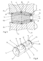
- la figure 1 est une vue en perspective de trois quart et de dessus d'un implant intersomatique selon un mode de réalisation de la présente invention ;
- la figure 2 est une vue de dessus de l'implant de la figure 1 ;
- la figure 3 est une vue de côté en coupe longitudinale montrant un implant de la figure 1 en position entre deux vertèbres ;
- la figure 4 est une coupe transversale selon le plan A-A de la figure 3 ;
- la figure 5 est une vue de côté en coupe longitudinale montrant un implant à forme générale en ovoïde à extrémités longitudinales tronquées ;
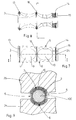
- la figure 6 est une vue en perspective de trois quart et de dessus d'un implant selon un second mode de réalisation de l'invention
- la figure 7 est une vue de dessus de l'implant de la figure 6 ;
- la figure 8 est une coupe longitudinale de l'implant de la figure 6 ; et
- la figure 9 est une coupe transversale de l'implant de la figure 6.
- Comme le représentent les figures, l'implant intersomatique selon l'invention est un élément tubulaire creux présentant un axe longitudinal I-I, réalisé par exemple en métal ou en matériau synthétique rigide, comprenant une cavité interne 1 délimitée par une paroi périphérique 2 ouverte au moins à une première extrémité 3.
- La paroi périphérique 2 comprend une surface externe 4 à section généralement circulaire. Cette surface externe 4 se compose de deux faces latérales 5 et 6 pleines et de deux faces respectives supérieure 7 et inférieure 8 munies de lumières de communication. Par exemple, la face supérieure 7 est munie de deux lumières de communication 9 et 10, la face inférieure 8 étant munie de deux lumières de communication 11 et 12.
- La paroi périphérique 2 comprend en outre au moins une nervure externe annulaire anti recul telle que la nervure 13 voisine de la première extrémité 3.
- Dans les modes de réalisation représentés, l'implant comprend une première nervure externe annulaire 13 au voisinage de sa première extrémité 3, une seconde nervure externe annulaire 14 au voisinage de sa seconde extrémité 15, et une nervure externe annulaire intermédiaire 16 ménagée sur une zone intermédiaire 17 de paroi périphérique 2 dépourvue de lumière de communication.
- De préférence, comme illustré dans le mode de réalisation représenté sur les figures 6 à 9, les nervures externes annulaires 13, 14 et 16 sont dentées, pour s'opposer à la fois à la translation axiale et à la rotation de l'implant, les dents venant s'incruster dans les plateaux vertébraux.
- En alternative, on peut prévoir une ou plusieurs nervures longitudinales faisant saillie sur la surface externe de la paroi périphérique 2. Ces moyens anti-rotation sont toutefois plus difficiles à réaliser que les dents de nervures externes annulaires.
- Dans tous les modes de réalisation, les lumières de communication 9, 10, 11 et 12 ont avantageusement une forme oblongue, de longueur seulement peu inférieure à la demi-longueur de l'implant, de largeur sensiblement égale au diamètre de l'implant.
- On comprendra qu'un implant selon l'invention peut comprendre une, deux ou trois nervures, ou un nombre plus important de nervures externes annulaires.
- De préférence, comme le représentent notamment les figures 3, 5 et 8, chaque nervure externe annulaire 13, 14 ou 16 présente une section transversale en dent de scie asymétrique s'opposant au déplacement de l'implant en direction de la seconde extrémité 15.
- Dans les modes de réalisation des figures 1 à 3 et 6 à 8, la paroi périphérique 2 présente une forme générale externe en tronc de cône dont la grande base est constituée par la face de première extrémité 3 et dont la petite base est constituée par la face de seconde extrémité 15. Une telle forme permet de redonner et de maintenir l'angle physiologique approprié entre deux vertèbres adjacentes.
- Dans le mode de réalisation de la figure 5, la paroi périphérique 2 présente une forme générale externe en ovoïde à extrémités longitudinales tronquées formant une grande base à la première extrémité 3 et une petite base à la seconde extrémité 15.
- La forme ovoïde est choisie de façon à épouser plus étroitement la forme anatomique des plateaux vertébraux entre lesquels l'implant vient s'insérer. Avant insertion de l'implant, on donne alors aux rainures un profil longitudinal adapté.
- Dans les modes de réalisation représentés, les faces latérales 5 et 6 sont dépourvues de nervures externes périphériques. En conséquence, comme on le voit mieux sur les figures 4 et 9, les nervures externes annulaires sont interrompues au droit de chaque face latérales 5 ou 6. Par exemple, la nervure périphérique 16 comporte deux interruptions supérieures respectives 18 et 19, et deux interruptions inférieures respectives 20 et 21, qui s'opposent à la rotation de l'implant lorsque celui-ci est engagé entre deux vertèbres adjacentes.
- Les surfaces externes des faces latérales 5 et 6 peuvent comprendre un méplat, comme représenté sur les figures 1, 4, 6 et 9, ce qui permet de réduire quelque peu la quantité de matière constituant l'implant. Le méplat occupe toute la longueur de la face latérale correspondante.
- La paroi périphérique 2 se raccorde, à sa seconde extrémité 15, à une paroi transversale d'appui 22. Cette paroi transversale d'appui 22 comprend un trou axial 23 taraudé, permettant l'adaptation d'un outil de pose en prolongement de l'implant.
- La paroi transversale d'appui 22 comprend en outre des reliefs externes, par exemple une rainure ou fente diamétrale 24, permettant de solidariser en rotation un instrument de pose sur l'implant.
- De préférence, les reliefs externes sont conformés de façon à constituer en eux-mêmes un moyen de repérage visuel de position angulaire de l'implant autour de son axe longitudinal I-I. Une structure de relief externe en forme de rainure ou fente diamétrale convient pour constituer un tel moyen de repérage visuel de position angulaire. Cela permet en particulier de positionner l'implant entre deux vertèbres de façon que les faces supérieure 7 et inférieure 8 soit en regard des faces correspondantes des deux vertèbres adjacentes entre lesquelles l'implant est engagé.
- Les figures 3, 4, 5 et 9 représentent un implant selon l'invention en position entre deux vertèbres adjacentes 25 et 26.
- Préalablement à la pose de l'insert, on introduit dans sa cavité interne 1 un greffon d'os spongieux 100 prélevé dans une autre partie du corps du patient.
- Avant d'engager l'implant entre les deux vertèbres, on réalise dans les plateaux respectifs de chaque vertèbre une rainure de section appropriée orientée sagittalement par rapport à l'axe longitudinal du rachis, l'ensemble des deux rainures formant sensiblement un logement cylindrique dont la section correspond sensiblement à la dimension de la seconde extrémité 15 de l'implant. On écarte ensuite les deux vertèbres 25 et 26 par des moyens appropriés, et l'on insère axialement l'implant dans les deux rainures, puis l'on relâche les vertèbres. La forme en tronc de cône de l'implant donne aux vertèbres 25 et 26 une angulation appropriée, reproduisant l'angle morphologique normal tel que la lordose lombaire anatomique. Les nervures externes annulaires 13, 14 et 16 s'engagent dans l'os formant les vertèbres 25 et 26, et interdisent le déplacement axial de l'insert. Les extrémités 18 à 21 des nervures externes annulaires, ainsi que les dents ou nervures longitudinales, en appui sur l'os empêchent également la rotation de l'insert autour de son axe longitudinal.
- Après la pose, le greffon d'os spongieux 100 est en contact avec l'os des vertèbres inférieure 25 et supérieure 26, de façon à assurer progressivement la fusion des vertèbres l'une à l'autre. La taille importante des lumières de communication 9, 10, 11 et 12 favorise cette fusion, en assurant un bon contact entre le greffon interne 100 et l'os des deux vertèbres 25 et 26.
- Les faces latérales pleines 5 et 6 de l'insert selon l'invention assurent une bonne rigidité de l'insert, pour reprendre les efforts de compression entre les deux vertèbres 25 et 26.
- La section généralement circulaire de l'insert évite le risque de lésion neurologique lors de l'insertion de l'insert entre les deux vertèbres.
- La présente invention n'est pas limitée aux modes de réalisation qui ont été explicitement décrits, mais elle en inclut les diverses variantes et généralisations contenues dans le domaine des revendications ci-après.
Claims (12)
Applications Claiming Priority (2)
| Application Number | Priority Date | Filing Date | Title |
|---|---|---|---|
| FR9309835 | 1993-08-06 | ||
| FR9309835A FR2708461B1 (fr) | 1993-08-06 | 1993-08-06 | Implant intersomatique pour colonne vertébrale. |
Publications (2)
| Publication Number | Publication Date |
|---|---|
| EP0637440A1 true EP0637440A1 (fr) | 1995-02-08 |
| EP0637440B1 EP0637440B1 (fr) | 1997-10-15 |
Family
ID=9450095
Family Applications (1)
| Application Number | Title | Priority Date | Filing Date |
|---|---|---|---|
| EP94420224A Expired - Lifetime EP0637440B1 (fr) | 1993-08-06 | 1994-08-01 | Implant intersomatique pour colonne vertébrale |
Country Status (12)
| Country | Link |
|---|---|
| US (1) | US5683463A (fr) |
| EP (1) | EP0637440B1 (fr) |
| JP (1) | JP2558438B2 (fr) |
| KR (1) | KR950005279A (fr) |
| AT (1) | ATE159167T1 (fr) |
| AU (1) | AU668654B2 (fr) |
| CA (1) | CA2128932C (fr) |
| DE (1) | DE69406216T2 (fr) |
| FI (1) | FI943640A (fr) |
| FR (1) | FR2708461B1 (fr) |
| NZ (1) | NZ264176A (fr) |
| TW (1) | TW267932B (fr) |
Cited By (39)
| Publication number | Priority date | Publication date | Assignee | Title |
|---|---|---|---|---|
| DE29600879U1 (de) * | 1996-01-19 | 1996-03-28 | Howmedica Gmbh | Wirbelsäulenimplantat |
| EP0732093A2 (fr) * | 1995-02-17 | 1996-09-18 | Sofamor Danek Group, Inc. | Implants spinaux intersomatiques pour fusion |
| EP0734703A2 (fr) * | 1995-03-27 | 1996-10-02 | Danek Medical, Inc. | Dispositif de fusion intervertébrale et procédé de rétablissement d'une anatomie spinale normale |
| FR2742044A1 (fr) * | 1995-12-11 | 1997-06-13 | Medinov Sa | Prothese d'arthrodese intersomatique vertebrale |
| FR2742652A1 (fr) * | 1995-12-21 | 1997-06-27 | Colorado | Implant intervertebral du type cage intersomatique |
| EP0781113A1 (fr) * | 1994-09-15 | 1997-07-02 | Surgical Dynamics, Inc. | Cage de fusion anterieure de forme conique et procede d'implantation |
| WO1997037619A1 (fr) * | 1996-04-10 | 1997-10-16 | Synthes Ag Chur | Implant intervertebral |
| WO1998010722A1 (fr) * | 1996-09-13 | 1998-03-19 | Cage Concepts Llc | Cage d'osteosynthese expansive |
| EP0831759A1 (fr) * | 1995-06-07 | 1998-04-01 | MICHELSON, Gary Karlin | Arthrodheses intersomatiques du rachis a filetage tronconique |
| EP0832622A2 (fr) | 1996-09-26 | 1998-04-01 | Howmedica GmbH | Ensemble de cage vertébrale |
| EP0834295A1 (fr) * | 1996-10-03 | 1998-04-08 | Medinov-Amp | Prothèse d'arthrodèse intersomatique vertébrale |
| EP0840580A1 (fr) * | 1995-06-07 | 1998-05-13 | MICHELSON, Gary Karlin | Arthrodheses intersomatiques du rachis lordosiques |
| FR2767675A1 (fr) * | 1997-08-26 | 1999-03-05 | Materiel Orthopedique En Abreg | Implant intersomatique et ancillaire de preparation adapte pour permettre sa pose |
| WO2000045752A1 (fr) * | 1999-02-04 | 2000-08-10 | Aesculap Ag & Co. Kg | Vis de liaison rehabitable pour l'arthrodese d'une articulation osseuse, notamment pour la stabilisation de deux vertebres |
| WO2000045753A1 (fr) * | 1999-02-04 | 2000-08-10 | Sdgi Holdings, Inc. | Dispositif ameliore de fusion entre les corps vertebraux presentant des caracteristiques anti-rotation |
| FR2794967A1 (fr) * | 1999-06-21 | 2000-12-22 | Medicrea | Ogive dilatatrice introduite entre des surfaces osseuses articulaires concaves pour en restaurer l'ecartement et la position angulaire |
| WO2001028461A2 (fr) * | 1999-10-20 | 2001-04-26 | Sdgi Holdings, Inc. | Implant de support orthopedique pour os enfonce |
| US6241770B1 (en) | 1999-03-05 | 2001-06-05 | Gary K. Michelson | Interbody spinal fusion implant having an anatomically conformed trailing end |
| EP1175878A2 (fr) * | 1994-12-12 | 2002-01-30 | Surgical Dynamics, Inc. | Cage de fusion de forme conique |
| US6350283B1 (en) | 2000-04-19 | 2002-02-26 | Gary K. Michelson | Bone hemi-lumbar interbody spinal implant having an asymmetrical leading end and method of installation thereof |
| AU752060B2 (en) * | 1995-02-17 | 2002-09-05 | Warsaw Orthopedic, Inc. | Improved interbody spinal fusion implants |
| EP1302182A2 (fr) * | 1995-06-07 | 2003-04-16 | MICHELSON, Gary Karlin | Arthrodese translateral du rachis |
| US6558423B1 (en) | 1999-05-05 | 2003-05-06 | Gary K. Michelson | Interbody spinal fusion implants with multi-lock for locking opposed screws |
| EP1447061A1 (fr) | 1993-09-21 | 2004-08-18 | SYNTHES AG Chur | Implant pour l'espace intervertébral |
| US6866682B1 (en) | 1999-09-02 | 2005-03-15 | Stryker Spine | Distractable corpectomy device |
| US6890355B2 (en) | 2001-04-02 | 2005-05-10 | Gary K. Michelson | Artificial contoured spinal fusion implants made of a material other than bone |
| US6955691B2 (en) | 2003-11-21 | 2005-10-18 | Kyungwon Medical Co., Ltd. | Expandable interfusion cage |
| US6989031B2 (en) | 2001-04-02 | 2006-01-24 | Sdgi Holdings, Inc. | Hemi-interbody spinal implant manufactured from a major long bone ring or a bone composite |
| US7051417B2 (en) | 1999-12-08 | 2006-05-30 | Sdgi Holdings, Inc. | Method for forming an orthopedic implant surface configuration |
| US7156875B2 (en) | 2000-04-19 | 2007-01-02 | Warsaw Orthopedic, Inc. | Arcuate artificial hemi-lumbar interbody spinal fusion implant having an asymmetrical leading end |
| US7166129B2 (en) | 1999-12-08 | 2007-01-23 | Warsaw Orthopedic, Inc. | Method for forming a spinal implant surface configuration |
| US7169183B2 (en) | 2000-03-14 | 2007-01-30 | Warsaw Orthopedic, Inc. | Vertebral implant for promoting arthrodesis of the spine |
| CN100425214C (zh) * | 1995-03-27 | 2008-10-15 | Sdgi集团有限公司 | 用于植入体内融合装置的驱动工具 |
| US7942933B2 (en) | 1995-06-07 | 2011-05-17 | Warsaw Orthopedic, Inc. | Frusto-conical spinal implant |
| US8337559B2 (en) | 2005-04-21 | 2012-12-25 | Globus Medical, Inc. | Expandable vertebral prosthesis |
| US8460380B2 (en) | 2004-02-13 | 2013-06-11 | Franz Copf, JR. | Intervertebral implant and surgical method for spondylodesis of a lumbar vertebral column |
| US9597198B2 (en) | 2006-02-15 | 2017-03-21 | Ldr Medical | Transforaminal intersomatic cage for an intervertebral fusion graft and an instrument for implanting the cage |
| US9707095B2 (en) | 2014-06-04 | 2017-07-18 | Wenzel Spine, Inc. | Bilaterally expanding intervertebral body fusion device |
| US11219531B2 (en) | 2019-04-10 | 2022-01-11 | Wenzel Spine, Inc. | Rotatable intervertebral spacing implant |
Families Citing this family (121)
| Publication number | Priority date | Publication date | Assignee | Title |
|---|---|---|---|---|
| US6123705A (en) | 1988-06-13 | 2000-09-26 | Sdgi Holdings, Inc. | Interbody spinal fusion implants |
| US6210412B1 (en) | 1988-06-13 | 2001-04-03 | Gary Karlin Michelson | Method for inserting frusto-conical interbody spinal fusion implants |
| US7491205B1 (en) | 1988-06-13 | 2009-02-17 | Warsaw Orthopedic, Inc. | Instrumentation for the surgical correction of human thoracic and lumbar spinal disease from the lateral aspect of the spine |
| US6758849B1 (en) | 1995-02-17 | 2004-07-06 | Sdgi Holdings, Inc. | Interbody spinal fusion implants |
| DE59509539D1 (de) * | 1995-03-08 | 2001-09-27 | Synthes Ag | Zwischenwirbel-implantat |
| US6206922B1 (en) | 1995-03-27 | 2001-03-27 | Sdgi Holdings, Inc. | Methods and instruments for interbody fusion |
| DE69732226T2 (de) * | 1995-03-27 | 2005-12-22 | SDGI Holdings, Inc., Wilmington | Wirbelsäulenfusionsimplantat und einführ- und überprüfungswerkzeuge |
| US20020143402A1 (en) * | 1995-09-04 | 2002-10-03 | Limber Ltd. | Hip joint prostheses |
| ES2158132T3 (es) * | 1995-10-20 | 2001-09-01 | Synthes Ag | Implante intervertebral con caja y cuerpo de rotacion. |
| KR100415064B1 (ko) * | 1995-10-20 | 2005-04-06 | 신테스 아게 츄어 | 추골간임플랜트 |
| US5865845A (en) | 1996-03-05 | 1999-02-02 | Thalgott; John S. | Prosthetic intervertebral disc |
| FR2747034B1 (fr) * | 1996-04-03 | 1998-06-19 | Scient X | Systeme de contention et de fusion intersomatique |
| KR100553297B1 (ko) * | 1997-04-25 | 2006-02-20 | 스뜨리케르 프랑스 | 두 부품으로 구성된 체강내의 임플란트 |
| US5876457A (en) * | 1997-05-20 | 1999-03-02 | George J. Picha | Spinal implant |
| USRE38614E1 (en) | 1998-01-30 | 2004-10-05 | Synthes (U.S.A.) | Intervertebral allograft spacer |
| US6086593A (en) | 1998-06-30 | 2000-07-11 | Bonutti; Peter M. | Method and apparatus for use in operating on a bone |
| WO2000007527A1 (fr) | 1998-08-03 | 2000-02-17 | Synthes Ag Chur | Espaceur d'allogreffe intervertebral |
| US6099531A (en) * | 1998-08-20 | 2000-08-08 | Bonutti; Peter M. | Changing relationship between bones |
| FR2782632B1 (fr) * | 1998-08-28 | 2000-12-29 | Materiel Orthopedique En Abreg | Cage de fusion intersomatique expansible |
| US6117174A (en) * | 1998-09-16 | 2000-09-12 | Nolan; Wesley A. | Spinal implant device |
| US6159244A (en) * | 1999-07-30 | 2000-12-12 | Suddaby; Loubert | Expandable variable angle intervertebral fusion implant |
| US6547823B2 (en) | 1999-01-22 | 2003-04-15 | Osteotech, Inc. | Intervertebral implant |
| AU762689B2 (en) * | 1999-04-07 | 2003-07-03 | Howmedica Osteonics Corp. | Low profile fusion cage and insertion set |
| EP1198208B1 (fr) * | 1999-05-05 | 2013-07-10 | Warsaw Orthopedic, Inc. | Implants emboîtables de fusion de vertèbres logés entre les corps vertébraux |
| US6277149B1 (en) | 1999-06-08 | 2001-08-21 | Osteotech, Inc. | Ramp-shaped intervertebral implant |
| AU7080200A (en) | 1999-08-26 | 2001-03-19 | Sdgi Holdings, Inc. | Devices and methods for implanting fusion cages |
| FR2798059B1 (fr) | 1999-09-08 | 2002-03-22 | Phusis | Implant intersomatique, dispositif pour la stabilisation du rachis et kit pour la realisation d'une arthrodese |
| CA2386328C (fr) | 1999-10-19 | 2008-08-19 | Sdgi Holdings, Inc. | Implant vertebral et instrument preparatoire sous forme d'outil coupant servant a mettre l'implant en place |
| FR2801783B1 (fr) * | 1999-12-02 | 2002-06-14 | Claude Laville | Cage intersomatique |
| AU2624801A (en) | 1999-12-30 | 2001-07-16 | Osteotech, Inc. | Intervertebral implants |
| US6332895B1 (en) | 2000-03-08 | 2001-12-25 | Loubert Suddaby | Expandable intervertebral fusion implant having improved stability |
| AR027685A1 (es) * | 2000-03-22 | 2003-04-09 | Synthes Ag | Forma de tejido y metodo para realizarlo |
| US6436141B2 (en) | 2000-04-07 | 2002-08-20 | Surgical Dynamics, Inc. | Apparatus for fusing adjacent bone structures |
| JP2004516040A (ja) | 2000-06-30 | 2004-06-03 | リトラン、スティーブン | 多軸継手装置及び方法 |
| US20020038123A1 (en) * | 2000-09-20 | 2002-03-28 | Visotsky Jeffrey L. | Osteotomy implant |
| US6692434B2 (en) | 2000-09-29 | 2004-02-17 | Stephen Ritland | Method and device for retractor for microsurgical intermuscular lumbar arthrodesis |
| US7166073B2 (en) | 2000-09-29 | 2007-01-23 | Stephen Ritland | Method and device for microsurgical intermuscular spinal surgery |
| US20030120274A1 (en) | 2000-10-20 | 2003-06-26 | Morris John W. | Implant retaining device |
| WO2002034170A2 (fr) * | 2000-10-24 | 2002-05-02 | Howmedica Osteonics Corp. | Appareil en forme de fut pour assurer la fusion avec des structures osseuses adjacentes |
| US20020169507A1 (en) | 2000-12-14 | 2002-11-14 | David Malone | Interbody spine fusion cage |
| US20020120335A1 (en) * | 2001-02-28 | 2002-08-29 | Angelucci Christopher M. | Laminoplasty implants and methods of use |
| US20020138147A1 (en) * | 2001-03-22 | 2002-09-26 | Surgical Dynamics, Inc. | Apparatus for fusing adjacent bone structures |
| US6749636B2 (en) | 2001-04-02 | 2004-06-15 | Gary K. Michelson | Contoured spinal fusion implants made of bone or a bone composite material |
| US6719794B2 (en) | 2001-05-03 | 2004-04-13 | Synthes (U.S.A.) | Intervertebral implant for transforaminal posterior lumbar interbody fusion procedure |
| US6974480B2 (en) * | 2001-05-03 | 2005-12-13 | Synthes (Usa) | Intervertebral implant for transforaminal posterior lumbar interbody fusion procedure |
| US6635087B2 (en) | 2001-08-29 | 2003-10-21 | Christopher M. Angelucci | Laminoplasty implants and methods of use |
| WO2003026523A1 (fr) | 2001-09-28 | 2003-04-03 | Stephen Ritland | Tige de connexion pour systeme polyaxial a vis ou crochet et procede d'utilisation |
| US6979353B2 (en) | 2001-12-03 | 2005-12-27 | Howmedica Osteonics Corp. | Apparatus for fusing adjacent bone structures |
| US6855167B2 (en) | 2001-12-05 | 2005-02-15 | Osteotech, Inc. | Spinal intervertebral implant, interconnections for such implant and processes for making |
| AR038680A1 (es) | 2002-02-19 | 2005-01-26 | Synthes Ag | Implante intervertebral |
| US7763047B2 (en) | 2002-02-20 | 2010-07-27 | Stephen Ritland | Pedicle screw connector apparatus and method |
| DE20205016U1 (de) * | 2002-03-30 | 2003-08-14 | Mathys Medizinaltechnik Ag Bet | Chirurgisches Implantat |
| US6783547B2 (en) * | 2002-04-05 | 2004-08-31 | Howmedica Corp. | Apparatus for fusing adjacent bone structures |
| US6966910B2 (en) | 2002-04-05 | 2005-11-22 | Stephen Ritland | Dynamic fixation device and method of use |
| AU2003228960B2 (en) | 2002-05-08 | 2009-06-11 | Stephen Ritland | Dynamic fixation device and method of use |
| US7044971B2 (en) * | 2002-08-30 | 2006-05-16 | Loubert Suddaby | Lordotic fusion implant |
| US7063725B2 (en) | 2002-10-21 | 2006-06-20 | Sdgi Holdings, Inc. | Systems and techniques for restoring and maintaining intervertebral anatomy |
| US7125425B2 (en) | 2002-10-21 | 2006-10-24 | Sdgi Holdings, Inc. | Systems and techniques for restoring and maintaining intervertebral anatomy |
| US8147548B2 (en) | 2005-03-21 | 2012-04-03 | Kyphon Sarl | Interspinous process implant having a thread-shaped wing and method of implantation |
| US20080021468A1 (en) | 2002-10-29 | 2008-01-24 | Zucherman James F | Interspinous process implants and methods of use |
| FR2848414B1 (fr) * | 2002-12-17 | 2005-02-25 | Vitatech | Implant intersomatique pour vertebres |
| US7192447B2 (en) | 2002-12-19 | 2007-03-20 | Synthes (Usa) | Intervertebral implant |
| EP2335656B1 (fr) | 2003-02-06 | 2012-09-05 | Synthes GmbH | Implant intervertébral |
| US7094257B2 (en) * | 2003-02-14 | 2006-08-22 | Zimmer Spine, Inc. | Expandable intervertebral implant cage |
| CA2516791C (fr) | 2003-02-25 | 2011-12-13 | Stephen Ritland | Dispositif a tige ajustable et connecteur, et son procede d'utilisation |
| US7819903B2 (en) | 2003-03-31 | 2010-10-26 | Depuy Spine, Inc. | Spinal fixation plate |
| WO2004110247A2 (fr) | 2003-05-22 | 2004-12-23 | Stephen Ritland | Guide intermusculaire pour l'insertion d'un ecarteur et procede d'utilisation |
| US7226482B2 (en) | 2003-09-02 | 2007-06-05 | Synthes (U.S.A.) | Multipiece allograft implant |
| US7837732B2 (en) | 2003-11-20 | 2010-11-23 | Warsaw Orthopedic, Inc. | Intervertebral body fusion cage with keels and implantation methods |
| US7691146B2 (en) | 2003-11-21 | 2010-04-06 | Kyphon Sarl | Method of laterally inserting an artificial vertebral disk replacement implant with curved spacer |
| EP1708651A4 (fr) | 2004-01-27 | 2011-11-02 | Osteotech Inc | Greffe osseuse stabilisee |
| CN2707201Y (zh) * | 2004-06-21 | 2005-07-06 | 李孔嘉 | 脊椎重建复位器 |
| US7455639B2 (en) | 2004-09-20 | 2008-11-25 | Stephen Ritland | Opposing parallel bladed retractor and method of use |
| JP4831435B2 (ja) * | 2004-10-08 | 2011-12-07 | ウォーソー・オーソペディック・インコーポレーテッド | 内部接続椎体間ケージ挿入用の器具、及び装置 |
| US7655046B2 (en) * | 2005-01-20 | 2010-02-02 | Warsaw Orthopedic, Inc. | Expandable spinal fusion cage and associated instrumentation |
| WO2006091807A2 (fr) * | 2005-02-23 | 2006-08-31 | Small Bone Innovations, Inc | Implants osseux |
| US20060217717A1 (en) * | 2005-03-24 | 2006-09-28 | Dale Whipple | Methods and devices for stabilizing a bone anchor |
| US7648456B2 (en) * | 2005-04-01 | 2010-01-19 | Coloplast A/S | Adapter for penile prosthesis tip extender |
| CA2615497C (fr) | 2005-07-19 | 2014-03-25 | Stephen Ritland | Tige d'extension permettant d'etendre un produit de fusion |
| EP1988855A2 (fr) | 2006-02-27 | 2008-11-12 | Synthes GmbH | Implant intervertebral avec geometrie de fixation |
| US7959564B2 (en) | 2006-07-08 | 2011-06-14 | Stephen Ritland | Pedicle seeker and retractor, and methods of use |
| US8043377B2 (en) | 2006-09-02 | 2011-10-25 | Osprey Biomedical, Inc. | Implantable intervertebral fusion device |
| US8097037B2 (en) * | 2006-12-20 | 2012-01-17 | Depuy Spine, Inc. | Methods and devices for correcting spinal deformities |
| US7824427B2 (en) * | 2007-01-16 | 2010-11-02 | Perez-Cruet Miquelangelo J | Minimally invasive interbody device |
| CA2677903A1 (fr) | 2007-02-12 | 2008-08-21 | Osteotech, Inc. | Implant pour reintervention en chirurgie articulaire |
| US8556976B2 (en) | 2007-03-01 | 2013-10-15 | The Center For Orthopedic Research And Education, Inc. | Spinal interbody spacer device |
| US8491656B2 (en) * | 2007-04-05 | 2013-07-23 | George R. Schoedinger, III | Arthrodesis of vertebral bodies |
| DE102007039899B3 (de) * | 2007-08-23 | 2009-04-09 | Siemens Ag | Sensor zum Ermöglichen des Nachweises einer Substanz im Körper eines Lebewesens |
| BRPI0820172A2 (pt) | 2007-11-16 | 2015-06-16 | Synthes Gmbh | Implante intervertebral de perfil baixo |
| CA2742812A1 (fr) | 2008-11-07 | 2010-05-14 | William P. Mcdonough | Espaceur intercalaire a profil nul et mecanisme de plaque couplee |
| BRPI1008924A2 (pt) | 2009-03-16 | 2017-06-06 | Synthes Gmbh | sistema e método para estabilizar vértebra em cirurgia de espinha através de um canal de acesso lateral |
| US20100286785A1 (en) * | 2009-05-01 | 2010-11-11 | Danny Wayne Grayson | Method and apparatus for spinal interbody fusion |
| US9668882B2 (en) * | 2009-10-02 | 2017-06-06 | Amedica Corporation | Biomedical implant inserters and related apparatus, systems, and methods |
| US9028553B2 (en) | 2009-11-05 | 2015-05-12 | DePuy Synthes Products, Inc. | Self-pivoting spinal implant and associated instrumentation |
| WO2012012327A1 (fr) | 2010-07-20 | 2012-01-26 | X-Spine Systems, Inc. | Implant orthopédique composite présentant un substrat à frottement réduit avec des caractéristiques de frottement primaires et des caractéristiques de frottement secondaires |
| EP2654626B1 (fr) | 2010-12-21 | 2016-02-24 | Synthes GmbH | Implants intervertébraux et systèmes |
| US9241809B2 (en) | 2010-12-21 | 2016-01-26 | DePuy Synthes Products, Inc. | Intervertebral implants, systems, and methods of use |
| WO2013025702A1 (fr) | 2011-08-16 | 2013-02-21 | Osteospring Medical, Inc. | Dispositifs de fixation de fracture en forme de coude et procédés d'utilisation associés |
| US9381048B2 (en) | 2011-08-31 | 2016-07-05 | DePuy Synthes Products, Inc. | Devices and methods for cervical lateral fixation |
| US10022245B2 (en) | 2012-12-17 | 2018-07-17 | DePuy Synthes Products, Inc. | Polyaxial articulating instrument |
| US11311312B2 (en) | 2013-03-15 | 2022-04-26 | Medtronic, Inc. | Subcutaneous delivery tool |
| US9198774B2 (en) * | 2013-11-21 | 2015-12-01 | Perumala Corporation | Intervertebral disk cage and stabilizer |
| US9867718B2 (en) | 2014-10-22 | 2018-01-16 | DePuy Synthes Products, Inc. | Intervertebral implants, systems, and methods of use |
| WO2016137983A1 (fr) | 2015-02-24 | 2016-09-01 | X-Spine Systems, Inc. | Système de fixation interépineux modulaire à élément fileté |
| CN105496609B (zh) * | 2015-12-17 | 2017-12-01 | 北京市春立正达医疗器械股份有限公司 | 一种翻修钛网 |
| US10314718B2 (en) | 2016-09-22 | 2019-06-11 | Loubert S. Suddaby | Expandable intervertebral fusion implant |
| US11701239B2 (en) | 2017-01-26 | 2023-07-18 | Loubert S. Suddaby | Stand-alone expandable interbody spinal fusion device with integrated fixation mechanism |
| US11207192B2 (en) | 2017-01-26 | 2021-12-28 | Loubert S. Suddaby | Stand-alone expandable interbody spinal fusion device with integrated fixation mechanism |
| US10966843B2 (en) | 2017-07-18 | 2021-04-06 | DePuy Synthes Products, Inc. | Implant inserters and related methods |
| US11045331B2 (en) | 2017-08-14 | 2021-06-29 | DePuy Synthes Products, Inc. | Intervertebral implant inserters and related methods |
| US10470895B2 (en) | 2017-08-16 | 2019-11-12 | Loubert S. Suddaby | Endoscopically implantable fusion implant for endoscopic spinal surgery |
| US11219532B2 (en) | 2017-09-18 | 2022-01-11 | Loubert S. Suddaby | Stand-alone expandable interbody spinal fusion device with locking mechanism |
| US10596010B2 (en) | 2017-09-18 | 2020-03-24 | Loubert S. Suddaby | Stand-alone expandable interbody spinal fusion device with locking mechanism |
| US10792165B2 (en) | 2017-10-18 | 2020-10-06 | Loubert S. Suddaby | Expandable intervertebral implant for treatment of scoliosis |
| US11331196B2 (en) | 2017-10-18 | 2022-05-17 | Loubert S. Suddaby | Expandable intervertebral implant for treatment of scoliosis |
| AU2019300119B2 (en) * | 2018-07-10 | 2022-06-09 | Adler Ortho S.P.A. | Device for facilitating the formation of new bone tissue |
| USD955579S1 (en) | 2019-04-26 | 2022-06-21 | Warsaw Orthopedic, Inc. | Surgical implant |
| USD948048S1 (en) | 2019-04-26 | 2022-04-05 | Warsaw Orthopedic, Inc. | Surgical implant |
| US10905567B2 (en) | 2019-04-26 | 2021-02-02 | Warsaw Orthopedic, Inc. | Spinal implant system and method |
| US10898346B1 (en) | 2019-07-19 | 2021-01-26 | Loubert S. Suddaby | Expandable intervertebral fusion implant |
| US11026805B2 (en) | 2019-07-30 | 2021-06-08 | Loubert S. Suddaby | Expandable intervertebral fusion implant |
Citations (6)
| Publication number | Priority date | Publication date | Assignee | Title |
|---|---|---|---|---|
| US4349921A (en) * | 1980-06-13 | 1982-09-21 | Kuntz J David | Intervertebral disc prosthesis |
| US4501269A (en) * | 1981-12-11 | 1985-02-26 | Washington State University Research Foundation, Inc. | Process for fusing bone joints |
| WO1987007827A1 (fr) * | 1986-06-19 | 1987-12-30 | S + G Implants Gmbh | Implant pour la fixation de deux vertebres contigues |
| EP0307241A2 (fr) * | 1987-09-11 | 1989-03-15 | John W. Brantigan | Implant de prothèse chirurgical |
| WO1989012431A1 (fr) * | 1988-06-13 | 1989-12-28 | Michelson Gary K | Implant spinal filete |
| US4936848A (en) * | 1989-09-22 | 1990-06-26 | Bagby George W | Implant for vertebrae |
Family Cites Families (4)
| Publication number | Priority date | Publication date | Assignee | Title |
|---|---|---|---|---|
| US4645453A (en) * | 1985-09-19 | 1987-02-24 | Niznick Gerald A | Bendable adapter for dental implant |
| US4961740B1 (en) * | 1988-10-17 | 1997-01-14 | Surgical Dynamics Inc | V-thread fusion cage and method of fusing a bone joint |
| US5458638A (en) * | 1989-07-06 | 1995-10-17 | Spine-Tech, Inc. | Non-threaded spinal implant |
| CA2093900C (fr) * | 1993-04-13 | 1996-12-10 | Norman H. K. Kwan | Implant dentaire muni de surfaces coupantes |
-
1993
- 1993-08-06 FR FR9309835A patent/FR2708461B1/fr not_active Expired - Fee Related
-
1994
- 1994-07-25 TW TW083106785A patent/TW267932B/zh active
- 1994-07-27 US US08/281,243 patent/US5683463A/en not_active Expired - Fee Related
- 1994-07-27 CA CA002128932A patent/CA2128932C/fr not_active Expired - Fee Related
- 1994-07-29 JP JP6179134A patent/JP2558438B2/ja not_active Expired - Lifetime
- 1994-08-01 DE DE69406216T patent/DE69406216T2/de not_active Expired - Fee Related
- 1994-08-01 AT AT94420224T patent/ATE159167T1/de not_active IP Right Cessation
- 1994-08-01 EP EP94420224A patent/EP0637440B1/fr not_active Expired - Lifetime
- 1994-08-03 AU AU68900/94A patent/AU668654B2/en not_active Ceased
- 1994-08-04 KR KR1019940019240A patent/KR950005279A/ko not_active Application Discontinuation
- 1994-08-04 NZ NZ264176A patent/NZ264176A/en unknown
- 1994-08-05 FI FI943640A patent/FI943640A/fi unknown
Patent Citations (6)
| Publication number | Priority date | Publication date | Assignee | Title |
|---|---|---|---|---|
| US4349921A (en) * | 1980-06-13 | 1982-09-21 | Kuntz J David | Intervertebral disc prosthesis |
| US4501269A (en) * | 1981-12-11 | 1985-02-26 | Washington State University Research Foundation, Inc. | Process for fusing bone joints |
| WO1987007827A1 (fr) * | 1986-06-19 | 1987-12-30 | S + G Implants Gmbh | Implant pour la fixation de deux vertebres contigues |
| EP0307241A2 (fr) * | 1987-09-11 | 1989-03-15 | John W. Brantigan | Implant de prothèse chirurgical |
| WO1989012431A1 (fr) * | 1988-06-13 | 1989-12-28 | Michelson Gary K | Implant spinal filete |
| US4936848A (en) * | 1989-09-22 | 1990-06-26 | Bagby George W | Implant for vertebrae |
Cited By (87)
| Publication number | Priority date | Publication date | Assignee | Title |
|---|---|---|---|---|
| EP1447061A1 (fr) | 1993-09-21 | 2004-08-18 | SYNTHES AG Chur | Implant pour l'espace intervertébral |
| EP1464306B2 (fr) † | 1993-09-21 | 2014-06-11 | Synthes GmbH | Implant pour l'espace intervertébral |
| EP0781113A1 (fr) * | 1994-09-15 | 1997-07-02 | Surgical Dynamics, Inc. | Cage de fusion anterieure de forme conique et procede d'implantation |
| EP0781113A4 (fr) * | 1994-09-15 | 1997-12-29 | Surgical Dynamics Inc | Cage de fusion anterieure de forme conique et procede d'implantation |
| US5906616A (en) * | 1994-09-15 | 1999-05-25 | Surgical Dynamics, Inc. | Conically shaped anterior fusion cage and method of implantation |
| EP1175878A2 (fr) * | 1994-12-12 | 2002-01-30 | Surgical Dynamics, Inc. | Cage de fusion de forme conique |
| EP1175878A3 (fr) * | 1994-12-12 | 2002-02-06 | Surgical Dynamics, Inc. | Cage de fusion de forme conique |
| EP1525863A3 (fr) * | 1995-02-17 | 2007-01-31 | Warsaw Orthopedic, Inc. | Implantations spinaux de fusion courbés à rochet |
| EP0732093A3 (fr) * | 1995-02-17 | 1997-03-12 | Sofamor Danek Group Inc | Implants spinaux intersomatiques pour fusion |
| AU752060B2 (en) * | 1995-02-17 | 2002-09-05 | Warsaw Orthopedic, Inc. | Improved interbody spinal fusion implants |
| EP0732093A2 (fr) * | 1995-02-17 | 1996-09-18 | Sofamor Danek Group, Inc. | Implants spinaux intersomatiques pour fusion |
| AU716409B2 (en) * | 1995-02-17 | 2000-02-24 | Warsaw Orthopedic, Inc. | Improved interbody spinal fusion implants |
| CN100425214C (zh) * | 1995-03-27 | 2008-10-15 | Sdgi集团有限公司 | 用于植入体内融合装置的驱动工具 |
| EP0734703A3 (fr) * | 1995-03-27 | 1997-02-26 | Danek Medical Inc | Dispositif de fusion intervertébrale et procédé de rétablissement d'une anatomie spinale normale |
| EP1325719A3 (fr) * | 1995-03-27 | 2003-07-16 | SDGI Holdings, Inc. | Dispositif de fusion intervertébrale |
| US6375655B1 (en) | 1995-03-27 | 2002-04-23 | Sdgi Holdings, Inc. | Interbody fusion device and method for restoration of normal spinal anatomy |
| EP0734703A2 (fr) * | 1995-03-27 | 1996-10-02 | Danek Medical, Inc. | Dispositif de fusion intervertébrale et procédé de rétablissement d'une anatomie spinale normale |
| EP1147751A3 (fr) * | 1995-03-27 | 2001-10-31 | SDGI Holdings, Inc. | Dispositif de fusion intervertébrale et procédé de rétablissement d'une anatomie spinale normale |
| EP1147751A2 (fr) * | 1995-03-27 | 2001-10-24 | SDGI Holdings, Inc. | Dispositif de fusion intervertébrale et procédé de rétablissement d'une anatomie spinale normale |
| EP1302182A2 (fr) * | 1995-06-07 | 2003-04-16 | MICHELSON, Gary Karlin | Arthrodese translateral du rachis |
| EP1302182A3 (fr) * | 1995-06-07 | 2004-01-14 | MICHELSON, Gary Karlin | Arthrodèse translatéral du rachis |
| EP0831759A1 (fr) * | 1995-06-07 | 1998-04-01 | MICHELSON, Gary Karlin | Arthrodheses intersomatiques du rachis a filetage tronconique |
| EP0831759B1 (fr) * | 1995-06-07 | 2004-03-10 | MICHELSON, Gary Karlin | Arthrodheses intersomatiques du rachis a filetage tronconique |
| EP0840580A4 (fr) * | 1995-06-07 | 2000-08-09 | Michelson Gary K | Arthrodheses intersomatiques du rachis lordosiques |
| US7942933B2 (en) | 1995-06-07 | 2011-05-17 | Warsaw Orthopedic, Inc. | Frusto-conical spinal implant |
| EP0840580A1 (fr) * | 1995-06-07 | 1998-05-13 | MICHELSON, Gary Karlin | Arthrodheses intersomatiques du rachis lordosiques |
| CN100396248C (zh) * | 1995-06-07 | 2008-06-25 | Sdgi控股有限公司 | 平移式脊骨植入物 |
| EP1829503A2 (fr) | 1995-06-07 | 2007-09-05 | Warsaw Orthopedic, Inc. | Implant de soudure spinal doté d'une trappe d'accès |
| EP1829503A3 (fr) * | 1995-06-07 | 2007-09-19 | Warsaw Orthopedic, Inc. | Implant de soudure spinal doté d'une trappe d'accès |
| FR2742044A1 (fr) * | 1995-12-11 | 1997-06-13 | Medinov Sa | Prothese d'arthrodese intersomatique vertebrale |
| WO1997023174A1 (fr) * | 1995-12-21 | 1997-07-03 | Colorado | Implant intervertebral du type cage intersomatique |
| FR2742652A1 (fr) * | 1995-12-21 | 1997-06-27 | Colorado | Implant intervertebral du type cage intersomatique |
| US6019760A (en) * | 1996-01-19 | 2000-02-01 | Howmedica Gmbh | Spine implant |
| DE29600879U1 (de) * | 1996-01-19 | 1996-03-28 | Howmedica Gmbh | Wirbelsäulenimplantat |
| WO1997037619A1 (fr) * | 1996-04-10 | 1997-10-16 | Synthes Ag Chur | Implant intervertebral |
| US6129763A (en) * | 1996-09-13 | 2000-10-10 | Chauvin; Jean-Luc | Expandable osteosynthesis cage |
| FR2753368A1 (fr) * | 1996-09-13 | 1998-03-20 | Chauvin Jean Luc | Cage d'osteosynthese expansive |
| WO1998010722A1 (fr) * | 1996-09-13 | 1998-03-19 | Cage Concepts Llc | Cage d'osteosynthese expansive |
| US6371989B1 (en) | 1996-09-13 | 2002-04-16 | Jean-Luc Chauvin | Method of providing proper vertebral spacing |
| US6193755B1 (en) | 1996-09-26 | 2001-02-27 | Howmedica Gmbh | Spinal cage assembly |
| EP0832622A2 (fr) | 1996-09-26 | 1998-04-01 | Howmedica GmbH | Ensemble de cage vertébrale |
| EP0834295A1 (fr) * | 1996-10-03 | 1998-04-08 | Medinov-Amp | Prothèse d'arthrodèse intersomatique vertébrale |
| FR2754170A1 (fr) * | 1996-10-03 | 1998-04-10 | Medinov Amp | Prothese d'arthrodese intersomatique vertebrale |
| US6746484B1 (en) | 1997-08-26 | 2004-06-08 | Society De Fabrication De Materiel De Orthopedique, S.A. | Spinal implant |
| US7112224B2 (en) | 1997-08-26 | 2006-09-26 | Sdgi Holdings, Inc. | Spinal implant and cutting tool preparation accessory for mounting the implant |
| US7465305B2 (en) | 1997-08-26 | 2008-12-16 | Warsaw Orthopedic, Inc. | Spinal implant and cutting tool preparation accessory for mounting the implant |
| FR2767675A1 (fr) * | 1997-08-26 | 1999-03-05 | Materiel Orthopedique En Abreg | Implant intersomatique et ancillaire de preparation adapte pour permettre sa pose |
| US6610089B1 (en) | 1997-08-26 | 2003-08-26 | Sdgi Holdings, Inc. | Spinal implant and cutting tool preparation accessory for mounting the implant |
| US8480745B2 (en) | 1997-08-26 | 2013-07-09 | Warsaw Orthopedic, Inc. | Spinal implant and cutting tool preparation accessory for mounting the implant |
| WO1999009913A3 (fr) * | 1997-08-26 | 1999-05-06 | Soc D Fabrication Materiel Ort | Implant spinal et accessoire de preparation formant outil de coupe utilise pour le montage de l'implant |
| WO2000045753A1 (fr) * | 1999-02-04 | 2000-08-10 | Sdgi Holdings, Inc. | Dispositif ameliore de fusion entre les corps vertebraux presentant des caracteristiques anti-rotation |
| US6436139B1 (en) | 1999-02-04 | 2002-08-20 | Sdgi Holdings, Inc. | Interbody fusion device with anti-rotation features |
| WO2000045752A1 (fr) * | 1999-02-04 | 2000-08-10 | Aesculap Ag & Co. Kg | Vis de liaison rehabitable pour l'arthrodese d'une articulation osseuse, notamment pour la stabilisation de deux vertebres |
| FR2789297A1 (fr) * | 1999-02-04 | 2000-08-11 | Aesculap Ag & Co Kg | Vis de liaison rehabitable pour l'arthrodese d'une articulation osseuse, notamment pour la stabilisation de deux vertebres |
| US7192446B2 (en) | 1999-02-04 | 2007-03-20 | Warsaw Orthopedic, Inc. | Interbody fusion device with anti-rotation features |
| US6241770B1 (en) | 1999-03-05 | 2001-06-05 | Gary K. Michelson | Interbody spinal fusion implant having an anatomically conformed trailing end |
| US6558423B1 (en) | 1999-05-05 | 2003-05-06 | Gary K. Michelson | Interbody spinal fusion implants with multi-lock for locking opposed screws |
| WO2002049547A1 (fr) | 1999-06-21 | 2002-06-27 | Medicrea | Moyen de dilatation et d"interposition |
| FR2794967A1 (fr) * | 1999-06-21 | 2000-12-22 | Medicrea | Ogive dilatatrice introduite entre des surfaces osseuses articulaires concaves pour en restaurer l'ecartement et la position angulaire |
| US6866682B1 (en) | 1999-09-02 | 2005-03-15 | Stryker Spine | Distractable corpectomy device |
| US7648529B2 (en) | 1999-09-02 | 2010-01-19 | Stryker Spine | Telescoping spinal implant |
| WO2001028461A3 (fr) * | 1999-10-20 | 2002-01-03 | Sdgi Holdings Inc | Implant de support orthopedique pour os enfonce |
| WO2001028461A2 (fr) * | 1999-10-20 | 2001-04-26 | Sdgi Holdings, Inc. | Implant de support orthopedique pour os enfonce |
| US7972381B2 (en) | 1999-12-08 | 2011-07-05 | Warsaw Orthopedic, Inc. | Spinal implant surface configuration with a projection having a back cut |
| US7115143B1 (en) | 1999-12-08 | 2006-10-03 | Sdgi Holdings, Inc. | Orthopedic implant surface configuration |
| US7244275B2 (en) | 1999-12-08 | 2007-07-17 | Warsaw Orthopedic, Inc. | Orthopedic implant surface configuration with a projection having a back cut |
| US7166129B2 (en) | 1999-12-08 | 2007-01-23 | Warsaw Orthopedic, Inc. | Method for forming a spinal implant surface configuration |
| US7051417B2 (en) | 1999-12-08 | 2006-05-30 | Sdgi Holdings, Inc. | Method for forming an orthopedic implant surface configuration |
| US7169183B2 (en) | 2000-03-14 | 2007-01-30 | Warsaw Orthopedic, Inc. | Vertebral implant for promoting arthrodesis of the spine |
| US6666890B2 (en) | 2000-04-19 | 2003-12-23 | Gary K. Michelson | Bone hemi-lumbar interbody spinal implant having an asymmetrical leading end and method of installation thereof |
| US7156875B2 (en) | 2000-04-19 | 2007-01-02 | Warsaw Orthopedic, Inc. | Arcuate artificial hemi-lumbar interbody spinal fusion implant having an asymmetrical leading end |
| US7462195B1 (en) | 2000-04-19 | 2008-12-09 | Warsaw Orthopedic, Inc. | Artificial lumbar interbody spinal implant having an asymmetrical leading end |
| US7022137B2 (en) | 2000-04-19 | 2006-04-04 | Sdgi Holdings, Inc. | Bone hemi-lumbar interbody spinal fusion implant having an asymmetrical leading end and method of installation thereof |
| US8323340B2 (en) | 2000-04-19 | 2012-12-04 | Warsaw Orthopedic, Inc. | Artificial hemi-lumbar interbody spinal implant having an asymmetrical leading end |
| US6350283B1 (en) | 2000-04-19 | 2002-02-26 | Gary K. Michelson | Bone hemi-lumbar interbody spinal implant having an asymmetrical leading end and method of installation thereof |
| US7387643B2 (en) | 2000-04-19 | 2008-06-17 | Warsaw Orthopedic, Inc. | Method for installation of artificial hemi-lumbar interbody spinal fusion implant having an asymmetrical leading end |
| US6989031B2 (en) | 2001-04-02 | 2006-01-24 | Sdgi Holdings, Inc. | Hemi-interbody spinal implant manufactured from a major long bone ring or a bone composite |
| US6890355B2 (en) | 2001-04-02 | 2005-05-10 | Gary K. Michelson | Artificial contoured spinal fusion implants made of a material other than bone |
| US6955691B2 (en) | 2003-11-21 | 2005-10-18 | Kyungwon Medical Co., Ltd. | Expandable interfusion cage |
| US8460380B2 (en) | 2004-02-13 | 2013-06-11 | Franz Copf, JR. | Intervertebral implant and surgical method for spondylodesis of a lumbar vertebral column |
| US8337559B2 (en) | 2005-04-21 | 2012-12-25 | Globus Medical, Inc. | Expandable vertebral prosthesis |
| US9597198B2 (en) | 2006-02-15 | 2017-03-21 | Ldr Medical | Transforaminal intersomatic cage for an intervertebral fusion graft and an instrument for implanting the cage |
| US10758363B2 (en) | 2006-02-15 | 2020-09-01 | Ldr Medical | Transforaminal intersomatic cage for an intervertebral fusion graft and an instrument for implanting the cage |
| US9707095B2 (en) | 2014-06-04 | 2017-07-18 | Wenzel Spine, Inc. | Bilaterally expanding intervertebral body fusion device |
| US10098756B2 (en) | 2014-06-04 | 2018-10-16 | Wenzel Spine, Inc. | Bilaterally expanding intervertebral body fusion device |
| US10945857B2 (en) | 2014-06-04 | 2021-03-16 | Wenzel Spine, Inc. | Bilaterally expanding intervertebral body fusion device |
| US11219531B2 (en) | 2019-04-10 | 2022-01-11 | Wenzel Spine, Inc. | Rotatable intervertebral spacing implant |
Also Published As
| Publication number | Publication date |
|---|---|
| EP0637440B1 (fr) | 1997-10-15 |
| KR950005279A (ko) | 1995-03-20 |
| FI943640A (fi) | 1995-02-07 |
| CA2128932C (fr) | 1998-08-25 |
| DE69406216D1 (de) | 1997-11-20 |
| AU668654B2 (en) | 1996-05-09 |
| CA2128932A1 (fr) | 1995-02-04 |
| AU6890094A (en) | 1995-03-02 |
| JPH07148189A (ja) | 1995-06-13 |
| DE69406216T2 (de) | 1998-05-28 |
| FR2708461A1 (fr) | 1995-02-10 |
| ATE159167T1 (de) | 1997-11-15 |
| JP2558438B2 (ja) | 1996-11-27 |
| US5683463A (en) | 1997-11-04 |
| TW267932B (fr) | 1996-01-11 |
| FI943640A0 (fi) | 1994-08-05 |
| FR2708461B1 (fr) | 1995-09-29 |
| NZ264176A (en) | 1996-10-28 |
Similar Documents
| Publication | Publication Date | Title |
|---|---|---|
| EP0637440B1 (fr) | Implant intersomatique pour colonne vertébrale | |
| EP1039855B1 (fr) | Prothese discale partielle | |
| EP1154740B1 (fr) | Implant vertebral intersomatique a introduction sagittale | |
| EP0716841B1 (fr) | Prothèse discale élastique | |
| EP1056408B1 (fr) | Prothese inter-epineuse | |
| CA2266126C (fr) | Cage d'osteosynthese expansive | |
| EP0977527B1 (fr) | Implants intersomatiques en deux parties | |
| EP0999796A1 (fr) | Implant, notamment plaque anterieure cervicale | |
| WO2005046534A1 (fr) | Prothese totale de disque intervertebral | |
| EP0834295A1 (fr) | Prothèse d'arthrodèse intersomatique vertébrale | |
| FR2734148A1 (fr) | Prothese intervertebrale | |
| EP1696837B1 (fr) | Prothese de disque intervertebral | |
| EP1404258B1 (fr) | Implant intersomatique pour vertebres cervicales | |
| EP0359672A1 (fr) | Prothèse articulaire, notamment prothèse fémorale, à effet d'auto-amortissement | |
| EP1882464B1 (fr) | Implant intervertébral destiné à la fusion osseuse | |
| EP2398423B1 (fr) | Prothèse de disque intervertébral | |
| FR2744627A1 (fr) | Prothese destinee a restaurer une articulation entre deux os trouvant une application avantageuse comme prothese de hanche et prothese intervertebrale | |
| FR2973221A1 (fr) | Implant intervertebral, notamment destine a etre implante entre deux vertebres cervicales | |
| EP1706076B1 (fr) | Prothese discale intervertebrale | |
| FR2920665A1 (fr) | Cage intervertebrale. | |
| WO2020035636A1 (fr) | Cage interosseuse | |
| FR3087334A1 (fr) | Cage interosseuse | |
| FR3061651A1 (fr) | Implant intersomatique avec portions laterales d'appui | |
| FR2871048A1 (fr) | Cage inter somatique de vertebres | |
| WO2018127567A1 (fr) | Implant intersomatique à stabilité améliorée |
Legal Events
| Date | Code | Title | Description |
|---|---|---|---|
| PUAI | Public reference made under article 153(3) epc to a published international application that has entered the european phase |
Free format text: ORIGINAL CODE: 0009012 |
|
| AK | Designated contracting states |
Kind code of ref document: A1 Designated state(s): AT BE CH DE DK ES FR GB GR IE IT LI LU MC NL PT SE |
|
| RAX | Requested extension states of the european patent have changed |
Free format text: LT PAYMENT 940811;SI PAYMENT 940811 |
|
| 17P | Request for examination filed |
Effective date: 19950519 |
|
| GRAG | Despatch of communication of intention to grant |
Free format text: ORIGINAL CODE: EPIDOS AGRA |
|
| 17Q | First examination report despatched |
Effective date: 19961030 |
|
| GRAH | Despatch of communication of intention to grant a patent |
Free format text: ORIGINAL CODE: EPIDOS IGRA |
|
| GRAH | Despatch of communication of intention to grant a patent |
Free format text: ORIGINAL CODE: EPIDOS IGRA |
|
| GRAA | (expected) grant |
Free format text: ORIGINAL CODE: 0009210 |
|
| AK | Designated contracting states |
Kind code of ref document: B1 Designated state(s): AT BE CH DE DK ES FR GB GR IE IT LI LU MC NL PT SE |
|
| AX | Request for extension of the european patent |
Free format text: LT PAYMENT 940811;SI PAYMENT 940811 |
|
| PG25 | Lapsed in a contracting state [announced via postgrant information from national office to epo] |
Ref country code: NL Free format text: LAPSE BECAUSE OF FAILURE TO SUBMIT A TRANSLATION OF THE DESCRIPTION OR TO PAY THE FEE WITHIN THE PRESCRIBED TIME-LIMIT Effective date: 19971015 Ref country code: IT Free format text: LAPSE BECAUSE OF FAILURE TO SUBMIT A TRANSLATION OF THE DESCRIPTION OR TO PAY THE FEE WITHIN THE PRESCRIBED TIME-LIMIT;WARNING: LAPSES OF ITALIAN PATENTS WITH EFFECTIVE DATE BEFORE 2007 MAY HAVE OCCURRED AT ANY TIME BEFORE 2007. THE CORRECT EFFECTIVE DATE MAY BE DIFFERENT FROM THE ONE RECORDED. Effective date: 19971015 Ref country code: GR Free format text: LAPSE BECAUSE OF FAILURE TO SUBMIT A TRANSLATION OF THE DESCRIPTION OR TO PAY THE FEE WITHIN THE PRESCRIBED TIME-LIMIT Effective date: 19971015 Ref country code: ES Free format text: THE PATENT HAS BEEN ANNULLED BY A DECISION OF A NATIONAL AUTHORITY Effective date: 19971015 Ref country code: DK Free format text: LAPSE BECAUSE OF NON-PAYMENT OF DUE FEES Effective date: 19971015 Ref country code: AT Free format text: LAPSE BECAUSE OF FAILURE TO SUBMIT A TRANSLATION OF THE DESCRIPTION OR TO PAY THE FEE WITHIN THE PRESCRIBED TIME-LIMIT Effective date: 19971015 |
|
| REF | Corresponds to: |
Ref document number: 159167 Country of ref document: AT Date of ref document: 19971115 Kind code of ref document: T |
|
| REG | Reference to a national code |
Ref country code: CH Ref legal event code: EP |
|
| REF | Corresponds to: |
Ref document number: 69406216 Country of ref document: DE Date of ref document: 19971120 |
|
| PG25 | Lapsed in a contracting state [announced via postgrant information from national office to epo] |
Ref country code: SE Effective date: 19980115 Ref country code: PT Free format text: LAPSE BECAUSE OF FAILURE TO SUBMIT A TRANSLATION OF THE DESCRIPTION OR TO PAY THE FEE WITHIN THE PRESCRIBED TIME-LIMIT Effective date: 19980115 |
|
| GBT | Gb: translation of ep patent filed (gb section 77(6)(a)/1977) |
Effective date: 19980114 |
|
| REG | Reference to a national code |
Ref country code: CH Ref legal event code: NV Representative=s name: ZIMMERLI, WAGNER & PARTNER AG |
|
| NLV1 | Nl: lapsed or annulled due to failure to fulfill the requirements of art. 29p and 29m of the patents act | ||
| PG25 | Lapsed in a contracting state [announced via postgrant information from national office to epo] |
Ref country code: IE Free format text: LAPSE BECAUSE OF NON-PAYMENT OF DUE FEES Effective date: 19980605 |
|
| REG | Reference to a national code |
Ref country code: IE Ref legal event code: FD4D Ref document number: 76976 Country of ref document: IE |
|
| PGFP | Annual fee paid to national office [announced via postgrant information from national office to epo] |
Ref country code: GB Payment date: 19980720 Year of fee payment: 5 |
|
| PGFP | Annual fee paid to national office [announced via postgrant information from national office to epo] |
Ref country code: BE Payment date: 19980730 Year of fee payment: 5 |
|
| PG25 | Lapsed in a contracting state [announced via postgrant information from national office to epo] |
Ref country code: LU Free format text: LAPSE BECAUSE OF NON-PAYMENT OF DUE FEES Effective date: 19980801 |
|
| PLBE | No opposition filed within time limit |
Free format text: ORIGINAL CODE: 0009261 |
|
| STAA | Information on the status of an ep patent application or granted ep patent |
Free format text: STATUS: NO OPPOSITION FILED WITHIN TIME LIMIT |
|
| PGFP | Annual fee paid to national office [announced via postgrant information from national office to epo] |
Ref country code: DE Payment date: 19980827 Year of fee payment: 5 |
|
| 26N | No opposition filed | ||
| PGFP | Annual fee paid to national office [announced via postgrant information from national office to epo] |
Ref country code: CH Payment date: 19981117 Year of fee payment: 5 |
|
| PG25 | Lapsed in a contracting state [announced via postgrant information from national office to epo] |
Ref country code: MC Free format text: LAPSE BECAUSE OF NON-PAYMENT OF DUE FEES Effective date: 19990228 |
|
| PG25 | Lapsed in a contracting state [announced via postgrant information from national office to epo] |
Ref country code: GB Free format text: LAPSE BECAUSE OF NON-PAYMENT OF DUE FEES Effective date: 19990801 |
|
| PG25 | Lapsed in a contracting state [announced via postgrant information from national office to epo] |
Ref country code: LI Free format text: LAPSE BECAUSE OF NON-PAYMENT OF DUE FEES Effective date: 19990831 Ref country code: CH Free format text: LAPSE BECAUSE OF NON-PAYMENT OF DUE FEES Effective date: 19990831 Ref country code: BE Free format text: LAPSE BECAUSE OF NON-PAYMENT OF DUE FEES Effective date: 19990831 |
|
| BERE | Be: lapsed |
Owner name: S.A. ADVANCED TECHNICAL FABRICATION Effective date: 19990831 |
|
| GBPC | Gb: european patent ceased through non-payment of renewal fee |
Effective date: 19990801 |
|
| REG | Reference to a national code |
Ref country code: CH Ref legal event code: PL |
|
| PG25 | Lapsed in a contracting state [announced via postgrant information from national office to epo] |
Ref country code: DE Free format text: LAPSE BECAUSE OF NON-PAYMENT OF DUE FEES Effective date: 20000601 |
|
| PGFP | Annual fee paid to national office [announced via postgrant information from national office to epo] |
Ref country code: FR Payment date: 20130725 Year of fee payment: 20 |