EP0627201B1 - Dispositif pour libérer une endoprothèse auto-expansible - Google Patents
Dispositif pour libérer une endoprothèse auto-expansible Download PDFInfo
- Publication number
- EP0627201B1 EP0627201B1 EP93810398A EP93810398A EP0627201B1 EP 0627201 B1 EP0627201 B1 EP 0627201B1 EP 93810398 A EP93810398 A EP 93810398A EP 93810398 A EP93810398 A EP 93810398A EP 0627201 B1 EP0627201 B1 EP 0627201B1
- Authority
- EP
- European Patent Office
- Prior art keywords
- outer catheter
- endoprosthesis
- catheter
- distal end
- tip
- Prior art date
- Legal status (The legal status is an assumption and is not a legal conclusion. Google has not performed a legal analysis and makes no representation as to the accuracy of the status listed.)
- Expired - Lifetime
Links
Images

Classifications
-
- A—HUMAN NECESSITIES
- A61—MEDICAL OR VETERINARY SCIENCE; HYGIENE
- A61F—FILTERS IMPLANTABLE INTO BLOOD VESSELS; PROSTHESES; DEVICES PROVIDING PATENCY TO, OR PREVENTING COLLAPSING OF, TUBULAR STRUCTURES OF THE BODY, e.g. STENTS; ORTHOPAEDIC, NURSING OR CONTRACEPTIVE DEVICES; FOMENTATION; TREATMENT OR PROTECTION OF EYES OR EARS; BANDAGES, DRESSINGS OR ABSORBENT PADS; FIRST-AID KITS
- A61F2/00—Filters implantable into blood vessels; Prostheses, i.e. artificial substitutes or replacements for parts of the body; Appliances for connecting them with the body; Devices providing patency to, or preventing collapsing of, tubular structures of the body, e.g. stents
- A61F2/95—Instruments specially adapted for placement or removal of stents or stent-grafts
- A61F2/962—Instruments specially adapted for placement or removal of stents or stent-grafts having an outer sleeve
- A61F2/966—Instruments specially adapted for placement or removal of stents or stent-grafts having an outer sleeve with relative longitudinal movement between outer sleeve and prosthesis, e.g. using a push rod
Definitions
- the invention relates to a device for releasing a self-expanding endoprosthesis, with a flexible one elongated outer catheter with a distal end and a proximal end and with a coaxial to the outer catheter arranged flexible elongated inner catheter, the a tip at a distal end and proximal to these means for receiving the endoprosthesis, being used for fixation the endoprosthesis of the outer catheter in his Longitudinally slidable over the means and for their release is retractable.
- a device of this type and endoprostheses are known for example from US-A-5,026,377.
- an endoprosthesis also a stent or called stent graft.
- Such Implantation takes place, for example, after balloon dilation a stenosis to prevent recurrent stenosis.
- you can also, for example, in urinary, biliary or Vein ducts are implanted to occlude this Ways to prevent.
- the endoprosthesis is, for example from a tubular fabric made of stainless steel wires.
- a device of this type is also known from US-A-4,665,918 known. As usual, this is done by introducing catheters (guiding catheter) inserted into a vessel so far until the distal end is above that of the introductory catheter protrudes and the stent to the intended location brought. Subsequently, the stent is also used here by withdrawing a tubular outer catheter released.
- a similar device is known from US-A-5201757 known with a total of three catheters.
- the innermost catheter with a tip and a different from the Tip proximally extending tube piece firmly connected.
- the middle catheter carries means for receiving the Endoprosthesis, which is then partly from the mentioned tube section, partly from the outer Catheter is kept radially compressed until it is released.
- the invention has for its object a device of the above To create genus which the above difficulties avoids and which is still easy and safe to use.
- the task is according to a generic device Characteristic of claim 1 solved.
- the device becomes the second to release the endoprosthesis Outer catheter and then the first outer catheter withdrawn. Since the endoprosthesis is now only over a part of the second outer catheter must be in place when withdrawing the second External catheter only that Overcoming the friction of this part of the endoprosthesis will. When pulling back the first outer catheter then only the other's friction Part of the endoprosthesis are overcome. The total friction the outside of the endoprosthesis is thus on the two outer catheters distributed. Because the strength requirements comparatively on the second outer catheter are small, a small wall thickness is sufficient so that the Diameter enlargement of the device by the second Outer catheter is correspondingly low.
- the device according to the invention has the stated object the main advantage of having the endoprosthesis after withdrawing the second outer catheter in the first Outer catheter is held and push the endoprosthesis forward of the second outer catheter folded back and thus the endoprosthesis repositioned or completely can be removed from the vessel again.
- the inventive The device therefore also forms during implantation a major advantage of conventional endoprostheses. Mounting the endoprosthesis has also proven to be special simply proven. Other advantageous features result resulting from the dependent claims, the following Description as well as the drawing.
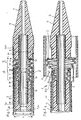
- the endoprosthesis 1 shows a device 2 according to the invention an endoprosthesis 1 is mounted.
- the endoprosthesis 1 is for example braided from stainless steel wires 1a and can be on the outside with one not shown here stretchable shell.
- the length of the endoprosthesis 1 is of course tailored to the intended use and this length can in particular be much greater than shown here.
- the endoprosthesis 1 is in a proximal Area A over the entire circumference of a distal Area of a first outer catheter 3 and in a distal Area B spanned by a second outer catheter 30.
- the two outer catheters 3 and 30 each have a flexible elongated piece of hose 3a or 30a, the each provided with a distal mouth 3b or 30b are.
- the endoprosthesis 1 is thus with its outside in a partial area A under tension on an inside 18 of the first outer catheter 3 and in a partial area B also under tension on an inside 31 of the second Outer catheter 30. Prevent both outer catheters 3 and 30 radial expansion of the endoprosthesis 1.
- a flexible inner catheter 6 is in a continuous lumen 8 of the first outer catheter 3 used and this Inner catheter 6 can have a continuous lumen 15 for receiving it have a guide wire, not shown here.
- the inner catheter 6 has a preferably flexible tip 7, an intermediate piece 9 and a proximal to the intermediate piece 9 arranged pipe section 10.
- the flexible adapter 9 is cylindrical on the outside and has an outside diameter F that is smaller than the outside diameter C of the pipe section 10 and also smaller than the outer diameter H of the tip 7.
- Cross-sectional areas arranged at a distance from one another 16 and 17 of the pipe section 10 and the tip 7 and the inner sides 18 and 31 of the outer catheter 3 or 30 and a cylindrical outer side 19 of the intermediate piece 9 form a hollow cylindrical space 14 in which the mounted endoprosthesis 1 housed in a tensioned state is.
- the endoprosthesis 1 is in the longitudinal direction in the space 14 through the surfaces 16 and 17 and by friction on the two outer catheters 3 and 30 fixed. Instead of the room 14, however, it is also possible in a known manner Endoprosthesis 1 with other means axially on the inner catheter 6 to fix.
- the tip 7 engages with a shoulder 6a in the distal end of the second outer catheter 30 and lies with one Shoulder 5 at the mouth 30b of this catheter. As can be seen overlaps the shoulder 5 of the mouth 30b of the External catheter. This prevents the insertion the device into a vessel 11 of the outer catheter 30 can hurt.
- the inner catheter 6 is at the proximal end according to FIG. 4 provided with a connecting piece 24 known per se, that for injecting contrast agent as well, for example is used to insert a guide wire.
- the first outer catheter 3 is connected at its proximal end to a connection and sealing piece 23, one here Has seal, not shown, which is slidable on the inner catheter 6 is present.
- the connection and sealing piece 23 is in the usual way with a branch 25 and a Cock 26 and a flexible hose 27 provided, the hose line with the lumen 8 of the first outer catheter 3 is connected.
- the second outer catheter 30 is also connected at its proximal end to a connection and sealing piece 32, which is of the same design can be like piece 23, but in adaptation to the larger outer diameter of the catheter 30 accordingly is larger.
- a corresponding hose line 33 is with the lumen of the second outer catheter 30 connected.
- the first outer catheter 3 can thus in the longitudinal direction on the inner catheter 6 and the second outer catheter 30 on the first outer catheter 3 also in Can be telescopically moved in the longitudinal direction.
- the hose piece 30b of the second outer catheter 30 is over its entire Length on the first outer catheter 3 slidably led the strength requirements to the second External catheters 30 are therefore comparatively small.
- the endoprosthesis 1 To mount the endoprosthesis 1, this is on the inner catheter 6 pushed on, the outer catheters 3 and 30 withdrawn at least up to a surface 16. By Advancing the first outer catheter 3 over the endoprosthesis 1 and then by advancing the second Outer catheter 30, the endoprosthesis 1 is folded and tensioned, until finally in the device according to FIG. 1 fixed, and the mouth 30b on the shoulder 5 of the Tip 7 is present.
- the assembled endoprosthesis 1 is now known per se Way with the device 2, for example, into the vessel 11 (Fig. 2) introduced.
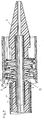
- the second outer catheter 30 on the connection and sealing piece 32 retracted until it is the one shown in FIG Location reached.
- the endoprosthesis 1 is essentially released in section B and can in this Expand area. 2 can the endoprosthesis 1 is fully compressed again, by advancing the second outer catheter 30 again in the position shown in Fig. 1. This is possible because 2, the endoprosthesis 1 in its area A from the first External catheter 3 is held in place by friction.
- the two tube pieces 3b and 30b are preferably made of a plastic that is comparatively good Has sliding properties and is suitable for this purpose also well suited.
- This is preferably plastic Polytetrafluoroethylene.
- An execution is also conceivable in which more than two external catheters are provided, the are telescopically displaceable and the endoprosthesis proportionately spanning.
Claims (10)
- Dispositif pour libérer une endoprothèse auto-extensible (1), comportant un cathéter allongé flexible (3) possédant une extrémité distale et une extrémité proximale et un cathéter intérieur allongé flexible (6), qui est disposé coaxialement par rapport au cathéter extérieur (3) et possède, sur une extrémité distale, une pointe (7) et, sur le côté proximal de cette extrémité, des moyens (14) pour recevoir l'endoprothèse (1), auquel cas pour la fixation de l'endoprothèse (1), le cathéter extérieur (3) peut être repoussé dans sa direction longitudinale par-dessus les moyens (14) et peut être rétracté par-dessus ces moyens pour la libération de l'endoprothèse, caractérisé en ce que coaxialement au cathéter extérieur (3) est disposé, sur ce dernier, un second cathéter extérieur (30), qui peut être appliqué par une embouchure distale (30b) sur la pointe (7) et qui peut être déplacé dans la direction longitudinale sur le premier cathéter extérieur (3), ladite pointe (7) limitant la mobilité axiale du second cathéter extérieur (30) par rapport au premier cathéter extérieur (3) dans la direction distale de telle sorte que lorsqu'une endoprothèse (1) est insérée, le second cathéter extérieur (30) fait saillie distalement par une extrémité distale (30b) au-delà du premier cathéter extérieur (3) de sorte que l'endoprothèse (1) est serrée par une extrémité distale (B) contre une face intérieure (31) du second cathéter extérieur (30) et, par une extrémité proximale (A), contre une face intérieure d'un premier cathéter extérieur (3) et que pour la libération de l'endoprothèse (1), le second cathéter extérieur (30) et le premier cathéter extérieur (3) peuvent être rétractés sur le cathéter intérieur (6) à partir de l'endoprothèse (1).
- Dispositif selon la revendication 1, caractérisé en ce que les deux cathéters extérieurs (3, 30) peuvent être rétractés de l'endoprothèse (1), indépendamment l'un l'autre.
- Dispositif selon la revendication 1 ou 2, caractérisé en ce que le second cathéter extérieur (30) possède un élément de tuyau souple de forme tubulaire (30a), sur lequel est fixé, sur le côté proximal, un élément de raccordement et d'étanchéité (32), qui étanchéifie le second cathéter extérieur (30) par rapport au premier cathéter extérieur (3) et peut être déplacé sur ce dernier.
- Dispositif selon l'une des revendications 1 à 3, caractérisé en ce que le second cathéter extérieur (30) se termine, au niveau de son extrémité distale, par une embouchure de forme circulaire (30b).
- Dispositif selon l'une des revendications 1 à 4, caractérisé en ce que la pointe (7) du cathéter intérieur (6) comporte un épaulement (5), qui fait saillie latéralement hors du second cathéter extérieur (30), au niveau de son extrémité distale.
- Dispositif selon l'une des revendications 1 à 5, caractérisé en ce que le second cathéter extérieur (30) comporte une face intérieure lisse au moins sur son extrémité distale.
- Dispositif selon l'une des revendications 2 à 6, caractérisé en ce que l'élément de tuyau (30a) est réalisé en polytétrafluoroéthylène ou en une matière plastique ayant une propriété de glissement aussi bonne.
- Dispositif selon l'une des revendications 3 à 7, caractérisé en ce que l'épaisseur de paroi de l'élément de tuyau (30a) du second cathéter extérieur (30) correspond essentiellement à l'épaisseur de paroi d'un élément de tuyau du premier cathéter extérieur (3).
- Dispositif selon l'une des revendications 1 à 8, caractérisé en ce que le cathéter intérieur (6) comporte, sur sa face extérieure, un évidement en forme de cylindre circulaire (14) servant à recevoir l'endoprothèse (1).
- Dispositif selon l'une des revendications 1 à 9, caractérisé en ce que le cathéter intérieur (6) possède un élément intermédiaire (9), qui relie la pointe (7) à un élément tubulaire (10) disposé de façon distale et possède un diamètre extérieur (F) qui est inférieur à un diamètre extérieur (C) de l'élément tubulaire (10).
Priority Applications (9)
| Application Number | Priority Date | Filing Date | Title |
|---|---|---|---|
| EP93810398A EP0627201B1 (fr) | 1993-06-02 | 1993-06-02 | Dispositif pour libérer une endoprothèse auto-expansible |
| DK93810398T DK0627201T3 (da) | 1993-06-02 | 1993-06-02 | Anordning til frigørelse af en selvekspanderende endoprotese |
| DE59308805T DE59308805D1 (de) | 1993-06-02 | 1993-06-02 | Vorrichtung zum Freisetzen einer selbstexpandierenden Endoprothese |
| ES93810398T ES2120489T3 (es) | 1993-06-02 | 1993-06-02 | Dispositivo para liberar una endoprotesis auto-expansiva. |
| AT93810398T ATE168550T1 (de) | 1993-06-02 | 1993-06-02 | Vorrichtung zum freisetzen einer selbstexpandierenden endoprothese |
| US08/249,821 US5919204A (en) | 1993-06-02 | 1994-05-26 | Apparatus for releasing a self-expanding endoprosthesis |
| AU63437/94A AU659975B2 (en) | 1993-06-02 | 1994-05-30 | An apparatus for releasing a self-expanding endoprosthesis |
| CA002124909A CA2124909C (fr) | 1993-06-02 | 1994-06-01 | Dispositif de mise en place d'une endoprothese auto-expansible |
| JP6121304A JP2908982B2 (ja) | 1993-06-02 | 1994-06-02 | 自己膨張型の体内人工装具を解放するための装置 |
Applications Claiming Priority (1)
| Application Number | Priority Date | Filing Date | Title |
|---|---|---|---|
| EP93810398A EP0627201B1 (fr) | 1993-06-02 | 1993-06-02 | Dispositif pour libérer une endoprothèse auto-expansible |
Publications (2)
| Publication Number | Publication Date |
|---|---|
| EP0627201A1 EP0627201A1 (fr) | 1994-12-07 |
| EP0627201B1 true EP0627201B1 (fr) | 1998-07-22 |
Family
ID=8214976
Family Applications (1)
| Application Number | Title | Priority Date | Filing Date |
|---|---|---|---|
| EP93810398A Expired - Lifetime EP0627201B1 (fr) | 1993-06-02 | 1993-06-02 | Dispositif pour libérer une endoprothèse auto-expansible |
Country Status (9)
| Country | Link |
|---|---|
| US (1) | US5919204A (fr) |
| EP (1) | EP0627201B1 (fr) |
| JP (1) | JP2908982B2 (fr) |
| AT (1) | ATE168550T1 (fr) |
| AU (1) | AU659975B2 (fr) |
| CA (1) | CA2124909C (fr) |
| DE (1) | DE59308805D1 (fr) |
| DK (1) | DK0627201T3 (fr) |
| ES (1) | ES2120489T3 (fr) |
Cited By (13)
| Publication number | Priority date | Publication date | Assignee | Title |
|---|---|---|---|---|
| US6416541B2 (en) | 1998-07-24 | 2002-07-09 | Micrus Corporation | Intravascular flow modifier and reinforcement device |
| US6475169B2 (en) | 1997-12-05 | 2002-11-05 | Micrus Corporation | Micro-strand cable with enhanced radiopacity |
| US6497671B2 (en) | 1997-12-05 | 2002-12-24 | Micrus Corporation | Coated superelastic stent |
| US6500149B2 (en) | 1998-08-31 | 2002-12-31 | Deepak Gandhi | Apparatus for deployment of micro-coil using a catheter |
| US6506201B2 (en) | 1996-08-23 | 2003-01-14 | Scimed Life Systems, Inc. | Balloon catheter with stent securement means |
| US6616617B1 (en) | 1997-12-05 | 2003-09-09 | Micrus Corporation | Vasoocclusive device for treatment of aneurysms |
| US6656218B1 (en) | 1998-07-24 | 2003-12-02 | Micrus Corporation | Intravascular flow modifier and reinforcement device |
| US6743210B2 (en) | 2001-02-15 | 2004-06-01 | Scimed Life Systems, Inc. | Stent delivery catheter positioning device |
| US7468070B2 (en) | 2004-01-23 | 2008-12-23 | Boston Scientific Scimed, Inc. | Stent delivery catheter |
| US7780680B2 (en) | 2000-02-09 | 2010-08-24 | Micrus Corporation | Apparatus for deployment of micro-coil using a catheter |
| US7887574B2 (en) | 2003-12-23 | 2011-02-15 | Scimed Life Systems, Inc. | Stent delivery catheter |
| US8298256B2 (en) | 2000-02-09 | 2012-10-30 | Micrus Endovascular Corporation | Apparatus and method for deployment of a therapeutic device using a catheter |
| US8709062B2 (en) | 1996-08-23 | 2014-04-29 | Boston Scientific Scimed, Inc. | Stent delivery system having stent securement apparatus |
Families Citing this family (81)
| Publication number | Priority date | Publication date | Assignee | Title |
|---|---|---|---|---|
| US5591172A (en) * | 1991-06-14 | 1997-01-07 | Ams Medinvent S.A. | Transluminal implantation device |
| US5571168A (en) * | 1995-04-05 | 1996-11-05 | Scimed Lifesystems Inc | Pull back stent delivery system |
| ES2131253T3 (es) * | 1995-11-14 | 1999-07-16 | Schneider Europ Gmbh | Dispositivo para la implantacion de una endoprotesis. |
| US6190402B1 (en) | 1996-06-21 | 2001-02-20 | Musc Foundation For Research Development | Insitu formable and self-forming intravascular flow modifier (IFM) and IFM assembly for deployment of same |
| US5944726A (en) * | 1996-08-23 | 1999-08-31 | Scimed Life Systems, Inc. | Stent delivery system having stent securement means |
| US5980530A (en) | 1996-08-23 | 1999-11-09 | Scimed Life Systems Inc | Stent delivery system |
| US6007543A (en) | 1996-08-23 | 1999-12-28 | Scimed Life Systems, Inc. | Stent delivery system with stent securement means |
| US6077273A (en) | 1996-08-23 | 2000-06-20 | Scimed Life Systems, Inc. | Catheter support for stent delivery |
| US6391032B2 (en) | 1996-08-23 | 2002-05-21 | Scimed Life Systems, Inc. | Stent delivery system having stent securement means |
| US5772669A (en) * | 1996-09-27 | 1998-06-30 | Scimed Life Systems, Inc. | Stent deployment catheter with retractable sheath |
| US5968052A (en) | 1996-11-27 | 1999-10-19 | Scimed Life Systems Inc. | Pull back stent delivery system with pistol grip retraction handle |
| US5906619A (en) * | 1997-07-24 | 1999-05-25 | Medtronic, Inc. | Disposable delivery device for endoluminal prostheses |
| US6835185B2 (en) | 1998-12-21 | 2004-12-28 | Micrus Corporation | Intravascular device deployment mechanism incorporating mechanical detachment |
| US6248122B1 (en) | 1999-02-26 | 2001-06-19 | Vascular Architects, Inc. | Catheter with controlled release endoluminal prosthesis |
| CA2359507C (fr) * | 1999-02-26 | 2005-03-29 | Vascular Architects, Inc. | Ensemble catheter avec prothese endoluminale et procede de mise en place |
| US6146415A (en) * | 1999-05-07 | 2000-11-14 | Advanced Cardiovascular Systems, Inc. | Stent delivery system |
| KR100341019B1 (ko) * | 1999-08-18 | 2002-06-20 | 신경민 | 신체의 협착부위를 확장시키는 확장기구 삽입장치 |
| US6322586B1 (en) * | 2000-01-10 | 2001-11-27 | Scimed Life Systems, Inc. | Catheter tip designs and method of manufacture |
| US6602280B2 (en) | 2000-02-02 | 2003-08-05 | Trivascular, Inc. | Delivery system and method for expandable intracorporeal device |
| US6743219B1 (en) | 2000-08-02 | 2004-06-01 | Cordis Corporation | Delivery apparatus for a self-expanding stent |
| US20020016597A1 (en) * | 2000-08-02 | 2002-02-07 | Dwyer Clifford J. | Delivery apparatus for a self-expanding stent |
| GB2370506B (en) * | 2000-10-04 | 2005-02-16 | Biocompatibles Ltd | Catheter tip |
| KR100457630B1 (ko) * | 2001-04-04 | 2004-11-18 | (주) 태웅메디칼 | 형상기억합금을 이용한 가변상태 유지형 확장기구의제조방법과 이에 의해 제조된 확장기구 |
| US6733521B2 (en) | 2001-04-11 | 2004-05-11 | Trivascular, Inc. | Delivery system and method for endovascular graft |
| US20040138734A1 (en) * | 2001-04-11 | 2004-07-15 | Trivascular, Inc. | Delivery system and method for bifurcated graft |
| US6761733B2 (en) | 2001-04-11 | 2004-07-13 | Trivascular, Inc. | Delivery system and method for bifurcated endovascular graft |
| US6645238B2 (en) * | 2001-07-09 | 2003-11-11 | Scimed Life Systems, Inc. | Skids stent delivery system |
| US8252040B2 (en) | 2001-07-20 | 2012-08-28 | Microvention, Inc. | Aneurysm treatment device and method of use |
| US6726714B2 (en) | 2001-08-09 | 2004-04-27 | Scimed Life Systems, Inc. | Stent delivery system |
| WO2003014736A1 (fr) * | 2001-08-10 | 2003-02-20 | Meditech Reserach Limited | Support de liaison solide destine a des molecules biologiques comprenant des glycosaminoglycanes |
| US20100016943A1 (en) | 2001-12-20 | 2010-01-21 | Trivascular2, Inc. | Method of delivering advanced endovascular graft |
| US7264632B2 (en) * | 2002-06-07 | 2007-09-04 | Medtronic Vascular, Inc. | Controlled deployment delivery system |
| US7771463B2 (en) | 2003-03-26 | 2010-08-10 | Ton Dai T | Twist-down implant delivery technologies |
| US20050209672A1 (en) * | 2004-03-02 | 2005-09-22 | Cardiomind, Inc. | Sliding restraint stent delivery systems |
| US8016869B2 (en) | 2003-03-26 | 2011-09-13 | Biosensors International Group, Ltd. | Guidewire-less stent delivery methods |
| AU2004226464A1 (en) | 2003-03-26 | 2004-10-14 | Cardiomind, Inc. | Implant delivery technologies |
| US7876738B2 (en) * | 2004-03-02 | 2011-01-25 | Nokia Corporation | Preventing an incorrect synchronization between a received code-modulated signal and a replica code |
| US20050209671A1 (en) * | 2004-03-02 | 2005-09-22 | Cardiomind, Inc. | Corewire actuated delivery system with fixed distal stent-carrying extension |
| US7651521B2 (en) | 2004-03-02 | 2010-01-26 | Cardiomind, Inc. | Corewire actuated delivery system with fixed distal stent-carrying extension |
| US20050209670A1 (en) * | 2004-03-02 | 2005-09-22 | Cardiomind, Inc. | Stent delivery system with diameter adaptive restraint |
| US8623067B2 (en) | 2004-05-25 | 2014-01-07 | Covidien Lp | Methods and apparatus for luminal stenting |
| US8267985B2 (en) | 2005-05-25 | 2012-09-18 | Tyco Healthcare Group Lp | System and method for delivering and deploying an occluding device within a vessel |
| US20060206200A1 (en) | 2004-05-25 | 2006-09-14 | Chestnut Medical Technologies, Inc. | Flexible vascular occluding device |
| EP1750619B1 (fr) | 2004-05-25 | 2013-07-24 | Covidien LP | Dispositif d'occlusion vasculaire flexible |
| CA2758946C (fr) | 2004-05-25 | 2014-10-21 | Tyco Healthcare Group Lp | Implantation d'endoprotheses vasculaires pour l'anevrysme |
| US8617234B2 (en) | 2004-05-25 | 2013-12-31 | Covidien Lp | Flexible vascular occluding device |
| US20060085057A1 (en) * | 2004-10-14 | 2006-04-20 | Cardiomind | Delivery guide member based stent anti-jumping technologies |
| JP2008516668A (ja) * | 2004-10-14 | 2008-05-22 | カーディオマインド, インコーポレイテッド | 小型管ステント設計 |
| US8273101B2 (en) | 2005-05-25 | 2012-09-25 | Tyco Healthcare Group Lp | System and method for delivering and deploying an occluding device within a vessel |
| WO2006127005A1 (fr) | 2005-05-25 | 2006-11-30 | Chestnut Medical Technologies, Inc. | Systeme et procede destines a distribuer et deployer un dispositif d’occlusion a l’interieur d’un vaisseau |
| US20060276886A1 (en) * | 2005-06-07 | 2006-12-07 | Cardiomind, Inc. | Ten-thousandths scale metal reinforced stent delivery guide sheath or restraint |
| US20070027522A1 (en) * | 2005-06-14 | 2007-02-01 | Chang Jean C | Stent delivery and guidewire systems |
| US20070055339A1 (en) * | 2005-08-23 | 2007-03-08 | George William R | Staged stent delivery systems |
| US20070100414A1 (en) | 2005-11-02 | 2007-05-03 | Cardiomind, Inc. | Indirect-release electrolytic implant delivery systems |
| US8152833B2 (en) | 2006-02-22 | 2012-04-10 | Tyco Healthcare Group Lp | Embolic protection systems having radiopaque filter mesh |
| US7699884B2 (en) * | 2006-03-22 | 2010-04-20 | Cardiomind, Inc. | Method of stenting with minimal diameter guided delivery systems |
| US8052732B2 (en) * | 2006-11-14 | 2011-11-08 | Medtronic Vascular, Inc. | Delivery system for stent-graft with anchoring pins |
| US20080262590A1 (en) * | 2007-04-19 | 2008-10-23 | Medtronic Vascular, Inc. | Delivery System for Stent-Graft |
| US9023094B2 (en) | 2007-06-25 | 2015-05-05 | Microvention, Inc. | Self-expanding prosthesis |
| US8066755B2 (en) | 2007-09-26 | 2011-11-29 | Trivascular, Inc. | System and method of pivoted stent deployment |
| US8663309B2 (en) | 2007-09-26 | 2014-03-04 | Trivascular, Inc. | Asymmetric stent apparatus and method |
| US8226701B2 (en) | 2007-09-26 | 2012-07-24 | Trivascular, Inc. | Stent and delivery system for deployment thereof |
| US10159557B2 (en) | 2007-10-04 | 2018-12-25 | Trivascular, Inc. | Modular vascular graft for low profile percutaneous delivery |
| US8083789B2 (en) | 2007-11-16 | 2011-12-27 | Trivascular, Inc. | Securement assembly and method for expandable endovascular device |
| US8328861B2 (en) | 2007-11-16 | 2012-12-11 | Trivascular, Inc. | Delivery system and method for bifurcated graft |
| US9675482B2 (en) | 2008-05-13 | 2017-06-13 | Covidien Lp | Braid implant delivery systems |
| US8657870B2 (en) | 2009-06-26 | 2014-02-25 | Biosensors International Group, Ltd. | Implant delivery apparatus and methods with electrolytic release |
| US8454682B2 (en) | 2010-04-13 | 2013-06-04 | Medtronic Vascular, Inc. | Anchor pin stent-graft delivery system |
| WO2011136963A1 (fr) | 2010-04-30 | 2011-11-03 | Boston Scientific Scimed, Inc. | Endoprothèse métabolique duodénale |
| US8864811B2 (en) * | 2010-06-08 | 2014-10-21 | Veniti, Inc. | Bi-directional stent delivery system |
| US9301864B2 (en) | 2010-06-08 | 2016-04-05 | Veniti, Inc. | Bi-directional stent delivery system |
| JP2014522263A (ja) | 2011-05-11 | 2014-09-04 | マイクロベンション インコーポレイテッド | 内腔を閉塞するためのデバイス |
| US8992595B2 (en) | 2012-04-04 | 2015-03-31 | Trivascular, Inc. | Durable stent graft with tapered struts and stable delivery methods and devices |
| US9498363B2 (en) | 2012-04-06 | 2016-11-22 | Trivascular, Inc. | Delivery catheter for endovascular device |
| US9155647B2 (en) | 2012-07-18 | 2015-10-13 | Covidien Lp | Methods and apparatus for luminal stenting |
| US9114001B2 (en) | 2012-10-30 | 2015-08-25 | Covidien Lp | Systems for attaining a predetermined porosity of a vascular device |
| US9452070B2 (en) | 2012-10-31 | 2016-09-27 | Covidien Lp | Methods and systems for increasing a density of a region of a vascular device |
| US9943427B2 (en) | 2012-11-06 | 2018-04-17 | Covidien Lp | Shaped occluding devices and methods of using the same |
| US9157174B2 (en) | 2013-02-05 | 2015-10-13 | Covidien Lp | Vascular device for aneurysm treatment and providing blood flow into a perforator vessel |
| EP2813195A1 (fr) * | 2013-06-13 | 2014-12-17 | Cardiatis S.A. | Système de mise en place d'endoprothèse vasculaire |
| EP3122293B1 (fr) | 2014-03-24 | 2019-04-24 | Boston Scientific Scimed, Inc. | Système de pose d'endoprothèse à auto-déploiement |
Family Cites Families (10)
| Publication number | Priority date | Publication date | Assignee | Title |
|---|---|---|---|---|
| US502757A (en) * | 1893-08-08 | Half to henry l | ||
| GB8312650D0 (en) * | 1983-05-07 | 1983-06-08 | Plessey Co Plc | Optical connectors |
| IT1186142B (it) * | 1984-12-05 | 1987-11-18 | Medinvent Sa | Dispositivo di impiantazione transluminale |
| US4665918A (en) * | 1986-01-06 | 1987-05-19 | Garza Gilbert A | Prosthesis system and method |
| EP0257091B1 (fr) * | 1986-02-24 | 1993-07-28 | Robert E. Fischell | Distendeur intravasculaire et systeme d'introduction percutanee |
| US4893623A (en) * | 1986-12-09 | 1990-01-16 | Advanced Surgical Intervention, Inc. | Method and apparatus for treating hypertrophy of the prostate gland |
| US4832055A (en) * | 1988-07-08 | 1989-05-23 | Palestrant Aubrey M | Mechanically locking blood clot filter |
| DE9010130U1 (fr) * | 1989-07-13 | 1990-09-13 | American Medical Systems, Inc., Minnetonka, Minn., Us | |
| US5591172A (en) * | 1991-06-14 | 1997-01-07 | Ams Medinvent S.A. | Transluminal implantation device |
| US5201757A (en) * | 1992-04-03 | 1993-04-13 | Schneider (Usa) Inc. | Medial region deployment of radially self-expanding stents |
-
1993
- 1993-06-02 AT AT93810398T patent/ATE168550T1/de not_active IP Right Cessation
- 1993-06-02 EP EP93810398A patent/EP0627201B1/fr not_active Expired - Lifetime
- 1993-06-02 ES ES93810398T patent/ES2120489T3/es not_active Expired - Lifetime
- 1993-06-02 DK DK93810398T patent/DK0627201T3/da active
- 1993-06-02 DE DE59308805T patent/DE59308805D1/de not_active Expired - Fee Related
-
1994
- 1994-05-26 US US08/249,821 patent/US5919204A/en not_active Expired - Lifetime
- 1994-05-30 AU AU63437/94A patent/AU659975B2/en not_active Ceased
- 1994-06-01 CA CA002124909A patent/CA2124909C/fr not_active Expired - Fee Related
- 1994-06-02 JP JP6121304A patent/JP2908982B2/ja not_active Expired - Fee Related
Cited By (14)
| Publication number | Priority date | Publication date | Assignee | Title |
|---|---|---|---|---|
| US8709062B2 (en) | 1996-08-23 | 2014-04-29 | Boston Scientific Scimed, Inc. | Stent delivery system having stent securement apparatus |
| US6506201B2 (en) | 1996-08-23 | 2003-01-14 | Scimed Life Systems, Inc. | Balloon catheter with stent securement means |
| US6475169B2 (en) | 1997-12-05 | 2002-11-05 | Micrus Corporation | Micro-strand cable with enhanced radiopacity |
| US6497671B2 (en) | 1997-12-05 | 2002-12-24 | Micrus Corporation | Coated superelastic stent |
| US6616617B1 (en) | 1997-12-05 | 2003-09-09 | Micrus Corporation | Vasoocclusive device for treatment of aneurysms |
| US6416541B2 (en) | 1998-07-24 | 2002-07-09 | Micrus Corporation | Intravascular flow modifier and reinforcement device |
| US6656218B1 (en) | 1998-07-24 | 2003-12-02 | Micrus Corporation | Intravascular flow modifier and reinforcement device |
| US6500149B2 (en) | 1998-08-31 | 2002-12-31 | Deepak Gandhi | Apparatus for deployment of micro-coil using a catheter |
| US7780680B2 (en) | 2000-02-09 | 2010-08-24 | Micrus Corporation | Apparatus for deployment of micro-coil using a catheter |
| US7972342B2 (en) | 2000-02-09 | 2011-07-05 | Micrus Corporation | Apparatus for deployment of micro-coil using a catheter |
| US8298256B2 (en) | 2000-02-09 | 2012-10-30 | Micrus Endovascular Corporation | Apparatus and method for deployment of a therapeutic device using a catheter |
| US6743210B2 (en) | 2001-02-15 | 2004-06-01 | Scimed Life Systems, Inc. | Stent delivery catheter positioning device |
| US7887574B2 (en) | 2003-12-23 | 2011-02-15 | Scimed Life Systems, Inc. | Stent delivery catheter |
| US7468070B2 (en) | 2004-01-23 | 2008-12-23 | Boston Scientific Scimed, Inc. | Stent delivery catheter |
Also Published As
| Publication number | Publication date |
|---|---|
| EP0627201A1 (fr) | 1994-12-07 |
| JP2908982B2 (ja) | 1999-06-23 |
| ES2120489T3 (es) | 1998-11-01 |
| CA2124909A1 (fr) | 1994-12-03 |
| ATE168550T1 (de) | 1998-08-15 |
| DE59308805D1 (de) | 1998-08-27 |
| AU659975B2 (en) | 1995-06-01 |
| JPH0751384A (ja) | 1995-02-28 |
| CA2124909C (fr) | 1999-11-16 |
| US5919204A (en) | 1999-07-06 |
| AU6343794A (en) | 1994-12-15 |
| DK0627201T3 (da) | 1999-04-26 |
Similar Documents
| Publication | Publication Date | Title |
|---|---|---|
| EP0627201B1 (fr) | Dispositif pour libérer une endoprothèse auto-expansible | |
| EP0592726B1 (fr) | Cathéter avec un support vasculaire | |
| EP0607468B1 (fr) | Dispositif d'introduction d'un dilatateur | |
| DE69533356T2 (de) | Gerät zum einführen und entfalten von intraluminalen vorrichtungen | |
| DE69825200T2 (de) | Kathetersystem zum Anbringen eines Stent | |
| DE69635967T2 (de) | Schnellaustausch-Stentanbringungsballonkatheter | |
| DE69531143T2 (de) | Kathetersystem mit integrierter Doppelfunktion zur Ballon-Angioplastik und zum Anbringen eines Stents | |
| DE60110371T2 (de) | Vorrichtung zum einbringen einer intraluminalen prothese | |
| DE69921908T2 (de) | Ballonkatheter mit elastischem Füllkörper zum Stützen eines Stents | |
| DE60032056T2 (de) | Katheter zum Anbringen eines Primärstent | |
| DE69816172T2 (de) | Flüssigkeitsgesteuertes Stentanbringungssystem | |
| DE69731560T2 (de) | Stententfaltungskatheter mit zurückschiebbarer hülse | |
| DE69921622T2 (de) | Konvertierbarer katheter mit einem kollabierbaren lumen | |
| EP0843990B1 (fr) | Cathéter à ballon et système d'application d'une endoprothèse | |
| DE69632948T2 (de) | Entfaltungssystem für endoprothetischen Stent oder Transplantat | |
| DE69629599T2 (de) | Endoprothese zur behandlung von bifurkationsstenosen in blutgefässen | |
| EP0479730B1 (fr) | Cathéter dilatateur à ballonnet | |
| DE69925627T2 (de) | Minimal-invasiver revaskularisationsapparat | |
| EP1200018B1 (fr) | Catheter d'insertion pour protheses vasculaires | |
| DE60214973T2 (de) | Gerät zur implantierung eines stents mit flüssigkeitsabgabe | |
| DE60002480T2 (de) | Stenteinbringungssystem | |
| EP0536610B1 (fr) | Dispositif pour la dilatation d'une sténose | |
| DE19828415B4 (de) | Stent für ein Endoskop und System zum Einführen dieses Stents | |
| EP0884028A1 (fr) | Stent radialement dilatable pour le placement dans la zone bifurquée d'un vaisseau corporel | |
| EP1303231B1 (fr) | Dispositif d'ancrage vasculaire |
Legal Events
| Date | Code | Title | Description |
|---|---|---|---|
| PUAI | Public reference made under article 153(3) epc to a published international application that has entered the european phase |
Free format text: ORIGINAL CODE: 0009012 |
|
| 17P | Request for examination filed |
Effective date: 19930607 |
|
| AK | Designated contracting states |
Kind code of ref document: A1 Designated state(s): AT BE CH DE DK ES FR GB IE IT LI NL SE |
|
| 17Q | First examination report despatched |
Effective date: 19951005 |
|
| GRAG | Despatch of communication of intention to grant |
Free format text: ORIGINAL CODE: EPIDOS AGRA |
|
| GRAG | Despatch of communication of intention to grant |
Free format text: ORIGINAL CODE: EPIDOS AGRA |
|
| GRAH | Despatch of communication of intention to grant a patent |
Free format text: ORIGINAL CODE: EPIDOS IGRA |
|
| GRAH | Despatch of communication of intention to grant a patent |
Free format text: ORIGINAL CODE: EPIDOS IGRA |
|
| RAP1 | Party data changed (applicant data changed or rights of an application transferred) |
Owner name: SCHNEIDER (EUROPE) GMBH |
|
| RBV | Designated contracting states (corrected) |
Designated state(s): AT BE CH DE DK ES FR GB IE IT LI NL SE |
|
| GRAA | (expected) grant |
Free format text: ORIGINAL CODE: 0009210 |
|
| AK | Designated contracting states |
Kind code of ref document: B1 Designated state(s): AT BE CH DE DK ES FR GB IE IT LI NL SE |
|
| REF | Corresponds to: |
Ref document number: 168550 Country of ref document: AT Date of ref document: 19980815 Kind code of ref document: T |
|
| REG | Reference to a national code |
Ref country code: CH Ref legal event code: NV Representative=s name: ISLER & PEDRAZZINI AG Ref country code: CH Ref legal event code: EP |
|
| GBT | Gb: translation of ep patent filed (gb section 77(6)(a)/1977) |
Effective date: 19980723 |
|
| REF | Corresponds to: |
Ref document number: 59308805 Country of ref document: DE Date of ref document: 19980827 |
|
| ET | Fr: translation filed | ||
| REG | Reference to a national code |
Ref country code: ES Ref legal event code: FG2A Ref document number: 2120489 Country of ref document: ES Kind code of ref document: T3 |
|
| REG | Reference to a national code |
Ref country code: IE Ref legal event code: FG4D Free format text: GERMAN |
|
| REG | Reference to a national code |
Ref country code: IE Ref legal event code: FD4D |
|
| REG | Reference to a national code |
Ref country code: DK Ref legal event code: T3 |
|
| PGFP | Annual fee paid to national office [announced via postgrant information from national office to epo] |
Ref country code: DK Payment date: 19990511 Year of fee payment: 7 |
|
| PGFP | Annual fee paid to national office [announced via postgrant information from national office to epo] |
Ref country code: AT Payment date: 19990512 Year of fee payment: 7 |
|
| PLBE | No opposition filed within time limit |
Free format text: ORIGINAL CODE: 0009261 |
|
| STAA | Information on the status of an ep patent application or granted ep patent |
Free format text: STATUS: NO OPPOSITION FILED WITHIN TIME LIMIT |
|
| PGFP | Annual fee paid to national office [announced via postgrant information from national office to epo] |
Ref country code: ES Payment date: 19990604 Year of fee payment: 7 |
|
| REG | Reference to a national code |
Ref country code: IE Ref legal event code: FD4D Ref document number: Errata: Incorrectly Country of ref document: IE |
|
| 26N | No opposition filed | ||
| PGFP | Annual fee paid to national office [announced via postgrant information from national office to epo] |
Ref country code: CH Payment date: 19990714 Year of fee payment: 7 |
|
| PGFP | Annual fee paid to national office [announced via postgrant information from national office to epo] |
Ref country code: SE Payment date: 20000519 Year of fee payment: 8 |
|
| PG25 | Lapsed in a contracting state [announced via postgrant information from national office to epo] |
Ref country code: DK Free format text: LAPSE BECAUSE OF NON-PAYMENT OF DUE FEES Effective date: 20000602 Ref country code: AT Free format text: LAPSE BECAUSE OF NON-PAYMENT OF DUE FEES Effective date: 20000602 |
|
| PG25 | Lapsed in a contracting state [announced via postgrant information from national office to epo] |
Ref country code: ES Free format text: THE PATENT HAS BEEN ANNULLED BY A DECISION OF A NATIONAL AUTHORITY Effective date: 20000603 |
|
| PGFP | Annual fee paid to national office [announced via postgrant information from national office to epo] |
Ref country code: BE Payment date: 20000615 Year of fee payment: 8 |
|
| PG25 | Lapsed in a contracting state [announced via postgrant information from national office to epo] |
Ref country code: LI Free format text: LAPSE BECAUSE OF NON-PAYMENT OF DUE FEES Effective date: 20000630 Ref country code: CH Free format text: LAPSE BECAUSE OF NON-PAYMENT OF DUE FEES Effective date: 20000630 |
|
| REG | Reference to a national code |
Ref country code: CH Ref legal event code: PL |
|
| REG | Reference to a national code |
Ref country code: DK Ref legal event code: EBP |
|
| PG25 | Lapsed in a contracting state [announced via postgrant information from national office to epo] |
Ref country code: SE Free format text: LAPSE BECAUSE OF NON-PAYMENT OF DUE FEES Effective date: 20010603 |
|
| PG25 | Lapsed in a contracting state [announced via postgrant information from national office to epo] |
Ref country code: BE Free format text: LAPSE BECAUSE OF NON-PAYMENT OF DUE FEES Effective date: 20010630 |
|
| BERE | Be: lapsed |
Owner name: SCHNEIDER (EUROPE) G.M.B.H. Effective date: 20010630 |
|
| REG | Reference to a national code |
Ref country code: GB Ref legal event code: IF02 |
|
| EUG | Se: european patent has lapsed |
Ref document number: 93810398.3 |
|
| REG | Reference to a national code |
Ref country code: ES Ref legal event code: FD2A Effective date: 20020304 |
|
| PG25 | Lapsed in a contracting state [announced via postgrant information from national office to epo] |
Ref country code: IT Free format text: LAPSE BECAUSE OF NON-PAYMENT OF DUE FEES;WARNING: LAPSES OF ITALIAN PATENTS WITH EFFECTIVE DATE BEFORE 2007 MAY HAVE OCCURRED AT ANY TIME BEFORE 2007. THE CORRECT EFFECTIVE DATE MAY BE DIFFERENT FROM THE ONE RECORDED. Effective date: 20050602 |
|
| PGFP | Annual fee paid to national office [announced via postgrant information from national office to epo] |
Ref country code: IE Payment date: 20070425 Year of fee payment: 15 |
|
| PGFP | Annual fee paid to national office [announced via postgrant information from national office to epo] |
Ref country code: NL Payment date: 20070507 Year of fee payment: 15 |
|
| PGFP | Annual fee paid to national office [announced via postgrant information from national office to epo] |
Ref country code: DE Payment date: 20070629 Year of fee payment: 15 |
|
| PGFP | Annual fee paid to national office [announced via postgrant information from national office to epo] |
Ref country code: GB Payment date: 20070511 Year of fee payment: 15 |
|
| PGFP | Annual fee paid to national office [announced via postgrant information from national office to epo] |
Ref country code: FR Payment date: 20070605 Year of fee payment: 15 |
|
| GBPC | Gb: european patent ceased through non-payment of renewal fee |
Effective date: 20080602 |
|
| NLV4 | Nl: lapsed or anulled due to non-payment of the annual fee |
Effective date: 20090101 |
|
| REG | Reference to a national code |
Ref country code: IE Ref legal event code: MM4A |
|
| REG | Reference to a national code |
Ref country code: FR Ref legal event code: ST Effective date: 20090228 |
|
| PG25 | Lapsed in a contracting state [announced via postgrant information from national office to epo] |
Ref country code: IE Free format text: LAPSE BECAUSE OF NON-PAYMENT OF DUE FEES Effective date: 20080602 Ref country code: DE Free format text: LAPSE BECAUSE OF NON-PAYMENT OF DUE FEES Effective date: 20090101 |
|
| PG25 | Lapsed in a contracting state [announced via postgrant information from national office to epo] |
Ref country code: NL Free format text: LAPSE BECAUSE OF NON-PAYMENT OF DUE FEES Effective date: 20090101 |
|
| PG25 | Lapsed in a contracting state [announced via postgrant information from national office to epo] |
Ref country code: GB Free format text: LAPSE BECAUSE OF NON-PAYMENT OF DUE FEES Effective date: 20080602 |
|
| PG25 | Lapsed in a contracting state [announced via postgrant information from national office to epo] |
Ref country code: FR Free format text: LAPSE BECAUSE OF NON-PAYMENT OF DUE FEES Effective date: 20080630 |