EP0625768A2 - Automatisches Gebührenerfassungssystem - Google Patents
Automatisches Gebührenerfassungssystem Download PDFInfo
- Publication number
- EP0625768A2 EP0625768A2 EP94103707A EP94103707A EP0625768A2 EP 0625768 A2 EP0625768 A2 EP 0625768A2 EP 94103707 A EP94103707 A EP 94103707A EP 94103707 A EP94103707 A EP 94103707A EP 0625768 A2 EP0625768 A2 EP 0625768A2
- Authority
- EP
- European Patent Office
- Prior art keywords
- vehicle
- collection system
- vehicles
- infrared light
- fee collection
- Prior art date
- Legal status (The legal status is an assumption and is not a legal conclusion. Google has not performed a legal analysis and makes no representation as to the accuracy of the status listed.)
- Granted
Links
Images


Classifications
-
- G—PHYSICS
- G07—CHECKING-DEVICES
- G07B—TICKET-ISSUING APPARATUS; FARE-REGISTERING APPARATUS; FRANKING APPARATUS
- G07B15/00—Arrangements or apparatus for collecting fares, tolls or entrance fees at one or more control points
- G07B15/06—Arrangements for road pricing or congestion charging of vehicles or vehicle users, e.g. automatic toll systems
- G07B15/063—Arrangements for road pricing or congestion charging of vehicles or vehicle users, e.g. automatic toll systems using wireless information transmission between the vehicle and a fixed station
Definitions
- the invention relates to an automatic toll collection system (AGE system) for the road use of vehicles which have an on-board device with a communication device, a vehicle transceiver and an electronic wallet in the form of a processor card, a so-called smart card, with the Street-based payment stations that carry out data exchange with at least one wireless communication device installed on or above the street and debit a usage fee while maintaining the anonymity of the vehicle user.
- AGE system automatic toll collection system
- EP-0 413 948-A1 describes a system for optical data transmission, preferably for the automatic payment of road tolls, in which contactless, i.e. wirelessly, the charges can be collected.
- an optical system is proposed for the data transmission, which depicts optical active surfaces that are specifically aligned with the respective lanes. This requires a complex, constructive design and is not suitable for fast and extensive data traffic between vehicles and a payment station in the case of fast-flowing traffic because of the relatively short contact time as a result.
- a localization device which outputs the position of the vehicle currently communicating on the basis of a vehicle transceiver short-term optical signal is determined by assigning the temporary identifier of the vehicle currently communicating, which is known from the communication protocol, to this optical signal.
- the additionally emitted optical signal is formed by an infrared light flash, which is emitted on request from the payment station.
- the vehicle localization device is expediently formed by an infrared light-sensitive video camera, which uses a computer-controlled evaluation to determine the position of this vehicle on the basis of the optical image and to assign it accordingly (correlated).
- the debit is expediently carried out within a specific communication area, the debit being confirmed on the part of the vehicle and documented on the processor card in order to have verifiable information about the debit carried out when a check is carried out later. It is particularly advantageous to acknowledge the debit with the optical signal, the infrared flash.
- a vehicle detection device for all vehicles is arranged at the payment station and is coordinated with the vehicle localization device. In this way, those vehicles that have not issued an acknowledgment signal can be determined, identified and registered, for example with generally known photographic detection systems.
- a video surveillance camera with image recording and image evaluation can advantageously be provided for the vehicle detection device.
- the vehicle detection device can be formed by a known traffic radar device which detects the individual vehicles separately according to the lane.
- the non-payers are taken with a film or video camera for fixed or moving images, i.e. registered with a known photographic detection system, the exact assignment to the vehicle being carried out with the traffic radar device.
- the data exchange can take place with the help of microwave transmission technology. However, it is advantageously provided that the data transmission is carried out using the Perform infrared light transmission.
- the infrared light transmission known from a traffic control and information system (EURO-SCOUT) can be used.
- an electronic video camera is arranged at the paying station, which preferably locates the vehicles when the paying station requests the vehicle transceiver to send a message as proof of correct payment. While the communication system is receiving this message, the video camera is activated to determine the position of the paying transeiver. No separate infrared light flash is required, but this is very advantageous for accurate and reliable localization.
- the active transmission diodes of a vehicle transceiver are thus detected as a light source with the aid of the infrared-sensitive camera, which is expediently attached directly next to the infrared station antenna or IR transmitting and receiving device.
- An optical filter is installed in the beam path of the camera, which only allows light with the wavelength of the infrared rays used.
- the infrared transmitter diodes of the vehicle transceiver are arranged in a very specific form, which can be easily found by image evaluation and can be safely delimited against interference sources.
- a further advantageous embodiment is given in that the Exposure time of the electronic camera is adapted to the transmission phase of the vehicle transceiver, a single vehicle transceiver being specifically requested to be sent by the payment station as part of the transmission protocol.
- Another measure strongly suppresses static light sources using a differential technique. For this purpose, two images are taken during and immediately after the transmission activity and a difference image is formed therefrom, so that the disturbing light sources are largely suppressed and only the transmission diodes for the infrared flash or IR transmission can be clearly recognized.
- the directional information can be converted into absolute coordinates from the camera image obtained with the infrared light-sensitive video camera, in addition to the location and the orientation of the camera, information such as installation height of the transceiver being used.
- the distance from the transceiver can be calculated from the visual size of the transceiver in the camera image.
- An average installation height of the transceiver is provided for the same vehicle classes.
- the type of vehicle, i.e. the vehicle class can be transferred from the vehicle to the payment station when data is exchanged. It is also conceivable to have the individual installation position of the transceiver transferred from the vehicle to the payment station.
- the payment station ZS has an infrared beacon IRB on the left and right side of the signal bridge SB, which is part of an infrared communication device (IRK).
- the two infrared beacons IRB illuminate a certain communication area KB in the direction of travel.
- An infrared video camera IRV which is part of an infrared light localization device IRL, a traffic radar device with a radar detector RD and a normal video camera NV, which is part of a vehicle identification and registration device FIR, are on the signal bridge SB.
- These devices are connected to a control and evaluation device SAE, where all the data processing and correlation takes place. This is shown in principle in Fig.2.
- the data exchange between the payment station ZS and the individual vehicles is handled via the infrared beacons IRB.
- high-quality encryption is required (crypto module).
- the beacon control BS of the infrared communication device IRK controls the handling with the vehicle and the control and evaluation device SAE.
- a successful debit is confirmed with an acknowledgment signal QS, which is also used for the optical Signaling from the vehicle transceiver is used. This is indicated by the trigger pulse TI, which informs the infrared localization device IRL of this.
- the infrared localization device IRL or the vehicle localization device FZL detects the position of the vehicle which has paid and also communicates this to the correlation device COR of the control and evaluation device SAE.
- a traffic radar device ie a vehicle detection device FZD and the associated radar detector RD
- the position of the correlation device COR is communicated to the control and evaluation device SAE. In this way it is possible to recognize the positions of the vehicles that have paid and those of the non-payers and to have them available for the precise registration, identification and registration of the non-payers.
- a vehicle identification and registration device FRI is provided, which is able to record traffic offenders with a normal video camera NV, a video control unit VS and a video recorder REC.
- a monitor MON is provided in the vehicle identification and registration device for visualization.
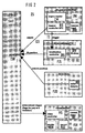
- the control and evaluation device SAE informs the vehicle identification and registration device FIR which vehicles have paid and which have not paid within a communication limit KG and which must now be identified and registered. This is illustrated in Figure 3.
- the payment station ZS is shown in a top view, with three lanes SB1 to SB 3 in one direction of a car road AS, on which three vehicles FZ1 to FZ3 are located.
- the infrared beacons IRB on the left and right of the AS road light up a specific communication area KB off.
- the infrared video camera IRV, the radar detector RD and the normal video camera NV are arranged approximately in the middle of the gantry bridge SB and cover the total area in front of the payment station ZS. It is also shown in FIG. 3 how the infrared communication device IRK recognizes the vehicle that is actually unknown to it as a vehicle that has paid for it.
- the infrared localization device IRL recognizes the position of this vehicle FZ1 on the basis of the optical signal OS which the vehicle FZ1 emits.
- the vehicle detection device FZD uses the traffic radar device RD here to recognize the three vehicles FZ1 to FZ3, which are clearly illustrated in the vehicle detection device FZD and are designated by 6, 7 and 8.
- the vehicle identification and registration device FIR visualizes this traffic situation with the aid of a normal video camera NV and also shows the three vehicles 6, 7 and 8. As indicated in FIG.
- the data of the three or COR correlates four devices, so that in the pictorial representation in the vehicle identification and registration device FRI the vehicle FZ1 is shown as having paid with the number 7, the vehicle FZ2 which has reached the communication limit KG is shown as a non-payer with the number 6 , and the third vehicle FZ3, which is still in the communication area KB, is shown as not yet completed with the number 8.
Abstract
Description
- Die Erfindung bezieht sich auf ein automatisches Gebührenerfassungssystem (AGE-System) für die Straßenbenutzung von Fahrzeugen, die ein Bordgerät mit einer Kommunikationseinrichtung, einem Fahrzeug-Transceiver und einer elektronischen Geldbörse in Form einer Prozessor-Karte, einer sogenannten Smart Card aufweisen, mit an den Straßen angeordneten Zahlstationen, die mit zumindest einer an oder über der Straße angebrachten drahtlosen Kommunikationseinrichtung einen Datenaustausch durchführen und eine Benutzungsgebühr unter Wahrung der Anonymität des Fahrzeugbenutzers abbuchen.
- Gebührenerfassungssysteme für die Straßenbenutzung sind an sich bekannt, insbesondere als sogenannte geschlossene Systeme. Sie gewinnen zunehmend an Bedeutung, weil in verstärktem Maße streckenbezogene Straßenbenutzungsgebühren von vielen Verkehrs- und Umweltpolitikern gefordert werden. Allerdings stößt die Einführung in bisher mautfreien Ländern auf viele Schwierigkeiten. Für hochbelastete Straßennetze kommt dafür nur ein automatisches Gebührenerfassungssystem in Frage, das den Verkehrsfluß nicht behindert und auf dem vorhandenen Straßennetz wirtschaftlich errichtet und betrieben werden kann.
- Beispielsweise ist in der DE-PS 38 33 716 C2 ein Straßenbenutzungsgebühr-Kollektorautomat beschrieben, bei dem als Aufzeichnungsträger für den Gebühreneinzug mittels des Bankkontos der Straßenbenutzer eine IS-Karte verwendet wird. Bei dem bekannten Kollektorautomat ist es ein erheblicher Nachteil, daß der Fahrzeughalter bzw. -Fahrer nicht anonym bleibt. Des weiteren ist es nachteilig, daß die Erfassung der Straßenbenutzungsgebühr nur bei stehenden, in einer dafür vorgesehenen Zahlspur befindlichen Fahrzeugen möglich ist.
- Für eine Gebührenerfassung bei fließendem, mehrspurigem Verkehr ist eine genaue Lokalisation des Fahrzeugs erforderlich, welches gerade seine Straßenbenutzungsgebühr entrichten soll. In der EP-0 413 948 - Al ist ein System zur optischen Datenübertragung, vorzugsweise für die automatische Entrichtung von Straßennutzungsgebühren beschrieben, bei dem berührungslos, d.h. drahtlos, die Gebühren erfaßt werden können. Dazu ist für die Datenübertragung ein optisches System vorgeschlagen, welches speziell auf jeweiligen Fahrspuren ausgerichtete optische Wirkflächen abbildet. Dies erfordert eine aufwendige, konstruktive Ausgestaltung und ist für einen schnellen und umfangreichen Datenverkehr zwischen Fahrzeugen und einer Zahlstation bei schnell fließendem Verkehr wegen der dadurch verhältnismäßig kurzen Kontaktzeit nicht geeignet.
- Aufgabe der Erfindung ist es daher, bei einem automatischen Gebührenerfassungssystem eine sichere, zuverlässige Kommunikation zwischen den Fahrzeugen und der Zahlstation auf mehrspurigen Straßen bei nahezu unverminderter Fahrzeuggeschwindigkeit und auch bei evtl. auftretenden Spurwechsel zu gewährleisten sowie eine Lokalisierung des kommunizierenden Fahrzeugs zu ermöglichen, um Fahrzeuge, die bezahlt haben, und nicht zahlende Fahrzeuge zu erkennen.
- Diese Aufgabe wird bei einem eingangs beschriebenen automatischen Gebührenerfassungssystem mit den Merkmalen des Anspruchs 1 gelöst.
- Erfindungsgemäß wird zur genauen Lokalisierung des Fahrzeugs vorgeschlagen, zusätzlich zur Kommunikationseinrichtung der Zahlstation eine Lokalisierungseinrichtung anzuordnen, die die Position des gerade kommunizierenden Fahrzeugs aufgrund eines vom Fahrzeugtransceiver abgegeben,
kurzzeitigen optischen Signals ermittelt, indem das aus dem Kommunikationsprotokoll bekannte temporäre Kennzeichen des gerade kommunizierenden Fahrzeugs diesem optischen Signal zugeordnet wird. - In einer vorteilhaften Ausgestaltung der Erfindung wird das zusätzlich abgegebene optische Signal von einem Infrarot-Lichtblitz gebildet, welcher auf eine Aufforderung hin seitens der Zahlstation abgegeben wird. Dabei ist zweckmäßigerweise die Fahrzeuglokalisierungs-Einrichtung von einer infrarotlichtempfindlichen Videokamera gebildet, die mittels einer rechnergesteuerten Auswertung die Position dieses Fahrzeugs aufgrund der optischen Abbildung ermittelt und entsprechend zuordnet (korreliert).
- Zweckmäßigerweise erfolgt die Abbuchung innerhalb eines bestimmten Kommunikationsbereichs, wobei die erfolgte Abbuchung seitens des Fahrzeugs quittiert und auf der Prozessorkarte dokumentiert wird, um bei einer evtl. später durchgeführten Kontrolle beweisfähige Angaben über die durchgeführte Abbuchung zu haben. Dabei ist es besonders vorteilhaft, die erfolgte Abbuchung mit dem optischen Signal, dem Infrarotblitz, zu quittieren.
- Diese erfindungsgemäßen Maßnahmen haben den Vorteil, daß der Autofahrer daran gehindert wird, beispielsweise durch Entfernen oder Außerbetriebsetzen des Fahrzeugtransceivers jede Kommunikation und damit auch jede Bezahlung zu vermeiden. Dazu ist ein von der Gebührenerfassung unabhängiges Kontrollsystem mit einem geeigneten Fahrzeugdetektor erforderlich, um zu prüfen, ob alle detektierten Fahrzeuge auch einen zahlenden Transeiver aufweisen. Mit der erfindungsgemäßen Fahrzeug-Lokalisierungseinrichtung sind alle Fahrzeuge bekannt, die ordnungsgemäß ihre Gebühr entrichtet haben.
- Um Nichtzahler, sei es weil sie an ihrer Abbuchungseinrichtung manipuliert haben oder sei es, weil sie mit keinem derartigen Gerät ausgerüstet sind, ist in Weiterbildung der Erfindung an der Zahlstation eine Fahrzeugdetektionseinrichtung für sämtliche Fahrzeuge angeordnet, die mit der Fahrzeuglokalisierungseinrichtung koordiniert ist. Damit können diejenigen Fahrzeuge, die kein Quittungssignal abgegeben haben, ermittelt, identifiziert und registriert werden, beispielsweise mit allgemein bekannten fotografischen Erfassungssystemen.
- In vorteilhafter Weise kann für die Fahrzeugdetektionseinrichtung eine Videoüberwachungskamera mit Bildaufzeichnung und Bildauswertung vorgesehen sein. In einer weiteren Ausgestaltung der Erfindung kann die Fahrzeugdetektionseinrichtung von einem bekannten Verkehrsradargerät gebildet sein, welches die einzelnen Fahrzeuge getrennt nach Fahrspur detektiert. Die Nichtzahler werden mit einer Film- oder Videokamera für feste oder bewegte Bilder, d.h. mit einem bekannten fotografischen Erfassungssystem registriert, wobei die exakte Zuordnung zu dem Fahrzeug mit dem Verkehrsradargerät erfolgt.
- Der Datenaustausch kann mit Hilfe der Mikrowellenübertragungstechnik erfolgen. In vorteilhafter Weise ist jedoch vorgesehen, die Datenübertragung mit Hilfe der Infrarot-Lichtübertragung durchzuführen. Dabei kann die aus einem Verkehrsleit- und Informationssystem (EURO-SCOUT) bekannte Infrarotlichtübertragung verwendet werden.
- Bei dem Datenaustausch zwischen den Fahrzeugen und der Zahlstelle mit Hilfe der Infrarotlichtübertragung ist eine elektronische Videokamera an der Zahlstation angeordnet, die bevorzugt dann die Fahrzeuge lokalisiert, wenn die Zahlstation den Fahrzeugtransceiver auffordert, eine Nachricht als Nachweis für eine korrekte Bezahlung zu senden. Während das Kommunikationssystem diese Nachricht empfängt, wird die Videokamera aktiv, um die Position des zahlenden Transeivers zu ermitteln. Dabei ist kein separater Infrarot-Lichtblitz erforderlich, der jedoch für eine genaue und zuverlässige Lokalisierung sehr vorteilhaft ist. Damit werden mit Hilfe der infrarotempfindlichen Kamera, die zweckmäßigerweise unmittelbar neben der Infrarot-Stationsantenne bzw. IR-Sende- und Empfangseinrichtung angebracht ist, die aktiven Sendedioden eines Fahrzeugtranseivers als Lichtquelle erfaßt.
- Zur Unterdrückung von Störlicht, welches durch Sonnenreflexionen, Scheinwerfer oder Blinker hervorgerufen werden kann, werden in Weiterbildung der Erfindung im folgenden verschiedene Maßnahmen vorgeschlagen. Im Strahlengang der Kamera ist ein optisches Filter angebracht, welches nur Licht mit der Wellenlänge der verwendeten Infrarotstrahlen durchläßt. Die Infrarotsendedioden des Fahrzeugtranseivers werden in einer ganz bestimmten Form angeordnet, die sich per Bildauswertung leicht wiederfinden und gegen Störquellen sicher abgrenzen läßt. Eine weitere vorteilhafte Ausgestaltung ist dadurch gegeben, daß die Belichtungszeit der elektronischen Kamera an die Sendephase des Fahrzeugtransceivers angepaßt ist, wobei im Rahmen des Übertragungsprotokolls ein einzelner Fahrzeugtransceiver von der Zahlstation gezielt zum Senden aufgefordert wird. Mit einer weiteren Maßnahme werden statische Lichtquellen durch eine Differenztechnik stark unterdrückt. Dazu werden während und unmittelbar nach der Sendeaktivität zwei Bilder aufgenommen und daraus ein Differenzbild gebildet, so daß die störenden Lichtquellen weitgehend unterdrückt sind und lediglich die Sendedioden für den Infrarotblitz bzw. die IR-Übertragung eindeutig erkennbar ist.
- Aus dem mit der infrarotlichtempfindlichen Videokamera gewonnenen Kamerabild kann die Richtungsinformation in absolute Koordinaten umgerechnet werden, wobei neben dem Standort und der Ausrichtung der Kamera Informationen, wie beispielsweise Einbauhöhe des Transceivers, ausgenützt werden. So kann aus der visuellen Größe des Transceivers im Kamerabild der Abstand zum Transceiver berechnet werden. Dabei ist eine mittlere Einbauhöhe des Transceivers für gleiche Fahrzeugklassen vorgesehen. Die Art des Fahrzeugs, d.h. die Fahrzeugklasse, kann beim Datenaustausch vom Fahrzeug zur Zahlstation mit übertragen werden. Ebenso ist es denkbar, die individuelle Einbaulage des Transceivers vom Fahrzeug der Zahlstation mit übertragen zu lassen.
- Im folgenden wird die Erfindung anhand der Zeichnung kurz erläutert.
- Fig. 1 zeigt eine Zahlstation an einer dreispurigen Autostraße,
- Fig. 2 schematisch einen prinzipiellen Aufbau für eine automatische Gebührenerfassung und Fahrzeugkontrolle und
- Fig. 3 eine prinzipielle Darstellung für die Fahrzeuglokalisation und -detektion, sowie Fahrzeugidentifizierung und -registrierung an einer mehrspurigen Zahlstation.
- In der Fig. 1 ist in perspektivischer Darstellung schematisch eine Autostraße AS mit drei Fahrspuren SP1 bis SP3 in einer Fahrtrichtung mit einer Signalbrücke SB gezeigt. Die Zahlstation ZS weist bei diesem Ausführungsbeispiel auf der linken und rechten Seite der Signalbrücke SB jeweils eine Infrarotbake IRB auf, die Teil einer Infrarotkommunikationseinrichtung (IRK) ist. Die beiden Infrarotbaken IRB leuchten in Fahrtrichtung einen bestimmten Kommunikationsbereich KB aus. An der Signalbrücke SB ist eine Infrarot-Videokamera IRV, die Teil einer Infrarotlicht-Lokalisationseinrichtung IRL ist, ein Verkehrsradargerät mit einem Radardetektor RD und eine normale Videokamera NV, die Teil einer Fahrzeugidentifizierungs- und Registrierungseinrichtung FIR ist, auf. Diese Einrichtungen sind mit einer Steuer- und Auswerteeinrichtung SAE verbunden, wo die gesamte Datenverarbeitung und Korrelation erfolgt. Dies ist prinzipiell in der Fig.2 dargestellt.
- Mit Hilfe der Infrarot-Kommunikationseinrichtung IRK wird über die Infrarotbaken IRB der Datenaustausch zwischen der Zahlstation ZS und den einzelnen Fahrzeugen abgewickelt. Um das Guthaben auf der Prozessorkarte betrugssicher verwalten zu können, ist eine hochwertige Verschlüsselung erforderlich (Crypto-Modul). Die Bakensteuerung BS der Infrarot-Kommunikationseinrichtung IRK steuert die Abwicklung mit dem Fahrzeug und der Steuer- und Auswerteeinrichtung SAE. Wie bereits oben erwähnt, wird eine erfolgreich durchgeführte Abbuchung mit einem Quittungssignal QS bestätigt, das gleichzeitig für die optische Signalgabe vom Fahrzeugtranseiver verwendet wird. Dies ist mit dem Triggerimpuls TI angedeutet, der der Infrarot-Lokalisationseinrichtung IRL dies mitteilt. Die Infrarot-Lokalisationseinrichtung IRL bzw. die Fahrzeuglokalisationseinrichtung FZL erfaßt die Position des Fahrzeugs, welches bezahlt hat und teilt dies ebenfalls der Korrelationseinrichtung COR der Steuer- und Auswerteeinrichtung SAE mit. Um die Fahrzeuge, die nicht bezahlt haben, zu erfassen, werden mit einem Verkehrsradargerät, d.h. einer Fahrzeugdetektionseinrichtung FZD und den zugehörigen Radardetektor RD, sämtliche Fahrzeuge erfaßt und deren Position der Korrelationseinrichtung COR der Steuer- und Auswerteeinrichtung SAE mitgeteilt. Auf diese Weise ist es möglich, die Positionen der Fahrzeuge, die bezahlt haben, und die der Nichtzahler zu erkennen und für eine genaue Erfassung, Identifizierung und Registrierung der Nichtzahler zur Verfügung zu haben. Zu diesem Zweck ist eine Fahrzeugidentifizierungs- und Registrierungseinrichtung FRI vorgesehen, die mit einer normalen Videokamera NV einer Videosteuerung VS und einem Videorecorder REC die Verkehrssünder festzuhalten vermag. Zur Visualisierung ist in der Fahrzeugidentifizierungs- und Registrierungseinrichtung ein Monitor MON vorgesehen. Von der Steuer- und Auswerteeinrichtung SAE wird der Fahrzeugidentifizierungs-und Registrierungseinrichtung FIR mitgeteilt, welche Fahrzeuge bezahlt haben und welche innerhalb einer Kommunikationsgrenze KG nicht bezahlt haben und nun identifiziert und registriert werden müssen. Dies ist in Fig. 3 veranschaulicht.
- In Fig. 3 ist in einer Draufsicht die Zahlstation ZS gezeigt, mit drei Fahrspuren SB1 bis SB 3 in einer Richtung einer Autostraße AS, auf der sich drei Fahrzeuge FZ1 bis FZ3 befinden. Die Infrarotbaken IRB links und rechts der Autostraße AS leuchten einen bestimmten Kommunikationsbereich KB aus. Etwa in der Mitte der Schilderbrücke SB sind die Infrarot-Videokamera IRV, der Radardetektor RD und die Normal-Videokamera NV angeordnet, die die Gesamtfläche vor der Zahlstation ZS erfassen. Ferner ist in der Fig. 3 gezeigt, wie die Infrarot-Kommunikationseinrichtung IRK das für sie eigentlich unbekannte Fahrzeug als bezahlt habendes Fahrzeug erkennt. Aufgrund des optischen Signals OS, das das Fahrzeug FZ1 abgibt, erkennt die Infrarot-Lokalisationseinrichtung IRL die Position dieses Fahrzeugs FZ1. Die Fahrzeugdetektionseinrichtung FZD erkennt mit Hilfe des Verkehrsradargerätes RD hier die drei Fahrzeuge FZ1 bis FZ3, die in der Fahrzeugdetektionseinrichtung FZD anschaulich dargestellt und mit 6,7 und 8 bezeichnet sind. Die Fahrzeug-Identifizierungs- und Registrierungseinrichtung FIR visualisiert mit Hilfe einer normalen Videokamera NV dieses Verkehrsgeschehen und zeigt ebenfalls die drei Fahrzeuge 6,7 und 8. Wie in Fig. 2 angedeutet, werden in der Steuer- und Auswerteeinrichtung SAE die Daten der drei bzw. vier Einrichtungen korreliert COR, so daß in der bildlichen Darstellung in der Fahrzeugidentifizierungs-und Registrierungseinrichtung FRI das Fahrzeug FZ1 als bezahlt habendes mit der Nummer 7 dargestellt ist, das Fahrzeug FZ2, welches die Kommunikationsgrenze KG erreicht hat, als Nichtzahler mit der Nummer 6 gezeigt ist, und das dritte Fahrzeug FZ3, welches sich noch im Kommunikationsbereich KB befindet, als noch nicht erledigt mit der Nummer 8 bezeichnet dargestellt ist.
Claims (14)
- Automatisches Gebührenerfassungssystem für Straßenbenutzung von Fahrzeugen, die ein Bordgerät mit einer Kommunikationseinrichtung, einem Fahrzeugtransceiver und einer elektronischen Geldbörse in Form einer Prozessor-Karte aufweisen, mit an den Straßen angeordneten Zahlstationen, die mit zumindest einer an oder über der Straße angebrachten drahtlosen Kommunikationseinrichtung einen Datenaustausch durchführen und eine Benutzungsgebühr unter Wahrung der Anonymität des Fahrzeugbenutzers abbuchen,
dadurch gekennzeichnet, daß zusätzlich zur Kommunikationseinrichtung (IRK) der Zahlstation (ZS) eine Fahrzeug-Lokalisierungseinrichtung (FZL) angeordnet ist, die die Position des gerade kommunizierenden Fahrzeugs (FZ) aufgrund eines vom Fahrzeugtransceiver abgegebenen, kurzzeitigen optischen Signals (OS) ermittelt, indem das aus dem Kommunikationsprotokoll bekannte temporäre Kennzeichen diesem optischen Signal (OS) zugeordnet wird. - Automatisches Gebührenerfassungssystem nach Anspruch 1,
dadurch gekennzeichnet, daß das optische Signal (OS) von einem Infrarot-Lichtblitz gebildet wird, der auf Aufforderung durch die Zahlstation (ZS) abgegeben wird, und daß die Fahrzeug-Lokalisierungseinrichtung (FZL) von einer infrarotlichtempfindlichen Videokamera (IRV) gebildet ist, die mittels rechnergesteuerter Auswertung die Position dieses Fahrzeugs (FZ1) ermittelt. - Automatisches Gebührenerfassungssystem nach Anspruch 1,
dadurch gekennzeichnet, daß die Abbuchung innerhalb eines bestimmten Kommunikationsbereichs (KE) bzw. Kommunikationsgrenze (KG) durchgeführt wird, und daß die Abbuchung mit einem Quittungssignal (QS) quittiert sowie auf der Prozessorkarte dokumentiert wird. - Automatisches Gebührenerfassungssystem nach Anspruch 2 oder 3, dadurch gekennzeichnet, daß bei erfolgter Abbuchung mit Quittungssignal (QS) auch das separate optische Signal (OS) abgegeben wird.
- Automatisches Gebührenerfassungssystem nach Anspruch 4, dadurch gekennzeichnet, daß die Zahlstation (ZS) eine Fahrzeug-Detektionseinrichtung (FZD) für sämtliche Fahrzeuge (FZ1,2,3 ...), die sich im Kommunikations- bzw. Zahlungsbereich (KB bzw. KG) befinden, aufweist und mit der Fahrzeug-Lokalisationseinrichtung (FZL) koordiniert (COR) ist, und daß diejenigen Fahrzeuge (FZ2), die kein Quittungssignal (QS) abgegeben haben, mittels der Fahrzeug-Lokalisierungs- und Fahrzeug-Detektionseinrichtung (FZL, FZD) ermittelt, identifiziert und registriert (FIR) werden.
- Automatisches Gebührenerfassungssystem nach Anspruch 5, dadurch gekennzeichnet, daß die Fahrzeug-Detektionseinrichtung (FZD) von einer Videoüberwachungskamera (NV) mit Bildaufzeichnung und -Auswertung (VS und REC bzw. FIR) gebildet ist.
- AutomatischesGebührenerfassungssystem nach Anspruch 5, dadurch gekennzeichnet, daß die Fahrzeug-Detektionseinrichtung (FZD) von einem Verkehrsradargerät (RD), welches die einzelnen Fahrzeuge (FZ1,2,3,...) getrennt nach Fahrspuren (SP1,2,3,...) detektiert, gebildet ist, und zusätzlich eine zugeordnete und koordinierte Fahrzeug-Identifizierungs- und Registrierungseinrichtung (FIR) für Nichtzahler (FZ2 bzw. 6) aufweist.
- Automatisches Gebührenerfassungssystem nach einem der vorhergehenden Ansprüche,
dadurch gekennzeichnet, daß die Kommunikationseinrichtungen der Zahlstation und der Fahrzeuge mit Mikrowellenübertragung arbeiten. - Automatisches Gebührenerfassungssystem nach einem der Ansprüche 1 bis 7,
dadurch gekennzeichnet, daß die Kommunikationseinrichtungen der Zahlstation und der Fahrzeuge mit Infrarotlicht-Übertragungseinrichtungen arbeiten. - Automatisches Gebührenerfassungssystem nach Anspruch 9, dadurch gekennzeichnet, daß für die Infrarotübertragung die aus einem Verkehrsleit- und Informationssystem bekannte Infrarotlicht-Übertragungseinrichtungen verwendet werden.
- Automatisches Gebührenerfassungssystem nach Anspruch 2, dadurch gekennzeichnet, daß die infrarotlichtempfindliche Videokamera ein optisches Filter aufweist, welches auf die Wellenlänge der Infrarotlichtblitze abgestimmt ist.
- Automatisches Gebührenerfassungssystem nach Anspruch 2, dadurch gekennzeichnet, daß die infrarotlichtempfindliche Kamera nur während des Sendens der Infrarotlichtblitze empfangsbereit ist.
- Automatisches Gebührenerfassungssystem nach Anspruch 2, 11 oder 12, dadurch gekennzeichnet, daß für die Infrarotlichtblitze mehrere Sendedioden in einer bestimmten Form am Fahrzeugtransceiver angeordnet sind.
- Automatisches Gebührenerfassungssystem nach einem der Ansprüche 1 bis 5,
dadurch gekennzeichnet, daß die Fahrzeug-Lokalisationseinrichtung während des Sendens des optischen Signals ein optisches Bild und unmittelbar danach ein zweites optisches Bild aufnimmt, und daraus ein Differenzbild bildet.
Applications Claiming Priority (2)
| Application Number | Priority Date | Filing Date | Title |
|---|---|---|---|
| DE4310580A DE4310580A1 (de) | 1993-03-31 | 1993-03-31 | Automatisches Gebührenerfassungssystem |
| DE4310580 | 1993-03-31 |
Publications (3)
| Publication Number | Publication Date |
|---|---|
| EP0625768A2 true EP0625768A2 (de) | 1994-11-23 |
| EP0625768A3 EP0625768A3 (de) | 1995-11-08 |
| EP0625768B1 EP0625768B1 (de) | 1999-06-16 |
Family
ID=6484398
Family Applications (1)
| Application Number | Title | Priority Date | Filing Date |
|---|---|---|---|
| EP94103707A Expired - Lifetime EP0625768B1 (de) | 1993-03-31 | 1994-03-10 | Automatisches Gebührenerfassungssystem |
Country Status (6)
| Country | Link |
|---|---|
| US (1) | US5440109A (de) |
| EP (1) | EP0625768B1 (de) |
| JP (1) | JPH076236A (de) |
| AT (1) | ATE181436T1 (de) |
| DE (2) | DE4310580A1 (de) |
| DK (1) | DK0625768T3 (de) |
Cited By (1)
| Publication number | Priority date | Publication date | Assignee | Title |
|---|---|---|---|---|
| WO1997050067A1 (en) * | 1996-06-24 | 1997-12-31 | Philips Electronics N.V. | A multilane traffic registration system, comprising multiple and gantry-mounted detector means |
Families Citing this family (52)
| Publication number | Priority date | Publication date | Assignee | Title |
|---|---|---|---|---|
| SE516959C2 (sv) * | 1993-05-28 | 2002-03-26 | Combitech Traffic Syst Ab | Förfarande och anordning för registrering av fordon i en vägtull |
| US6109525A (en) * | 1993-05-28 | 2000-08-29 | Saab-Scania Combitech Akitiebolag | Method and device for registering vehicles in a road toll facility |
| US5673034A (en) * | 1993-10-12 | 1997-09-30 | Saliga; Thomas V. | Security system comprising three apparatuses sharing a time-varying code |
| US7387253B1 (en) | 1996-09-03 | 2008-06-17 | Hand Held Products, Inc. | Optical reader system comprising local host processor and optical reader |
| DE4410450C2 (de) * | 1994-03-25 | 1998-04-30 | Iav Gmbh | Verfahren zur elektronischen Erhebung von Straßenbenutzungsgebühren und zur Kontrolle deren Erhebung bei Straßenfahrzeugen |
| DE4426292A1 (de) * | 1994-03-25 | 1996-02-08 | Iav Gmbh | Verfahren zur elektronischen Erhebung von Straßenbenutzungsgebühren |
| DE4422418B4 (de) * | 1994-03-25 | 2008-03-27 | Iav Gmbh Ingenieurgesellschaft Auto Und Verkehr | Verfahren zur elektronischen Erhebung von Straßenbenutzungsgebühren und zur Kontrolle deren Erhebung bei Straßenfahrzeugen |
| JP3552171B2 (ja) * | 1994-06-21 | 2004-08-11 | 富士通株式会社 | 料金自動精算システム並びに同システム用無線通信機能付き記憶媒体,同システム用周波数変換装置,同システム用書込装置,同システム用決済装置,同システム用入金装置および同システム用照会装置 |
| WO1996007168A1 (en) * | 1994-09-01 | 1996-03-07 | At/Comm Incorporated | Systems and methods for automated toll collection enforcement |
| DE4446674A1 (de) * | 1994-12-19 | 1996-06-20 | Teledrive Telematik Im Verkehr | Vorrichtung zur automatischen Kontrolle des Zuganges von Fahrzeugen zu einem Verkehrsraum |
| JP3095654B2 (ja) * | 1995-02-06 | 2000-10-10 | 三菱重工業株式会社 | 移動体監視装置 |
| DE19522928C1 (de) * | 1995-06-23 | 1996-12-19 | Siemens Ag | Verfahren und Einrichtung zur Verschlüsselung und Überprüfung von Informationen in Form einer Vignette |
| JP3132369B2 (ja) * | 1995-11-02 | 2001-02-05 | トヨタ自動車株式会社 | 路車間通信用車載機及び路車間通信装置 |
| JP3183137B2 (ja) * | 1995-12-12 | 2001-07-03 | トヨタ自動車株式会社 | 通行車両特定システム |
| JP2918024B2 (ja) * | 1996-04-15 | 1999-07-12 | 日本電気株式会社 | 車両軌跡追尾装置 |
| US5819234A (en) * | 1996-07-29 | 1998-10-06 | The Chase Manhattan Bank | Toll collection system |
| EP0873013A3 (de) * | 1996-11-05 | 2001-01-03 | Welch Allyn, Inc. | Dekodierung von Echtzeitvideobildern |
| US6760061B1 (en) | 1997-04-14 | 2004-07-06 | Nestor Traffic Systems, Inc. | Traffic sensor |
| US6999936B2 (en) | 1997-05-06 | 2006-02-14 | Sehr Richard P | Electronic ticketing system and methods utilizing multi-service visitor cards |
| US5955970A (en) * | 1997-05-19 | 1999-09-21 | Denso Corporation | On-board electronic device for use in electronic toll collection system |
| JPH11120396A (ja) * | 1997-10-17 | 1999-04-30 | Nec Corp | 通信車両判定装置及び通信車両判定方法 |
| JP3526188B2 (ja) | 1997-10-21 | 2004-05-10 | 株式会社日立製作所 | Icカードを利用したサービス処理方法およびそれに用いるicカード |
| FR2770672B1 (fr) * | 1997-11-04 | 2000-01-21 | Inst Nat Rech Inf Automat | Procede et dispositif de localisation et de guidage d'un mobile muni d'une camera lineaire |
| CZ298191B6 (cs) * | 1998-06-18 | 2007-07-18 | Mannesmann Ag | Vnejsí kontrolní zarízení pro kontrolu provozu mýtního prístroje |
| JP3091443B2 (ja) * | 1998-10-13 | 2000-09-25 | 松下電器産業株式会社 | 有料道路料金収受設備の車載機 |
| US6573929B1 (en) | 1998-11-23 | 2003-06-03 | Nestor, Inc. | Traffic light violation prediction and recording system |
| US6754663B1 (en) | 1998-11-23 | 2004-06-22 | Nestor, Inc. | Video-file based citation generation system for traffic light violations |
| JP3983404B2 (ja) * | 1999-01-13 | 2007-09-26 | 本田技研工業株式会社 | レーダ搭載車両用ゲート |
| IT1308436B1 (it) * | 1999-04-02 | 2001-12-17 | P W T S P A | Procedimento perfezionato di esecuzione della prima passata, opassata di radice, nella saldatura orbitale di tubi di piccolo, medio |
| US7107455B1 (en) | 1999-11-04 | 2006-09-12 | Dell Usa, L.P. | Computer information access based on a transmitted identification signal |
| AT412033B (de) * | 2000-02-08 | 2004-08-26 | Efkon Entwicklung Forschung & Konstruktion Von Sondermaschinen Gmbh | System zum automatischen verrechnen von gebühren |
| US7593838B2 (en) * | 2000-03-28 | 2009-09-22 | Robert Bosch Gmbh | Model-supported allocation of vehicles to traffic lanes |
| US7191950B1 (en) * | 2000-04-19 | 2007-03-20 | Symbol Technologies, Inc. | Portable tendering and customer service stations and related systems and method |
| US6656091B1 (en) | 2000-04-21 | 2003-12-02 | Kevin G. Abelbeck | Exercise device control and billing system |
| IT1318273B1 (it) * | 2000-07-28 | 2003-07-28 | Sai Servizi Aerei Ind S P A | Sistema di controllo e gestione del traffico comprendente sensoriall'infrarosso |
| DE10104502B4 (de) * | 2001-01-31 | 2013-02-07 | Compagnie Financière et Industrielle des Autoroutes (Cofiroute) S.A. | Kontrollverfahren zur Straßengebührenerfassung |
| DE60137192D1 (de) * | 2001-03-23 | 2009-02-12 | Em Microelectronic Marin Sa | Drathloses Kommunikationssystem zwischen mehreren Transceivern und Transpondern |
| US6356208B1 (en) * | 2001-05-04 | 2002-03-12 | Chunghwatelecom Co., Ltd. | Structure for a car sensing infrared communication device placed over a lane of a freeway |
| US8396809B1 (en) | 2002-05-14 | 2013-03-12 | Hewlett-Packard Development Company, L.P. | Method for reducing purchase time |
| US7083090B2 (en) * | 2002-08-09 | 2006-08-01 | Patrick Zuili | Remote portable and universal smartcard authentication and authorization device |
| US7821422B2 (en) * | 2003-08-18 | 2010-10-26 | Light Vision Systems, Inc. | Traffic light signal system using radar-based target detection and tracking |
| US9881432B2 (en) * | 2010-10-18 | 2018-01-30 | Zonar Systems, Inc. | Method and apparatus for an automated fuel authorization program for fuel terminals using a camera as part of the authorization process |
| US20120095920A1 (en) * | 2010-10-18 | 2012-04-19 | Zonar Systems, Inc. | Method and apparatus for fuel island authorization for trucking industry |
| US9815681B2 (en) | 2010-10-18 | 2017-11-14 | Zonar Systems, Inc. | Apparatus for use in an automated fuel authorization program requiring data to be dynamically retrieved from a vehicle data bus during fuel authorization |
| US9828233B2 (en) | 2010-10-18 | 2017-11-28 | Zonar Systems, Inc. | Method and apparatus for automatically monitoring fuel tank ullage in an automated fuel authorization program |
| US9856129B2 (en) | 2010-10-18 | 2018-01-02 | Zonar Systems, Inc. | Method and apparatus for automatically monitoring fuel tank ullage in an automated fuel authorization program |
| US9787950B2 (en) | 2013-03-15 | 2017-10-10 | Zonar Systems, Inc. | Method and apparatus for an automated fuel authorization program for fuel terminals using a camera as part of the authorization process |
| US9805538B2 (en) | 2013-03-15 | 2017-10-31 | Zonar Systems, Inc. | Method and apparatus for fuel island authorization for trucking industry using proximity sensors |
| FR3021147B1 (fr) * | 2014-05-16 | 2017-12-22 | Thales Sa | Dispositif de controle des donnees portees par un equipement embarque, systeme de collecte de taxe et procede associes |
| CN104574544B (zh) * | 2014-12-31 | 2017-04-26 | 深圳市金溢科技股份有限公司 | 一种与obu交易的方法及rsu |
| SG11201807270SA (en) | 2016-03-31 | 2018-10-30 | Mitsubishi Heavy Industries Machinery Systems Ltd | Toll collection facility, onboard unit, toll collection system, toll collection method, and program |
| JP7040936B2 (ja) * | 2017-12-26 | 2022-03-23 | 株式会社ゼンリンデータコム | 情報収集システムおよび情報収集装置 |
Citations (7)
| Publication number | Priority date | Publication date | Assignee | Title |
|---|---|---|---|---|
| GB2154832A (en) * | 1984-02-21 | 1985-09-11 | Plessey Co Plc | Data capture system |
| EP0347090A2 (de) * | 1988-06-15 | 1989-12-20 | Eev Limited | Fahrzeugüberwachungsanlage |
| EP0401192A1 (de) * | 1989-06-02 | 1990-12-05 | de Baets, Thierry | Taxierungssystem oder automatisches Gebühreneinzugssystem für Strassenfahrzeuge |
| EP0413948A1 (de) * | 1989-08-21 | 1991-02-27 | Siemens Aktiengesellschaft | System zur optischen Datenübertragung, vorzugsweise für die automatische Entrichtung von Strassennutzungsgebühren |
| EP0416692A2 (de) * | 1989-09-04 | 1991-03-13 | Philips Electronics Uk Limited | Informationsvermittlung über Funk |
| FR2667554A1 (fr) * | 1990-10-09 | 1992-04-10 | Parienti Raoul | Procede d'identification et d'antivol pour vehicule automobile. |
| EP0495708A1 (de) * | 1991-01-18 | 1992-07-22 | Gemplus Card International | Kommunikationsanlage zwischen einer ortsgebundenen Station und mobilen Stationen |
Family Cites Families (3)
| Publication number | Priority date | Publication date | Assignee | Title |
|---|---|---|---|---|
| FR2617309B1 (fr) * | 1987-06-29 | 1993-07-16 | Cga Hbs | Systeme pour la lecture automatique de donnees d'identification, apposees sur un vehicule |
| JPH01319898A (ja) * | 1988-06-21 | 1989-12-26 | Mitsubishi Electric Corp | 料金徴収装置 |
| US4958064A (en) * | 1989-01-30 | 1990-09-18 | Image Recognition Equipment Corporation | Bar code locator for video scanner/reader system |
-
1993
- 1993-03-31 DE DE4310580A patent/DE4310580A1/de not_active Withdrawn
-
1994
- 1994-03-10 AT AT94103707T patent/ATE181436T1/de not_active IP Right Cessation
- 1994-03-10 DK DK94103707T patent/DK0625768T3/da active
- 1994-03-10 DE DE59408408T patent/DE59408408D1/de not_active Expired - Fee Related
- 1994-03-10 EP EP94103707A patent/EP0625768B1/de not_active Expired - Lifetime
- 1994-03-11 US US08/208,813 patent/US5440109A/en not_active Expired - Fee Related
- 1994-03-31 JP JP6083768A patent/JPH076236A/ja not_active Withdrawn
Patent Citations (7)
| Publication number | Priority date | Publication date | Assignee | Title |
|---|---|---|---|---|
| GB2154832A (en) * | 1984-02-21 | 1985-09-11 | Plessey Co Plc | Data capture system |
| EP0347090A2 (de) * | 1988-06-15 | 1989-12-20 | Eev Limited | Fahrzeugüberwachungsanlage |
| EP0401192A1 (de) * | 1989-06-02 | 1990-12-05 | de Baets, Thierry | Taxierungssystem oder automatisches Gebühreneinzugssystem für Strassenfahrzeuge |
| EP0413948A1 (de) * | 1989-08-21 | 1991-02-27 | Siemens Aktiengesellschaft | System zur optischen Datenübertragung, vorzugsweise für die automatische Entrichtung von Strassennutzungsgebühren |
| EP0416692A2 (de) * | 1989-09-04 | 1991-03-13 | Philips Electronics Uk Limited | Informationsvermittlung über Funk |
| FR2667554A1 (fr) * | 1990-10-09 | 1992-04-10 | Parienti Raoul | Procede d'identification et d'antivol pour vehicule automobile. |
| EP0495708A1 (de) * | 1991-01-18 | 1992-07-22 | Gemplus Card International | Kommunikationsanlage zwischen einer ortsgebundenen Station und mobilen Stationen |
Non-Patent Citations (1)
| Title |
|---|
| ELECTRONICS AND COMMUNICATION ENGINEERING JOURNAL, Nr. 3, Juni 1991 LONDON GB, Seiten 99-107, MANH ANH DO 'New automatic vehicle identification system for detection of traffic without lane discipline' * |
Cited By (1)
| Publication number | Priority date | Publication date | Assignee | Title |
|---|---|---|---|---|
| WO1997050067A1 (en) * | 1996-06-24 | 1997-12-31 | Philips Electronics N.V. | A multilane traffic registration system, comprising multiple and gantry-mounted detector means |
Also Published As
| Publication number | Publication date |
|---|---|
| US5440109A (en) | 1995-08-08 |
| EP0625768B1 (de) | 1999-06-16 |
| JPH076236A (ja) | 1995-01-10 |
| ATE181436T1 (de) | 1999-07-15 |
| DE4310580A1 (de) | 1994-10-06 |
| EP0625768A3 (de) | 1995-11-08 |
| DK0625768T3 (da) | 1999-11-22 |
| DE59408408D1 (de) | 1999-07-22 |
Similar Documents
| Publication | Publication Date | Title |
|---|---|---|
| EP0625768B1 (de) | Automatisches Gebührenerfassungssystem | |
| DE69831096T2 (de) | Verfahren zum automatischen abbuchen von mautgebühren für fahrzeuge | |
| EP1088286B1 (de) | Strassenseitige kontrolleinrichtung für ein in einem fahrzeug installiertes mautgerät | |
| EP2312536B1 (de) | Fahrzeuggerät für ein Strassenmautsystem | |
| EP3360122B1 (de) | Verfahren zur erfassung von geparkten fahrzeugen und zur abrechnung von parkgebühren | |
| DE69634378T2 (de) | Eine Spezifizierungs-Hilfsfunktion enthaltendes System zum Spezifizieren von sich bewegenden Fahrzeugen | |
| EP3440654B1 (de) | Verfahren und system zur erfassung von geparkten fahrzeugen | |
| EP1101201B1 (de) | Verfahren und system zur überwachung des ordnungsgemässen betriebs eines abbuchungsgeräts | |
| EP1446678B1 (de) | Verfahren und vorrichtung zum erfassen und klassifizieren von fahrzeugen in bewegung | |
| EP0413948B1 (de) | System zur optischen Datenübertragung, vorzugsweise für die automatische Entrichtung von Strassennutzungsgebühren | |
| EP0915446A2 (de) | Verkehrsleit-, Informations- und Positionierungssystem (VIPS) | |
| EP0789898A1 (de) | Verfahren zur positionsbestimmung eines fahrzeuges auf einer strasse | |
| EP2176837B1 (de) | Übermittlungsvorrichtung und verfahren zum übermitteln einer aktuellen position eines fahrzeugs an eine auswertezentrale | |
| EP0625767B1 (de) | Kontrollsystem zur Überprüfung der Gebührenentrichtung von Strassenbenutzern | |
| EP1094298B1 (de) | Verfahren und Einrichtung zum navigationsgestützten Befahren von Strassenstrecken | |
| DE602004011014T2 (de) | Automatisches Mautsystem | |
| DE4434131C2 (de) | Anordnung und Verfahren zum Detektieren und Lokalisieren von Fahrzeugen | |
| DE102005049768A1 (de) | Mauterfassungsgerät und Mauterfassungsverfahren | |
| WO1996013023A1 (en) | A device for the identification of vehicles at a control station | |
| EP1045358B1 (de) | System zum Ermitteln von Reisezeiten von Kraftfahrzeugen | |
| DE19633240A1 (de) | Verfahren zur Identifizierung eines Fahrzeugs auf einer Straße | |
| AT408386B (de) | Verfahren zur erfassung von in einem begrenzten gebiet sich bewegenden objekten | |
| EP3211605A1 (de) | Fahrzeugeinrichtung, system, strassenseitige einrichtung und verfahren zur durchführung wenigstens einer transaktion | |
| DE4419187A1 (de) | Verfahren zur Mauterhebung in einem geschlossenen System | |
| EP1361554A1 (de) | Vorrichtung zur Identifizierung von Fahrzeugen |
Legal Events
| Date | Code | Title | Description |
|---|---|---|---|
| PUAI | Public reference made under article 153(3) epc to a published international application that has entered the european phase |
Free format text: ORIGINAL CODE: 0009012 |
|
| AK | Designated contracting states |
Kind code of ref document: A2 Designated state(s): AT BE CH DE DK FR GB IT LI LU NL |
|
| PUAL | Search report despatched |
Free format text: ORIGINAL CODE: 0009013 |
|
| AK | Designated contracting states |
Kind code of ref document: A3 Designated state(s): AT BE CH DE DK FR GB IT LI LU NL |
|
| 17P | Request for examination filed |
Effective date: 19960419 |
|
| 17Q | First examination report despatched |
Effective date: 19970918 |
|
| GRAG | Despatch of communication of intention to grant |
Free format text: ORIGINAL CODE: EPIDOS AGRA |
|
| GRAG | Despatch of communication of intention to grant |
Free format text: ORIGINAL CODE: EPIDOS AGRA |
|
| GRAH | Despatch of communication of intention to grant a patent |
Free format text: ORIGINAL CODE: EPIDOS IGRA |
|
| GRAH | Despatch of communication of intention to grant a patent |
Free format text: ORIGINAL CODE: EPIDOS IGRA |
|
| GRAA | (expected) grant |
Free format text: ORIGINAL CODE: 0009210 |
|
| AK | Designated contracting states |
Kind code of ref document: B1 Designated state(s): AT BE CH DE DK FR GB IT LI LU NL |
|
| REF | Corresponds to: |
Ref document number: 181436 Country of ref document: AT Date of ref document: 19990715 Kind code of ref document: T |
|
| REG | Reference to a national code |
Ref country code: CH Ref legal event code: NV Representative=s name: SIEMENS SCHWEIZ AG Ref country code: CH Ref legal event code: EP |
|
| REF | Corresponds to: |
Ref document number: 59408408 Country of ref document: DE Date of ref document: 19990722 |
|
| ET | Fr: translation filed | ||
| ITF | It: translation for a ep patent filed |
Owner name: STUDIO JAUMANN P. & C. S.N.C. |
|
| GBT | Gb: translation of ep patent filed (gb section 77(6)(a)/1977) |
Effective date: 19990819 |
|
| REG | Reference to a national code |
Ref country code: DK Ref legal event code: T3 |
|
| PG25 | Lapsed in a contracting state [announced via postgrant information from national office to epo] |
Ref country code: LU Free format text: LAPSE BECAUSE OF NON-PAYMENT OF DUE FEES Effective date: 20000310 |
|
| PLBE | No opposition filed within time limit |
Free format text: ORIGINAL CODE: 0009261 |
|
| STAA | Information on the status of an ep patent application or granted ep patent |
Free format text: STATUS: NO OPPOSITION FILED WITHIN TIME LIMIT |
|
| 26N | No opposition filed | ||
| REG | Reference to a national code |
Ref country code: GB Ref legal event code: IF02 |
|
| PGFP | Annual fee paid to national office [announced via postgrant information from national office to epo] |
Ref country code: IT Payment date: 20060331 Year of fee payment: 13 |
|
| PGFP | Annual fee paid to national office [announced via postgrant information from national office to epo] |
Ref country code: FR Payment date: 20070320 Year of fee payment: 14 Ref country code: DK Payment date: 20080311 Year of fee payment: 15 |
|
| PGFP | Annual fee paid to national office [announced via postgrant information from national office to epo] |
Ref country code: NL Payment date: 20080307 Year of fee payment: 15 Ref country code: GB Payment date: 20080313 Year of fee payment: 15 |
|
| PGFP | Annual fee paid to national office [announced via postgrant information from national office to epo] |
Ref country code: AT Payment date: 20080208 Year of fee payment: 15 |
|
| PGFP | Annual fee paid to national office [announced via postgrant information from national office to epo] |
Ref country code: DE Payment date: 20080519 Year of fee payment: 15 Ref country code: CH Payment date: 20080612 Year of fee payment: 15 |
|
| PGFP | Annual fee paid to national office [announced via postgrant information from national office to epo] |
Ref country code: BE Payment date: 20080317 Year of fee payment: 15 |
|
| REG | Reference to a national code |
Ref country code: FR Ref legal event code: ST Effective date: 20081125 |
|
| REG | Reference to a national code |
Ref country code: CH Ref legal event code: PCAR Free format text: SIEMENS SCHWEIZ AG;INTELLECTUAL PROPERTY FREILAGERSTRASSE 40;8047 ZUERICH (CH) |
|
| PG25 | Lapsed in a contracting state [announced via postgrant information from national office to epo] |
Ref country code: FR Free format text: LAPSE BECAUSE OF NON-PAYMENT OF DUE FEES Effective date: 20080331 |
|
| BERE | Be: lapsed |
Owner name: *SIEMENS A.G. Effective date: 20090331 |
|
| PG25 | Lapsed in a contracting state [announced via postgrant information from national office to epo] |
Ref country code: IT Free format text: LAPSE BECAUSE OF NON-PAYMENT OF DUE FEES Effective date: 20070310 |
|
| PG25 | Lapsed in a contracting state [announced via postgrant information from national office to epo] |
Ref country code: AT Free format text: LAPSE BECAUSE OF NON-PAYMENT OF DUE FEES Effective date: 20090310 |
|
| REG | Reference to a national code |
Ref country code: CH Ref legal event code: PL |
|
| REG | Reference to a national code |
Ref country code: DK Ref legal event code: EBP |
|
| GBPC | Gb: european patent ceased through non-payment of renewal fee |
Effective date: 20090310 |
|
| NLV4 | Nl: lapsed or anulled due to non-payment of the annual fee |
Effective date: 20091001 |
|
| PG25 | Lapsed in a contracting state [announced via postgrant information from national office to epo] |
Ref country code: LI Free format text: LAPSE BECAUSE OF NON-PAYMENT OF DUE FEES Effective date: 20090331 Ref country code: DE Free format text: LAPSE BECAUSE OF NON-PAYMENT OF DUE FEES Effective date: 20091001 Ref country code: CH Free format text: LAPSE BECAUSE OF NON-PAYMENT OF DUE FEES Effective date: 20090331 |
|
| PG25 | Lapsed in a contracting state [announced via postgrant information from national office to epo] |
Ref country code: NL Free format text: LAPSE BECAUSE OF NON-PAYMENT OF DUE FEES Effective date: 20091001 Ref country code: BE Free format text: LAPSE BECAUSE OF NON-PAYMENT OF DUE FEES Effective date: 20090331 |
|
| PG25 | Lapsed in a contracting state [announced via postgrant information from national office to epo] |
Ref country code: GB Free format text: LAPSE BECAUSE OF NON-PAYMENT OF DUE FEES Effective date: 20090310 Ref country code: DK Free format text: LAPSE BECAUSE OF NON-PAYMENT OF DUE FEES Effective date: 20090331 |