EP0622961A2 - Picture signal coding/decoding methods and devices - Google Patents
Picture signal coding/decoding methods and devices Download PDFInfo
- Publication number
- EP0622961A2 EP0622961A2 EP19940302917 EP94302917A EP0622961A2 EP 0622961 A2 EP0622961 A2 EP 0622961A2 EP 19940302917 EP19940302917 EP 19940302917 EP 94302917 A EP94302917 A EP 94302917A EP 0622961 A2 EP0622961 A2 EP 0622961A2
- Authority
- EP
- European Patent Office
- Prior art keywords
- low frequency
- field
- coefficients
- fields
- coefficient blocks
- Prior art date
- Legal status (The legal status is an assumption and is not a legal conclusion. Google has not performed a legal analysis and makes no representation as to the accuracy of the status listed.)
- Withdrawn
Links
Images


Classifications
-
- H—ELECTRICITY
- H04—ELECTRIC COMMUNICATION TECHNIQUE
- H04N—PICTORIAL COMMUNICATION, e.g. TELEVISION
- H04N7/00—Television systems
- H04N7/24—Systems for the transmission of television signals using pulse code modulation
- H04N7/52—Systems for transmission of a pulse code modulated video signal with one or more other pulse code modulated signals, e.g. an audio signal or a synchronizing signal
- H04N7/54—Systems for transmission of a pulse code modulated video signal with one or more other pulse code modulated signals, e.g. an audio signal or a synchronizing signal the signals being synchronous
-
- H—ELECTRICITY
- H04—ELECTRIC COMMUNICATION TECHNIQUE
- H04N—PICTORIAL COMMUNICATION, e.g. TELEVISION
- H04N19/00—Methods or arrangements for coding, decoding, compressing or decompressing digital video signals
- H04N19/60—Methods or arrangements for coding, decoding, compressing or decompressing digital video signals using transform coding
- H04N19/63—Methods or arrangements for coding, decoding, compressing or decompressing digital video signals using transform coding using sub-band based transform, e.g. wavelets
- H04N19/64—Methods or arrangements for coding, decoding, compressing or decompressing digital video signals using transform coding using sub-band based transform, e.g. wavelets characterised by ordering of coefficients or of bits for transmission
- H04N19/645—Methods or arrangements for coding, decoding, compressing or decompressing digital video signals using transform coding using sub-band based transform, e.g. wavelets characterised by ordering of coefficients or of bits for transmission by grouping of coefficients into blocks after the transform
-
- H—ELECTRICITY
- H04—ELECTRIC COMMUNICATION TECHNIQUE
- H04N—PICTORIAL COMMUNICATION, e.g. TELEVISION
- H04N19/00—Methods or arrangements for coding, decoding, compressing or decompressing digital video signals
- H04N19/10—Methods or arrangements for coding, decoding, compressing or decompressing digital video signals using adaptive coding
- H04N19/102—Methods or arrangements for coding, decoding, compressing or decompressing digital video signals using adaptive coding characterised by the element, parameter or selection affected or controlled by the adaptive coding
-
- H—ELECTRICITY
- H04—ELECTRIC COMMUNICATION TECHNIQUE
- H04N—PICTORIAL COMMUNICATION, e.g. TELEVISION
- H04N19/00—Methods or arrangements for coding, decoding, compressing or decompressing digital video signals
- H04N19/30—Methods or arrangements for coding, decoding, compressing or decompressing digital video signals using hierarchical techniques, e.g. scalability
Definitions
- the present invention relates to picture signal coding/decoding methods and picture signal coding/decoding devices which may be suitable for transmitting picture signals such as by component separate coding.
- the predictive coding method is easily installed and suitable for coding of fairly low compressibility. However, it has a weak point in that worsening of picture quality is apt to be detected when the compressibility is increased. Also, the orthogonal transform coding system, such as DCT, is widely used since high picture quality can be obtained relatively easily with high compressibility. However, there are weak points in that noticeable distortion occurs on the border of blocks and the fact that the degree of distortion is different in each block is noticeable. Furthermore, in the orthogonal transform coding system with DCT, a large amount of calculation becomes an obstacle for hardware in practice.
- component separate coding such as the sub-band coding system and Wavelet transform system, performs quantization after separating picture signal into multiple components, and relatively high compressibility can be obtained and there are few cases such peculiar distortion occurs.
- the installation process differs according to the method, but there is the method, such as, Wavelet transform using Haar function, which can be easily constructed.
- Wavelet transform method performs component separation recurrently on low frequency components and performs coding on the resultant components i.e., in conformity to its characteristics in each coefficient.
- filters for separation and reconstruction as filters to use, for example, Haar function, as shown in Figs. 1A to 1D combining one sample each of delay circuit, multiplier and adder, and there are other various kinds of filters which are properly used according to the purpose.
- the intra field separate coding method has higher efficiency for the vigorously motion picture whereas the intra frame coding has higher efficiency on the picture pattern at still or almost stopped motionless picture pattern.
- the statistical characteristic of picture signal is calculated and the method to shift the intra field coding and the intra frame coding is applied referring to the calculation result.
- a picture coding device is constructed as shown in Fig. 2.
- input signal S1 is firstly inputted to a framing circuit 1 and frame picture signal S2 in which the first field lines and second field lines are scanned alternatively is formed.
- This frame picture signal S2 is inputted to a judging circuit 2 which judges either the intra field coding or intra frame coding is suitable.
- the judging circuit 2 calculates, such as, the correlation of vertical direction of the frame picture signal S2 and in the case where correlation is strong, intra frame coding is selected, and if correlation is weak, blocking shifting information S3 to select the intra field coding is outputted to a transforming block construction circuit 3.
- the frame picture signal S2 is inputted to a memory 4 which delays for time required for processing of the judging circuit 2 and inputted to a transforming block construction circuit 3 delayed for the prescribed time.
- a transforming block construction circuit 3 forms either picture block data for transformation using picture elements in the field only or picture block data for transformation using picture elements in the frame.
- This picture block data for transformation S4 is inputted to the transform circuit 5 and transformed therein and become coefficient S5.
- This transform circuit 5, as shown in Fig. 3, is composed of 2-dimensional Wavelet transform circuit and divides picture block data for transformation S4 into the high frequency components and the low frequency components and by repeating the down sampling to thin out the resultant samples of both components on every other sample on the low frequency components, performs Wavelet transform in utilizing, for example, Haar function as shown in Fig. 4.
- Coefficient S5 to be outputted from the transform circuit 5 is inputted to a quantizer 6.
- it is quantized according to quantization step information S6 to show the quantum efficiency to be determined for smoothing the amount of information generated referring to the amount of storage of a buffer memory 8 installed at the lower stage and the resultant quantization coefficient S7 is inputted to a variable length coding circuit 7.
- variable length coding such as Huffman coding and zero run-length coding are combined, is applied and the resultant variable length coding data S8 is inputted to a multiplexer 9 via the buffer memory 8 for smoothing the amount of information generated. And here, it is multiplexed to quantization step size information S6 and blocking shifting information S3 and outputted as output data S9 of the picture coding device.
- Output data S9 of the picture coding device is inputted to the picture decoder as shown in Fig. 5 as input data S11 and is decoded. More specifically, in the picture decoder the input data S11 is inputted to a shunt circuit 11.
- the shunt circuit 11 separates quantization coefficient S12 which is variable length coded from the input data S11, and quantization step size information S13 and blocking shifting information S14 and outputs them.
- the quantization coefficient S12 which is variable length coded is inputted to a variable length decoder 13 via a buffer memory 12 and variable length decoded to become quantization coefficient S15 and is inputted to a dequantizer 14.
- the dequantizer 14 dequantizes the quantization coefficient S15 according to the quantization step size information S13 and the resultant dequantization coefficient S16 is inputted to an inverse transform circuit 15 and inverse transformed to become restored picture signal S17.
- the inverse transform circuit 15 is composed of two-dimensional Wavelet inverse transform circuit as shown in Fig. 6, and by repeating data reconstruction operation on high frequency elements successively after performing up-sampling to insert zero between each sample of low frequency components and high frequency components, performs, for example, inverse transform as shown in Fig. 4 and restores picture data S17.
- the picture data S17 restored at the inverse transform circuit 15 is returned to framing picture signal S18 according to block shifting information S14 at the framing circuit 16 and is returned to field scanning picture signal S19 at a field circuit 17 from which it is outputted as restored picture signal S19 composed of output of picture decoding device.
- the conventional apparatus since there are cases where visible distortion occurs on the border of the intra-frame coded block and the intra-field coded block, the conventional apparatus has not been sufficient as a coding method for coding picture signals of high picture quality. Furthermore, in the case of simple decoding in utilizing the low frequency coefficients, it was unavoidable that picture decoding device became complicated and large sized since the blocking format of the low frequency coefficients are different in the intra-field coding and intra-frame coding.
- the judging circuit to judge shifting of memory and block to be used at the framing circuit is large in scale and in the case where the device scale of coding side is strictly restricted, it has been difficult to obtain a small sized device allowing simple decoding, such as in a monolithic camera video tape recorder.
- a picture signal coding/decoding method for quantizing and transmitting as well as component separate coding the picture signal S21 wherein one frame is constructed by the first field and the second field, in which in utilizing the picture signal S21 of the first and second fields intra-field component coded in each field and the high frequency coefficient S23 in the coefficient S22 of the first and second field to be obtained as a result of the coding is quantized and transmitted respectively, and coefficient block S28 is constructed combining the low frequency coefficients S24 and S25 in coefficient S22 of the first and second fields and furthermore, component separate coding is performed on the coefficient block data S28 and the resultant coefficient data S29 is quantized and transmitted.
- the coefficient block data S28 in the case where the coefficient block data S28 is constructed by combining the low frequency coefficients S24 and S25 for two fields, the coefficient block data S28 is constructed determining the block construction method according to the similarity of coefficient value of low frequency coefficients for two fields S24 (S26) and S25, and coefficient S29 to be obtained by component separate coding the coefficient block data S28 is transmitted with information S27 to show the block construction method.
- the coefficient block S28 constructed by low frequency coefficients for two fields S24 and S25 is further component separate coded and the coefficient data S29 to be obtained as a result of coding is quantized and transmitted as data S34 (S41) is decoded, quantization coefficient S45 (S47) contained in quantization coefficient block data composed of quantization coefficients corresponding to low frequency components of the first and second fields is dequantized and simultaneously, inverse transformed and coefficient block S50 combined low frequency coefficients of the first and second fields is restored and quantization coefficient S45 (S48) corresponding to high frequency components of the first and second fields is dequantized respectively, and in utilizing restored low frequency coefficient S50 for two fields and dequantized high frequency coefficient S49 for two fields, inverse transformation is performed in each field and the
- high frequency coefficient S23 for two fields is quantized and transmitted as data S41 and simultaneously, coefficient block data S28 which is constructed by the prescribed block construction method according to the similarity of coefficient value of low frequency coefficients S24 (S26), S25 for two fields is further component separate coded, and in the case where coefficient S29 to be obtained as a result of coding is quantized and transmitted with information S27 to show the block construction method, quantization coefficient S45 (S47) contained in the quantization block comprising quantization coefficient of low frequency components of the first and second fields is dequantized and simultaneously inverse transformed and coefficient block data S50 combining low frequency coefficients of the first and second fields is restored, and coefficients contained in that coefficient block data S50 is separated in the low frequency coefficient of the first field and the low frequency coefficient of the second field according to information S44 to show the block construction method transmitted with data.
- the picture signal coding/decoding device for quantizing and transmitting as well as component separate coding the picture signal S21 in which one frame is constructed by the first field and second field, comprises, an intra field transform method 21 for component separate coding in each field in utilizing the picture signal S21 of the first and second fields, low frequency coefficient block construction methods 24 and 25 for constructing coefficient block data S28 combining low frequency coefficients S24 and S25 in the coefficient S22 of the first and second fields to be obtained as a result of coding of the intra field transform method 21, an intra field transform method 27 for further component separate coding on the coefficient block S28 to be obtained from low frequency coefficient block construction methods 24 and 25, and quantization transmission methods 23, 28, 29, 30, and 31 for quantizing and transmitting coefficient S29 to be obtained as a result of coding of the intra frame transform method 27 and high frequency coefficient S23 of the first and second fields to be obtained as a result of coding of the intra field transform method.
- a block construction method determination device 26 for determining a block construction method of coefficient block according to the similarity of coefficient value of low frequency coefficients S24 (S26) and S25 for two fields is provided, and in the low frequency coefficient block construction method 25, coefficient block S28 is constructed according to the block construction method on low frequency coefficients S24 (S26), S25 and simultaneously in the case where coefficient S29 to be obtained as a result of component separate coding, the coefficient block data S28 is quantized and transmitted and information S27 to show the block construction method is also transmitted.
- the picture signal S21 in which one frame is constructed by the first and second fields is intra field component separate coded in each field respectively and high frequency coefficient S23 for two fields to be obtained as a result of coding is quantized and transmitted and simultaneously, coefficient block data S28 formed by low frequency coefficients S24, S25 for two fields are further component separate coded and the resultant coefficient S29 is quantized and transmitted as data S34 (S41).
- the first dequantization method 44, 45 for dequantizing quantization coefficient S45 (S47) contained in the quantization block comprising quantization coefficients according to low frequency components of the first and second fields an intra frame transform method 46 for restoring coefficient block data S50 combining low frequency coefficient of the first and second fields upon inverse transforming coefficient S47 dequantized by the first dequantization method 44, 45, the second dequantization method 44, 45 for dequantizing quantization coefficient S45 (S48) respectively according to the high frequency component of the first and second fields, an intra field coefficient block construction method 48 for constructing the intra field coefficient block data in utilizing low frequency coefficient S50 for two fields which is restored by the intra frame inverse transform method 46 and high frequency coefficient S49 for two fields dequantized by the second dequantization method, and an intra field inverse transform method 49 for restoring picture signal S52 of the first and second fields after intra field inverse transforming in each field in utilizing intra field coefficient block data S51 outputted from the intra field coefficient
- the high frequency coefficient S23 for two fields is quantized and transmitted as data 41 and simultaneously, coefficient block data S28 constructed by the prescribed block construction method according to the similarity of coefficient value of low frequency coefficients S24 (S26), S25 for two fields is further component separate coded, and in the case where coefficient S29 to be obtained as a result of coding is quantized and transmitted with information S27 to show block construction method, intra field coefficient block data S51 is constructed based on information S27 (S44) to show block construction method in the intra field coefficient block construction method 48 in utilizing low frequency coefficient S50 for two fields restored at the intra frame inverse transform method 46 and high frequency coefficient S49 for two fields dequantized at the second dequantization methods 44, 45.
- the intra field component separate coding is performed on the first and second fields of picture signal S21 respectively in each field, and by preventing the effect of movement in the field in advance, declining of compressibility by the movement is avoided, and a new block S28 is formed by the resultant low frequency components S24, S25 for two fields. And further component separate coding in the frame, low frequency components which are not easily affected by the slow movement is coded efficiently, and as a result, compressibility on the picture containing slow movement can be increased.
- the preferred embodiment of the invention accordingly provides a picture signal coding/decoding method and device which are capable of improving compressibility and visual picture quality on picture patterns in which the correlation in the fields of high frequency decreases with slow movement and the correlation in the fields of low frequency remains.
- Figs. 7 and 8 show a picture coding device and a picture decoding device applied the picture signal transmission method and the picture signal transmission device according to this invention.
- component separate coding is Wavelet transform using Haar function and processed in each block of 8 picture elements x 4 lines in the field.
- input picture signal S21 is inputted firstly to the intra field transform circuit 21.
- the intra field transform circuit 21 is constructed by, as shown in Fig. 9, Wavelet transform circuit, and performs component separate coding, i.e., transform, for the first and second fields of picture signal S21 formed by 8 picture elements x 4 lines block in the field respectively as shown in Fig. 10 and the resultant coefficient S22 is outputted.
- each coefficient S22 of the first and the second field outputted from the intra field transform circuit 21 is inputted to a shunt circuit 22 and coefficient S23 comprising three kinds of high frequency components III1, III2, and III3 in the coefficient S22 is inputted to a multiplexing circuit 23, and the first field coefficient S24 in the coefficient of one type of low frequency component III0, is stored once in the memory 24 which delays for time required for processing of second field and the second field coefficient S25 in the coefficient of one type of low frequency component III0 is inputted to a low frequency coefficient block construction circuit 25.
- the low frequency coefficient block is constructed by the block construction method in utilizing the first field low frequency coefficient S26 and the second field low frequency coefficient S25 read out from the memory 24, as shown in Figs. 11A and 11B.
- which block construction method would be applied for constructing the low frequency coefficient block is determined by the block construction information S27 inputted from the block construction determination circuit 26.
- the similarity of coefficient values between the first field low frequency coefficient S26 and the second field low frequency coefficient S25 read out from the memory 24 is calculated and the block construction method which the electric power to center on the more low frequency coefficient is determined and the block construction information S27 is outputted according to the block construction method.
- Coefficient block data S28 corresponding to low frequency coefficient block constructed at the low frequency coefficient block construction circuit 25 is inputted to an intra frame transform circuit 27.
- the intra frame transform circuit 27 is constructed by Wavelet transform circuit as shown in Fig. 12 for example, and performs component separate coding i.e., transform as shown in Fig. 13 on coefficient block data S28 corresponding to the low frequency coefficient block, and the resulting coefficient S29 is outputted to a multiplexing circuit 23.
- the multiplexing circuit 23 performs time division multiplex on the coefficient S23 of three kinds of high frequency components obtained upon intra field transformed and the coefficient S29 obtained upon low frequency coefficient block is transformed in the field, and the resultant coefficient S30 is outputted to a quantizer 28.
- the coefficient S30 is quantized according to the accuracy of quantization to be determined by the quantization step size information S31 which is determined by the amount of storage of the buffer memory 30, and becomes quantization coefficient S32.
- the quantization coefficient S32 is inputted to a variable length coding circuit 29 and is variable length coded combining Huffman coding and zero run-length coding as before, the resultant variable length coding quantization coefficient S33 is inputted to the multiplexer 31 after the amount of information is smoothed through the buffer memory 30 for smoothing the generation information amount, and here it is multiplexed to block construction information S27 and quantization step size information S31 and is outputted as output data S34 of picture coding device.
- output data S34 of the picture coding device is inputted as input data S41 to the shunt circuit 41 and is outputted upon being shunted to quantization step size information S42, block construction information S44, and quantization coefficient variable length coded S43.
- the variable length coded quantization coefficient S43 is inputted to the buffer memory 42 and the output S43 of this buffer memory is inputted to a variable length decoding circuit 43 and is variable length decoded to become quantization coefficient S45.
- the quantization coefficient S45 becomes dequantization coefficient S46 being dequantized according to the quantization step size information S42 at a dequantizer 44 and is inputted to a shunt circuit 45.
- dequantization coefficient S46 is shunted to low frequency separate coefficient S47 and the high frequency separate coefficient S48.
- the low frequency separate coefficient S47 is inputted to intra frame inverse transform circuit 46, and the high frequency separate coefficient S48 is stored at a memory 47 once and is inputted to an intra field coefficient block construction circuit 48 as data S49 delayed for the prescribed time.
- the intra frame inverse transform circuit 46 is constructed by Wavelet inverse transform circuit as shown in Fig. 14, and performs reconstruction, i.e., inverse transform, on the low frequency separate coefficient S47 as shown in Fig. 13, and inputs the resulting low frequency coefficient block data S50 to an intra field coefficient construction circuit 48.
- the low frequency coefficient block data S50 is separated into the respective low frequency coefficient data of the first and second field based on the block construction information S44 inputted from the shunt circuit 41 and, in utilizing the low frequency coefficient data and the high frequency separate coefficient data S49 inputted from the memory 47, the first and second field intra-field coefficient data block is constructed and the data S51 is outputted to an intra field inverse transform circuit 49.
- the intra field inverse transform circuit 49 is constructed by Wavelet inverse transform circuit as shown in Fig. 15, and performs reconstruction, i.e., inverse transform, as shown in Fig. 10 for respective intra field coefficient blocks of the first and second fields, and thus, the picture signal is restored and outputted as output picture signal S52 of the picture decoding device.
- the high frequency component separate coding is performed in the field and the low frequency component separate coding is performed in the frame, and by improving the capacity for picture patterns contained in the slow movement the visible distortion on the slowly moving restored picture is improved and thus improving the visual picture quality the transmission of high picture quality picture signal can be performed.
- component separate coding is performed in each field respectively, and by preventing the effect by the movement between fields, the declining of compressibility by the movement is avoided, and furthermore, a new block is constructed by the resultant low frequency component of the two fields and further component separate coding in the frame, the low frequency components which are not easily affected by the slow movement can be efficiently coded, and as a result, the picture signal transmission method and picture signal transmission device which are capable of increasing the compressibility for the picture containing the slow movement can be obtained.
- the simple decoding to restore frame picture easily can be performed, and furthermore, since the separation format of low frequency to be performed in the frame is so arranged that the electric power to center at the low frequency coefficient in accordance with the similarity of coefficient value of low frequency components of two field, the picture signal transmission method and picture signal transmission device capable of improving further the efficiency of coding can be obtained.
- the embodiment discussed above has dealt with the case of performing the component separate coding of picture signal in each field using Haar function in every block of 8 picture elements x 4 lines.
- the block size is not only limited to the above, but also various sizes, e.g., 8 picture elements x 8 lines, may be selected.
- the construction of low frequency coefficient block may be selected from various construction methods accordingly, the same effects as those of the embodiment discussed above can be obtained.
- the embodiment described above has dealt with the case of component separate coding of picture signal by Wavelet transform using Haar function.
- the transform method is not only limited to the above, but is also widely applicable, such as to the sub-band coding which divides picture signal to multiple components and coding.
- the embodiment described above has dealt with the case of variable length coding only the quantization coefficient.
- this invention is not limited to this, but is also capable of variable length coding the quantization coefficient and the block construction information.
- the block construction information is coded/decoded through the route indicated by broken lines in Figs. 7 and 8.
- the component separate coding of high frequency is performed in the field and the component separate coding of low frequency is performed in the frame, and by improving the capacity for picture pattern containing slow movement, visible distortion of a slowly moving decoded picture can be improved and picture signal transmission capable of improving the visual picture quality and transmitting high quality picture signals can be obtained.
Abstract
Description
- The present invention relates to picture signal coding/decoding methods and picture signal coding/decoding devices which may be suitable for transmitting picture signals such as by component separate coding.
- Heretofore, in a picture signal transmission system for transmitting picture signals remotely over a distance, such as in a television conference system, and in a device for recording and reproducing picture signals on a video tape recorder and/or video disc recorder, by effectively coding significant information in utilizing the correlation of digitalized picture signals in order to use the transmitting and recording medium effectively, the amounts of transmitted or recorded information have been decreased and the transmitting or recording efficiency have been improved.
- It is known to utilize the correlation of picture signals in methods of quantizing and transmitting upon separating the picture signal into multiple components, such as predictive coding methods and orthogonal transform coding systems such as DCT (Discrete Cosine Transform), sub-band coding systems and Wavelet transform systems.
- The predictive coding method is easily installed and suitable for coding of fairly low compressibility. However, it has a weak point in that worsening of picture quality is apt to be detected when the compressibility is increased. Also, the orthogonal transform coding system, such as DCT, is widely used since high picture quality can be obtained relatively easily with high compressibility. However, there are weak points in that noticeable distortion occurs on the border of blocks and the fact that the degree of distortion is different in each block is noticeable. Furthermore, in the orthogonal transform coding system with DCT, a large amount of calculation becomes an obstacle for hardware in practice.
- Furthermore, component separate coding, such as the sub-band coding system and Wavelet transform system, performs quantization after separating picture signal into multiple components, and relatively high compressibility can be obtained and there are few cases such peculiar distortion occurs. The installation process differs according to the method, but there is the method, such as, Wavelet transform using Haar function, which can be easily constructed.
- Wavelet transform method performs component separation recurrently on low frequency components and performs coding on the resultant components i.e., in conformity to its characteristics in each coefficient. And there are filters for separation and reconstruction as filters to use, for example, Haar function, as shown in Figs. 1A to 1D combining one sample each of delay circuit, multiplier and adder, and there are other various kinds of filters which are properly used according to the purpose.
- Furthermore, in case of applying the component separate coding, such as Wavelet transform to the coding of motion picture signals, such as an ordinary television signal in which one frame is constructed by two fields, the intra field separate coding method has higher efficiency for the vigorously motion picture whereas the intra frame coding has higher efficiency on the picture pattern at still or almost stopped motionless picture pattern.
- Accordingly, in the component separate coding of such as DCT and Wavelet transform using Haar function, the statistical characteristic of picture signal is calculated and the method to shift the intra field coding and the intra frame coding is applied referring to the calculation result. For example, a picture coding device is constructed as shown in Fig. 2.
- More specifically, in this picture coding device, input signal S1 is firstly inputted to a
framing circuit 1 and frame picture signal S2 in which the first field lines and second field lines are scanned alternatively is formed. This frame picture signal S2 is inputted to ajudging circuit 2 which judges either the intra field coding or intra frame coding is suitable. Thejudging circuit 2 calculates, such as, the correlation of vertical direction of the frame picture signal S2 and in the case where correlation is strong, intra frame coding is selected, and if correlation is weak, blocking shifting information S3 to select the intra field coding is outputted to a transformingblock construction circuit 3. - On the other hand, the frame picture signal S2 is inputted to a
memory 4 which delays for time required for processing of thejudging circuit 2 and inputted to a transformingblock construction circuit 3 delayed for the prescribed time. A transformingblock construction circuit 3 forms either picture block data for transformation using picture elements in the field only or picture block data for transformation using picture elements in the frame. - This picture block data for transformation S4 is inputted to the
transform circuit 5 and transformed therein and become coefficient S5. Thistransform circuit 5, as shown in Fig. 3, is composed of 2-dimensional Wavelet transform circuit and divides picture block data for transformation S4 into the high frequency components and the low frequency components and by repeating the down sampling to thin out the resultant samples of both components on every other sample on the low frequency components, performs Wavelet transform in utilizing, for example, Haar function as shown in Fig. 4. - Coefficient S5 to be outputted from the
transform circuit 5 is inputted to aquantizer 6. At thisquantizer 6, it is quantized according to quantization step information S6 to show the quantum efficiency to be determined for smoothing the amount of information generated referring to the amount of storage of abuffer memory 8 installed at the lower stage and the resultant quantization coefficient S7 is inputted to a variablelength coding circuit 7. - At the variable
length coding circuit 7, variable length coding, such as Huffman coding and zero run-length coding are combined, is applied and the resultant variable length coding data S8 is inputted to amultiplexer 9 via thebuffer memory 8 for smoothing the amount of information generated. And here, it is multiplexed to quantization step size information S6 and blocking shifting information S3 and outputted as output data S9 of the picture coding device. - Output data S9 of the picture coding device is inputted to the picture decoder as shown in Fig. 5 as input data S11 and is decoded. More specifically, in the picture decoder the input data S11 is inputted to a
shunt circuit 11. Theshunt circuit 11 separates quantization coefficient S12 which is variable length coded from the input data S11, and quantization step size information S13 and blocking shifting information S14 and outputs them. - The quantization coefficient S12 which is variable length coded is inputted to a
variable length decoder 13 via abuffer memory 12 and variable length decoded to become quantization coefficient S15 and is inputted to adequantizer 14. Thedequantizer 14 dequantizes the quantization coefficient S15 according to the quantization step size information S13 and the resultant dequantization coefficient S16 is inputted to aninverse transform circuit 15 and inverse transformed to become restored picture signal S17. - The
inverse transform circuit 15 is composed of two-dimensional Wavelet inverse transform circuit as shown in Fig. 6, and by repeating data reconstruction operation on high frequency elements successively after performing up-sampling to insert zero between each sample of low frequency components and high frequency components, performs, for example, inverse transform as shown in Fig. 4 and restores picture data S17. - The picture data S17 restored at the
inverse transform circuit 15 is returned to framing picture signal S18 according to block shifting information S14 at theframing circuit 16 and is returned to field scanning picture signal S19 at afield circuit 17 from which it is outputted as restored picture signal S19 composed of output of picture decoding device. - However, in the case of picture coding and picture decoding as described above, the conventional apparatus is effective on picture patterns on both extremities of vigorously motion picture patterns and almost still picture patterns. But there has been a problem that effective compressibility and visual picture quality could not necessarily be improved for intermediate picture patterns containing slow movement.
- Moreover, since there are cases where visible distortion occurs on the border of the intra-frame coded block and the intra-field coded block, the conventional apparatus has not been sufficient as a coding method for coding picture signals of high picture quality. Furthermore, in the case of simple decoding in utilizing the low frequency coefficients, it was unavoidable that picture decoding device became complicated and large sized since the blocking format of the low frequency coefficients are different in the intra-field coding and intra-frame coding.
- Furthermore, in the picture coding device, the judging circuit to judge shifting of memory and block to be used at the framing circuit is large in scale and in the case where the device scale of coding side is strictly restricted, it has been difficult to obtain a small sized device allowing simple decoding, such as in a monolithic camera video tape recorder.
- According to an aspect of this invention there is provided a picture signal coding/decoding method for quantizing and transmitting as well as component separate coding the picture signal S21 wherein one frame is constructed by the first field and the second field, in which in utilizing the picture signal S21 of the first and second fields intra-field component coded in each field and the high frequency coefficient S23 in the coefficient S22 of the first and second field to be obtained as a result of the coding is quantized and transmitted respectively, and coefficient block S28 is constructed combining the low frequency coefficients S24 and S25 in coefficient S22 of the first and second fields and furthermore, component separate coding is performed on the coefficient block data S28 and the resultant coefficient data S29 is quantized and transmitted.
- In a preferred embodiment of the invention, in the case where the coefficient block data S28 is constructed by combining the low frequency coefficients S24 and S25 for two fields, the coefficient block data S28 is constructed determining the block construction method according to the similarity of coefficient value of low frequency coefficients for two fields S24 (S26) and S25, and coefficient S29 to be obtained by component separate coding the coefficient block data S28 is transmitted with information S27 to show the block construction method.
- Moreover, in the preferred embodiment, in the picture signal coding/decoding method on which picture signal S21 in which one frame is constructed by the first and second fields is intra-field component separate coded in each field respectively, and the resultant high frequency coefficient S23 for two fields is quantized and transmitted, and simultaneously, the coefficient block S28 constructed by low frequency coefficients for two fields S24 and S25 is further component separate coded and the coefficient data S29 to be obtained as a result of coding is quantized and transmitted as data S34 (S41) is decoded, quantization coefficient S45 (S47) contained in quantization coefficient block data composed of quantization coefficients corresponding to low frequency components of the first and second fields is dequantized and simultaneously, inverse transformed and coefficient block S50 combined low frequency coefficients of the first and second fields is restored and quantization coefficient S45 (S48) corresponding to high frequency components of the first and second fields is dequantized respectively, and in utilizing restored low frequency coefficient S50 for two fields and dequantized high frequency coefficient S49 for two fields, inverse transformation is performed in each field and the picture signal of the first and second fields S52 is restored.
- According to this embodiment, high frequency coefficient S23 for two fields is quantized and transmitted as data S41 and simultaneously, coefficient block data S28 which is constructed by the prescribed block construction method according to the similarity of coefficient value of low frequency coefficients S24 (S26), S25 for two fields is further component separate coded, and in the case where coefficient S29 to be obtained as a result of coding is quantized and transmitted with information S27 to show the block construction method, quantization coefficient S45 (S47) contained in the quantization block comprising quantization coefficient of low frequency components of the first and second fields is dequantized and simultaneously inverse transformed and coefficient block data S50 combining low frequency coefficients of the first and second fields is restored, and coefficients contained in that coefficient block data S50 is separated in the low frequency coefficient of the first field and the low frequency coefficient of the second field according to information S44 to show the block construction method transmitted with data.
- According to this embodiment, the picture signal coding/decoding device for quantizing and transmitting as well as component separate coding the picture signal S21 in which one frame is constructed by the first field and second field, comprises, an intra
field transform method 21 for component separate coding in each field in utilizing the picture signal S21 of the first and second fields, low frequency coefficientblock construction methods field transform method 21, an intrafield transform method 27 for further component separate coding on the coefficient block S28 to be obtained from low frequency coefficientblock construction methods quantization transmission methods frame transform method 27 and high frequency coefficient S23 of the first and second fields to be obtained as a result of coding of the intra field transform method. - According to this embodiment, a block construction
method determination device 26 for determining a block construction method of coefficient block according to the similarity of coefficient value of low frequency coefficients S24 (S26) and S25 for two fields is provided, and in the low frequency coefficientblock construction method 25, coefficient block S28 is constructed according to the block construction method on low frequency coefficients S24 (S26), S25 and simultaneously in the case where coefficient S29 to be obtained as a result of component separate coding, the coefficient block data S28 is quantized and transmitted and information S27 to show the block construction method is also transmitted. - The picture signal S21 in which one frame is constructed by the first and second fields is intra field component separate coded in each field respectively and high frequency coefficient S23 for two fields to be obtained as a result of coding is quantized and transmitted and simultaneously, coefficient block data S28 formed by low frequency coefficients S24, S25 for two fields are further component separate coded and the resultant coefficient S29 is quantized and transmitted as data S34 (S41). And in the picture signal transmission device for decoding data S34 (S41), the
first dequantization method frame transform method 46 for restoring coefficient block data S50 combining low frequency coefficient of the first and second fields upon inverse transforming coefficient S47 dequantized by thefirst dequantization method second dequantization method block construction method 48 for constructing the intra field coefficient block data in utilizing low frequency coefficient S50 for two fields which is restored by the intra frameinverse transform method 46 and high frequency coefficient S49 for two fields dequantized by the second dequantization method, and an intra fieldinverse transform method 49 for restoring picture signal S52 of the first and second fields after intra field inverse transforming in each field in utilizing intra field coefficient block data S51 outputted from the intra field coefficientblock construction method 48 is provided. - The high frequency coefficient S23 for two fields is quantized and transmitted as
data 41 and simultaneously, coefficient block data S28 constructed by the prescribed block construction method according to the similarity of coefficient value of low frequency coefficients S24 (S26), S25 for two fields is further component separate coded, and in the case where coefficient S29 to be obtained as a result of coding is quantized and transmitted with information S27 to show block construction method, intra field coefficient block data S51 is constructed based on information S27 (S44) to show block construction method in the intra field coefficientblock construction method 48 in utilizing low frequency coefficient S50 for two fields restored at the intra frameinverse transform method 46 and high frequency coefficient S49 for two fields dequantized at thesecond dequantization methods - The intra field component separate coding is performed on the first and second fields of picture signal S21 respectively in each field, and by preventing the effect of movement in the field in advance, declining of compressibility by the movement is avoided, and a new block S28 is formed by the resultant low frequency components S24, S25 for two fields. And further component separate coding in the frame, low frequency components which are not easily affected by the slow movement is coded efficiently, and as a result, compressibility on the picture containing slow movement can be increased.
- Moreover, by performing reconstruction on the block data S28 comprising low frequency components of two fields which are component separate coded in the frame, simple decoding to restore the frame picture can be easily performed and furthermore, since the separation format of low frequency to be performed in the frame is so arranged that the electric power is centred on the low frequency coefficient according to the similarity of coefficient values of low frequency of two field components, the efficiency of coding can be significantly improved.
- The preferred embodiment of the invention accordingly provides a picture signal coding/decoding method and device which are capable of improving compressibility and visual picture quality on picture patterns in which the correlation in the fields of high frequency decreases with slow movement and the correlation in the fields of low frequency remains.
- The invention will now be described by way of example with reference to the accompanying drawings, throughout which like parts are referred to by like references, and in which:
- Figs. 1A to 1D are connection diagrams showing the construction of a filter circuit of Wavelet transform using the Haar function;
- Fig. 2 is a block diagram showing the construction of a picture coding device using Wavelet transform;
- Fig. 3 is a connection diagram showing the construction of two dimensional Wavelet transform circuit;
- Fig. 4 is a schematic diagram illustrating Wavelet transform and inverse transform using Haar function;
- Fig. 5 is a block diagram showing the construction of a picture decoding device using Wavelet inverse transform;
- Fig. 6 is a connection diagram showing the construction of two dimensional Wavelet inverse transform circuit;
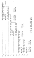
- Fig. 7 is a block diagram showing the construction of picture coding device applied a picture signal transmission method and a picture signal transmission device according to this invention;
- Fig. 8 is a block diagram showing the construction of a picture decoding device applied a picture signal transmission method and a picture signal transmission device according to this invention;
- Fig. 9 is a connection diagram showing the construction of intra field transform circuit;
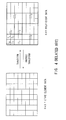
- Fig. 10 is a schematic diagram illustrating the intra field component separate coding and reconstruction of picture signal;
- Figs. 11A and 11B are schematic diagrams illustrating the construction method of low frequency coefficient block;
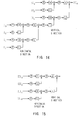
- Fig. 12 is a connection diagram showing the construction of intra frame transform circuit;
- Fig. 13 is a schematic diagram illustrating the intra frame component separation and reconstruction on low frequency coefficients;
- Fig. 14 is a connection diagram showing the construction of intra frame inverse transform circuit; and
- Fig. 15 is a connection diagram showing the construction of intra field inverse transform circuit.
- Preferred embodiments of this invention will be described with reference to the accompanying drawings.
- Figs. 7 and 8 show a picture coding device and a picture decoding device applied the picture signal transmission method and the picture signal transmission device according to this invention. In this case, component separate coding is Wavelet transform using Haar function and processed in each block of 8 picture elements x 4 lines in the field. In this picture coding device, input picture signal S21 is inputted firstly to the intra
field transform circuit 21. The intrafield transform circuit 21 is constructed by, as shown in Fig. 9, Wavelet transform circuit, and performs component separate coding, i.e., transform, for the first and second fields of picture signal S21 formed by 8 picture elements x 4 lines block in the field respectively as shown in Fig. 10 and the resultant coefficient S22 is outputted. - The each coefficient S22 of the first and the second field outputted from the intra
field transform circuit 21 is inputted to ashunt circuit 22 and coefficient S23 comprising three kinds of high frequency components III₁, III₂, and III₃ in the coefficient S22 is inputted to amultiplexing circuit 23, and the first field coefficient S24 in the coefficient of one type of low frequency component III₀, is stored once in thememory 24 which delays for time required for processing of second field and the second field coefficient S25 in the coefficient of one type of low frequency component III₀ is inputted to a low frequency coefficientblock construction circuit 25. - In the low frequency coefficient
block construction circuit 25, the low frequency coefficient block is constructed by the block construction method in utilizing the first field low frequency coefficient S26 and the second field low frequency coefficient S25 read out from thememory 24, as shown in Figs. 11A and 11B. In the case of this embodiment, which block construction method would be applied for constructing the low frequency coefficient block is determined by the block construction information S27 inputted from the blockconstruction determination circuit 26. - In this block
construction determination circuit 26, the similarity of coefficient values between the first field low frequency coefficient S26 and the second field low frequency coefficient S25 read out from thememory 24 is calculated and the block construction method which the electric power to center on the more low frequency coefficient is determined and the block construction information S27 is outputted according to the block construction method. - In practice, in the case where the block construction method shown in Fig. 11B is used in place of the block construction method shown in Fig. 11A, for example, if Haar function is used for separation and reconstruction, it becomes equivalent to the case where the separation in the vertical direction of the low frequency coefficient block constructed is performed once more in the field and it becomes very effective low frequency separation for the picture pattern of vigorously moving and having poor inter field correlation.
- Coefficient block data S28 corresponding to low frequency coefficient block constructed at the low frequency coefficient
block construction circuit 25 is inputted to an intraframe transform circuit 27. The intraframe transform circuit 27 is constructed by Wavelet transform circuit as shown in Fig. 12 for example, and performs component separate coding i.e., transform as shown in Fig. 13 on coefficient block data S28 corresponding to the low frequency coefficient block, and the resulting coefficient S29 is outputted to amultiplexing circuit 23. - The multiplexing
circuit 23 performs time division multiplex on the coefficient S23 of three kinds of high frequency components obtained upon intra field transformed and the coefficient S29 obtained upon low frequency coefficient block is transformed in the field, and the resultant coefficient S30 is outputted to aquantizer 28. In thequantizer 28, the coefficient S30 is quantized according to the accuracy of quantization to be determined by the quantization step size information S31 which is determined by the amount of storage of thebuffer memory 30, and becomes quantization coefficient S32. - The quantization coefficient S32 is inputted to a variable
length coding circuit 29 and is variable length coded combining Huffman coding and zero run-length coding as before, the resultant variable length coding quantization coefficient S33 is inputted to themultiplexer 31 after the amount of information is smoothed through thebuffer memory 30 for smoothing the generation information amount, and here it is multiplexed to block construction information S27 and quantization step size information S31 and is outputted as output data S34 of picture coding device. - On the other hand, in the picture decoding device, output data S34 of the picture coding device is inputted as input data S41 to the
shunt circuit 41 and is outputted upon being shunted to quantization step size information S42, block construction information S44, and quantization coefficient variable length coded S43. The variable length coded quantization coefficient S43 is inputted to thebuffer memory 42 and the output S43 of this buffer memory is inputted to a variablelength decoding circuit 43 and is variable length decoded to become quantization coefficient S45. - The quantization coefficient S45 becomes dequantization coefficient S46 being dequantized according to the quantization step size information S42 at a
dequantizer 44 and is inputted to ashunt circuit 45. At theshunt circuit 45 dequantization coefficient S46 is shunted to low frequency separate coefficient S47 and the high frequency separate coefficient S48. The low frequency separate coefficient S47 is inputted to intra frameinverse transform circuit 46, and the high frequency separate coefficient S48 is stored at amemory 47 once and is inputted to an intra field coefficientblock construction circuit 48 as data S49 delayed for the prescribed time. - The intra frame
inverse transform circuit 46 is constructed by Wavelet inverse transform circuit as shown in Fig. 14, and performs reconstruction, i.e., inverse transform, on the low frequency separate coefficient S47 as shown in Fig. 13, and inputs the resulting low frequency coefficient block data S50 to an intra fieldcoefficient construction circuit 48. - In the intra field coefficient
block construction circuit 48, the low frequency coefficient block data S50 is separated into the respective low frequency coefficient data of the first and second field based on the block construction information S44 inputted from theshunt circuit 41 and, in utilizing the low frequency coefficient data and the high frequency separate coefficient data S49 inputted from thememory 47, the first and second field intra-field coefficient data block is constructed and the data S51 is outputted to an intra fieldinverse transform circuit 49. - The intra field
inverse transform circuit 49 is constructed by Wavelet inverse transform circuit as shown in Fig. 15, and performs reconstruction, i.e., inverse transform, as shown in Fig. 10 for respective intra field coefficient blocks of the first and second fields, and thus, the picture signal is restored and outputted as output picture signal S52 of the picture decoding device. - With this arrangement, the high frequency component separate coding is performed in the field and the low frequency component separate coding is performed in the frame, and by improving the capacity for picture patterns contained in the slow movement the visible distortion on the slowly moving restored picture is improved and thus improving the visual picture quality the transmission of high picture quality picture signal can be performed.
- Furthermore, since it becomes possible to perform easily the simple decoding using only low frequency coefficients with the simple device, high velocity simple reproduction, etc. in the video tape recorder or disc device can be realized easily. Moreover, by pluralizing the separating format of low frequency to be performed in the frame and shifting and using a plurality of format, the coding efficiency change by the movement amount of input picture signal is suppressed and simultaneously, overall coding efficiency can be further improved and the transmission of higher picture quality picture signal can be performed.
- According to the construction descried above, in the first and second fields of picture signal, component separate coding is performed in each field respectively, and by preventing the effect by the movement between fields, the declining of compressibility by the movement is avoided, and furthermore, a new block is constructed by the resultant low frequency component of the two fields and further component separate coding in the frame, the low frequency components which are not easily affected by the slow movement can be efficiently coded, and as a result, the picture signal transmission method and picture signal transmission device which are capable of increasing the compressibility for the picture containing the slow movement can be obtained.
- According to the construction described above, by performing the reconstruction on the block comprising low frequency components of two fields which are intra frame component separate coded, the simple decoding to restore frame picture easily can be performed, and furthermore, since the separation format of low frequency to be performed in the frame is so arranged that the electric power to center at the low frequency coefficient in accordance with the similarity of coefficient value of low frequency components of two field, the picture signal transmission method and picture signal transmission device capable of improving further the efficiency of coding can be obtained.
- Moreover, the embodiment discussed above has dealt with the case of performing the component separate coding of picture signal in each field using Haar function in every block of 8 picture elements x 4 lines. However, the block size is not only limited to the above, but also various sizes, e.g., 8 picture elements x 8 lines, may be selected. In this connection in case of performing component separate coding in every block of 8 picture elements x 8 lines, the construction of low frequency coefficient block may be selected from various construction methods accordingly, the same effects as those of the embodiment discussed above can be obtained.
- Furthermore, the embodiment described above has dealt with the case of component separate coding of picture signal by Wavelet transform using Haar function. However, the transform method is not only limited to the above, but is also widely applicable, such as to the sub-band coding which divides picture signal to multiple components and coding.
- In addition, the embodiment described above has dealt with the case of variable length coding only the quantization coefficient. However, this invention is not limited to this, but is also capable of variable length coding the quantization coefficient and the block construction information. In this case, the block construction information is coded/decoded through the route indicated by broken lines in Figs. 7 and 8.
- According to the embodiments of the present invention as described above, in the case where the picture signal in which one frame is constructed by two fields is component separate coded and picture information is compressed and transmitted, the component separate coding of high frequency is performed in the field and the component separate coding of low frequency is performed in the frame, and by improving the capacity for picture pattern containing slow movement, visible distortion of a slowly moving decoded picture can be improved and picture signal transmission capable of improving the visual picture quality and transmitting high quality picture signals can be obtained.
- While there have been described the preferred embodiments of the invention, it will be clear to those skilled in the art that various changes and modifications may be made.
Claims (10)
- A picture signal coding method for coding a picture signal of one frame consisting of a first and a second fields, comprising the steps of:
component separating said first and said second fields for each field, and generating the coefficients of the first and the second fields;
quantizing high frequency coefficients in the coefficients of said first and said second fields, and generating first quantization coefficients;
composing coefficient blocks combining low frequency coefficients in the coefficients of said first and said second fields;
component separating said coefficient blocks;
quantizing said coefficient blocks component separated, and generating second quantization coefficients; and
coding said first and said second quantization coefficients. - The picture signal coding method according to claim 1, comprising the steps of:
changing the construction of said coefficient blocks based on the similarities between the low frequency coefficients of said first field and the low frequency coefficients of said second field; and
coding the information representing said coefficient blocks. - The picture signal coding method according to claim 2, wherein when said similarities are high, the low frequency of said first field and the low frequency of said second field are arranged to interlace so as to compose said coefficient blocks, and when said similarities are low, the low frequency of said first field and the low frequency of said second field are separated respectively to compose said coefficient blocks.
- A picture signal decoding method for decoding a picture signal component separate coded, comprising the steps of:
dequantizing low frequency quantization coefficients consisting of quantization coefficients in accordance with the low frequency components of a first and a second fields, and generating low frequency separate coefficients;
inverse transforming said low frequency separate coefficients and generating low frequency coefficient blocks;
respectively dequantizing quantization coefficients in accordance with the high frequency components of said first and said second fields, and generating the respective high frequency separate coefficients of said first and said second fields;
composing the coefficient blocks of said first and said second field based on said low frequency coefficient blocks and said high frequency separate coefficients; and
respectively inverse transforming the coefficient blocks of said first and said second fields in the field, and restoring the picture signals of said first and said second fields. - The picture signal decoding method according to claim 4, comprising the steps of:
separating the information representing the construction of said low frequency coefficient blocks from the transmitted coding signal; and
dividing said low frequency coefficient blocks into the coefficient blocks of said first field and the coefficient blocks of said second field based on the information representing the construction of said low frequency coefficient blocks. - A picture signal coding device for coding a picture signal of one frame consisting of a first and a second fields, comprising:
an intra-field transform means for separating said first and said second fields for each field, and generating the coefficients of the first and the second fields;
a quantization means for quantizing high frequency coefficients in the coefficients of said first and said second fields, and generating first quantization coefficients;
a blocking means for composing coefficient blocks combining low frequency coefficients in the coefficients of said first and said second fields;
an intra-frame transform means for component separating said coefficient blocks;
a quantization means for quantizing said coefficient blocks component separated, and generating second quantization coefficients; and
a cording means for coding said first and said second quantization coefficients. - The picture signal coding method according to claim 6, wherein;
said blocking means changes the construction of said coefficient blocks based on the similarities between the low frequency coefficients of said first field and the low frequency coefficients of said second field, and
the picture signal cording device further comprises a coding means for coding the information representing said coefficient blocks. - The picture signal coding device according to claim 7, wherein when said similarities are high, said blocking means arranges the low frequency of said first field and the low frequency of said second field to interlace so as to compose said coefficient blocks, when said similarities are high, and said blocking means arranges the low frequency of said first field and the low frequency of said second field to separate respectively so as to compose said coefficient blocks, when said similarity are low.
- A picture signal decoding device for decoding a picture signal component separate coded, comprising:
a dequantization means for dequantizing the low frequency quantization coefficients consisting of quantization coefficients in accordance with the low frequency components of a first and a second fields, and generating low frequency separate coefficients;
an intra-frame inverse transform means for inverse transforming said low frequency separate coefficients and generating low frequency coefficient blocks;
a dequantization means for respectively dequantizing quantization coefficients in accordance with the high frequency components of said first and said second fields, and generating the respective high frequency separate coefficients of said first and said second fields;
a blocking means for composing the coefficient blocks of said first and said second field based on said low frequency coefficient blocks and said high frequency separate coefficients; and
an intra-field inverse transform means for respectively inverse transforming the coefficient blocks of said first and said second fields in the field, and restoring the picture signals of said first and said second fields. - The picture signal decoding device according to claim 9, comprising a means for separating the information representing the construction of said low frequency coefficient blocks from the transmitted coding signal, and
said blocking means divides said low frequency coefficient blocks into the coefficient blocks of said first field and the coefficient blocks of said second field based on the information representing the construction of said low frequency coefficient blocks.
Applications Claiming Priority (2)
| Application Number | Priority Date | Filing Date | Title |
|---|---|---|---|
| JP121929/93 | 1993-04-26 | ||
| JP12192993A JPH06311496A (en) | 1993-04-26 | 1993-04-26 | Method and device for transmitting picture signal |
Publications (2)
| Publication Number | Publication Date |
|---|---|
| EP0622961A2 true EP0622961A2 (en) | 1994-11-02 |
| EP0622961A3 EP0622961A3 (en) | 1995-02-22 |
Family
ID=14823427
Family Applications (1)
| Application Number | Title | Priority Date | Filing Date |
|---|---|---|---|
| EP19940302917 Withdrawn EP0622961A3 (en) | 1993-04-26 | 1994-04-25 | Picture signal coding/decoding methods and devices. |
Country Status (3)
| Country | Link |
|---|---|
| US (1) | US5541659A (en) |
| EP (1) | EP0622961A3 (en) |
| JP (1) | JPH06311496A (en) |
Cited By (7)
| Publication number | Priority date | Publication date | Assignee | Title |
|---|---|---|---|---|
| WO1999059329A2 (en) * | 1998-05-14 | 1999-11-18 | Interval Research Corporation | Video compression with storage reduction, color rotation, combined signal and border filtering |
| EP0987882A2 (en) * | 1998-09-18 | 2000-03-22 | Techno Link Co., Ltd. | Interlace noise filter |
| US6229929B1 (en) | 1998-05-14 | 2001-05-08 | Interval Research Corporation | Border filtering of video signal blocks |
| US6396948B1 (en) | 1998-05-14 | 2002-05-28 | Interval Research Corporation | Color rotation integrated with compression of video signal |
| US6516030B1 (en) | 1998-05-14 | 2003-02-04 | Interval Research Corporation | Compression of combined black/white and color video signal |
| US7130351B1 (en) | 1998-05-14 | 2006-10-31 | Vulcan Patents Llc | Storage reduction during compression |
| US8116377B2 (en) | 1998-11-20 | 2012-02-14 | Interval Licensing Llc | Low cost video compression using fast, modified Z-coding of wavelet pyramids |
Families Citing this family (11)
| Publication number | Priority date | Publication date | Assignee | Title |
|---|---|---|---|---|
| US6266374B1 (en) | 1994-10-28 | 2001-07-24 | Lg Electronics Inc. | Low level digital video decoder for HDTV having backward compatibility |
| JPH08186815A (en) * | 1994-12-28 | 1996-07-16 | Pioneer Electron Corp | Sub band coding method |
| JP3534465B2 (en) * | 1994-12-28 | 2004-06-07 | パイオニア株式会社 | Subband coding method |
| KR0159434B1 (en) * | 1995-04-19 | 1999-01-15 | 김광호 | Wavelet image encoding and decoding device and method using human visual system modeling |
| US5845015A (en) * | 1995-10-12 | 1998-12-01 | Sarnoff Corporation | Method and apparatus for resizing images using the discrete cosine transform |
| IL117133A (en) * | 1996-02-14 | 1999-07-14 | Olivr Corp Ltd | Method and system for providing on-line virtual reality movies |
| US20020044692A1 (en) * | 2000-10-25 | 2002-04-18 | Goertzen Kenbe D. | Apparatus and method for optimized compression of interlaced motion images |
| US20030185455A1 (en) * | 1999-02-04 | 2003-10-02 | Goertzen Kenbe D. | Digital image processor |
| US20030142875A1 (en) * | 1999-02-04 | 2003-07-31 | Goertzen Kenbe D. | Quality priority |
| ES2253486T3 (en) * | 2002-10-30 | 2006-06-01 | Visiowave S.A. | METHOD OF CALCULATING COEFFICIENTS OF SMALL TEMPORARY WAVES ("WAWELETS") OF A GROUP OF IMAGES. |
| CN103152573A (en) * | 2013-03-15 | 2013-06-12 | 惠州Tcl移动通信有限公司 | Method and system for transmitting image frame between mobile terminal and intelligent television set |
Citations (4)
| Publication number | Priority date | Publication date | Assignee | Title |
|---|---|---|---|---|
| EP0502545A2 (en) * | 1991-03-07 | 1992-09-09 | Mitsubishi Denki Kabushiki Kaisha | Encoding apparatus for encoding a digital image signal |
| WO1992022166A1 (en) * | 1991-06-04 | 1992-12-10 | Qualcomm Incorporated | Adaptive block size image compression method and system |
| US5235420A (en) * | 1991-03-22 | 1993-08-10 | Bell Communications Research, Inc. | Multilayer universal video coder |
| EP0588476A2 (en) * | 1992-09-17 | 1994-03-23 | Sony United Kingdom Limited | Video data compression |
Family Cites Families (7)
| Publication number | Priority date | Publication date | Assignee | Title |
|---|---|---|---|---|
| GB8603880D0 (en) * | 1986-02-17 | 1986-03-26 | Indep Broadcasting Authority | Hybrid interpolative predictive code |
| EP0339589A3 (en) * | 1988-04-28 | 1992-01-02 | Sharp Kabushiki Kaisha | Orthogonal transform coding system for image data |
| ES2093649T3 (en) * | 1990-02-06 | 1997-01-01 | Alcatel Italia | SYSTEM, PACKAGE STRUCTURE AND DEVICE TO PROCESS THE INFORMATION PROVIDED BY A SIGNAL ENCODER. |
| US5189526A (en) * | 1990-09-21 | 1993-02-23 | Eastman Kodak Company | Method and apparatus for performing image compression using discrete cosine transform |
| US5268755A (en) * | 1991-02-21 | 1993-12-07 | Matsushita Electric Industrial Co., Ltd. | Orthogonal transformation encoder |
| US5351083A (en) * | 1991-10-17 | 1994-09-27 | Sony Corporation | Picture encoding and/or decoding system |
| KR100255528B1 (en) * | 1991-10-31 | 2000-05-01 | 요트.게.아. 롤페즈 | Television system for transmitting digitized television pictures from a transmitter to a receiver |
-
1993
- 1993-04-26 JP JP12192993A patent/JPH06311496A/en active Pending
-
1994
- 1994-04-25 EP EP19940302917 patent/EP0622961A3/en not_active Withdrawn
- 1994-04-25 US US08/232,995 patent/US5541659A/en not_active Expired - Fee Related
Patent Citations (4)
| Publication number | Priority date | Publication date | Assignee | Title |
|---|---|---|---|---|
| EP0502545A2 (en) * | 1991-03-07 | 1992-09-09 | Mitsubishi Denki Kabushiki Kaisha | Encoding apparatus for encoding a digital image signal |
| US5235420A (en) * | 1991-03-22 | 1993-08-10 | Bell Communications Research, Inc. | Multilayer universal video coder |
| WO1992022166A1 (en) * | 1991-06-04 | 1992-12-10 | Qualcomm Incorporated | Adaptive block size image compression method and system |
| EP0588476A2 (en) * | 1992-09-17 | 1994-03-23 | Sony United Kingdom Limited | Video data compression |
Cited By (10)
| Publication number | Priority date | Publication date | Assignee | Title |
|---|---|---|---|---|
| WO1999059329A2 (en) * | 1998-05-14 | 1999-11-18 | Interval Research Corporation | Video compression with storage reduction, color rotation, combined signal and border filtering |
| WO1999059329A3 (en) * | 1998-05-14 | 2000-02-03 | Interval Research Corp | Video compression with storage reduction, color rotation, combined signal and border filtering |
| US6229929B1 (en) | 1998-05-14 | 2001-05-08 | Interval Research Corporation | Border filtering of video signal blocks |
| US6396948B1 (en) | 1998-05-14 | 2002-05-28 | Interval Research Corporation | Color rotation integrated with compression of video signal |
| US6516030B1 (en) | 1998-05-14 | 2003-02-04 | Interval Research Corporation | Compression of combined black/white and color video signal |
| AU768853B2 (en) * | 1998-05-14 | 2004-01-08 | Interval Research Corporation | Video compression with storage reduction, color rotation, combined signal and border filtering |
| US7130351B1 (en) | 1998-05-14 | 2006-10-31 | Vulcan Patents Llc | Storage reduction during compression |
| EP0987882A2 (en) * | 1998-09-18 | 2000-03-22 | Techno Link Co., Ltd. | Interlace noise filter |
| EP0987882A3 (en) * | 1998-09-18 | 2003-05-28 | Techno Link Co., Ltd. | Interlace noise filter |
| US8116377B2 (en) | 1998-11-20 | 2012-02-14 | Interval Licensing Llc | Low cost video compression using fast, modified Z-coding of wavelet pyramids |
Also Published As
| Publication number | Publication date |
|---|---|
| JPH06311496A (en) | 1994-11-04 |
| EP0622961A3 (en) | 1995-02-22 |
| US5541659A (en) | 1996-07-30 |
Similar Documents
| Publication | Publication Date | Title |
|---|---|---|
| US5541659A (en) | Picture signal coding/decoding method and device using thereof | |
| US5301032A (en) | Digital image compression and decompression method and apparatus using variable-length coding | |
| KR100289587B1 (en) | An image signal encoding method and an image signal encoding apparatus, an image signal decoding method and an image signal decoding apparatus, and an image signal recording medium | |
| US5173773A (en) | Moving picture signal progressive coding system | |
| US5126842A (en) | Video signal encoding method with a substantially constant amount of transform data per transmission unit block | |
| USRE44091E1 (en) | Picture encoding method, picture encoding apparatus and picture recording medium | |
| JP3085024B2 (en) | Image recompressor and image recording device | |
| US5253075A (en) | Image signal coding/decoding system using adaptive quantization | |
| EP0596423A2 (en) | Layer encoding/decoding apparatus for input non-interlace video signal | |
| US6249610B1 (en) | Apparatus and method for coding a picture and apparatus and method for decoding a picture | |
| EP0782342A2 (en) | Video coding and decoding system and method | |
| JPH0583696A (en) | Picture encoding device | |
| JPH07123447A (en) | Method and device for recording image signal, method and device for reproducing image signal, method and device for encoding image signal, method and device for decoding image signal and image signal recording medium | |
| JPH09182084A (en) | Moving image encoding and decoding device | |
| JPH11262018A (en) | Motion compensation coder, motion compensation coding method and motion compensation recording medium therefor | |
| US5905846A (en) | Image decoding apparatus and process thereof and image reproduction apparatus | |
| US5291283A (en) | Decoding apparatus of a compressed digital video signal | |
| JPH09182085A (en) | Image encoding device, image decoding device, image encoding method, image decoding method, image transmitting method and recording medium | |
| JP2890740B2 (en) | Digital video signal playback device | |
| KR100468384B1 (en) | Moving object based Motion estimation Wavelet picture Compression and Decompression system | |
| JP3129075B2 (en) | Image data compression method | |
| JPH05130592A (en) | Moving picture encoding device | |
| EP0927954B1 (en) | Image signal compression coding method and apparatus | |
| JPH0549021A (en) | High efficient coder | |
| KR0160621B1 (en) | Method and device for image compression and decompression |
Legal Events
| Date | Code | Title | Description |
|---|---|---|---|
| PUAI | Public reference made under article 153(3) epc to a published international application that has entered the european phase |
Free format text: ORIGINAL CODE: 0009012 |
|
| AK | Designated contracting states |
Kind code of ref document: A2 Designated state(s): DE FR GB |
|
| PUAL | Search report despatched |
Free format text: ORIGINAL CODE: 0009013 |
|
| AK | Designated contracting states |
Kind code of ref document: A3 Designated state(s): DE FR GB |
|
| 17P | Request for examination filed |
Effective date: 19950629 |
|
| 17Q | First examination report despatched |
Effective date: 19961014 |
|
| RIC1 | Information provided on ipc code assigned before grant |
Free format text: 7H 04N 7/26 A, 7H 04N 7/54 B |
|
| STAA | Information on the status of an ep patent application or granted ep patent |
Free format text: STATUS: THE APPLICATION IS DEEMED TO BE WITHDRAWN |
|
| 18D | Application deemed to be withdrawn |
Effective date: 20020919 |