EP0621661B1 - Socket for electrical installation - Google Patents
Socket for electrical installation Download PDFInfo
- Publication number
- EP0621661B1 EP0621661B1 EP94100832A EP94100832A EP0621661B1 EP 0621661 B1 EP0621661 B1 EP 0621661B1 EP 94100832 A EP94100832 A EP 94100832A EP 94100832 A EP94100832 A EP 94100832A EP 0621661 B1 EP0621661 B1 EP 0621661B1
- Authority
- EP
- European Patent Office
- Prior art keywords
- socket according
- housing
- contact
- groove
- idc
- Prior art date
- Legal status (The legal status is an assumption and is not a legal conclusion. Google has not performed a legal analysis and makes no representation as to the accuracy of the status listed.)
- Expired - Lifetime
Links
Images


Classifications
-
- H—ELECTRICITY
- H01—ELECTRIC ELEMENTS
- H01R—ELECTRICALLY-CONDUCTIVE CONNECTIONS; STRUCTURAL ASSOCIATIONS OF A PLURALITY OF MUTUALLY-INSULATED ELECTRICAL CONNECTING ELEMENTS; COUPLING DEVICES; CURRENT COLLECTORS
- H01R33/00—Coupling devices specially adapted for supporting apparatus and having one part acting as a holder providing support and electrical connection via a counterpart which is structurally associated with the apparatus, e.g. lamp holders; Separate parts thereof
- H01R33/05—Two-pole devices
- H01R33/06—Two-pole devices with two current-carrying pins, blades or analogous contacts, having their axes parallel to each other
- H01R33/065—Two-pole devices with two current-carrying pins, blades or analogous contacts, having their axes parallel to each other for supporting starter switches
-
- H—ELECTRICITY
- H01—ELECTRIC ELEMENTS
- H01R—ELECTRICALLY-CONDUCTIVE CONNECTIONS; STRUCTURAL ASSOCIATIONS OF A PLURALITY OF MUTUALLY-INSULATED ELECTRICAL CONNECTING ELEMENTS; COUPLING DEVICES; CURRENT COLLECTORS
- H01R4/00—Electrically-conductive connections between two or more conductive members in direct contact, i.e. touching one another; Means for effecting or maintaining such contact; Electrically-conductive connections having two or more spaced connecting locations for conductors and using contact members penetrating insulation
- H01R4/24—Connections using contact members penetrating or cutting insulation or cable strands
- H01R4/2416—Connections using contact members penetrating or cutting insulation or cable strands the contact members having insulation-cutting edges, e.g. of tuning fork type
- H01R4/242—Connections using contact members penetrating or cutting insulation or cable strands the contact members having insulation-cutting edges, e.g. of tuning fork type the contact members being plates having a single slot
- H01R4/2425—Flat plates, e.g. multi-layered flat plates
- H01R4/2429—Flat plates, e.g. multi-layered flat plates mounted in an insulating base
Definitions
- the electrical connection between the external wiring and one of the two contact spring tongues happens via self-clamping contacts by going through from the outside a corresponding opening in the housing the stripped Wire end is inserted.
- the contact spring tongue contains an additional punched-out area in the area of the opening Tongue and one following the Tongue angled contact area as abutment for the inserted wire end that is between this Area and the free end of the spring tongue becomes.
- the entire arrangement from the contact tongue for the socket pins and the contact tongue for the conductor connection is made from a sheet metal strip, which corresponds essentially over its flat side is bent.
- connection between the external wiring and the starter has its own spring tongue, which housed in the other part of the case is.
- DE-A-4108390 discloses a socket for a vehicle lamp, wherein Insulation displacement devices for cables are provided.
- the object of the invention is one to use to create a version adapted by insulation displacement contacts, whose individual parts are easy to manufacture and light are to be assembled into the finished version.
- An advantageous embodiment of the invention Version has the following features.
- the Width of the groove-like depressions which is an accidental Prevent touching of live parts, larger than the outside diameter of the pipe.
- the groove-like recess is deeper than the insertion slot, to ensure in any case that with the required conductor cross section and required wall thickness of the plastic insulation Conductor actually as far as possible into the insulation displacement slot can be introduced.
- the new version can be used both for fluorescent lamps and also for incandescent lamps as well as for receiving starters used when in their outer form is adjusted accordingly.
- the casing of the socket two is approximately rectangular has mutually extending legs, of which which contains the opening for the socket pins, while in the other leg the chambers with the Insulation displacement contacts are housed.
- the groove-like depressions in addition to the respective insulation displacement contacts form two grooves that are parallel and spaced apart and by far the front of the first Thighs run. This makes it possible to use the Assembly tool or the wire unhindered to be able to drive past the front of the socket. A Collision of the tool with the front is not to fear.
- the start detection device advantageously in a lateral extension of the first leg. That’s it possible the contact spring assembly from the second Thigh by bending over the flat side in those Bring area where starter is used whose socket pins are.
- the housing has expedient the shape of a cuboid, the chambers for the insulation displacement contacts in the area of a the sides of the cuboid.
- the contact spring arrangement expediently a stamped sheet metal part, it can around an axis be bent perpendicular to the flat side if one Target bending point is provided.
- This arrangement will expediently used in socket housings where a corresponding floor area over a film hinge is attached in one piece to the first housing leg.
- the contact spring arrangement can with such a housing in the stretched state in corresponding support members or structures are inserted, and the desired angled shape, that of the assembly wiring accommodates, is by folding up the concerned Floor area achieved.
- Fig. 1 shows a socket 1 for socketed at both ends Fluorescent lamps with two socket pins.
- Version 1 contains a housing 2 made of insulating material, which, in side view seen, is approximately L-shaped. It consists of an upstanding first housing leg 3 and one lying second housing leg 4, the longitudinal axes intersect at right angles. The two housing legs 3 and 4 go into one another in an angular range 5 about. They each have one for themselves in the broadest Sense cuboid shape.
- the first housing leg 3 is from one of the second housing legs 4 facing front wall 6 limited to one side wall arrangement 7 is formed in one piece.
- This side wall arrangement 7 forms one of the outer contour the front wall 6 largely following the collar raised to the rear.
- On the back is a too the cover 8 belonging to the first housing leg 3 is fitted.
- This lid 8 ends at a lower edge 9, which is higher than the top of the second housing leg 4 corresponds. It is about where the first housing leg 3 two symmetrically arranged Has recesses 11 on which the first housing leg 3 tapered in width. in the Connection to the two recesses 11 is the first Housing leg 3 in two parallel to each other Side walls 12 over.
- the front wall 6 contains a cylindrical in a known manner Bore 13 into which the side wall arrangement also from above 7 penetrating slot 14 opens.
- a T-shaped in cross section Rotating body 15 rotatably mounted, which serves with the lamp removed, electrically conductive parts inside to close version 1 inaccessible.
- the second housing leg 4 consists essentially of one flat bottom plate 16, which at its the first Housing leg 3 adjacent end over the two in parallel spaced side walls 12 is connected to the first housing leg 3. Laterally next to the two side walls 12 are from the bottom plate 16 two towards the first housing leg 3 pointing arms 17 divided on her free end carry a foot 18 pointing downwards.
- the feet 18 are opposite to the first Housing leg 3 remote side of the base plate 16 at a distance from each other two locking feet 19 are integrally formed. The feet 18 and the locking feet 19 point into the same direction, namely away from the base plate 16.
- the bottom plate 16 From the top facing the first housing leg 3 the bottom plate 16 rise a total of three Walls 21, 22, 23 that are parallel and spaced apart run and also parallel to one through the front 6 defined level. These three walls 21, 22 and 23 delimit two parallel to one another Grooves 24 and 25. Their top edges 26 are each flat and are at the same height, the upper edge 26 the wall 23 merges into a roof wall 27, which is in one piece is integrally formed on the front wall 6.
- the side walls 12 also go below the roof wall 27 in one piece in the wall 23 and in the underside of the roof wall 27 about. Finally run between the two Side walls 12 still two partitions 28, which also, like the side walls 12, are approximately L-shaped and both on the back of the front wall 8, to the bottom of the Roof wall 27, the back of wall 23 and the top the bottom plate 16 are integrally formed. Your trailing edge 29 jumps against a rear edge 31 of the side walls 12 slightly back, the rear edges 31 with the free edge of the side wall assembly 7 are flush.
- the groove 24, the wall 21 is not over the entire Width of the bottom plate 16 extends approximately in their Middle through a chamber 33 in two about the same length groove-like depressions 34 and 35 divided, each groove-like recess 34, 35 of two parallel to each other extending straight groove walls 36 and 37 and one groove bottom 32 extending at right angles thereto that is also the top of the base plate 16 is.
- the chamber 33 is parallel and spaced from two chamber walls running at right angles to the groove walls 36, 37 38 limited, which mirror each other are.
- each of the Top edge 26 to the top of the bottom plate 16 are sufficient, are aligned insertion slots 39 included, which are in the middle of the concerned Groove 24 are located and at 41 clearly above the base plate 16 ends.
- the insertion slots 39 in the two Chamber walls 38 widen at their upper end funnel-shaped at 43.
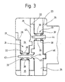
- Chamber 33 has, in particular 3 shows, in the clearance profile the groove 24 has a somewhat larger width, measured in the longitudinal direction the groove 24 as in one to the left of the groove 24 lying chamber section 43.
- This chamber section 43 is also limited in parallel and extends up to down to the top of the bottom plate 16.
- slit 44 is in the direction of the groove 25 with a funnel-shaped Extension 45 provided and contains within the Wall 26 one from the top edge 26 to the top the base plate 16 extending extension.
- the slot 44 is symmetrical with respect to one Chamber section 43 symmetrically penetrating and on the bottom plate 16 vertical plane. Likewise is symmetrical about this plane in one Recess 46 in the wall 23 a rectangular, on all sides delimited opening 47.
- the width of the opening 47 corresponds the clear width of the slot 44, while the height is significantly less than the height of the remaining walls 21, 22 and 23 of the same height opening 47 goes smoothly into the top at the lower end the bottom plate 16 over.
- Finally the opening lies 47 symmetrically between the partition 28 and each adjacent sidewall 12. The distance that the Sidewall 12 of the partition 28 is larger than it corresponds to the width of the opening 47.
- Chamber 48 is present in the groove 25, and the chamber 48 is in the longitudinal direction of the groove 25 the chamber 33 offset.
- Chamber 48 is in similarly bounded by two chamber walls 38 which are designed in the same way as the chamber walls 38 of the chamber 33 and therefore the same reference numerals are used. They too are made by one Insertion slot 39 partially penetrated.
- chamber 48 has a chamber section 43 on, but in this case lies in the wall 46.
- the socket 1 contains two largely identical contact spring arrangements 49.
- the shown Contact spring assembly 49 is for use in the chamber 33 determined. It has a spring tongue 51, a connector 52 and an insulation displacement contact 53, which are all connected to one another in one piece.
- the insulation displacement contact 53 has the shape of a rectangular one Plate with a height of approx. 8 mm and one Thickness from about 0.3 to 0.5 mm. He is joined by two parallel edges 54 and 55 laterally and above and bounded below by two edges 56 and 57. The edge 57 is straight and parallel to edge 56. From the latter goes out an insulation displacement slot 58, which is parallel to edges 54 and 55 towards the lower edge 57 extends.
- the height of the insulation displacement contact 53, measured between the lower edge 57 and the upper edge 56, is slightly smaller than the height of the opening 47. Das against it has the lower end of the insulation displacement slot 58 from the lower edge 57 a smaller distance than the lower end 41 of the insertion slot 39 from the Top of the bottom plate 16.
- the connector 52 that the insulation displacement contact 53rd connects in one piece with the contact spring tongue 51 approximately L-shaped and consists of a lower leg 61, the lower edge of which merges flush with the lower edge 57 and an upper leg 62 that is rectangular is arranged to the leg 61.
- Between the two Legs 61 and 62 is approximately 45 ° Section 63 inserted, one of which is in the gusset area projecting between the legs 61 and 62 Extension 64 runs out.
- the height of the leg 61 is so dimensioned that it is significantly smaller than the distance of the lower end 41 of the insertion slot 39 from the Top of the bottom plate 16.
- the intermediate piece 63 has minus the extension 64 about the same thickness as the leg 61 and also the leg 62, which finally rises up at right angles and in the same Level lies like the insulation displacement contact 53, has one Thickness corresponding to leg 61.
- the adjoining the upper end of the leg 62 Contact spring tongue 51 is in the middle at 65 slightly V-shaped and its width is close to that Adjusted the length of the socket pins to be contacted, i.e. their width corresponds approximately to the clear width between the back of the front wall 6 and the inside of the rear cover 8.
- the contact spring tongue 51 goes in at its upper end a tab 66 with which the contact spring tongue 51st between corresponding ribs in the first housing leg 3 is held in a known manner.
- the extension 64 has an upper and a front edge 67 and 68 limits, the exact dimensions of which differ the following assembly description.
- the front edge 54 of the Insulation displacement contact 53 is low Distance from the opposite wall of the ventricular process 43. At the same time in this position lies in one level leading edge of the contact spring tongue 51 and the front edge extending therewith in extension of leg 62 on the back of the front wall 6 on. The upper edge 67 of the extension 64 against it lies with little play below the bottom of the Roof wall 27. The tab 66 is finally between corresponding Ribs tied up in the housing leg 3.
- the leg 61 leads of the connecting piece 52 lying bare through the groove 25 through. However, this happens in one Distance from the top edges 26 of the two walls 22 and 23 that contact is excluded. Also is through the section extending through the groove 25 of the leg 61 does not isolate one over it leading wire at risk because the top of the Leg 61 is significantly lower than the lower End of insertion slot 39.
- the invisible contact spring assembly 49 for the chamber 48 has, aside from the length of the leg 61, like already mentioned, the same shape as the contact spring arrangement shown 49.
- the length of the leg is 61 dimensioned so that when inserting this contact spring assembly into the other, invisible opening 47 of the Insulation displacement contact 53, as previously mentioned, in the chamber 48 comes to rest when the front edge 68 of the extension 64 and the front edge of the contact spring tongue 65 on the one hand on the back of the wall 23 and on the other hand Bump on the back of the front wall 6.
- both contact spring assemblies 49 slides these with their lower edge 57 free and without any Projections to be hindered on the top the base plate 16 into the associated chamber 33 or 48.
- Both contact spring assemblies 49 are in the assembled Condition with its lower edge 57 flat on the top the base plate 16, with the respective insulation displacement slot 58 centered in the insertion slot 39 of the stands two chamber walls 38. The lower end of the insulation displacement slot 58 disappears under the respective Chamber wall 38.
- the back cover 8 is the lower part of the first housing leg 3 and also the ones that follow Area of the second housing leg 4 is not covered and thus part of the leg 62 and the intermediate piece 63 lies bare, there is still no danger because the side walls 12 in connection with the two Partitions 28 ensure protection against contact.
- the rear edge of the leg 62 or the intermediate piece 63 jump opposite the trailing edges 29 or 31 so far back that at the given distance between the partition wall 28 and the adjacent side wall 12 the usual for checking the touch safety Ball does not reach the contact spring assembly 49 can.
- the new version is wired in such a way that with the help of a tool a non-stripped Head of suitable cross-section and outside diameter is pressed into the respective chamber 33 from above.
- the insulation displacement contact 53 cuts the insulation by the rest between the edges of the insertion slot 39 is only jammed.
- Assembly force is applied directly to the base plate 16 transfer. There are no forces that would strive the contact spring assembly 49 contrary to that mentioned above Insertion movement when mounting the socket 1 eject from the housing again. This result will be achieved in that the insulation displacement slot 38, the determines the direction of force when contacting, at right angles extends to the mounting direction in which the contact spring assembly 49 is inserted into the housing 2.
- the new solution can also are used for frames that are in a side Arm 71 a socket device 72 for a lamp starter exhibit.
- 4 has the second housing leg 4 the same shape as in the Embodiment according to FIGS. 1 to 3.
- the first housing leg 3 differs from the aforementioned embodiment only in that the side wall assembly 7 to form the mounting device 42 laterally is fully booked. Otherwise there is no difference.
- the version of FIG. 4 contains the Contact spring arrangement 49 according to FIG. 2.
- the starter pin shows a top view in FIG. 5.
- the base plate 16 can thus be seen in FIG. 5, the two protruding parallel at a distance from each other Side walls 12, the partition walls arranged between them 28 and between each pair of a partition 28 and a side wall 12 located rectangular Openings 47.
- the contact spring assembly 73 differs from the second contact spring arrangement of the embodiment 2 in that the leg 62 just above the return 11 is turned to the right and thence as a straight tongue 74 to one of the two keyhole-like Openings 75 for the starter base pins leads.
- the tongue 74 runs just through the clearance profile the lower opening 75 and is through in the molded part 71 of the rear of the front wall 6 Last held 76.
- the tongue 74 lies over their entire length on the front wall 6 from the rear on.
- the second electrical connection between the one to be used Lamp and the starter happens through a Contact spring tongue 77, which is similar to the contact spring tongue 51 over the bore 13 extending portion 78 has that above the bore 13 after turns right into a straight section 79.
- this contact spring 77 are on the periphery the bore 13 corresponding ribs 81 provided between which section 78 passes through. His lower The end is in a pocket 82.
- the straight section 79 leads from the ribs 81 to a bend 83 and from there again as one another straight section 84 just through the clearance profile the upper opening 75.
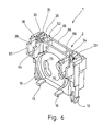
- FIG. 6 to 9 show a socket 1 which is provided for this purpose is a starter within a luminaire housing or other electrical equipment to hold corresponding socket pins. Also in this Traps are used for components made with components from the Fig. 1 to 3 or 5 and 6 are functionally the same Reference numerals used to indicate the homology between to recognize the components better.
- the version 1 according to FIGS. 6 to 9 consists of a one-piece housing 2, which has a front wall 87 as well has a rear wall 88 that extends between them Crosspieces 89 and side walls 90 are connected to one another are such that between the front and the Rear wall 87, 88 a sufficiently large space arises.
- the space is dimensioned so that if a starter with his socket pins through the keyhole shaped Openings 75 are inserted in the front wall 87 the free ends of the socket pins will not Bump on the inside of the rear wall 88.
- the two chambers 33 for two galvanically isolated insulation displacement contacts 58 provided.
- the two chambers 33 are exact mirror-symmetrical, so that the following description applies mutatis mutandis to both chambers 33.
- the one chamber wall 38 is from the Front wall 87 formed while the other rear Chamber wall 38 a cranked in the direction of the front wall 87 Area 88 is. Close both chamber walls 38 forward and backward collars 93 which the groove-shaped depressions 34 and 35 on both sides of the limit each chamber 33.
- the two collars 93 again form a continuous groove by the chamber 33 is interrupted.
- Embodiments lie with the embodiments 6 to 9, the axis of this of the groove-like Wells 34 and 35 defined groove perpendicular to the Front wall 27.
- the contact spring arrangements seated in the two chambers 33 58 are for the left and right sides of the Version 1 mirror-symmetrical. They already consist of the explained clamping cutting contact 53, the on his Bottom merges into a tab 95. From tab 95 a locking tongue 96 pointing upwards is released, which serves the clamp spring assembly 58 keep non-detachable in the associated chamber 33.
- the connector 52 is near the top edge 56 molded, which merges into the contact tongue 51.
- the Contact spring tongue 51 is a leaf spring strip, the Width equal to the clear distance between the front wall 87 and the rear wall is 88.
- the level of this contact spring tongue 51 stands vertically on the through the clamping cutting contact 53 defined level, i.e. she is like the top view at A shows L-shaped from the plane of the Clamping cutting contact 53 grounded out.
- each chamber 33 is pocket-shaped and picks up extension 95.
- the extension stands 95 with its lower edge 97 on a floor 98 of the Chamber 33 on.
- the latch snaps 96 in a corresponding opening 99 near the lower floor 98 of the respective chamber 33. Since the Locking tongue 96 is directed upwards, is after Locking the latching tongue 96 pulling out the contact spring arrangement 58 prevented upwards press-in force that occurs during contact, when the conductor into the insulation displacement slot 58 is pressed directly from the bottom 98 on the Transfer housing 2.
- the version 1 has an L-shaped seen from the side Housing 2 on that connected by two Housing legs 3 and 4 is formed.
- the first housing leg 3 consists of a side wall arrangement 7, to which a rear wall 102 is integrally formed this time is.
- the front wall 6 with the one inserted therein Rotating body 15 designed as a snap-on cover.
- grooved webs 106 go out are integrally formed on the bottom part 104.
- In these Webs 106 are groove-shaped slots.
- the two contact spring arrangements 49 for the two different ones Socket pins only differ at the distance that the insulation displacement contact 53 from the predetermined bending point 101.
- the housing 2 of the socket 1 is made of a thermoplastic Plastic material in one piece except as Injected lid trained front 6, namely in the position recognizable in FIG. 10.
- the protrude two bottom strips 105 of the second housing leg 4, based on the rear wall 102, of this rectangular up.
- the bottom part extending in between 104 is in the extension of the rear wall 102, i.e. the film hinge 103 is stretched.
- the slots contained in the webs 106 which as Straight sheet metal stampings made contact spring arrangements 49 inserted, so that from a Contact spring arrangement 49 of the insulation displacement contact 53 in the Chamber 48 and the other contact spring assembly 49th the insulation displacement contact 53 in the other chamber 33 lies.
Landscapes
- Connecting Device With Holders (AREA)
- Coupling Device And Connection With Printed Circuit (AREA)
- Connector Housings Or Holding Contact Members (AREA)
- Dry Shavers And Clippers (AREA)
- Fire-Detection Mechanisms (AREA)
Abstract
Description
In der Patentanmeldung EP-A- 590543, die nach dem Prioritätstag der vorliegenden Anmeldung veröffentlicht wurde, ist eine Lampenfassung mit eingebautem Starter beschrieben. Diese Lampenfassung weist ein Gehäuse auf, das in der Seitenansicht etwa L-förmig ist, wobei in dem einen Schenkel des Gehäuses die Kontaktfederzungen angeordnet sind, mit denen die elektrische Verbindung zu den Stiften einer Zweistiftsockellampe hergestellt werden. In dem anderen Schenkel des etwa L-förmigen Gehäuses befindet sich die Starterflasche und ein zugehöriger Kondensator.In patent application EP-A-590543 filed after the priority date of the present Registration has been published is a lamp holder described with built-in starter. This lamp holder has a housing in the side view is approximately L-shaped, in one leg the contact spring tongues of the housing are arranged, with which the electrical connection to the pins of a Two-pin base lamp are manufactured. By doing other leg of the approximately L-shaped housing is located the starter bottle and an associated capacitor.
Die elektrische Verbindung zwischen der äußeren Verdrahtung und einer der beiden Kontaktfederzungen geschieht über selbstklemmende Kontakte,indem von außen her durch eine entsprechende Öffnung in dem Gehäuse das abisolierte Drahtende eingesteckt wird. Die Kontaktfederzunge enthält hierzu im Bereich der Öffnung eine weitere ausgestanzte Zunge und einen sich im Anschluß an die Zunge abgewinkelt erhebenden Kontaktbereich als Widerlager für das eingesteckte Drahtende, das zwischen diesem Bereich und dem freien Ende der Federzunge eingeklemmt wird. Die gesamte Anordnung aus der Kontaktfederzunge für die Sockelstifte und der Kontaktzunge für den Leiteranschluß ist aus einem Blechstreifen hergestellt, der im wesentlichen über seine Flachseite entsprechend gebogen ist.The electrical connection between the external wiring and one of the two contact spring tongues happens via self-clamping contacts by going through from the outside a corresponding opening in the housing the stripped Wire end is inserted. The contact spring tongue contains an additional punched-out area in the area of the opening Tongue and one following the Tongue angled contact area as abutment for the inserted wire end that is between this Area and the free end of the spring tongue becomes. The entire arrangement from the contact tongue for the socket pins and the contact tongue for the conductor connection is made from a sheet metal strip, which corresponds essentially over its flat side is bent.
Die Verbindung zwischen der äußeren Verdrahtung und dem Starter erfolgt über eine eigene Klemmfederzunge, die in dem anderen Teil des Gehäuses untergebracht ist.The connection between the external wiring and the starter has its own spring tongue, which housed in the other part of the case is.
Eine weitere Patentanmeldung mit dem Aktenzeichen EP-A-573790, die nach dem Prioritätstag der vorliegenden Anmeldung veröffentlicht wurde, zeigt die Anwendung der sogenannten Schneidklemmtechnik in Verbindung mit Fassungen für Zweistiftsockelleuchten, um eine automatische Verdrahtung der Leuchte zu ermöglichen. Hierzu sitzen gegeneinander versetzt angeordnet in dem aus Isolierstoff bestehenden Gehäuse der Fassung zwei Schneidklemmfedern mit etwa U-förmiger Gestalt. Der dadurch gebildete Schneidklemmschlitz ist nach oben zu offen und ermöglicht das radiale Eindrücken eines vorher nicht abisolierten Leiters in den Schneidklemmkontakt. Seitlich neben dem Schneidklemmkontakt vorgesehene nutartige Vertiefungen schützen berührungssicher eventuell vorhandene blankliegende Enden des Leiters. Die Weite der Vertiefungen und die Tiefe des Eindrückens des Leiters in den Schneidklemmkontakt sind so gewählt, daß mit Hilfe einer genormten Prüfkugel die Spannung führenden Teile nicht erreicht werden können.Another patent application with the file number EP-A-573790 issued after the priority date of the present Registration published, shows the application of the so-called insulation displacement technology in connection with sockets for two-pin base lights, for automatic wiring of the Allow lamp. To do this, sit against each other staggered in the insulating material Housing of the socket two insulation displacement springs with about U-shaped shape. The insulation displacement slot thus formed is too open at the top and allows radial Pushing in a conductor that was not stripped before in the insulation displacement contact. To the side of the Insulation displacement contact provided groove-like depressions protect any existing bare sheets in a touch-proof manner Ends of the conductor. The width of the depressions and the depth of indentation of the conductor into the Insulation displacement contacts are chosen so that with the help a live test ball cannot be reached.
DE-A-4108390 offenbart eine Fassung für eine Fahrzeugleuchte, wobei Schneidklemmeinrichtungen für Kabel vorgesehen sind.DE-A-4108390 discloses a socket for a vehicle lamp, wherein Insulation displacement devices for cables are provided.
Aufgabe der Erfindung ist es, eine an die Verwendung von Schneidklemmkontakten angepaßte Fassung zu schaffen, deren Einzelteile leicht zu fertigen und leicht zur fertigen Fassung zusammenzusetzen sind. The object of the invention is one to use to create a version adapted by insulation displacement contacts, whose individual parts are easy to manufacture and light are to be assembled into the finished version.
Diese Aufgabe wird erfindungsgemäß durch die Fassung mit
den Merkmalen des Anspruches 1 gelöst.This object is achieved by the version with
solved the features of
Infolge der einstückigen Ausbildung der Kontaktfederzunge mit dem Schneidklemmkontakt wird innerhalb des Fassungsgehäuses eine zusätzliche Verdrahtung vermieden. Vielmehr kann der Schneidklemmkontakt und die Kontaktfederzunge zusammen mit dem aus räumlichen Gründen erforderlichen Verbindungsstück als einfaches Blechstanzteil hergestellt werden, das nach einem eventuell entsprechenden Biegen nur noch in das Gehäuse eingelegt werden muß. Der Schneidklemmkontakt befindet sich dabei selbst in einer von außen zugänglichen Kammer, die an ihren Seitenwänden mit Einführschlitzen versehen ist, die mit dem Schneidklemmschlitz fluchtende Einführschlitze aufweist.As a result of the one-piece design of the contact spring tongue with the insulation displacement contact inside the socket housing additional wiring avoided. Much more can the insulation displacement contact and the contact spring tongue together with the necessary for spatial reasons Connector as a simple sheet metal stamped part be produced, that after a possibly corresponding Bending can only be inserted into the housing got to. The insulation displacement contact is there even in a chamber that is accessible from the outside its side walls are provided with insertion slots, the insertion slots aligned with the insulation displacement slot having.
Eine vorteilhafte Ausgestaltung der erfindungsgemäßen Fassung weist die folgenden Merkmale auf.An advantageous embodiment of the invention Version has the following features.
Um das Einführen der Leitung nicht zu behindern, ist die Weite der nutartigen Vertiefungen, die ein versehentliches Berühren spannungsführender Teile verhindern sollen, größer als der Außendurchmesser der Leitung. Außerdem ist die nutartige Vertiefung tiefer als der Einführschlitz, damit in jedem Falle sichergestellt ist, daß bei dem erforderlichen Leiterquerschnitt und der erforderlichen Wandstärke der Kunststoffisolation der Leiter tatsächlich möglichst weit in den Schneidklemmschlitz eingeführt werden kann.In order not to hinder the insertion of the line, the Width of the groove-like depressions, which is an accidental Prevent touching of live parts, larger than the outside diameter of the pipe. Furthermore the groove-like recess is deeper than the insertion slot, to ensure in any case that with the required conductor cross section and required wall thickness of the plastic insulation Conductor actually as far as possible into the insulation displacement slot can be introduced.
Das Einführen des Leiters in den Schneidklemmkontakt wird erleichtert, wenn der über den Schneidklemmkontakt überstehende Einführschlitz sich trichterförmig in Richtung auf den Schneidklemmschlitz verjüngt und dieser wiederum ebenfalls mit einer trichterförmigen Öffnung versehen ist. The insertion of the conductor into the insulation displacement contact will be easier if the over the insulation displacement contact protruding insertion slot funnel-shaped in the direction tapered on the insulation displacement slot and this again with a funnel-shaped opening is provided.
Die voll automatische Montage einer mit der neuen Fassung ausgerüsteten Leuchte wird weiter vereinfacht, wenn das Gehäuse vorzugsweise mit einstückigen Befestigungsmitteln versehen ist.The fully automatic assembly of one with the new version equipped luminaire is further simplified, if the housing preferably with one-piece fasteners is provided.
Die neue Fassung kann sowohl für Leuchtstofflampen als auch für Glühlampen als auch zur Aufnahme von Startern verwendet werden, wenn sie in ihrer äußeren Gestalt entsprechend angepaßt ist. Beispielsweise für die Aufnahme von Zweistiftsockellampen ist es zweckmäßig, wenn das Gehäuse der Fassung zwei etwa rechtwinklig zueinander verlaufende Schenkel aufweist, von denen der eine die Öffnung für die Sockelstifte enthält, während in dem anderen Schenkel die Kammern mit den Schneidklemmkontakten untergebracht sind. Dabei ist es besonders vorteilhaft, wenn die nutartigen Vertiefungen neben den jeweiligen Schneidklemmkontakten jeweils zwei Nuten bilden, die parallel mit Abstand zueinander und mit Abstand zu der Frontseite des ersten Schenkels verlaufen. Dadurch ist es möglich, mit dem Bestückungswerkzeug bzw. dem Draht ungehindert vor der Frontseite der Fassung vorbeifahren zu können. Eine Kollision des Werkzeugs mit der Frontseite ist nicht zu befürchten.The new version can be used both for fluorescent lamps and also for incandescent lamps as well as for receiving starters used when in their outer form is adjusted accordingly. For example, for the recording of two-pin base lamps it is advisable if the casing of the socket two is approximately rectangular has mutually extending legs, of which which contains the opening for the socket pins, while in the other leg the chambers with the Insulation displacement contacts are housed. It is it is particularly advantageous if the groove-like depressions in addition to the respective insulation displacement contacts form two grooves that are parallel and spaced apart and by far the front of the first Thighs run. This makes it possible to use the Assembly tool or the wire unhindered to be able to drive past the front of the socket. A Collision of the tool with the front is not to fear.
Das Einsetzen der Schneidklemmkontakte in die Kammern einerseits und das Eindrücken der Leiter in die Schneidklemmkontakte wird dann unproblematisch, wenn die Nuten in Verlängerung der Kammern in Richtung auf die Frontseite jeweils Öffnungen enthalten, so daß von dem ersten Schenkel her der Schneidklemmkontakt in seine zugehörige Kammer eingeführt werden kann. Hierdurch wird seine Abstützung innerhalb des Gehäuses, die beim Einsetzen des Leiters die Schneidkraft aufbringen muß, nicht beeinträchtigt. Vielmehr ist es möglich, den Boden bzw. die Rückseite der Kammer einstückig und robust mit dem zweiten Schenkel zu verbinden, der dann sozusagen zu einer Bodenplatte entartet, von der die Seitenwände der Vertiefungen bildene Rippen aufragen. Infolge dieser Anordnung wird beim Einsetzen des Leiters keine Kraft erzeugt, die bestrebt ist, den Schneidklemmkontakt entgegen der Richtung, in der er in die Kammer eingesetzt wurde, auszuwerfen.The insertion of the insulation displacement contacts into the chambers on the one hand and the pressing of the conductors into the insulation displacement contacts becomes unproblematic if the grooves in the extension of the chambers towards the front each contain openings so that from the first Leg the insulation displacement contact into its associated Chamber can be introduced. This will make his Support within the housing when inserting of the conductor must exert the cutting force, not impaired. Rather, it is possible to the back of the chamber in one piece and robust with the to connect the second leg, so to speak a bottom plate degenerated from which the side walls protruding ribs from the depressions. As a result this arrangement is not when inserting the conductor Generates force that tends to the insulation displacement contact against the direction in which he entered the chamber was used to eject.
Eine Beschädigung der Isolation des in die Nut, die der Frontwand am nächsten benachbart ist, wird mit großer Sicherheit ausgeschlossen, wenn das Verbindungsstück der Kontaktfederanordnung zumindest in dem Bereich, in dem es die fremde Nut schneidet, mit seiner Oberkante tiefer liegt als der Grund des Schneidklemmschlitzes.Damage to the insulation of the in the groove that the Front wall closest to it will be large Security excluded when the connector the contact spring arrangement at least in the area in which it cuts the foreign groove, with its top edge is deeper than the bottom of the insulation displacement slot.
Das Einführen der Kontaktfederanordnung in das Gehäuse der Fassung bei der Montage wird sehr wesentlich vereinfacht, wenn die Böden der Nut sowie der Kammer glatt ineinander bzw. in die entsprechenden Öffnungen übergehen, weil dadurch sämtliche Kanten vermieden werden, an denen sich die Kontaktfederanordnung beim Einfügen verhaken könnte. Eine weitere Vereinfachung bei der Montage wird erreicht, wenn auf der den Nuten abliegenden Seiten neben den Öffnungen kleine Rippen vorgesehen sind, die trichterförmig in Richtung auf die Öffnungen konvergieren.Introducing the contact spring assembly into the housing the frame during assembly is very much simplified, if the bottoms of the groove as well as the chamber are smooth merge into one another or into the corresponding openings, because this avoids all edges, where the contact spring assembly when inserting could get caught. Another simplification at the Assembly is achieved if the grooves are on the Small ribs are provided on the sides next to the openings that are funnel-shaped towards the openings converge.
Eine weitere Materialeinsparnis an dem neuen Gehäuse läßt sich erreichen, wenn auf der Rückseite des ersten Schenkels kein die gesamte Rückseite überdeckender Deckel vorgesehen ist. Gleichwohl läßt sich ein Berührschutz für die Konaktfederanordnungen auch dort erreichen, indem nämlich die Seitenwände und zwischen den Kontaktfederanordnungen Trennwände verwendet werden, zwischen denen die Verbindungsstücke der Kontaktfederanordnungen liegen.Another material saving on the new housing can be reached if on the back of the first Thigh no cover covering the entire back is provided. Nevertheless, protection against accidental contact for the contact spring arrangements also achieve there by namely the side walls and between the contact spring assemblies Partitions are used between which the connectors of the contact spring assemblies lie.
Wenn die erfindungsgemäße Fassung mit einem Starter zusammen verwendet wird, ist die Starterfassungseinrichtung vorteilhafterweise in einem seitlichen Fortsatz des ersten Schenkels untergebracht. Dadurch ist es möglich, die Kontaktfederanordnung von dem zweiten Schenkel durch Biegen über die Flachseite in denjenigen Bereich zu bringen, in dem bei eingesetztem Starter dessen Sockelstifte sind.If the version according to the invention together with a starter is used is the start detection device advantageously in a lateral extension of the first leg. That’s it possible the contact spring assembly from the second Thigh by bending over the flat side in those Bring area where starter is used whose socket pins are.
Falls die neue Fassung auschließlich zum Haltern des Starters verwendet werden soll, hat das Gehäuse zweckmäßigerweise die Gestalt eines Quaders, wobei die Kammern für die Schneidklemmkontakte im Bereich einer der Seiten des Quaders untergebracht sind.If the new version is only for holding the Starters should be used, the housing has expedient the shape of a cuboid, the chambers for the insulation displacement contacts in the area of a the sides of the cuboid.
Obwohl die Kontaktfederanordnung zweckmäßigerweise aus einem Blechstanzteil besteht, kann sie um eine Achse senkrecht zur Flachseite gebogen werden, wenn eine Sollbiegestelle vorgesehen ist. Diese Anordnung wird zweckmäßigerweise bei Fassungsgehäusen verwendet, bei denen ein entsprechender Bodenbereich über ein Filmscharnier an dem ersten Gehäuseschenkel einstückig befestigt ist. Die Kontaktfederanordnung kann bei einem solchen Gehäuse in dem gestreckten Zustand in entsprechende Halterungsglieder oder -strukturen eingelegt werden, und die gewünschte abgewinkelte Form, die der Montageverdrahtung entgegenkommt, wird durch Hochklappen des betreffenden Bodenbereiches erzielt. Although the contact spring arrangement expediently a stamped sheet metal part, it can around an axis be bent perpendicular to the flat side if one Target bending point is provided. This arrangement will expediently used in socket housings where a corresponding floor area over a film hinge is attached in one piece to the first housing leg. The contact spring arrangement can with such a housing in the stretched state in corresponding support members or structures are inserted, and the desired angled shape, that of the assembly wiring accommodates, is by folding up the concerned Floor area achieved.
In der Zeichnung ist ein Ausführungsbeispiel des Gegenstandes der Erfindung dargestellt. Es zeigen:
- Fig. 1
- eine Fassung für eine beidseitig gesockelte Zweistiftsockellampe in einer perspektivischen Darstellung,
- Fig. 2
- die Fassung nach Fig. 1, teilweise aufgeschnitten und in einer Explosionsdarstellung,
- Fig. 3
- die Fassung nach Fig. 1 in einer Draufsicht auf den unteren Gehäuseschenkel und teilweise abgebrochen,
- Fig. 4
- eine Fassung ähnlich der nach Fig. 1 mit seitlich angesetzter Starterfassung,
- Fig. 5
- die Fassung nach Fig. 4 in einer Rückansicht und im geöffneten Zustand,
- Fig. 6
- eine getrennt in einem Leuchtengehäuse einzusetzende Fassung für einen Starter in einer perspektivischen Darstellung,
- Fig. 7
- die Fassung nach Fig. 6 in einer Ansicht von vorne,
- Fig. 8
- die Fassung nach Fig. 4, geschnitten entlang der Linie VIII-VIII aus Fig. 9,
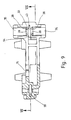
- Fig. 9
- die Fassung nach Fig. 6 in einer Draufsicht und teilweise geschnitten entlang der Linie IX-IX nach Fig. 8,
- Fig. 10
- eine Fassung ähnlich der nach Fig. 1 in einer Seitenansicht und teilweise geschnitten und
- Fig. 11
- die Fassung nach Fig. 10 im zusammengeklappten Zustand.
- Fig. 1
- a socket for a two-pin base lamp on both sides in a perspective view,
- Fig. 2
- 1, partially cut away and in an exploded view,
- Fig. 3
- 1 in a plan view of the lower housing leg and partially broken off,
- Fig. 4
- a version similar to that of FIG. 1 with the starter mount attached to the side,
- Fig. 5
- 4 in a rear view and in the open state,
- Fig. 6
- a perspective view of a holder to be used separately in a lamp housing,
- Fig. 7
- 6 in a view from the front,
- Fig. 8
- 4, cut along the line VIII-VIII of FIG. 9,
- Fig. 9
- 6 in a plan view and partially in section along the line IX-IX of FIG. 8,
- Fig. 10
- a version similar to that of FIG. 1 in a side view and partially cut and
- Fig. 11
- 10 in the folded state.
Fig. 1 zeigt eine Fassung 1 für an beiden Enden gesockelte
Leuchtstofflampen mit zwei Sockelstiften. Die Fassung 1
enthält ein Gehäuse 2 aus Isolierstoff, das,in der Seitenansicht
gesehen, etwa L-förmig ist. Es besteht aus
einem aufragenden ersten Gehäuseschenkel 3 sowie einem
liegenden zweiten Gehäuseschenkel 4, deren Längsachsen
sich rechtwinklig schneiden. Die beiden Gehäuseschenkel
3 und 4 gehen in einem Winkelbereich 5 einstückig ineinander
über. Sie haben jeder für sich eine im weitesten
Sinne quaderförmige Gestalt.Fig. 1 shows a
Der erste Gehäuseschenkel 3 ist von einer dem zweiten Gehäuseschenkel
4 zugekehrten Frontwand 6 begrenzt, an
der eine Seitenwandanordnung 7 einstückig angeformt ist.
Diese Seitenwandanordnung 7 bildet einen der Außenkontur
der Frontwand 6 weitgehend folgenden Kragen, der sich
zur Rückseite hin erhebt. Auf der Rückseite ist ein zu
dem ersten Gehäuseschenkel 3 gehöriger Deckel 8 aufgesetzt.
Dieser Deckel 8 endet bei einer Unterkante 9,
die höher liegt als es der Oberseite des zweiten Gehäuseschenkels
4 entspricht. Sie liegt etwa dort, wo der
erste Gehäuseschenkel 3 zwei symmetrisch angeordnete
Rücksprünge 11 aufweist, an denen sich der erste Gehäuseschenkel
3 hinsichtlich seiner Breite verjüngt. Im
Anschluß an die beiden Rücksprünge 11 geht der erste
Gehäuseschenkel 3 in zwei parallel zueinander verlaufende
Seitenwände 12 über.The
Die Frontwand 6 enthält in bekannter Weise eine zylindrische
Bohrung 13, in die von oben her ein auch die Seitenwandanordnung
7 durchsetzender Schlitz 14 einmündet. In
der Bohrung 13 ist ein im Querschnitt gesehen etwa T-förmiger
Drehkörper 15 drehbar gelagert, der dazu dient,
bei entnommener Lampe elektrisch leitende Teile innerhalb
der Fassung 1 unzugänglich zu verschließen. The
Der zweite Gehäuseschenkel 4 besteht aus einer im wesentlichen
ebenen Bodenplatte 16, die an ihrem dem ersten
Gehäuseschenkel 3 benachbarten Ende über die beiden parallel
mit Abstand zueinander verlaufende Seitenwände
12 mit dem ersten Gehäuseschenkel 3 verbunden ist. Seitlich
neben den beiden Seitenwänden 12 sind von der Bodenplatte
16 zwei in Richtung auf den ersten Gehäuseschenkel
3 weisende Arme 17 abgeteilt, die an ihrem
freien Ende einen nach unten weisenden Fuß 18 tragen.
Den Füßen 18 gegenüberliegend sind an der dem ersten
Gehäuseschenkel 3 abliegenden Seite der Bodenplatte 16
mit Abstand zueinander zwei Rastfüße 19 einstückig angeformt.
Die Füße 18 und die Rastfüße 19 weisen in die
gleiche Richtung, nämlich von der Bodenplatte 16 weg.The
Aus der dem ersten Gehäuseschenkel 3 zugekehrten Oberseite
der Bodenplatte 16 erheben sich insgesamt drei
Wände 21, 22, 23, die parallel mit Abstand zueinander
verlaufen und auch parallel zu einer durch die Frontseite
6 definierten Ebene sind. Diese drei Wände 21, 22
und 23 begrenzen zwei parallel nebeneinander verlaufende
Nuten 24 und 25. Ihre Oberkanten 26 sind jeweils eben
und liegen auf gleicher Höhe, wobei die Oberkante 26
der Wand 23 in eine Dachwand 27 übergeht, die einstückig
an die Frontwand 6 angeformt ist.From the top facing the
Unterhalb der Dachwand 27 gehen auch die Seitenwände 12
einstückig in die Wand 23 und in die Unterseite der Dachwand
27 über. Schließlich verlaufen zwischen den beiden
Seitenwänden 12 noch zwei Trennwände 28, die ebenfalls,
wie die Seitenwände 12, etwa L-förmig sind und sowohl an
die Rückseite der Frontwand 8, an die Unterseite der
Dachwand 27, die Rückseite der Wand 23 und die Oberseite
der Bodenplatte 16 angeformt sind. Ihre Hinterkante 29
springt gegenüber einer Hinterkante 31 der Seitenwände
12 geringfügig zurück, wobei die Hinterkanten 31 mit
der freien Kante der Seitenwandanordnung 7 bündig sind.The
Die Nut 24, deren Wand 21 sich nicht über die gesamte
Breite der Bodenplatte 16 erstreckt, wird etwa in ihrer
Mitte durch eine Kammer 33 in zwei etwa gleich lange
nutartige Vertiefungen 34 und 35 aufgesteilt, wobei jede
nutartige Vertiefung 34, 35 von zwei parallel zueinander
verlaufenden geraden Nutwänden 36 und 37 und einem
rechtwinklig dazu verlaufenden Nutenboden 32 begrenzt
wird, der gleichzeitig auch die Oberseite der Bodenplatte
16 ist.The
Die Kammer 33 wird von zwei parallel mit Abstand und
rechtwinklig zu den Nutenwänden 36, 37 verlaufenden Kammerwänden
38 begrenzt, die zueinander spiegelbildlich
sind. In beiden Kammerwänden 38, die jeweils von der
Oberkante 26 bis zu der Oberseite der Bodenplatte 16
reichen, sind miteinander fluchtende Einführschlitze
39 enthalten, die sich in der Mitte der betreffenden
Nut 24 befinden und bei 41 deutlich oberhalb der Bodenplatte
16 enden. Die Einführschlitze 39 in den beiden
Kammerwänden 38 erweitern sich an ihrem oberen Ende
bei 43 trichterförmig. Die Kammer 33 hat, wie insbesondere
die Fig. 3 erkennen läßt, im Lichtraumprofil
der Nut 24 eine etwas größere Weite, gemessen in Längsrichtung
der Nut 24 als in einem links von der Nut 24
liegenden Kammerabschnitt 43. Dieser Kammerabschnitt 43
ist ebenfalls parallelflankig begrenzt und reicht bis
zu der Oberseite der Bodenplatte 16 herunter.The
An ihrem, bezogen auf Fig. 3 rechten Ende, ist die Kammer
33 mit einem von der Oberkante 26 bis zu der Oberseite
der Bodenplatte 16 reichenden Schlitz 44 versehen,
der die Wand 26 vollständig durchsetzt. Dieser Schlitz
44 ist in Richtung auf die Nut 25 mit einer trichterförmigen
Erweiterung 45 versehen und enthält innerhalb der
Wand 26 eine von der Oberkante 26 bis zu der Oberseite
der Bodenplatte 16 reichende Erweiterung.At its right end, with respect to Fig. 3, is the
Der Schlitz 44 liegt symmetrisch bezüglich einer den
Kammerabschnitt 43 symmetrisch durchsetzenden und auf
der Bodenplatte 16 senkrecht stehenden Ebene. Ebenfalls
symmetrisch zu dieser Ebene befindet sich in einem
Rücksprung 46 in der Wand 23 eine rechteckige, allseits
umgrenzte Öffnung 47. Die Breite der Öffnung 47 entspricht
der lichten Weite des Schlitzes 44, während
die Höhe deutlich geringer ist als die Höhe der im
übrigen gleich hohen Wände 21, 22 und 23. An ihrem
unteren Ende geht die Öffnung 47 glatt in die Oberseite
der Bodenplatte 16 über. Schließlich liegt die Öffnung
47 symmetrisch zwischen der Trennwand 28 und der jeweils
benachbarten Seitenwand 12. Der Abstand, den die
Seitenwand 12 von der Trennwand 28 hat, ist größer als
es der Weite der Öffnung 47 entspricht.The
Schließlich sind an der Rückseite der Wand 23 kleine
Rippen angeformt, die von der Öffnung 47 ausgehen und
schräg zu der benachbarten Fläche der Trennwand 28
bzw. der Seitenwand 12 führen. Aus Darstellungsgründen
sind diese Rippen in den Figuren nicht erkennbar.Finally, there are 23 small ones at the back of the wall
Shaped ribs that extend from the
Eine weitere Kammer 48 ist in der Nut 25 vorhanden, und
zwar ist die Kammer 48 in Längsrichtung der Nut 25 gegenüber
der Kammer 33 versetzt. Die Kammer 48 wird in
gleicher Weise von zwei Kammerwänden 38 begrenzt, die
in der gleichen Weise gestaltet sind wie die Kammerwände
38 der Kammer 33 und weshalb insoweit gleiche Bezugszeichen
verwendet sind. Auch sie werden durch einen
Einführschlitz 39 teilweise durchsetzt.Another
Wie vorher weist die Kammer 48 einen Kammerabschnitt 43
auf, der jedoch in diesem Falle in der Wand 46 liegt. As before,
Der einzige Unterschied, der die Kammer 48 von der Kammer
33 unterscheidet, ist der Umstand, daß bei der Kammer 48
der Schlitz 44 unmittelbar in eine Öffnung 47 in der
Wand 23 übergeht, wobei jedoch auch diese Öffnung dieselbe
Gestalt hat wie die vorerwähnte Öffnung 47, lediglich
mit dem Unterschied, daß sie zwischen der anderen
Seitenwand 12 und der anderen Trennwand 28 liegt.
Zwischen den beiden Öffnungen 47 befinden sich somit
zwei parallel mit Abstand zueinander verlaufende Trennwände
28.The only difference that separates the
Im Inneren des Gehäuses 2 enthält die Fassung 1 zwei
weitgehend gleiche Kontaktfederanordnungen 49. Die gezeigte
Kontaktfederanordnung 49 ist zur Verwendung in
der Kammer 33 bestimmt. Sie weist eine Kontaktfederzunge
51, ein Verbindungsstück 52 und einen Schneidklemmkontakt
53 auf, die alle einstückig miteinander verbunden sind.Inside the
Der Schneidklemmkontakt 53 hat die Gestalt einer rechteckigen
Platte mit einer Höhe von ca. 8 mm und einer
Dicke von ca. 0,3 bis 0,5 mm. Er wird von zwei zueinander
parallelen Kanten 54 und 55 seitlich und oben und
unten von zwei Kanten 56 und 57 begrenzt. Die Kante 57
ist gerade und zu der Kante 56 parallel. Von letzterer
geht ein Schneidklemmschlitz 58 aus, der sich parallel
zu den Kanten 54 und 55 in Richtung auf die Unterkante
57 erstreckt. Die Höhe des Schneidklemmkontaktes 53,
gemessen zwischen der Unterkante 57 und der Oberkante 56,
ist geringfügig kleiner als die Höhe der Öffnung 47. Das
untere Ende des Schneidklemmschlitzes 58 hat dagegen
von der Unterkante 57 einen geringeren Abstand als
das untere Ende 41 des Einführschlitzes 39 von der
Oberseite der Bodenplatte 16. The
Um das Einführen des Leiters in den Schneidklemmschlitz
58 zu erleichtern, ist außerdem der Schneidklemmschlitz
58 in der Nähe der Oberkante 56 mit einer trichterartigen
Erweiterung 59 versehen.To insert the conductor into the
Das Verbindungsstück 52, das den Schneidklemmkontakt 53
einstückig mit der Kontaktfederzunge 51 verbindet, ist
etwa L-förmig und besteht aus einem unteren Schenkel
61, dessen Unterkante bündig in die Unterkante 57 übergeht
sowie einem oberen Schenkel 62, der rechtwinklig
zu dem Schenkel 61 angeordnet ist. Zwischen den beiden
Schenkeln 61 und 62 ist ein etwa unter 45° verlaufender
Abschnitt 63 eingefügt, von dem ein in den Zwickelbereich
zwischen den Schenkeln 61 und 62 vorspringender
Fortsatz 64 ausgeht. Die Höhe des Schenkels 61 ist so
bemessen, daß sie deutlich kleiner ist als der Abstand
des unteren Endes 41 des Einführschlitzes 39 von der
Oberseite der Bodenplatte 16. Das Zwischenstück 63 hat
abzüglich des Fortsatzes 64 etwa die gleiche Stärke wie
der Schenkel 61 und auch der Schenkel 62, der schließlich
rechtwinklig nach oben aufragt und in derselben
Ebene liegt wie der Schneidklemmkontakt 53, hat eine
Stärke entsprechend dem Schenkel 61.The
Die sich an das obere Ende des Schenkels 62 anschließende
Kontaktfederzunge 51 ist in ihrer Mitte bei 65
leicht V-förmig geknickt und ihre Breite ist an die
Länge der zu kontaktierenden Sockelstifte angepaßt, d.h.
ihre Breite entspricht etwa der lichten Weite zwischen
der Rückseite der Frontwand 6 und der Innenseite des
rückwärtigen Deckels 8.The adjoining the upper end of the
An ihrem oberen Ende geht die Konaktfederzunge 51 in
eine Lasche 66 über, mit der die Kontaktfederzunge 51
zwischen entsprechenden Rippen in dem ersten Gehäuseschenkel
3 in bekannter Weise gehalten ist. The
Der Fortsatz 64 wird von einer Ober- und einer Vorderkante
67 und 68 begrenzt, deren genaue Abmessungen sich aus
der nachfolgenden Montagebeschreibung ergeben.The
Die andere nicht sichtbare Kontaktfederanordnung 49 unterscheidet
sich hinsichtlich der Länge des Schenkels
61 von der gezeigten Ausführungsform, wie sich dies
ebenfalls aus der nachfolgenden Montagebeschreibung ergibt:The other invisible
Bei der Herstellung der gezeigten neuen Fassung wird in das
vorgefertigte Gehäuse 2 von der Rückseite des ersten Gehäuseschenkels
3 her die Kontaktfederanordnung 49 eingeschoben.
Dabei gleitet der Schneidklemmkontakt 53 mit
seiner Unterkante 57 auf der Oberseite der Bodenplatte
16 zwischen der in der Fig. 2 sichtbaren Trennwand 28
und der in Fig. 1 erkennbaren Seitenwand 12 hindurch.
Wird kurz vor der Öffnung 47 von den oben beschriebenen
Rippen in die Öffnung 47 eingefädelt und wird
von dort aus quer durch die Nut 25 hindurchgeschoben.
Die trichterförmige Erweiterung 45 an dem Schlitz 44
führt den Schneidklemmkontakt 53 in die Kammer 33 ein,
wobei seine Vorderkante 53 in dem Kammerabschnitt 43
zu liegen kommt. In dieser Endstellung stößt die Vorderkante
68 des Fortsatzes 64 an der Rückseite der Wand
23 oberhalb der Öffnung 47 an. Die Vorderkante 54 des
Schneidklemmkontaktes 53 dagegen steht in einem geringen
Abstand von der gegenüberliegenden Wand des Kammerfortsatzes
43. Gleichzeitig liegt in dieser Stellung die in
einer Ebene liegende Vorderkante der Kontaktfederzunge
51 und die sich damit in Verlängerung erstreckende Vorderkante
des Schenkels 62 an der Rückseite der Frontwand
6 an. Die Oberkante 67 des Fortsatzes 64 dagegen
liegt mit geringem Spiel unterhalb der Unterseite der
Dachwand 27. Die Lasche 66 ist schließlich zwischen entsprechenden
Rippen in dem Gehäuseschenkel 3 gefesselt. In the production of the new version shown in the
In dieser montierten Stellung führt der Schenkel 61
des Verbindungsstückes 52 blank liegend durch die Nut
25 hindurch. Allerdings geschieht dies in einem solchen
Abstand von den Oberkanten 26 der beiden Wände
22 und 23, daß eine Berührung ausgeschlossen ist. Auch
wird durch den durch die Nut 25 verlaufenden Abschnitt
des Schenkels 61 nicht die Isolation eines darüber
führenden Drahtes gefährdet, weil die Oberkante des
Schenkels 61 deutlich tiefer liegt als das untere
Ende des Einführschlitzes 39.In this assembled position, the
Die nicht sichtbare Kontaktfederanordnung 49 für die Kammer
48 hat, abgesehen von der Länge des Schenkels 61, wie
bereits erwähnt, dieselbe Gestalt wie die gezeigte Kontaktfederanordnung
49. Die Länge des Schenkels 61 ist
so bemessen, daß beim Einführen dieser Kontaktfederanordnung
in die andere, nicht sichtbare Öffnung 47 der
Schneidklemmkontakt 53, wie vorerwähnt, in der Kammer
48 zu liegen kommt, wenn die Vorderkante 68 des Fortsatzes
64 und die Vorderkante der Kontaktfederzunge
65 einerseits an der Rückseite der Wand 23 und andererseits
an der Rückseite der Frontwand 6 anstoßen.The invisible
Beim Einsetzen beider Kontaktfederanordnungen 49 gleitet
diese mit ihrer Unterkante 57 frei und ohne durch irgendwelche
Vorsprünge behindert zu sein, auf der Oberseite
der Bodenplatte 16 bis in die zugehörige Kammer 33 bzw. 48.
Beide Kontaktfederanordnungen 49 liegen in montiertem
Zustand mit ihrer Unterkante 57 flach auf der Oberseite
der Bodenplatte 16 auf, wobei der jeweilige Schneidklemmschlitz
58 mittig in dem Einführschlitz 39 der
beiden Kammerwände 38 steht. Das untere Ende des Schneidklemmschlitzes
58 verschwindet dabei unter der jeweiligen
Kammerwand 38. When inserting both
Nachdem die beiden Konaktfederanordnungen 49 eingesetzt
sind, wird in der üblichen Weise von vorne her der Drehkörper
15 eingesetzt und der Rückdeckel 8 aufgeschnappt.
Dadurch werden die beiden Kontaktfederanordnungen 49 zwischen
der Frontseite 6 und dem Rückdeckel 8 daran gehindert,
wieder aus dem Gehäuse 2 herausfallen zu können.After the two
Obzwar der Rückdeckel 8 den unteren Teil des ersten Gehäuseschenkels
3 und auch den sich daran anschließenden
Bereich des zweiten Gehäuseschenkels 4 nicht überdeckt
und somit ein Teil des Schenkels 62 sowie des Zwischenstücks
63 blank liegt, ist dennoch keine Gefahr gegeben,
weil die Seitenwände 12 in Verbindung mit den beiden
Trennwänden 28 einen Berührungsschutz sicherstellen.
Die Hinterkante des Schenkels 62 bzw. des Zwischenstücks
63 springen gegenüber den Hinterkanten 29 bzw.
31 so weit zurück, daß bei dem gegebenen Abstand zwischen
der Trennwand 28 und der jeweils benachbarten Seitenwand
12 die zum Prüfen der Berührungssicherheit übliche
Kugel die Kontaktfederanordnung 49 nicht erreichen
kann.Although the
Die Verdrahtung der neuen Fassung geschieht in der Weise,
daß mit Hilfe eines Werkzeugs ein nicht abisolierter
Leiter geeigneten Querschnitts und Außendurchmessers
von oben her in die jeweilige Kammer 33 eingepreßt wird.
Dabei schneidet der Schneidklemmkontakt 53 die Isolation
durch, die im übrigen zwischen den Rändern des Einführschlitzes
39 nur eingeklemmt wird. Die dabei auftretende
Montagekraft wird unmittelbar auf die Bodenplatte 16
übertragen. Es treten keine Kräfte auf, die bestrebt wären,
die Kontaktfederanordnung 49 entgegen der oben erwähnten
Einführbewegung bei der Montage der Fassung 1
wieder aus dem Gehäuse auszuwerfen. Dieses Ergebnis wird
dadurch erreicht, daß der Schneidklemmschlitz 38, der
die Kraftrichtung beim Kontaktieren festlegt, sich rechtwinklig
zu der Montagerichtung erstreckt, in der die Kontaktfederanordnung
49 in das Gehäuse 2 eingesetzt wird.The new version is wired in such a way
that with the help of a tool a non-stripped
Head of suitable cross-section and outside diameter
is pressed into the
Wie die Fig. 4 und 5 zeigen, kann die neue Lösung auch
bei Fassungen Anwendung finden, die in einem seitlichen
Arm 71 eine Fassungseinrichtung 72 für einen Lampenstarter
aufweisen. Bei dieser Fassung nach Fig. 4 hat der
zweite Gehäuseschenkel 4 dieselbe Gestalt wie bei der
Ausführungsform nach den Fig. 1 bis 3. Der erste Gehäuseschenkel
3 unterscheidet sich von der vorerwähnten Ausführungsform
lediglich dadurch, daß die Seitenwandanordnung
7 zur Bildung der Fassungseinrichtung 42 seitlich
ausgebuchtet ist. Ansonsten besteht kein Unterschied.
Schließlich enthält die Fassung nach Fig. 4 die
Kontaktfederanordnung 49 nach Fig. 2. Der Verlauf der
anderen Kontaktfederanordnung 49 und die Verbindungseinrichtung
für den Sockelstift und den entsprechenden
Starterstift zeigt in der Draufsicht Fig. 5.As shown in FIGS. 4 and 5, the new solution can also
are used for frames that are in a side
Arm 71 a
In dieser Rückansicht sind Bauteile, die bereits im Zusammenhang
mit den Fig. 1 bis 3 erläutert wurden und
in Fig. 5 wiederkehren, mit denselben Bezugszeichen versehen.
So erkannt man in Fig. 5 die Bodenplatte 16,
die beiden parallel mit Abstand voneinander aufragenden
Seitenwände 12, die dazwischen angeordneten Trennwände
28 und die zwischen jeweils einem Paar aus einer Trennwand
28 und einer Seitenwand 12 befindlichen rechteckigen
Öffnungen 47. In der linken dieser beiden Öffnungen
47 steckt die in Fig. 2 gezeigte Kontaktfederanordnung
49. Die Kontaktfederanordnung 73 unterscheidet sich von
der zweiten Kontaktfederanordnung der Ausführungsform
nach Fig. 2 insofern, als der Schenkel 62 knapp oberhalb
des Rücksprungs 11 nach rechts abgebogen ist und
von dort als gerade Zunge 74 zu einer der beiden schlüssellochartigen
Öffnungen 75 für die Startersockelstife
führt. Die Zunge 74 verläuft knapp durch das Lichtraumprofil
der unteren Öffnung 75 und wird durch in dem
seitlichen Teil 71 der Rückseite der Frontwand 6 angeformten
Leisten 76 gehalten. Die Zunge 74 liegt über
ihrer gesamten Länge an der Frontwand 6 von rückwärts
an.In this rear view are components that are already related
1 to 3 have been explained and
return in Fig. 5, provided with the same reference numerals.
The
Die zweite elektrische Verbindung zwischen der einzusetzenden
Lampe und dem Starter geschieht durch eine
Kontaktfederzunge 77, die einen ähnlich der Kontaktfederzunge
51 über die Bohrung 13 sich erstreckenden Abschnitt
78 aufweist, der oberhalb der Bohrung 13 nach
rechts in einen geraden Abschnitt 79 übergeht. Zur
Sicherung dieser Kontaktfeder 77 sind an der Peripherie
der Bohrung 13 entsprechende Rippen 81 vorgesehen, zwischen
denen der Abschnitt 78 hindurchführt. Sein unteres
Ende steckt in einer Tasche 82.The second electrical connection between the one to be used
Lamp and the starter happens through a
Ausgehend von den Rippen 81 führt der gerade Abschnitt 79
zu einer Abkröpfung 83 und von dort wiederum als ein
weiterer gerader Abschnitt 84 knapp durch das Lichtraumprofil
der oberen Öffnung 75. Im Bereich der oberen
Öffnung 75 ist der Abschnitt 84 durch weitere angeformte
Rippen 85 gehalten.The
Die Montage der Fassung nach den Fig. 4 und 5 sinngemäß wie dies oben bereits beschrieben ist.The assembly of the socket according to FIGS. 4 and 5 analogously as already described above.
Die Fig. 6 bis 9 zeigen eine Fassung 1, die dazu vorgesehen
ist, innerhalb eines Leuchtengehäuses einen Starter
oder ein anderes elektrisches Betriebsmittel mit
entsprechenden Sockelstiften zu haltern. Auch in diesem
Falle werden für Bauteile, die mit Bauteilen aus den
Fig. 1 bis 3 bzw. 5 und 6 funktionsgleich sind, dieselben
Bezugszeichen verwendet, um die Homologie zwischen
den Bauteilen besser erkennen zu können. 6 to 9 show a
Die Fassung 1 nach den Fig. 6 bis 9 besteht aus einem
einstückigen Gehäuse 2, das eine Vorderwand 87 sowie
eine Rückwand 88 aufweist, die über dazwischen verlaufende
Stege 89 bzw. Seitenwände 90 miteinander verbunden
sind, derart, daß zwischen der Vorder- und der
Rückwand 87, 88 ein hinreichend großer Zwischenraum
entsteht. Der Zwischenraum ist so bemessen, daß, wenn
ein Starter mit seinen Sockelstiften durch die schlüssellochförmigen
Öffnungen 75 in der Vorderwand 87 eingeführt
wird, die freien Enden der Sockelstifte nicht
an der Innenseite der Rückwand 88 anstoßen.The
Ferner sind neben den unteren beiden Ecken des Gehäuses
2 zwei nach unten weisende Rastglieder 19 angeformt,
die zusammen mit angeformten Aufstellfüßen 18 zur Befestigung
der Fassung 1 in einem entsprechenden Blechgehäuse
dienen.Also next to the bottom two corners of the
Neben den oberen beiden Ecken sind die beiden Kammern 33
für zwei galvanisch voneinander getrennte Schneidklemmkontakte
58 vorgesehen. Die beiden Kammern 33 sind exakt
spiegelsymmetrisch, so daß die nachfolgende Beschreibung
sinngemäß für beide Kammern 33 gilt.In addition to the top two corners, the two
Bei der Kammer 33 ist die eine Kammerwand 38 von der
Vorderwand 87 gebildet, während die andere rückwärtige
Kammerwand 38 ein in Richtung auf die Vorderwand 87 abgekröpfter
Bereich 88 ist. An beide Kammerwände 38 schließen
sich nach vorne und nach hinten Krägen 93 an, die
die nutenförmigen Vertiefungen 34 und 35 beidseits der
jeweiligen Kammer 33 begrenzen. Die beiden Krägen 93
bilden wiederum eine durchgehende Nut, die von der Kammer
33 unterbrochen ist. Unterschiedlich zu den vorherigen
Ausführungsbeispielen liegt bei dem Ausführungsbeispielen
nach den Fig. 6 bis 9 die Achse dieser von den nutartigen
Vertiefungen 34 und 35 definierte Nut senkrecht zu der
Vorderwand 27.In the
Wie am besten die Fig. 8 erkennen läßt, öffnet sich die
Kammer 33 an einem nach oben offenen Schlitz 94 in Richtung
auf den Innenraum zwischen der Vorderwand und der
Rückwand 87, 88, während unterhalb des Schlitzes 94
sich die Seitenwand 90 fortsetzt, die ansonsten den Innenraum
zwischen den beiden Wänden 87 und 88 zu beiden
Seiten hin verschließt.As best seen in FIG. 8, the
Die in den beiden Kammern 33 sitzenden Kontaktfederanordnungen
58 sind für die linke und die rechte Seite der
Fassung 1 spiegelsymmetrisch. Sie bestehen aus dem bereits
erläuterten Klemmschneidkontakt 53, der an seiner
Unterseite in eine Lasche 95 übergeht. Aus der Lasche 95
ist eine nach oben weisende Arretierungszunge 96 ausgeklinkt,
die dazu dient, die Klemmfederanordnung 58
unlösbar in der zugehörigen Kammer 33 zu halten.The contact spring arrangements seated in the two
In der Nähe der Oberkante 56 ist das Verbindungsstück 52
angeformt, das in die Kontaktfederzunge 51 übergeht. Die
Kontaktfederzunge 51 ist ein Blattfederstreifen, dessen
Breite gleich dem lichten Abstand zwischen der Vorderwand
87 und der Rückwand 88 ist. Die Ebene dieser Kontaktfederzunge
51 steht senkrecht auf der durch den Klemmschneidkontakt
53 definierten Ebene, d.h. sie ist, wie
die Draufsicht bei A zeigt, L-förmig aus der Ebene des
Klemmschneidkontaktes 53 herausgeboden.The
Die Montage der beschriebenen Fassung 1 geschieht einfach
in der Weise, daß in den das Gehäuse 2 bildenden einstückigen
Spritzgußteil die beiden Kontaktfederanordnungen
58 in die jeweilige Kammer 33 eingesteckt
werden. Der untere Teil jeder Kammer 33 ist taschenförmig
und nimmt den Fortsatz 95 auf. Dabei steht der Fortsatz
95 mit seiner Unterkante 97 auf einem Boden 98 der
Kammer 33 auf. In dieser Stellung schnappt die Rastzunge
96 in eine entsprechende Öffnung 99 in der Nähe des
unteren.Bodens 98 der jeweiligen Kammer 33. Da die
Rastzunge 96 nach oben gerichtet ist, ist nach dem
Einrasten der Rastzunge 96 ein Herausziehen der Kontaktfederanordnung
58 nach oben verhindert.Dagegen wird die
beim Kontaktieren auftretende Einpreßkraft, die entsteht,
wenn der Leiter in den Schneidklemmschlitz 58
eingedrückt ist, unmittelbar von dem Boden 98 auf das
Gehäuse 2 übertragen.The assembly of the described
Die Fig. 10 und 11 zeigen schließlich eine Ausführungsform,
bei der im Verlauf des Verbindungsstücks 49 der
Kontaktfederanordnung 49 eine Sollbiegestelle 101
enthalten ist. Auch bei diesem Ausführungsbeispiel
weist die Fassung 1 ein von der Seite gesehen L-förmiges
Gehäuse 2 auf, das von zwei miteinander verbundenen
Gehäuseschenkeln 3 und 4 gebildet ist. Der erste Gehäuseschenkel
3 besteht aus einer Seitenwandordnung 7,
an die diesmal eine Rückwand 102 einstückig angeformt
ist. Dagegen ist die Frontwand 6 mit dem darin eingesetzten
Drehkörper 15 als aufrastbarer Deckel ausgeführt.10 and 11 finally show an embodiment,
in the course of the
An ihrem von dem Drehkörper 15 abliegenden unteren Ende
geht die Rückwand 102 an einem Filmscharnier 103 in ein
Bodenteil 104 des zweiten Gehäuseschenkels 4 über. Der
Bodenteil 104 ist weitgehend plattenförmig und erstreckt
sich im montierten Zustand zwischen zwei seitlichen
Bodenleisten 105 des zweiten Gehäuseschenkels 4. Auf
dem mittleren klappbaren Bodenteil 104 befindet sich
eine Struktur aus Wänden, wie sie im Zusammenhang mit
Fig. 1 für den Gehäuseschenkel 4 erläutert ist. Außerdem
befinden sich zwischen diesen Wänden, deren axiale
Länge auf den Abstand zwischen den beiden Bodenleisten
105 beschränkt ist, die wiederum gegeneinander versetzten
Kammern 33 und 48. At its lower end remote from the rotating
Im Anschluß an die Kammern 33 und 48, dort, wo sich der
Schlitz 44 befindet, gehen genutete Stege 106 aus, die
auf dem Bodenteil 104 aufragend angeformt sind. In diesen
Stegen 106 befinden sich nutförmige Schlitze.Following the
Die in Verbindung mit diesem Ausführungsbeispiel zu
verwendende Kontaktfederanordnung 49 ist in Fig. 10
getrennt herausgezeichnet und läßt wiederum die bereits
erläuterte Kontaktfederzunge 51, die bei 65 geringfügig
V-förmig abgewinkelt ist, das Verbindungsstück 52 und
den Schneidklemmkontakt 53 erkennen. Der Schneidklemmkontakt
53 ist in der gleichen Weise gestaltet,wie
dies im Zusammenhang mit Fig. 2 erläutert ist und auch
die Kontaktfederzunge 51 hat den bereits erwähnten Aufbau.
Lediglich das Verbindungsstück 52 weicht in seiner
Konfiguration ab, insofern, als es an der entsprechenden
Stelle zwischen der Kontaktfederzunge 51 und den
Schneidklemmkontakt 53 mit der bereits erwähnten Sollbiegestelle
101 versehen ist, die dadurch entsteht, daß
die Breite bzw. Höhe des Blechstreifens, aus dem die
Kontaktfederanordnung 51 hergestellt ist, gegenüber den
übrigen Teilen des Verbindungsstückes 52 deutlich vermindert
ist.The in connection with this embodiment
Die beiden Kontaktfederanordnungen 49 für die beiden unterschiedlichen
Sockelstifte unterscheiden sich lediglich
in dem Abstand, den der Schneidklemmkontakt 53
von der Sollbiegestelle 101 hat.The two
Die Herstellung und Montage des Ausführungsbeispiels
nach den Fig. 10 und 11 ist folgendermaßen:The manufacture and assembly of the
Das Gehäuse 2 der Fassung 1 wird aus einem thermoplastischen
Kunststoffmaterial einstückig mit Ausnahme der als
Deckel ausgebildeten Frontseite 6 gespritzt, und zwar
in der in Fig. 10 erkennbaren Position. Dabei ragen die
beiden Bodenleisten 105 des zweiten Gehäuseschenkels 4,
bezogen auf die Rückwand 102, von dieser rechtwinklig
nach oben. Der dazwischen sich erstreckende Bodenteil
104 liegt demgegenüber in Verlängerung der Rückwand 102,
d.h. das Filmscharnier 103 ist gestreckt. Sodann werden
in die in den Stegen 106 enthaltenen Schlitze, die als
gerade Blechstanzteile ausgeführten Kontaktfederanordnungen
49 eingelegt, und zwar so, daß von einer
Kontaktfederanordnung 49 der Schneidklemmkontakt 53 in der
Kammer 48 und bei der anderen Kontaktfederanordnung 49
der Schneidklemmkontakt 53 in der anderen Kammer 33
liegt. Diese beiden Kammern haben unterschiedlichen Abstand
von dem Filmscharnier 103, und zwar sind sie in
der gleichen Weise gestaffelt, wie dies vorher im Zusammenhang
mit Fig. 1 erläutert ist. Sodann wird der
mittlere Bodenteil 104 zusammen mit den eingelegten
Kontaktfederanordnungen 49 im Uhrzeigersinne nach oben
gebogen, bis der Bodenteil 104 bündig zwischen den beiden
Bodenleisten 105 liegt.Dabei werden beide Kontaktfederanordnungen
49 an ihrer Sollbiegestelle 101 um eine
Achse verbogen, die senkrecht auf der durch die Flachseite
des Schneidklemmkontaktes 53 definierten Ebene
steht. Die Blechprofile werden sozusagen hochkant über
die Schmalseite verbogen.The
Nach dem Hochklappen des mittleren Bodenteils 104 verrastet
es mit nicht weiter gezeigten Rastgliedern in
der hochgeklappten Stellung, die in Fig. 11 zu sehen
ist. Im übrigen ist die Handhabung wie vorher erläutert.After folding up the
Claims (42)
- Socket (1) for electrical devices such as gas discharge lamps, fluorescent lamps or starters,with a housing (2) of insulating material;with at least one contact spring tab (51) arranged in the housing (2) which is adapted for contacting a contact arranged on the electrical device;with at least one essentially plate-like IDC contact (53), which is housed in the housing (2) and is accessible from the outside, with a IDC contact slit (58) open at the edge for clamping in a supply line having a width effecting a clamping fixture of a conductor of a pressed-in line;with an electrically conductive connecting portion (52) located between the contact spring tab (51) and the IDC contact (53), whereby the contact spring tab (51), the IDC contact (53) and the connecting portion (52) are integrally connected to one another and form a contact spring arrangement (58);with at least one chamber (33, 48) present in the housing (2) for the IDC contact (53), which chamber in its chamber walls (38) contains insertion slits (39) open at the edge and aligned to the IDC slit (58), in which chamber the IDC contact (53) is received in a manner protected against touch and on the base (16, 98) of which chamber the IDC contact (53) is supported, i.e. the IDC contact (53) stands on the bottom (16, 98) of the chamber; andwith protective webs (36, 37) arranged on both sides of each insertion slit (39), which form groove-like recesses (34, 35) extending towards the insertion slits (39) serving to protect against touch a possibly insulated conductor end projecting from the IDC slit (53).
- Socket according to Claim 1, characterised in that the width of the groove-like recess (34, 35) is greater than the outside diameter of a wire to be clamped in.
- Socket according to Claim 1, characterised in that the groove-like recess (34, 35) is deeper than the insertion slit (39).
- Socket according to Claim 1, characterised in that the insertion slit (39) has sharp edges.
- Socket according to Claim 1, characterised in that the IDC slit (58) widens out in a funnel shape at its open end.
- Socket according to Claim 1, characterised in that the insertion slit (39) widens out in a funnel shape at its open end.
- Socket according to Claim 1, characterised in that the housing (2) has integrally moulded attachment means (17, 18,19).
- Socket according to Claim 1, characterised in that the housing (2) has a first and a second housing leg (3, 4), which are both connected in one piece to one another in such a way that the housing (2) is approximately L-shaped viewed from the side; and that the longitudinal axes of the housing legs (3, 4) stand at right angles to one another.
- Socket according to Claim 8, characterised in that in its front wall (6) adjacent to the second housing leg (4), the first housing leg (3) has at least one opening (13) for the base or base pins of the electrical device.
- Socket according to Claim 9, characterised in that a rotary element (15) is rotationally mounted in the front wall (6) to receive a two-pin base lamp.
- Socket according to Claim 8, characterised in that the at least one chamber (33, 48) is provided for the IDC contact (53) in the second housing leg (4).
- Socket according to Claim 11, characterised in that the second housing leg (4) contains two chambers (33, 48) for two IDC contacts (53); that the groove-like recesses (34, 35) connected to the chambers (33, 48) respectively define two grooves (24, 25) open at the ends, which have a changing width over their length and with their longitudinal axis lie at right angles to the longitudinal axis of the second housing leg (4); that the grooves (34, 35) are at a distance from one another; and that the two chambers (33, 48) are offset with respect to one another viewed in the longitudinal direction of the grooves (24, 25).
- Socket according to Claim 12, characterised in that in extension of the chamber (33) of the other groove (24), the groove (25) more closely adjacent to the front wall (6) contains openings in its two groove side walls (36, 37), through which the IDC contact (53) may be inserted into its corresponding chamber (33) from the first housing leg (3).
- Socket according to Claim 13, characterised in that the openings (47) are adapted to the cross-sectional profile of the IDC contact (53).
- Socket according to Claim 13, characterised in that the chamber (33) and the adjacent groove (25) have bottoms, which lie at the same height; and that the openings (44;47) at the respective edge are flush with the bottoms.
- Socket according to Claim 13, characterised in that in the region between the front wall (6) and the groove (25) adjacent to it, the second housing leg (4) has a bottom (16), which are flush with the bottoms of the adjacent groove (24) and the chamber (33) lying on the other side of the groove (24).
- Socket according to Claim 11, characterised in that the chamber (48) in the groove (25) adjacent to the front wall (6) contains an opening (47), which opens towards the first housing leg (3) in such a way that the respective IDC contact (53) may be inserted into its chamber (33) from the first housing leg (3).
- Socket according to Claim 17, characterised in that in the region between the front wall and the groove (25) adjacent to it, the second housing leg (4) has a bottom (16) which is flush with the bottom of the respective chamber (48).
- Socket according to Claim 1, characterised in that in extension of the openings (47, 44) in the groove (25) adjacent to the front wall, the first housing leg (3) is open; and that at least one separating wall (28) extending from the rear side of the first housing leg (3) remote from the front wall (6) is arranged between the openings (47, 44), said separating wall (28) forming groove-like recesses serving to protect against touch together with side wall regions (12) of the first and second housing leg (3, 4).
- Socket according to Claim 19, characterised in that two separating walls (28) spaced from one another are provided which, together with side wall regions (12) of the first and second housing leg (3, 4), form groove-like recesses serving to protect against touch.
- Socket according to Claim 19 or 20, characterised in that the side wall regions (12) and the separating walls (28) bear ribs, which lead to the openings (44, 47) in the shape of a funnel.
- Socket according to Claim 8, characterised in that the first housing leg (3) has a base region (104), which is connected in one piece to the first housing leg (3) via a film hinge (101); and that the chambers (33, 48) and the groove-like recesses (34, 35) are arranged an the base region (104).
- Socket according to Claim 22, characterised in that webs run from the chambers (33, 48) towards a rear side (102) of the first housing leg (3) remote from the front wall (6), and grooves open to the top are contained in said webs, in which a part (52) of the respective contact spring arrangement (58) is located.
- Socket according to Claim 23, characterised in that the first housing leg (3) is closed at its rear side (102).
- Socket according to Claim 8, characterised in that laterally on the first housing leg (3), a housing extension (71) is provided which contains a further socket arrangement (72).
- Socket according to Claim 25, characterised in that the first socket arrangement (72) is a starter socket arrangement.
- Socket according to Claim 1, characterised in that the housing (2) essentially has the shape of a parallelepiped with a front wall (87), a rear wall (88) and side walls (90); and that at least one opening (75) is contained in the front wall (87) for the base or base pins of the electrical device.
- Socket according to Claim 27, characterised in that at least one chamber (33) is constructed in one of the side walls (90).
- Socket according to Claim 28, characterised in that two chambers (33) are constructed in one of the side walls (90) in the vicinity of the respective corners.
- Socket according to Claim 27, characterised in that the groove-like recesses (34, 35) pass through the front wall (87) and/or the rear wall (88).
- Socket according to Claim 1, characterised in that the insertion slit or slits (39) opens/open into a direction pointing away from the attachment means (17, 18, 19).
- Socket according to Claim 1, characterised in that the contact spring arrangement (49, 58) is a punched sheet metal element.
- Socket according to Claim 1, characterised in that the contact spring arrangement (49, 58) is an essentially L-shaped configuration.
- Socket according to Claim 1, characterised in that the IDC slit (58) points in the same direction as the contact spring tab (51).
- Socket according to Claim 1, characterised in that the connecting portion (52) has two legs (61, 62) running at right angles to one another and is tapered at the connection point (63).
- Socket according to Claim 35, characterised in that an extension (64) is provided in the angle area of the L-shaped configuration, its shoulder (67) pointing to the contact spring tab (51) lying higher with respect to a rear edge (57) of the IDC contact (53) than the opening of the IDC slit (58).
- Socket according to Claim 1, characterised in that the contact spring tab (51) lies essentially in the same plane as the IDC contact (53).
- Socket according to Claim 1, characterised in that the contact spring tab (51) lies in a plane, which is essentially at right angles to the plane in which the IDC contact (53) lies.
- Socket according to claim 1, characterised in that the connecting portion (52) merges into the IDC contact (53) at a region of the IDC contact (53) adjacent to the open end of the IDC slit (58).
- Socket according to Claim 1, characterised in that the connecting portion (52) contains a set bending point (101), which enables bending of the contact spring arrangement (49) relative to a bending axis standing perpendicular on the planes defined by the flat sides of the IDC contact (53).
- Socket according to Claims 22 and 40, characterised in that the set bending point (101) is situated close to the film hinge (103) when the contact spring arrangement (49) is inserted.
- Socket according to Claims 1 and 12, characterised in that at the point where it intersects the groove (25) of another contact spring arrangement, the connecting piece (52) is constructed so that its upper edge lies at a lower level relative to the base (16) of the groove (25) than the lower end of the IDC slit (58) of the other contact spring arrangement (49).
Applications Claiming Priority (2)
| Application Number | Priority Date | Filing Date | Title |
|---|---|---|---|
| DE4312776A DE4312776C2 (en) | 1993-04-20 | 1993-04-20 | Socket for electrical equipment |
| DE4312776 | 1993-04-20 |
Publications (3)
| Publication Number | Publication Date |
|---|---|
| EP0621661A2 EP0621661A2 (en) | 1994-10-26 |
| EP0621661A3 EP0621661A3 (en) | 1996-05-08 |
| EP0621661B1 true EP0621661B1 (en) | 1998-03-04 |
Family
ID=6485849
Family Applications (1)
| Application Number | Title | Priority Date | Filing Date |
|---|---|---|---|
| EP94100832A Expired - Lifetime EP0621661B1 (en) | 1993-04-20 | 1994-01-21 | Socket for electrical installation |
Country Status (8)
| Country | Link |
|---|---|
| US (1) | US5931691A (en) |
| EP (1) | EP0621661B1 (en) |
| JP (1) | JP3929506B2 (en) |
| AT (1) | ATE163809T1 (en) |
| AU (1) | AU678816B2 (en) |
| DE (2) | DE4312776C2 (en) |
| ES (1) | ES2113001T3 (en) |
| SG (1) | SG67288A1 (en) |
Cited By (2)
| Publication number | Priority date | Publication date | Assignee | Title |
|---|---|---|---|---|
| US8123540B2 (en) | 2008-10-01 | 2012-02-28 | Leviton Manufacturing Co., Inc. | Lamp socket having a rotor assembly |
| US8333602B2 (en) | 2011-01-06 | 2012-12-18 | Leviton Manufacturing Co., Inc. | Lamp socket having a rotor |
Families Citing this family (19)
| Publication number | Priority date | Publication date | Assignee | Title |
|---|---|---|---|---|
| DE19546797A1 (en) * | 1995-12-14 | 1997-06-19 | Amp Gmbh | Arrangement for contacting, in particular for contacting gas discharge lamps |
| DE19603374C2 (en) * | 1996-01-31 | 2000-12-07 | Vossloh Schwabe Gmbh | Self-contacting frame |
| DE19615373C2 (en) * | 1996-04-19 | 1998-07-02 | Vossloh Schwabe Gmbh | Socket, in particular for rod-shaped fluorescent tubes |
| DE19615372C2 (en) * | 1996-04-19 | 1998-07-16 | Vossloh Schwabe Gmbh | Mounting box with a lamp holder for two-pin fluorescent lamps or the like |
| DE29611509U1 (en) * | 1996-07-02 | 1996-09-05 | Norka Norddeutsche Kunststoff | Luminaire for rod-shaped, in particular double-ended, fluorescent lamps |
| DE19738461C2 (en) * | 1997-09-03 | 1999-09-23 | Vossloh Schwabe Gmbh | Spring-mounted lamp holder |
| DE19745762C1 (en) * | 1997-10-16 | 1999-08-26 | Vossloh Schwabe Gmbh | Fluorescent lamp holder with improved pin support |
| DE19920116C2 (en) * | 1999-05-03 | 2002-06-20 | Vossloh Schwabe Gmbh | start recording |
| DE10055148C2 (en) * | 2000-11-07 | 2003-05-22 | Phoenix Contact Gmbh & Co | Cable connection or connection device |
| JP3982996B2 (en) * | 2001-01-12 | 2007-09-26 | 矢崎総業株式会社 | Lamp socket and socket assembly |
| US7403999B2 (en) * | 2001-12-28 | 2008-07-22 | International Business Machines Corporation | Classification support system and method for fragmented IP packets |
| US7597575B2 (en) | 2005-09-13 | 2009-10-06 | Leviton Manufacturing Co., Inc. | Fluorescent lampholder |
| US20090196029A1 (en) * | 2008-02-05 | 2009-08-06 | Richard Kurtz | Discharge lamp and fixture therefor |
| US7549787B1 (en) | 2008-04-01 | 2009-06-23 | Lee Blaymore | Pivoting lock mechanism for fluorescent lamp sockets |
| US8113684B2 (en) | 2008-07-15 | 2012-02-14 | Leviton Manufacturing Co., Inc. | Fluorescent lamp support |
| US20110164414A1 (en) * | 2008-07-15 | 2011-07-07 | Robert Quercia | Fluorescent lamp support |
| DE102009003874B3 (en) * | 2009-05-04 | 2010-12-02 | Vossloh-Schwabe Deutschland Gmbh | Lamp holder for holding and contacting gas discharge lamp i.e. fluorescent lamp, has switch arranged in or at plastic housing for establishing or breaking connection to supply line through rotation of discharge lamp |
| CN103081256B (en) * | 2010-09-27 | 2015-10-07 | 东芝照明技术株式会社 | Lamp socket and lighting device |
| WO2014140999A1 (en) * | 2013-03-11 | 2014-09-18 | Koninklijke Philips N.V. | Adapter device for retrofitting in lighting arrangements |
Family Cites Families (17)
| Publication number | Priority date | Publication date | Assignee | Title |
|---|---|---|---|---|
| DE1137137B (en) * | 1954-01-11 | 1962-09-27 | Licentia Gmbh | Foldable socket for tubular lamps, especially fluorescent lamps |
| DE1020113B (en) * | 1954-03-15 | 1957-11-28 | Licentia Gmbh | Foldable socket of small axial depth for double-socket tubular lamps, especially fluorescent lamps |
| US3337837A (en) * | 1964-04-06 | 1967-08-22 | Gen Electric | Electric connector with torsion contacts |
| NL6617061A (en) * | 1966-12-03 | 1968-06-04 | ||
| DE1955977U (en) * | 1966-12-24 | 1967-02-23 | Broekelmann Jaeger & Busse K G | STARTING FEATURE. |
| US3654587A (en) * | 1970-01-15 | 1972-04-04 | Westinghouse Electric Corp | Fluorescent lampholder or the like |
| CA981352A (en) * | 1972-04-08 | 1976-01-06 | Roberto Plana | Electrical connectors |
| ES179115Y (en) * | 1972-04-08 | 1973-11-16 | Amp, Incorporated | A CONTACT ELEMENT OF METAL SHEET. |
| DE2559818C3 (en) * | 1975-04-15 | 1983-01-05 | Brökelmann, Jaeger & Busse GmbH & Co, 5760 Arnsberg | Socket for fluorescent lamps and process for their manufacture |
| CH652866A5 (en) * | 1981-11-04 | 1985-11-29 | Schurter Ag | LAMP SOCKET FOR BULBS WITH EDISON THREAD. |
| GB2114822A (en) * | 1982-02-10 | 1983-08-24 | Egyesuelt Izzolampa | Resilient socket for an electric light source |
| US5121310A (en) * | 1984-10-24 | 1992-06-09 | Ahroni Joseph M | Chaser decorative light set |
| US4807098A (en) * | 1984-10-24 | 1989-02-21 | Ahroni Joseph M | Lampholders for miniature light sets |
| DE3818517C2 (en) * | 1988-05-31 | 1995-01-12 | Siemens Ag | Lamp holder |
| DE8913917U1 (en) * | 1989-11-25 | 1991-03-21 | Parol Leuchtenkomponenten Gmbh, 4000 Duesseldorf, De | |
| DE4108390C1 (en) * | 1991-03-15 | 1992-03-12 | Hella Kg Hueck & Co, 4780 Lippstadt, De | Vehicle lamp fitting with several bulbs - has multiple plug connection consisting of several conducting tracks and housed in insulating part |
| DE4218740C2 (en) * | 1992-06-06 | 1995-07-06 | Vossloh Schwabe Gmbh | Electrical terminal device |
-
1993
- 1993-04-20 DE DE4312776A patent/DE4312776C2/en not_active Expired - Fee Related
-
1994
- 1994-01-21 EP EP94100832A patent/EP0621661B1/en not_active Expired - Lifetime
- 1994-01-21 ES ES94100832T patent/ES2113001T3/en not_active Expired - Lifetime
- 1994-01-21 AT AT94100832T patent/ATE163809T1/en active
- 1994-01-21 DE DE59405331T patent/DE59405331D1/en not_active Expired - Lifetime
- 1994-01-21 SG SG1996001247A patent/SG67288A1/en unknown
- 1994-04-19 AU AU60568/94A patent/AU678816B2/en not_active Ceased
- 1994-04-20 JP JP08188394A patent/JP3929506B2/en not_active Expired - Fee Related
-
1996
- 1996-08-21 US US08/701,198 patent/US5931691A/en not_active Expired - Fee Related
Cited By (2)
| Publication number | Priority date | Publication date | Assignee | Title |
|---|---|---|---|---|
| US8123540B2 (en) | 2008-10-01 | 2012-02-28 | Leviton Manufacturing Co., Inc. | Lamp socket having a rotor assembly |
| US8333602B2 (en) | 2011-01-06 | 2012-12-18 | Leviton Manufacturing Co., Inc. | Lamp socket having a rotor |
Also Published As
| Publication number | Publication date |
|---|---|
| JP3929506B2 (en) | 2007-06-13 |
| EP0621661A3 (en) | 1996-05-08 |
| AU678816B2 (en) | 1997-06-12 |
| DE4312776A1 (en) | 1994-12-08 |
| AU6056894A (en) | 1994-10-27 |
| EP0621661A2 (en) | 1994-10-26 |
| DE4312776C2 (en) | 1995-08-31 |
| US5931691A (en) | 1999-08-03 |
| SG67288A1 (en) | 1999-09-21 |
| ES2113001T3 (en) | 1998-04-16 |
| JPH07122338A (en) | 1995-05-12 |
| ATE163809T1 (en) | 1998-03-15 |
| DE59405331D1 (en) | 1998-04-09 |
Similar Documents
| Publication | Publication Date | Title |
|---|---|---|
| EP0621661B1 (en) | Socket for electrical installation | |
| EP0678932B1 (en) | Electrical junction and connection terminal | |
| EP2672576B1 (en) | Connector for data transmission via electrical wires | |
| DE2414640A1 (en) | ELECTRIC TERMINAL | |
| DE2212807C2 (en) | Electrical connector assembly | |
| EP0311769A2 (en) | Miniaturized spring contact plug | |
| DE3009675C2 (en) | ||
| DE202019105009U1 (en) | Conductor connection terminal | |
| EP0758808B1 (en) | System of lamp holder for fluorescent lamps | |
| DE3928751C2 (en) | ||
| DE202005014577U1 (en) | Connecting terminal for a bus bar has an electrically insulated casing with an electrically conductive exposed terminal and clamping screws | |
| DE2536135A1 (en) | ELECTRICAL CONNECTION ARRANGEMENT | |
| DE19949387B4 (en) | Contact part for connection terminal | |
| DE3345128C2 (en) | ||
| DE4312781C2 (en) | Connection element for at least one electrical equipment | |
| DE3224954A1 (en) | PLUG-IN CARD BASE | |
| EP0220394A2 (en) | Electrical connector | |
| DE2346072A1 (en) | CONNECTION CLAMP FOR AN ELECTRICAL CONNECTION | |
| DE102014114352B3 (en) | pin header | |
| EP0892997B1 (en) | Cable plug connector | |
| EP0568899B1 (en) | Multipole cable plug | |
| DE3306219C2 (en) | Switches, in particular for motor vehicles | |
| DE8420661U1 (en) | Electrical auxiliary connection | |
| EP1333535A2 (en) | Safety socket with the finger-proof contact protection fixed on the socket cover | |
| DE3030906C2 (en) | Switching plug device with a jumper plug |
Legal Events
| Date | Code | Title | Description |
|---|---|---|---|
| PUAI | Public reference made under article 153(3) epc to a published international application that has entered the european phase |
Free format text: ORIGINAL CODE: 0009012 |
|
| AK | Designated contracting states |
Kind code of ref document: A2 Designated state(s): AT CH DE ES FR GB IT LI NL SE |
|
| PUAL | Search report despatched |
Free format text: ORIGINAL CODE: 0009013 |
|
| AK | Designated contracting states |
Kind code of ref document: A3 Designated state(s): AT CH DE ES FR GB IT LI NL SE |
|
| 17P | Request for examination filed |
Effective date: 19961009 |
|
| GRAG | Despatch of communication of intention to grant |
Free format text: ORIGINAL CODE: EPIDOS AGRA |
|
| GRAG | Despatch of communication of intention to grant |
Free format text: ORIGINAL CODE: EPIDOS AGRA |
|
| GRAH | Despatch of communication of intention to grant a patent |
Free format text: ORIGINAL CODE: EPIDOS IGRA |
|
| 17Q | First examination report despatched |
Effective date: 19970728 |
|
| GRAH | Despatch of communication of intention to grant a patent |
Free format text: ORIGINAL CODE: EPIDOS IGRA |
|
| GRAA | (expected) grant |
Free format text: ORIGINAL CODE: 0009210 |
|
| AK | Designated contracting states |
Kind code of ref document: B1 Designated state(s): AT CH DE ES FR GB IT LI NL SE |
|
| REF | Corresponds to: |
Ref document number: 163809 Country of ref document: AT Date of ref document: 19980315 Kind code of ref document: T |
|
| REG | Reference to a national code |
Ref country code: CH Ref legal event code: NV Representative=s name: KIRKER & CIE SA Ref country code: CH Ref legal event code: EP |
|
| GBT | Gb: translation of ep patent filed (gb section 77(6)(a)/1977) |
Effective date: 19980305 |
|
| REF | Corresponds to: |
Ref document number: 59405331 Country of ref document: DE Date of ref document: 19980409 |
|
| REG | Reference to a national code |
Ref country code: ES Ref legal event code: FG2A Ref document number: 2113001 Country of ref document: ES Kind code of ref document: T3 |
|
| ITF | It: translation for a ep patent filed |
Owner name: JACOBACCI & PERANI S.P.A. |
|
| ET | Fr: translation filed | ||
| PLBE | No opposition filed within time limit |
Free format text: ORIGINAL CODE: 0009261 |
|
| STAA | Information on the status of an ep patent application or granted ep patent |
Free format text: STATUS: NO OPPOSITION FILED WITHIN TIME LIMIT |
|
| 26N | No opposition filed | ||
| REG | Reference to a national code |
Ref country code: GB Ref legal event code: IF02 |
|
| NLT1 | Nl: modifications of names registered in virtue of documents presented to the patent office pursuant to art. 16 a, paragraph 1 |
Owner name: VOSSLOH-SCHWABE DEUTSCHLAND GMBH |
|
| REG | Reference to a national code |
Ref country code: CH Ref legal event code: PFA Owner name: VOSSLOH-SCHWABE DEUTSCHLAND GMBH Free format text: VOSSLOH SCHWABE GMBH#WASENSTRASSE 25#D-73660 URBACH (DE) -TRANSFER TO- VOSSLOH-SCHWABE DEUTSCHLAND GMBH#HOHE STEINERT 8#58509 LUEDENSCHEID (DE) |
|
| PGFP | Annual fee paid to national office [announced via postgrant information from national office to epo] |
Ref country code: SE Payment date: 20110113 Year of fee payment: 18 Ref country code: CH Payment date: 20110124 Year of fee payment: 18 Ref country code: AT Payment date: 20110113 Year of fee payment: 18 Ref country code: NL Payment date: 20110117 Year of fee payment: 18 |
|
| PGFP | Annual fee paid to national office [announced via postgrant information from national office to epo] |
Ref country code: FR Payment date: 20120206 Year of fee payment: 19 |
|
| PGFP | Annual fee paid to national office [announced via postgrant information from national office to epo] |
Ref country code: DE Payment date: 20120131 Year of fee payment: 19 |
|
| PGFP | Annual fee paid to national office [announced via postgrant information from national office to epo] |
Ref country code: GB Payment date: 20120120 Year of fee payment: 19 Ref country code: IT Payment date: 20120126 Year of fee payment: 19 |
|
| REG | Reference to a national code |
Ref country code: NL Ref legal event code: V1 Effective date: 20120801 |
|
| REG | Reference to a national code |
Ref country code: CH Ref legal event code: PL |
|
| REG | Reference to a national code |
Ref country code: SE Ref legal event code: EUG |
|
| PG25 | Lapsed in a contracting state [announced via postgrant information from national office to epo] |
Ref country code: SE Free format text: LAPSE BECAUSE OF NON-PAYMENT OF DUE FEES Effective date: 20120122 Ref country code: CH Free format text: LAPSE BECAUSE OF NON-PAYMENT OF DUE FEES Effective date: 20120131 Ref country code: LI Free format text: LAPSE BECAUSE OF NON-PAYMENT OF DUE FEES Effective date: 20120131 |
|
| REG | Reference to a national code |
Ref country code: AT Ref legal event code: MM01 Ref document number: 163809 Country of ref document: AT Kind code of ref document: T Effective date: 20120121 |
|
| PG25 | Lapsed in a contracting state [announced via postgrant information from national office to epo] |
Ref country code: AT Free format text: LAPSE BECAUSE OF NON-PAYMENT OF DUE FEES Effective date: 20120121 Ref country code: NL Free format text: LAPSE BECAUSE OF NON-PAYMENT OF DUE FEES Effective date: 20120801 |
|
| PGFP | Annual fee paid to national office [announced via postgrant information from national office to epo] |
Ref country code: ES Payment date: 20120126 Year of fee payment: 19 |
|
| GBPC | Gb: european patent ceased through non-payment of renewal fee |
Effective date: 20130121 |
|
| REG | Reference to a national code |
Ref country code: FR Ref legal event code: ST Effective date: 20130930 |
|
| PG25 | Lapsed in a contracting state [announced via postgrant information from national office to epo] |
Ref country code: DE Free format text: LAPSE BECAUSE OF NON-PAYMENT OF DUE FEES Effective date: 20130801 |
|
| REG | Reference to a national code |
Ref country code: DE Ref legal event code: R119 Ref document number: 59405331 Country of ref document: DE Effective date: 20130801 |
|
| PG25 | Lapsed in a contracting state [announced via postgrant information from national office to epo] |
Ref country code: FR Free format text: LAPSE BECAUSE OF NON-PAYMENT OF DUE FEES Effective date: 20130131 Ref country code: GB Free format text: LAPSE BECAUSE OF NON-PAYMENT OF DUE FEES Effective date: 20130121 |
|
| PG25 | Lapsed in a contracting state [announced via postgrant information from national office to epo] |
Ref country code: IT Free format text: LAPSE BECAUSE OF NON-PAYMENT OF DUE FEES Effective date: 20130121 |
|
| REG | Reference to a national code |
Ref country code: ES Ref legal event code: FD2A Effective date: 20140324 |
|
| PG25 | Lapsed in a contracting state [announced via postgrant information from national office to epo] |
Ref country code: ES Free format text: LAPSE BECAUSE OF NON-PAYMENT OF DUE FEES Effective date: 20130122 |