EP0617633B1 - Detachable embolic coil assembly - Google Patents
Detachable embolic coil assembly Download PDFInfo
- Publication number
- EP0617633B1 EP0617633B1 EP93922153A EP93922153A EP0617633B1 EP 0617633 B1 EP0617633 B1 EP 0617633B1 EP 93922153 A EP93922153 A EP 93922153A EP 93922153 A EP93922153 A EP 93922153A EP 0617633 B1 EP0617633 B1 EP 0617633B1
- Authority
- EP
- European Patent Office
- Prior art keywords
- coil
- pusher
- catheter
- assembly
- coils
- Prior art date
- Legal status (The legal status is an assumption and is not a legal conclusion. Google has not performed a legal analysis and makes no representation as to the accuracy of the status listed.)
- Expired - Lifetime
Links
Images


Classifications
-
- A—HUMAN NECESSITIES
- A61—MEDICAL OR VETERINARY SCIENCE; HYGIENE
- A61F—FILTERS IMPLANTABLE INTO BLOOD VESSELS; PROSTHESES; DEVICES PROVIDING PATENCY TO, OR PREVENTING COLLAPSING OF, TUBULAR STRUCTURES OF THE BODY, e.g. STENTS; ORTHOPAEDIC, NURSING OR CONTRACEPTIVE DEVICES; FOMENTATION; TREATMENT OR PROTECTION OF EYES OR EARS; BANDAGES, DRESSINGS OR ABSORBENT PADS; FIRST-AID KITS
- A61F2/00—Filters implantable into blood vessels; Prostheses, i.e. artificial substitutes or replacements for parts of the body; Appliances for connecting them with the body; Devices providing patency to, or preventing collapsing of, tubular structures of the body, e.g. stents
- A61F2/01—Filters implantable into blood vessels
-
- A—HUMAN NECESSITIES
- A61—MEDICAL OR VETERINARY SCIENCE; HYGIENE
- A61L—METHODS OR APPARATUS FOR STERILISING MATERIALS OR OBJECTS IN GENERAL; DISINFECTION, STERILISATION OR DEODORISATION OF AIR; CHEMICAL ASPECTS OF BANDAGES, DRESSINGS, ABSORBENT PADS OR SURGICAL ARTICLES; MATERIALS FOR BANDAGES, DRESSINGS, ABSORBENT PADS OR SURGICAL ARTICLES
- A61L31/00—Materials for other surgical articles, e.g. stents, stent-grafts, shunts, surgical drapes, guide wires, materials for adhesion prevention, occluding devices, surgical gloves, tissue fixation devices
- A61L31/02—Inorganic materials
- A61L31/022—Metals or alloys
-
- A—HUMAN NECESSITIES
- A61—MEDICAL OR VETERINARY SCIENCE; HYGIENE
- A61B—DIAGNOSIS; SURGERY; IDENTIFICATION
- A61B17/00—Surgical instruments, devices or methods, e.g. tourniquets
- A61B17/12—Surgical instruments, devices or methods, e.g. tourniquets for ligaturing or otherwise compressing tubular parts of the body, e.g. blood vessels, umbilical cord
- A61B17/12022—Occluding by internal devices, e.g. balloons or releasable wires
- A61B17/12131—Occluding by internal devices, e.g. balloons or releasable wires characterised by the type of occluding device
- A61B17/1214—Coils or wires
- A61B17/12145—Coils or wires having a pre-set deployed three-dimensional shape
-
- A—HUMAN NECESSITIES
- A61—MEDICAL OR VETERINARY SCIENCE; HYGIENE
- A61B—DIAGNOSIS; SURGERY; IDENTIFICATION
- A61B18/00—Surgical instruments, devices or methods for transferring non-mechanical forms of energy to or from the body
- A61B18/04—Surgical instruments, devices or methods for transferring non-mechanical forms of energy to or from the body by heating
- A61B18/12—Surgical instruments, devices or methods for transferring non-mechanical forms of energy to or from the body by heating by passing a current through the tissue to be heated, e.g. high-frequency current
- A61B18/14—Probes or electrodes therefor
- A61B18/1492—Probes or electrodes therefor having a flexible, catheter-like structure, e.g. for heart ablation
-
- A—HUMAN NECESSITIES
- A61—MEDICAL OR VETERINARY SCIENCE; HYGIENE
- A61F—FILTERS IMPLANTABLE INTO BLOOD VESSELS; PROSTHESES; DEVICES PROVIDING PATENCY TO, OR PREVENTING COLLAPSING OF, TUBULAR STRUCTURES OF THE BODY, e.g. STENTS; ORTHOPAEDIC, NURSING OR CONTRACEPTIVE DEVICES; FOMENTATION; TREATMENT OR PROTECTION OF EYES OR EARS; BANDAGES, DRESSINGS OR ABSORBENT PADS; FIRST-AID KITS
- A61F2/00—Filters implantable into blood vessels; Prostheses, i.e. artificial substitutes or replacements for parts of the body; Appliances for connecting them with the body; Devices providing patency to, or preventing collapsing of, tubular structures of the body, e.g. stents
- A61F2/01—Filters implantable into blood vessels
- A61F2/011—Instruments for their placement or removal
-
- A—HUMAN NECESSITIES
- A61—MEDICAL OR VETERINARY SCIENCE; HYGIENE
- A61F—FILTERS IMPLANTABLE INTO BLOOD VESSELS; PROSTHESES; DEVICES PROVIDING PATENCY TO, OR PREVENTING COLLAPSING OF, TUBULAR STRUCTURES OF THE BODY, e.g. STENTS; ORTHOPAEDIC, NURSING OR CONTRACEPTIVE DEVICES; FOMENTATION; TREATMENT OR PROTECTION OF EYES OR EARS; BANDAGES, DRESSINGS OR ABSORBENT PADS; FIRST-AID KITS
- A61F2/00—Filters implantable into blood vessels; Prostheses, i.e. artificial substitutes or replacements for parts of the body; Appliances for connecting them with the body; Devices providing patency to, or preventing collapsing of, tubular structures of the body, e.g. stents
- A61F2/01—Filters implantable into blood vessels
- A61F2/012—Multiple filtering units
-
- A—HUMAN NECESSITIES
- A61—MEDICAL OR VETERINARY SCIENCE; HYGIENE
- A61L—METHODS OR APPARATUS FOR STERILISING MATERIALS OR OBJECTS IN GENERAL; DISINFECTION, STERILISATION OR DEODORISATION OF AIR; CHEMICAL ASPECTS OF BANDAGES, DRESSINGS, ABSORBENT PADS OR SURGICAL ARTICLES; MATERIALS FOR BANDAGES, DRESSINGS, ABSORBENT PADS OR SURGICAL ARTICLES
- A61L31/00—Materials for other surgical articles, e.g. stents, stent-grafts, shunts, surgical drapes, guide wires, materials for adhesion prevention, occluding devices, surgical gloves, tissue fixation devices
- A61L31/02—Inorganic materials
- A61L31/024—Carbon; Graphite
-
- A—HUMAN NECESSITIES
- A61—MEDICAL OR VETERINARY SCIENCE; HYGIENE
- A61L—METHODS OR APPARATUS FOR STERILISING MATERIALS OR OBJECTS IN GENERAL; DISINFECTION, STERILISATION OR DEODORISATION OF AIR; CHEMICAL ASPECTS OF BANDAGES, DRESSINGS, ABSORBENT PADS OR SURGICAL ARTICLES; MATERIALS FOR BANDAGES, DRESSINGS, ABSORBENT PADS OR SURGICAL ARTICLES
- A61L31/00—Materials for other surgical articles, e.g. stents, stent-grafts, shunts, surgical drapes, guide wires, materials for adhesion prevention, occluding devices, surgical gloves, tissue fixation devices
- A61L31/04—Macromolecular materials
-
- A—HUMAN NECESSITIES
- A61—MEDICAL OR VETERINARY SCIENCE; HYGIENE
- A61B—DIAGNOSIS; SURGERY; IDENTIFICATION
- A61B17/00—Surgical instruments, devices or methods, e.g. tourniquets
- A61B17/12—Surgical instruments, devices or methods, e.g. tourniquets for ligaturing or otherwise compressing tubular parts of the body, e.g. blood vessels, umbilical cord
- A61B17/12022—Occluding by internal devices, e.g. balloons or releasable wires
- A61B2017/1205—Introduction devices
- A61B2017/12054—Details concerning the detachment of the occluding device from the introduction device
-
- A—HUMAN NECESSITIES
- A61—MEDICAL OR VETERINARY SCIENCE; HYGIENE
- A61B—DIAGNOSIS; SURGERY; IDENTIFICATION
- A61B18/00—Surgical instruments, devices or methods for transferring non-mechanical forms of energy to or from the body
- A61B2018/00315—Surgical instruments, devices or methods for transferring non-mechanical forms of energy to or from the body for treatment of particular body parts
- A61B2018/00345—Vascular system
- A61B2018/00404—Blood vessels other than those in or around the heart
-
- A—HUMAN NECESSITIES
- A61—MEDICAL OR VETERINARY SCIENCE; HYGIENE
- A61B—DIAGNOSIS; SURGERY; IDENTIFICATION
- A61B18/00—Surgical instruments, devices or methods for transferring non-mechanical forms of energy to or from the body
- A61B18/04—Surgical instruments, devices or methods for transferring non-mechanical forms of energy to or from the body by heating
- A61B18/12—Surgical instruments, devices or methods for transferring non-mechanical forms of energy to or from the body by heating by passing a current through the tissue to be heated, e.g. high-frequency current
- A61B18/14—Probes or electrodes therefor
- A61B2018/1495—Electrodes being detachable from a support structure
-
- A—HUMAN NECESSITIES
- A61—MEDICAL OR VETERINARY SCIENCE; HYGIENE
- A61F—FILTERS IMPLANTABLE INTO BLOOD VESSELS; PROSTHESES; DEVICES PROVIDING PATENCY TO, OR PREVENTING COLLAPSING OF, TUBULAR STRUCTURES OF THE BODY, e.g. STENTS; ORTHOPAEDIC, NURSING OR CONTRACEPTIVE DEVICES; FOMENTATION; TREATMENT OR PROTECTION OF EYES OR EARS; BANDAGES, DRESSINGS OR ABSORBENT PADS; FIRST-AID KITS
- A61F2/00—Filters implantable into blood vessels; Prostheses, i.e. artificial substitutes or replacements for parts of the body; Appliances for connecting them with the body; Devices providing patency to, or preventing collapsing of, tubular structures of the body, e.g. stents
- A61F2/01—Filters implantable into blood vessels
- A61F2002/016—Filters implantable into blood vessels made from wire-like elements
-
- A—HUMAN NECESSITIES
- A61—MEDICAL OR VETERINARY SCIENCE; HYGIENE
- A61F—FILTERS IMPLANTABLE INTO BLOOD VESSELS; PROSTHESES; DEVICES PROVIDING PATENCY TO, OR PREVENTING COLLAPSING OF, TUBULAR STRUCTURES OF THE BODY, e.g. STENTS; ORTHOPAEDIC, NURSING OR CONTRACEPTIVE DEVICES; FOMENTATION; TREATMENT OR PROTECTION OF EYES OR EARS; BANDAGES, DRESSINGS OR ABSORBENT PADS; FIRST-AID KITS
- A61F2230/00—Geometry of prostheses classified in groups A61F2/00 - A61F2/26 or A61F2/82 or A61F9/00 or A61F11/00 or subgroups thereof
- A61F2230/0002—Two-dimensional shapes, e.g. cross-sections
- A61F2230/0004—Rounded shapes, e.g. with rounded corners
- A61F2230/0006—Rounded shapes, e.g. with rounded corners circular
-
- A—HUMAN NECESSITIES
- A61—MEDICAL OR VETERINARY SCIENCE; HYGIENE
- A61F—FILTERS IMPLANTABLE INTO BLOOD VESSELS; PROSTHESES; DEVICES PROVIDING PATENCY TO, OR PREVENTING COLLAPSING OF, TUBULAR STRUCTURES OF THE BODY, e.g. STENTS; ORTHOPAEDIC, NURSING OR CONTRACEPTIVE DEVICES; FOMENTATION; TREATMENT OR PROTECTION OF EYES OR EARS; BANDAGES, DRESSINGS OR ABSORBENT PADS; FIRST-AID KITS
- A61F2230/00—Geometry of prostheses classified in groups A61F2/00 - A61F2/26 or A61F2/82 or A61F9/00 or A61F11/00 or subgroups thereof
- A61F2230/0002—Two-dimensional shapes, e.g. cross-sections
- A61F2230/0028—Shapes in the form of latin or greek characters
- A61F2230/005—Rosette-shaped, e.g. star-shaped
-
- A—HUMAN NECESSITIES
- A61—MEDICAL OR VETERINARY SCIENCE; HYGIENE
- A61F—FILTERS IMPLANTABLE INTO BLOOD VESSELS; PROSTHESES; DEVICES PROVIDING PATENCY TO, OR PREVENTING COLLAPSING OF, TUBULAR STRUCTURES OF THE BODY, e.g. STENTS; ORTHOPAEDIC, NURSING OR CONTRACEPTIVE DEVICES; FOMENTATION; TREATMENT OR PROTECTION OF EYES OR EARS; BANDAGES, DRESSINGS OR ABSORBENT PADS; FIRST-AID KITS
- A61F2230/00—Geometry of prostheses classified in groups A61F2/00 - A61F2/26 or A61F2/82 or A61F9/00 or A61F11/00 or subgroups thereof
- A61F2230/0002—Two-dimensional shapes, e.g. cross-sections
- A61F2230/0028—Shapes in the form of latin or greek characters
- A61F2230/0058—X-shaped
-
- A—HUMAN NECESSITIES
- A61—MEDICAL OR VETERINARY SCIENCE; HYGIENE
- A61F—FILTERS IMPLANTABLE INTO BLOOD VESSELS; PROSTHESES; DEVICES PROVIDING PATENCY TO, OR PREVENTING COLLAPSING OF, TUBULAR STRUCTURES OF THE BODY, e.g. STENTS; ORTHOPAEDIC, NURSING OR CONTRACEPTIVE DEVICES; FOMENTATION; TREATMENT OR PROTECTION OF EYES OR EARS; BANDAGES, DRESSINGS OR ABSORBENT PADS; FIRST-AID KITS
- A61F2230/00—Geometry of prostheses classified in groups A61F2/00 - A61F2/26 or A61F2/82 or A61F9/00 or A61F11/00 or subgroups thereof
- A61F2230/0063—Three-dimensional shapes
- A61F2230/0091—Three-dimensional shapes helically-coiled or spirally-coiled, i.e. having a 2-D spiral cross-section
-
- A—HUMAN NECESSITIES
- A61—MEDICAL OR VETERINARY SCIENCE; HYGIENE
- A61L—METHODS OR APPARATUS FOR STERILISING MATERIALS OR OBJECTS IN GENERAL; DISINFECTION, STERILISATION OR DEODORISATION OF AIR; CHEMICAL ASPECTS OF BANDAGES, DRESSINGS, ABSORBENT PADS OR SURGICAL ARTICLES; MATERIALS FOR BANDAGES, DRESSINGS, ABSORBENT PADS OR SURGICAL ARTICLES
- A61L2430/00—Materials or treatment for tissue regeneration
- A61L2430/36—Materials or treatment for tissue regeneration for embolization or occlusion, e.g. vaso-occlusive compositions or devices
Definitions
- WO-A-92/21400 and WO-A-93/11825 are both relevant as prior art against the present invention under Article 54(3) EPC at most. Both references disclose detachable pusher-vasoocclusive coil assemblies in which the proximal end of the vasoocclusive coil is provided with a ball of smaller diameter than the coil. This ball is interlocked, either in a keyway in or between a pair of radially expandable jaws provided at the distal end of a pusher.
- the pusher-vasoocclusive coil assembly is delivered via a catheter, the catheter preventing premature detachment. Only when the distal end of the pusher exits the distal end of the catheter does the ball disengage from the pusher to release the coil.
Abstract
Description
- This invention is an embolic coil and a device for delivering embolic coils to a selected site within the vasculature of the human body via use of a catheter. In particular, the device involves an embolic coil having a radially enlarged member attached to one end, which coil is released by forcing the radially enlarged member axially through a distendible aperture situated on the distal end of a pusher assembly.
- The endovascular treatment of a variety of vascular maladies throughout the body is an increasingly more important form of therapy. Catheters have been used to place various treatment materials, devices, and drugs within arteries and veins in the human body. Examples of these devices and their use in such treatments are shown in U.S. Patent No. 5,234,437 ("Detachable Pusher-Vasoocclusive Coil Assembly with Threaded Coupling"). This document shows methods and devices for delivery of coils or wires within the human body to sites such as aneurysms, to occlude those sites. Coils such as are discussed in this document (as well as in U.S. Patent No. 4,994,069), may be of a regular or helical configuration or may assume a random convoluted configuration at the site. The coils normally are made of a radiopaque, biocompatible metal such as platinum, gold, tungsten, or alloys of these and other metals. In treating an aneurysm it is common to place a number of coils within the aneurysm. The coils occlude the site by posing a physical barrier to blood flow and by promoting thrombus formation at the site.
- Coils have typically been placed at the desired site within the vasculature using a catheter and a pusher. The site is first accessed by the catheter. In treating peripheral or neural conditions requiring occlusion, the sites are accessed with flexible, small diameter catheters such as those shown in U.S. Patent Nos. 4,739,768 and 4,813,934 may be used. The catheter may be guided to the site through the use of guidewires (see U.S. Patent No. 4,884,579) or by the use flow-directed means such as balloons placed at the distal end of the catheter. Use of guidewires involves the placement of relatively long, torqueable proximal wire sections within the catheter attached to more flexible distal end wire sections designed to be advanced across sharp bends at vessel junctions. The guidewire is visible using x-ray and allows a catheter to be placed in vessels taking extremely tortuous paths, even when those vessel are surrounded by soft tissue such as the brain.
- Once the chosen site has been reached, the catheter lumen is cleared by removing the guidewire (if a guidewire has been used), and the coil is placed into the proximal open end of the catheter and advanced through the catheter with a pusher. Pushers are wires having a distal end that is adapted to engage and push the coil through the catheter lumen as the pusher is advanced through the catheter. When the coil reaches the distal end of the catheter, it is discharged from the catheter by the pusher into the vascular site. This technique of discharging the coil from the distal end of the catheter has a number of undesirable limitations. First, because of the plunging action of the pusher and the coil, the positioning of the coil at the site cannot be controlled to a fine degree of accuracy. Second, once the coil has left the catheter, it is difficult to reposition or retrieve the coil if such is desired.
- Several techniques have been developed to enable more accurate placement of coils within a vessel. In one technique (U.S. Patent No. 5,122,136, issued June 16, 1992 and upon which the preamble of claim 1 is based) the coil is bonded via a metal-to-metal joint to the distal end of the pusher. The pusher and coil are made of dissimilar metals. The coil-carrying pusher is advanced through the catheter to the site and a low electrical current is passed through the pusher-coil assembly. The current causes the joint between the pusher and the coil to be severed via electrolysis. The pusher may then be retracted leaving the detached coil at an exact position within the vessel. In addition to enabling more accurate coil placement, the electric current may facilitate thrombus formation at the coil site. The only perceived disadvantage of this method is that the electrolytic release of the coil requires a period of time so that rapid detachment of the coil from the pusher does not occur.
- Another technique for detaching an embolic coil is shown in U.S. Patent No. 5,261,916. In that document, a coil having an enlarged portion is mated with a pusher having a keyway adapted to receive the enlarged portion of the coil in an interlocking relationship. The junction between the pusher and the coil is covered by a coaxial member. The coaxial member is movable by sliding the member axially. As the coaxial member is moved away from the junction where the coil's member engages the keyway of the pusher, the coil disengages and the pusher may be removed.
- Another device for placement of coils is shown in U.S. Patent No. 5,234,437. This device includes a coil having a helical portion at one end and a pusher which is threaded to the inside of the helical coil by the use of a threaded section on the outside of the pusher. The device operates to discharge the coil by engaging the proximal end of the coil with a sleeve while the pusher is unthreaded. Once the pusher is free, the sleeve may be used to push the coil out into the treatment area.
- Another method of placing an embolic coil is shown in U.S. Patent No. 5,108,407. This patent shows the use of a device in which embolic coils are separated from the distal end of a catheter by the use of heat-releasable adhesive bonds. The coil adheres to the therapeutic device via a mounting connection. Laser energy is transferred through a fiber optic cable which terminates at the connector. The connector becomes warm and releases the adhesive bond between the connector and the coil.
- US Patent No. 3,334,629, to Cohn, suggests the use of a pusher having a socket to push an occlusive device within the inferior vena cava. However, the device's rounded end is not used to retain the occlusive device within the end of the inserter.
- WO-A-92/21400 and WO-A-93/11825 are both relevant as prior art against the present invention under Article 54(3) EPC at most. Both references disclose detachable pusher-vasoocclusive coil assemblies in which the proximal end of the vasoocclusive coil is provided with a ball of smaller diameter than the coil. This ball is interlocked, either in a keyway in or between a pair of radially expandable jaws provided at the distal end of a pusher. The pusher-vasoocclusive coil assembly is delivered via a catheter, the catheter preventing premature detachment. Only when the distal end of the pusher exits the distal end of the catheter does the ball disengage from the pusher to release the coil.
- According to a first aspect of the present invention there is provided a detachable embolic coil comprising a coil having ends, an outer diameter and an enlarged member fixedly attached to one of said ends, the enlarged member having an outer diameter which is larger than the outer diameter of the coil.
- According to a second aspect of the present invention there is provided a pusher-coil assembly for use in occluding a selected site within a vessel, the assembly comprising:
- (a) a coil of the construction of the first aspect of the present invention, wherein the enlarged member is fixedly attached to the coil's proximal end;
- (b) a pusher housing having a socket at its distal end, said socket having a throat aperture diameter smaller than the diameter of the enlarged member fixedly attached to the coil; and
- (c) a plunger located within the pusher housing that is axially movable relative to the pusher housing and coil from a first position to a second position which pushes the coil and the enlarged member through the socket throat and thus uncouples the coil from the pusher housing.
-
- Embodiments of coil and pusher-coil assembly in accordance with the present invention will now be described, by way of example only, with reference to the accompanying drawings described below.
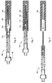
- Figure 1 is an enlarged, partial sectional view of one variation of the pusher-coil assembly showing the coil after uncoupling.
- Figures 2 and 3 show variations of the tip of the socket on the pusher housing.
- Figure 4 is an enlarged view showing the distal end of the pusher housing, the plunger, and the ball on the coil engaged.
- Figure 5 is an enlarged view showing the distal end of the pusher housing, the plunger, and the ball on the coil not engaged.
- Figures 6, 7, and 8 show the procedure for reloading the pusher housing with another embolic coil.
-
- In the drawings, the following convention is used: the proximal end is to the left and the distal end is to the right.
- One variation of the pusher-coil assembly (100) is shown in Figure 1. The coil (102) is depicted to be helical in form, although it may be random or any other suitable form. The coil should be of a size sufficiently small that it may be advanced through a catheter that is appropriately sized for accessing the targeted vascular site. For instance, when accessing a brain aneurysm in a small vessel, an appropriately sized catheter is quite small and very flexible. The coil in such a situation must be small enough to fit through the catheter and out its distal end at the treatment site.
- The coil is desirably made up of a radiopaque, physiologically compatible material. This material may be platinum, gold, tungsten, or alloys of these. A preferred material is a platinum or platinum/tungsten alloy. A number of polymers are also suitable as coil material either alone or in conjunction with metallic markers providing radiopacity, These materials are chosen so that the process of locating the coils within the vessel may be viewed using radiography. However, it is also contemplated that these coils may be made of various other biologically inert polymers or of carbon fiber.
- The size of the coil and its constituent winding will depend upon the use to which the coil will be placed. For occluding peripheral or neural sites, the coils will typically be made of 0.05 to 0.15 mm diameter wire that is wound to have an inner diameter of 0.15 to 1.5 mm with a minimum pitch -- that is to say that the pitch is equal to the diameter of the wire used in the coil. The length of the coil will normally be in the range of 0.5 to 60 cm, preferably 0.5 to 40 cm.
- If desired, the coil may be formed in such a way that the coil is essentially linear as it passes through the catheter and yet assume a randomly oriented relaxed condition after it is released from the distal end of the catheter. A discussion of this variation may be found in U.S. Patent No. 4,994,069.
- Attached to coil (102) is a radially enlarged member, or ball (104). Ball (104) is firmly attached to coil (102) and should not separate during the installation treatment nor thereafter. The remainder of assembly (100) is made up of a pusher housing (106) which is a sheath or tube extending from the proximal end of the assembly (100) to the distal end terminated by a distendible aperture, a socket (108). Socket (108) includes a necked-down portion, a throat (110), which throat has a distendible aperture with a diameter smaller than that of ball (104). The ball (104) is pushed through throat (110) of socket (108) by a plunger head (112). Plunger head (112) easily fits within the aperture of throat (110) so to push ball (104) with its attached coil (102) out into the target site. The socket may have a constant inner diameter instead of the varying diameter shown in Figure 1. Plunger head (112) is pushed via a pusher wire (114). Pusher wire (114) may, as is shown in Figure 1, have a larger diameter at the proximal end of the assembly than at the distal end of the assembly near plunger head (112). In other variations, the diameter of pusher wire (114) may be constant throughout. The pusher wire (114) is desirably actuated by a screw-driven apparatus (116) and (118) in which as a knob (118) is rotated, the pusher wire (114) is advanced axially, distally down through the assembly (100) to push ball (104) out of the aperture (110) of socket (108).
- The length of assembly (100) will be such as to be capable of being advanced entirely through the catheter to place coil (102) at the target site but yet with a sufficient portion of the proximal end of the assembly (100) protruding from the proximal end of the catheter to enable the plunger to be manipulated. For use in peripheral or neural surgeries, the pusher will normally be about 100-200 cm in length, more normally 130-180 cm in length. The diameter of the pusher housing is usually in the range of 0.25 to about 0.90 mm.
- Two variations of the socket are shown in Figures 2 and 3. These variations are optional and are intended to lower the force needed to press ball (104) out through the throat of the socket aperture and yet hold the ball otherwise in a set position. In Figure 2, socket (120) incorporates a number of slots (122) which extend through the wall of the socket and terminate down near the resting place of the ball. This variation allows the ball to be firmly held inside of the socket throat (124) and yet be ejected easily using the plunger apparatus shown in Figure 1. Figure 3 similarly shows side cross-sectional views and end views of a socket which has grooves (128) cut from the distal end of the socket down into the aperture area (130). In each of Figures 2 and 3, the respective throat diameters (124) and (130) are each smaller than the diameter of the ball which is placed through them.
- Assembly (100) is used to place one or more coils at the target site generally using the procedure as follows, As is shown in Figure 4, the coil (102) with its attached ball (104) are included into socket (108) with the ball pushed past socket throat (110). Catheter (132) is inserted and navigated through to the chosen vessel site. The assembly (100) is then included into the catheter lumen to the site to be occluded.
- As indicated previously, conventional catheter insertion and navigational techniques involving guidewires or flow-directed devices may be used to access the site with a catheter. Once the distal end of the catheter is positioned at the site, often by locating its distal end through the use of radiopaque materials of construction and radiography, the catheter is cleared. For instance, if a guidewire has been used to position the catheter, it is withdrawn from the catheter and then the assembly (100) is advanced through the catheter. The assembly (100) is advanced past the distal end of the catheter (132) so that the coil is free of the catheter and with the coil positioned precisely at the desired treatment site. As is shown in Figure 5, plunger wire (114) is advanced to press the ball (104) and its attendant coil (102) into the target site. The entire catheter may then be removed or the assembly (100) may be withdrawn from the catheter lumen to provide for installation of other coils. If additional coils are to be placed at the target site, the procedure is repeated. After the desired number of coils have been placed at the site, the catheter is withdrawn from the vessel.
- Figures 6, 7, and 8 show a method for reloading the assembly (100). Figure 6 shows a coil introducer (150) which includes coil (102) and a ball (104). The coil introducer (150) is cylindrical and adapted to hold a coil (102) and a ball (104) in such a fashion as to allow entry of assembly (100) to one end and allow engagement of throat (110) over ball (104). As is shown in Figure 7, the plunger head (112) is positioned out of the way as the ball is pressed through throat (110) into the position shown there. After the introduction of the ball (104) is complete, assembly (100) is withdrawn from coil introducer (150) as is shown in Figure 8, then placed in a catheter lumen and passed axially along to the target site as described above.
Claims (11)
- A detachable embolic coil (102) comprising a coil having ends and an outer diameter, characterized by an enlarged member (104) fixedly attached to one of said ends, the enlarged member having an outer diameter which is larger than the outer diameter of the coil.
- The coil of claim 1, wherein the enlarged member (104) is a ball.
- The coil of claim 1 or claim 2, wherein the coil material is selected from platinum, gold, tungsten, or alloys of these.
- The coil of claim 1 or claim 2, wherein the coil material is a polymer.
- The coil of claim 1 or claim 2, wherein the coil material is carbon fibre.
- The coil of any one of the preceding claims wherein the coil (102) is helical, random, or straight.
- A pusher-coil assembly (100) for use in occluding a selected site within a vessel, the assembly comprising:(a) a coil (102) of the construction claimed in any one of the preceding claims, wherein the enlarged member (104) is fixedly attached to the coil's proximal end;(b) a pusher housing (106) having a socket (108) at its distal end, said socket having a throat aperture diameter smaller than the diameter of the enlarged member (104) fixedly attached to the coil (102); and(c) a plunger (112) located within the pusher housing (106) that is axially movable relative to the pusher housing and coil (102) from a first position to a second position which pushes the coil and the enlarged member (104) through the socket throat (110) and thus uncouples the coil from the pusher housing.
- The assembly of claim 7, wherein the distal socket end is slotted.
- The assembly of claim 7, wherein the socket throat is grooved.
- The assembly of any one of claims 7 to 9, additionally comprising a pusher wire (114).
- The assembly of claim 10, additionally comprising means for advancing the pusher wire (114) and its plunger head (112).
Priority Applications (2)
| Application Number | Priority Date | Filing Date | Title |
|---|---|---|---|
| EP99102433A EP0914804B1 (en) | 1992-09-22 | 1993-09-03 | Detachable embolic coil assembly |
| DE9320839U DE9320839U1 (en) | 1993-09-03 | 1993-09-03 | Removable embolic coil arrangement |
Applications Claiming Priority (5)
| Application Number | Priority Date | Filing Date | Title |
|---|---|---|---|
| US949095 | 1992-09-22 | ||
| US07/949,095 US5312415A (en) | 1992-09-22 | 1992-09-22 | Assembly for placement of embolic coils using frictional placement |
| US07/975,376 US5350397A (en) | 1992-11-13 | 1992-11-13 | Axially detachable embolic coil assembly |
| US975376 | 1992-11-13 | ||
| PCT/US1993/008346 WO1994006502A2 (en) | 1992-09-22 | 1993-09-03 | Detachable embolic coil assembly |
Related Child Applications (1)
| Application Number | Title | Priority Date | Filing Date |
|---|---|---|---|
| EP99102433A Division EP0914804B1 (en) | 1992-09-22 | 1993-09-03 | Detachable embolic coil assembly |
Publications (3)
| Publication Number | Publication Date |
|---|---|
| EP0617633A1 EP0617633A1 (en) | 1994-10-05 |
| EP0617633A4 EP0617633A4 (en) | 1994-12-07 |
| EP0617633B1 true EP0617633B1 (en) | 1999-12-01 |
Family
ID=27130279
Family Applications (2)
| Application Number | Title | Priority Date | Filing Date |
|---|---|---|---|
| EP93922153A Expired - Lifetime EP0617633B1 (en) | 1992-09-22 | 1993-09-03 | Detachable embolic coil assembly |
| EP99102433A Expired - Lifetime EP0914804B1 (en) | 1992-09-22 | 1993-09-03 | Detachable embolic coil assembly |
Family Applications After (1)
| Application Number | Title | Priority Date | Filing Date |
|---|---|---|---|
| EP99102433A Expired - Lifetime EP0914804B1 (en) | 1992-09-22 | 1993-09-03 | Detachable embolic coil assembly |
Country Status (12)
| Country | Link |
|---|---|
| EP (2) | EP0617633B1 (en) |
| JP (1) | JP2705851B2 (en) |
| AT (1) | ATE187086T1 (en) |
| AU (2) | AU667583B2 (en) |
| CA (1) | CA2123983C (en) |
| DE (2) | DE69332865T2 (en) |
| DK (1) | DK0617633T3 (en) |
| FI (1) | FI942309A (en) |
| IL (1) | IL106947A0 (en) |
| NO (1) | NO941853D0 (en) |
| NZ (1) | NZ256523A (en) |
| WO (1) | WO1994006502A2 (en) |
Families Citing this family (50)
| Publication number | Priority date | Publication date | Assignee | Title |
|---|---|---|---|---|
| DE69332865T2 (en) | 1992-09-22 | 2003-12-04 | Boston Scient Ltd | Arrangement of a detachable embolic coil spring |
| US5743905A (en) * | 1995-07-07 | 1998-04-28 | Target Therapeutics, Inc. | Partially insulated occlusion device |
| DK177010B1 (en) | 1996-09-03 | 2010-11-29 | Cook William Europ | Embolization device for placement in a blood vessel |
| DE19703482A1 (en) * | 1997-01-31 | 1998-08-06 | Ernst Peter Prof Dr M Strecker | Stent |
| US5895410A (en) * | 1997-09-12 | 1999-04-20 | B. Braun Medical, Inc. | Introducer for an expandable vascular occlusion device |
| US5984944A (en) * | 1997-09-12 | 1999-11-16 | B. Braun Medical, Inc. | Introducer for an expandable vascular occlusion device |
| US6203547B1 (en) * | 1997-12-19 | 2001-03-20 | Target Therapeutics, Inc. | Vaso-occlusion apparatus having a manipulable mechanical detachment joint and a method for using the apparatus |
| US6015424A (en) * | 1998-04-28 | 2000-01-18 | Microvention, Inc. | Apparatus and method for vascular embolization |
| NL1009551C2 (en) * | 1998-07-03 | 2000-01-07 | Cordis Europ | Vena cava filter with improvements for controlled ejection. |
| US6277126B1 (en) | 1998-10-05 | 2001-08-21 | Cordis Neurovascular Inc. | Heated vascular occlusion coil development system |
| AU6288799A (en) | 1998-10-09 | 2000-05-01 | Cook Incorporated | Vasoocclusion coil device having a core therein |
| DE69927474T2 (en) | 1999-03-29 | 2006-07-06 | William Cook Europe A/S | A guidewire |
| EP1040842B1 (en) | 1999-03-29 | 2004-05-12 | William Cook Europe ApS | A guidewire |
| US6458137B1 (en) | 1999-05-26 | 2002-10-01 | Cook Incorporated | Assembly for positioning an embolization coil in the vascular system and a method of introducing a detachable embolization coil |
| AU781910B2 (en) | 2000-01-28 | 2005-06-23 | Cook Medical Technologies Llc | Endovascular medical device with plurality of wires |
| US7137993B2 (en) * | 2001-12-03 | 2006-11-21 | Xtent, Inc. | Apparatus and methods for delivery of multiple distributed stents |
| EP1765158B1 (en) | 2004-05-25 | 2017-08-09 | U.S. Endoscopy Group, Inc. | Delivery device |
| ATE448737T1 (en) | 2004-09-22 | 2009-12-15 | Dendron Gmbh | DEVICE FOR IMPLANTING MICROWL COILS |
| US7879064B2 (en) | 2004-09-22 | 2011-02-01 | Micro Therapeutics, Inc. | Medical implant |
| JP2007021101A (en) * | 2005-07-21 | 2007-02-01 | Olympus Biomaterial Corp | Bone prosthetic material and bone prosthetic material unit |
| DE102005053906A1 (en) * | 2005-11-11 | 2007-05-24 | Occlutech Gmbh | Occlusion device e.g. for septal defects in medical technology, has interlaced structure of thin wires or threads whereby holder, on its free end, has top section with eyelet in form of cross bore |
| US7955354B2 (en) | 2005-11-14 | 2011-06-07 | Occlutech Gmbh | Occlusion device and surgical instrument and method for its implantation/explantation |
| US20070123927A1 (en) * | 2005-11-30 | 2007-05-31 | Farnan Robert C | Embolic device delivery system |
| US7942894B2 (en) * | 2006-01-31 | 2011-05-17 | Codman & Shurtleff, Inc. | Embolic device delivery system |
| CA2649702C (en) | 2006-04-17 | 2014-12-09 | Microtherapeutics, Inc. | System and method for mechanically positioning intravascular implants |
| KR20100015520A (en) | 2007-03-13 | 2010-02-12 | 마이크로 테라퓨틱스 인코포레이티드 | An implant including a coil and a stretch-resistant member |
| EP2633823B1 (en) | 2008-04-21 | 2016-06-01 | Covidien LP | Braid-ball embolic devices and delivery systems |
| US9675482B2 (en) | 2008-05-13 | 2017-06-13 | Covidien Lp | Braid implant delivery systems |
| US8333796B2 (en) | 2008-07-15 | 2012-12-18 | Penumbra, Inc. | Embolic coil implant system and implantation method |
| US9814562B2 (en) | 2009-11-09 | 2017-11-14 | Covidien Lp | Interference-relief type delivery detachment systems |
| US8998947B2 (en) | 2010-09-10 | 2015-04-07 | Medina Medical, Inc. | Devices and methods for the treatment of vascular defects |
| EP3354210B1 (en) | 2010-09-10 | 2022-10-26 | Covidien LP | Devices for the treatment of vascular defects |
| US8945171B2 (en) | 2011-09-29 | 2015-02-03 | Covidien Lp | Delivery system for implantable devices |
| US9579104B2 (en) | 2011-11-30 | 2017-02-28 | Covidien Lp | Positioning and detaching implants |
| US9011480B2 (en) | 2012-01-20 | 2015-04-21 | Covidien Lp | Aneurysm treatment coils |
| EP2825242A4 (en) * | 2012-03-15 | 2016-03-30 | Medina Medical Inc | Devices and methods for the treatment of vascular defects |
| US9687245B2 (en) | 2012-03-23 | 2017-06-27 | Covidien Lp | Occlusive devices and methods of use |
| KR102309795B1 (en) | 2012-11-13 | 2021-10-08 | 코비디엔 엘피 | Occlusive devices |
| GB2509952B (en) * | 2013-01-18 | 2015-01-28 | Cook Medical Technologies Llc | Medical device loading and carrier tool |
| EP2967576B1 (en) | 2013-03-15 | 2023-02-15 | Covidien LP | Delivery and detachment mechanisms for vascular implants |
| US9788839B2 (en) | 2014-02-14 | 2017-10-17 | Cook Medical Technologies Llc | Stable screw-type detachment mechanism |
| US9713475B2 (en) | 2014-04-18 | 2017-07-25 | Covidien Lp | Embolic medical devices |
| ES2726910T3 (en) | 2014-07-25 | 2019-10-10 | Incumedx Inc | Covered embolic coils |
| US10478195B2 (en) | 2016-08-04 | 2019-11-19 | Covidien Lp | Devices, systems, and methods for the treatment of vascular defects |
| US10675036B2 (en) | 2017-08-22 | 2020-06-09 | Covidien Lp | Devices, systems, and methods for the treatment of vascular defects |
| WO2019164877A1 (en) | 2018-02-20 | 2019-08-29 | Boston Scientific Scimed, Inc. | Medical device release system |
| US11504816B2 (en) | 2019-11-04 | 2022-11-22 | Covidien Lp | Systems and methods for treating aneurysms |
| CN111870303B (en) * | 2020-08-06 | 2022-06-24 | 聚辉医疗科技(深圳)有限公司 | Embolization device |
| JPWO2023286637A1 (en) * | 2021-07-16 | 2023-01-19 | ||
| WO2023042909A1 (en) * | 2021-09-17 | 2023-03-23 | テルモ株式会社 | Catheter and embolus pre-loaded catheter |
Citations (2)
| Publication number | Priority date | Publication date | Assignee | Title |
|---|---|---|---|---|
| WO1992021400A1 (en) * | 1991-06-07 | 1992-12-10 | Marks Michael P | Retractable-wire catheter device and method |
| WO1993011825A1 (en) * | 1991-12-12 | 1993-06-24 | Target Therapeutics, Inc. | Detachable pusher-vasoocclusive coil assembly with interlocking ball and keyway coupling |
Family Cites Families (15)
| Publication number | Priority date | Publication date | Assignee | Title |
|---|---|---|---|---|
| JPS5313642A (en) * | 1976-03-09 | 1978-02-07 | Dainippon Toryo Co Ltd | Coating composition |
| DE2637690A1 (en) * | 1976-08-21 | 1978-02-23 | Bayer Ag | PROCESS FOR THE PRODUCTION OF Aqueous DISPERSIONS OR SOLUTIONS OF POLYURETHANES AND THEIR USE |
| ZA824176B (en) * | 1981-07-06 | 1983-04-27 | Ici Plc | Polymer dispersions |
| US4512338A (en) * | 1983-01-25 | 1985-04-23 | Balko Alexander B | Process for restoring patency to body vessels |
| US4739768B2 (en) | 1986-06-02 | 1995-10-24 | Target Therapeutics Inc | Catheter for guide-wire tracking |
| JPS63238872A (en) * | 1987-03-25 | 1988-10-04 | テルモ株式会社 | Instrument for securing inner diameter of cavity of tubular organ and catheter equipped therewith |
| US4813934A (en) | 1987-08-07 | 1989-03-21 | Target Therapeutics | Valved catheter device and method |
| US4884579A (en) | 1988-04-18 | 1989-12-05 | Target Therapeutics | Catheter guide wire |
| US4830003A (en) * | 1988-06-17 | 1989-05-16 | Wolff Rodney G | Compressive stent and delivery system |
| US4994069A (en) | 1988-11-02 | 1991-02-19 | Target Therapeutics | Vaso-occlusion coil and method |
| US5122136A (en) * | 1990-03-13 | 1992-06-16 | The Regents Of The University Of California | Endovascular electrolytically detachable guidewire tip for the electroformation of thrombus in arteries, veins, aneurysms, vascular malformations and arteriovenous fistulas |
| EP0528993A1 (en) * | 1990-05-18 | 1993-03-03 | STACK, Richard S. | Intraluminal stent |
| US5109867A (en) * | 1991-04-19 | 1992-05-05 | Target Therapeutics | Extendable guidewire assembly |
| DE69332865T2 (en) | 1992-09-22 | 2003-12-04 | Boston Scient Ltd | Arrangement of a detachable embolic coil spring |
| US5350397A (en) | 1992-11-13 | 1994-09-27 | Target Therapeutics, Inc. | Axially detachable embolic coil assembly |
-
1993
- 1993-09-03 DE DE69332865T patent/DE69332865T2/en not_active Expired - Fee Related
- 1993-09-03 WO PCT/US1993/008346 patent/WO1994006502A2/en active IP Right Grant
- 1993-09-03 EP EP93922153A patent/EP0617633B1/en not_active Expired - Lifetime
- 1993-09-03 AU AU51258/93A patent/AU667583B2/en not_active Ceased
- 1993-09-03 DK DK93922153T patent/DK0617633T3/en active
- 1993-09-03 EP EP99102433A patent/EP0914804B1/en not_active Expired - Lifetime
- 1993-09-03 JP JP6508117A patent/JP2705851B2/en not_active Expired - Lifetime
- 1993-09-03 NZ NZ256523A patent/NZ256523A/en unknown
- 1993-09-03 CA CA002123983A patent/CA2123983C/en not_active Expired - Fee Related
- 1993-09-03 DE DE69327157T patent/DE69327157T2/en not_active Expired - Fee Related
- 1993-09-03 AT AT93922153T patent/ATE187086T1/en active
- 1993-09-08 IL IL106947A patent/IL106947A0/en unknown
-
1994
- 1994-05-18 FI FI942309A patent/FI942309A/en not_active Application Discontinuation
- 1994-05-18 NO NO941853A patent/NO941853D0/en unknown
-
1995
- 1995-03-21 AU AU14985/95A patent/AU672938B2/en not_active Ceased
Patent Citations (3)
| Publication number | Priority date | Publication date | Assignee | Title |
|---|---|---|---|---|
| WO1992021400A1 (en) * | 1991-06-07 | 1992-12-10 | Marks Michael P | Retractable-wire catheter device and method |
| WO1993011825A1 (en) * | 1991-12-12 | 1993-06-24 | Target Therapeutics, Inc. | Detachable pusher-vasoocclusive coil assembly with interlocking ball and keyway coupling |
| US5261916A (en) * | 1991-12-12 | 1993-11-16 | Target Therapeutics | Detachable pusher-vasoocclusive coil assembly with interlocking ball and keyway coupling |
Also Published As
| Publication number | Publication date |
|---|---|
| JP2705851B2 (en) | 1998-01-28 |
| FI942309A0 (en) | 1994-05-18 |
| CA2123983A1 (en) | 1994-03-31 |
| DE69332865T2 (en) | 2003-12-04 |
| CA2123983C (en) | 1996-07-30 |
| EP0914804B1 (en) | 2003-04-09 |
| AU672938B2 (en) | 1996-10-17 |
| ATE187086T1 (en) | 1999-12-15 |
| DK0617633T3 (en) | 2000-04-17 |
| WO1994006502A3 (en) | 1994-04-28 |
| DE69332865D1 (en) | 2003-05-15 |
| IL106947A0 (en) | 1993-12-28 |
| JPH06510936A (en) | 1994-12-08 |
| AU667583B2 (en) | 1996-03-28 |
| AU1498595A (en) | 1995-05-25 |
| EP0617633A4 (en) | 1994-12-07 |
| NO941853L (en) | 1994-06-23 |
| WO1994006502A2 (en) | 1994-03-31 |
| NZ256523A (en) | 1997-04-24 |
| FI942309A (en) | 1994-07-06 |
| DE69327157T2 (en) | 2000-04-06 |
| AU5125893A (en) | 1994-04-12 |
| DE69327157D1 (en) | 2000-01-05 |
| NO941853D0 (en) | 1994-05-18 |
| EP0914804A1 (en) | 1999-05-12 |
| EP0617633A1 (en) | 1994-10-05 |
Similar Documents
| Publication | Publication Date | Title |
|---|---|---|
| EP0617633B1 (en) | Detachable embolic coil assembly | |
| US5350397A (en) | Axially detachable embolic coil assembly | |
| US5800453A (en) | Detachable embolic coil assembly using interlocking hooks and slots | |
| US5925059A (en) | Detachable embolic coil assembly | |
| EP0617632B1 (en) | Detachable embolic coil assembly | |
| US5312415A (en) | Assembly for placement of embolic coils using frictional placement | |
| CA2216613C (en) | Ball joint and introducer for vasoocclusive member | |
| US5250071A (en) | Detachable embolic coil assembly using interlocking clasps and method of use | |
| USRE37117E1 (en) | Detachable embolic coil assembly using interlocking clasps and method of use | |
| EP0616543B1 (en) | Detachable pusher-vasoocclusive coil assembly with interlocking ball and keyway coupling | |
| EP0715532B1 (en) | Detachable microcoil delivery catheter | |
| EP0717961B1 (en) | Implant delivery assembly |
Legal Events
| Date | Code | Title | Description |
|---|---|---|---|
| PUAI | Public reference made under article 153(3) epc to a published international application that has entered the european phase |
Free format text: ORIGINAL CODE: 0009012 |
|
| 17P | Request for examination filed |
Effective date: 19940519 |
|
| AK | Designated contracting states |
Kind code of ref document: A1 Designated state(s): AT BE CH DE DK ES FR GB GR IE IT LI LU MC NL PT SE |
|
| A4 | Supplementary search report drawn up and despatched |
Effective date: 19941024 |
|
| AK | Designated contracting states |
Kind code of ref document: A4 Designated state(s): AT BE CH DE DK ES FR GB GR IE IT LI LU MC NL PT SE |
|
| 17Q | First examination report despatched |
Effective date: 19970723 |
|
| GRAG | Despatch of communication of intention to grant |
Free format text: ORIGINAL CODE: EPIDOS AGRA |
|
| GRAG | Despatch of communication of intention to grant |
Free format text: ORIGINAL CODE: EPIDOS AGRA |
|
| GRAH | Despatch of communication of intention to grant a patent |
Free format text: ORIGINAL CODE: EPIDOS IGRA |
|
| GRAH | Despatch of communication of intention to grant a patent |
Free format text: ORIGINAL CODE: EPIDOS IGRA |
|
| RAP3 | Party data changed (applicant data changed or rights of an application transferred) |
Owner name: TARGET THERAPEUTICS |
|
| GRAA | (expected) grant |
Free format text: ORIGINAL CODE: 0009210 |
|
| AK | Designated contracting states |
Kind code of ref document: B1 Designated state(s): AT BE CH DE DK ES FR GB GR IE IT LI LU MC NL PT SE |
|
| PG25 | Lapsed in a contracting state [announced via postgrant information from national office to epo] |
Ref country code: SE Free format text: THE PATENT HAS BEEN ANNULLED BY A DECISION OF A NATIONAL AUTHORITY Effective date: 19991201 Ref country code: LI Free format text: LAPSE BECAUSE OF FAILURE TO SUBMIT A TRANSLATION OF THE DESCRIPTION OR TO PAY THE FEE WITHIN THE PRESCRIBED TIME-LIMIT Effective date: 19991201 Ref country code: IT Free format text: LAPSE BECAUSE OF FAILURE TO SUBMIT A TRANSLATION OF THE DESCRIPTION OR TO PAY THE FEE WITHIN THE PRESCRIBED TIME-LIMIT;WARNING: LAPSES OF ITALIAN PATENTS WITH EFFECTIVE DATE BEFORE 2007 MAY HAVE OCCURRED AT ANY TIME BEFORE 2007. THE CORRECT EFFECTIVE DATE MAY BE DIFFERENT FROM THE ONE RECORDED. Effective date: 19991201 Ref country code: GR Free format text: LAPSE BECAUSE OF NON-PAYMENT OF DUE FEES Effective date: 19991201 Ref country code: ES Free format text: THE PATENT HAS BEEN ANNULLED BY A DECISION OF A NATIONAL AUTHORITY Effective date: 19991201 Ref country code: CH Free format text: LAPSE BECAUSE OF FAILURE TO SUBMIT A TRANSLATION OF THE DESCRIPTION OR TO PAY THE FEE WITHIN THE PRESCRIBED TIME-LIMIT Effective date: 19991201 Ref country code: BE Free format text: LAPSE BECAUSE OF FAILURE TO SUBMIT A TRANSLATION OF THE DESCRIPTION OR TO PAY THE FEE WITHIN THE PRESCRIBED TIME-LIMIT Effective date: 19991201 Ref country code: AT Free format text: LAPSE BECAUSE OF FAILURE TO SUBMIT A TRANSLATION OF THE DESCRIPTION OR TO PAY THE FEE WITHIN THE PRESCRIBED TIME-LIMIT Effective date: 19991201 |
|
| REF | Corresponds to: |
Ref document number: 187086 Country of ref document: AT Date of ref document: 19991215 Kind code of ref document: T |
|
| REG | Reference to a national code |
Ref country code: CH Ref legal event code: EP |
|
| REF | Corresponds to: |
Ref document number: 69327157 Country of ref document: DE Date of ref document: 20000105 |
|
| REG | Reference to a national code |
Ref country code: IE Ref legal event code: FG4D |
|
| PG25 | Lapsed in a contracting state [announced via postgrant information from national office to epo] |
Ref country code: PT Free format text: LAPSE BECAUSE OF FAILURE TO SUBMIT A TRANSLATION OF THE DESCRIPTION OR TO PAY THE FEE WITHIN THE PRESCRIBED TIME-LIMIT Effective date: 20000302 |
|
| REG | Reference to a national code |
Ref country code: DK Ref legal event code: T3 |
|
| REG | Reference to a national code |
Ref country code: CH Ref legal event code: PL |
|
| PG25 | Lapsed in a contracting state [announced via postgrant information from national office to epo] |
Ref country code: LU Free format text: LAPSE BECAUSE OF NON-PAYMENT OF DUE FEES Effective date: 20000903 |
|
| PLBE | No opposition filed within time limit |
Free format text: ORIGINAL CODE: 0009261 |
|
| STAA | Information on the status of an ep patent application or granted ep patent |
Free format text: STATUS: NO OPPOSITION FILED WITHIN TIME LIMIT |
|
| PG25 | Lapsed in a contracting state [announced via postgrant information from national office to epo] |
Ref country code: MC Free format text: THE PATENT HAS BEEN ANNULLED BY A DECISION OF A NATIONAL AUTHORITY Effective date: 20000930 |
|
| 26N | No opposition filed | ||
| REG | Reference to a national code |
Ref country code: GB Ref legal event code: IF02 |
|
| PGFP | Annual fee paid to national office [announced via postgrant information from national office to epo] |
Ref country code: FR Payment date: 20060906 Year of fee payment: 14 |
|
| PGFP | Annual fee paid to national office [announced via postgrant information from national office to epo] |
Ref country code: GB Payment date: 20070809 Year of fee payment: 15 |
|
| PGFP | Annual fee paid to national office [announced via postgrant information from national office to epo] |
Ref country code: NL Payment date: 20070806 Year of fee payment: 15 |
|
| PGFP | Annual fee paid to national office [announced via postgrant information from national office to epo] |
Ref country code: DK Payment date: 20060807 Year of fee payment: 14 |
|
| REG | Reference to a national code |
Ref country code: DK Ref legal event code: EBP |
|
| REG | Reference to a national code |
Ref country code: FR Ref legal event code: ST Effective date: 20080531 |
|
| PG25 | Lapsed in a contracting state [announced via postgrant information from national office to epo] |
Ref country code: FR Free format text: LAPSE BECAUSE OF NON-PAYMENT OF DUE FEES Effective date: 20071001 Ref country code: DK Free format text: LAPSE BECAUSE OF NON-PAYMENT OF DUE FEES Effective date: 20071001 |
|
| PGFP | Annual fee paid to national office [announced via postgrant information from national office to epo] |
Ref country code: IE Payment date: 20080718 Year of fee payment: 16 |
|
| PGFP | Annual fee paid to national office [announced via postgrant information from national office to epo] |
Ref country code: DE Payment date: 20080930 Year of fee payment: 16 |
|
| GBPC | Gb: european patent ceased through non-payment of renewal fee |
Effective date: 20080903 |
|
| PG25 | Lapsed in a contracting state [announced via postgrant information from national office to epo] |
Ref country code: NL Free format text: LAPSE BECAUSE OF NON-PAYMENT OF DUE FEES Effective date: 20090401 |
|
| NLV4 | Nl: lapsed or anulled due to non-payment of the annual fee |
Effective date: 20090401 |
|
| PG25 | Lapsed in a contracting state [announced via postgrant information from national office to epo] |
Ref country code: GB Free format text: LAPSE BECAUSE OF NON-PAYMENT OF DUE FEES Effective date: 20080903 |
|
| REG | Reference to a national code |
Ref country code: IE Ref legal event code: MM4A |
|
| PG25 | Lapsed in a contracting state [announced via postgrant information from national office to epo] |
Ref country code: IE Free format text: LAPSE BECAUSE OF NON-PAYMENT OF DUE FEES Effective date: 20090903 Ref country code: DE Free format text: LAPSE BECAUSE OF NON-PAYMENT OF DUE FEES Effective date: 20100401 |