EP0617342A2 - Photoreceptor belt seam detection and process control - Google Patents
Photoreceptor belt seam detection and process control Download PDFInfo
- Publication number
- EP0617342A2 EP0617342A2 EP94302026A EP94302026A EP0617342A2 EP 0617342 A2 EP0617342 A2 EP 0617342A2 EP 94302026 A EP94302026 A EP 94302026A EP 94302026 A EP94302026 A EP 94302026A EP 0617342 A2 EP0617342 A2 EP 0617342A2
- Authority
- EP
- European Patent Office
- Prior art keywords
- belt
- seam
- imager
- sensor
- image
- Prior art date
- Legal status (The legal status is an assumption and is not a legal conclusion. Google has not performed a legal analysis and makes no representation as to the accuracy of the status listed.)
- Granted
Links
Images


Classifications
-
- G—PHYSICS
- G03—PHOTOGRAPHY; CINEMATOGRAPHY; ANALOGOUS TECHNIQUES USING WAVES OTHER THAN OPTICAL WAVES; ELECTROGRAPHY; HOLOGRAPHY
- G03G—ELECTROGRAPHY; ELECTROPHOTOGRAPHY; MAGNETOGRAPHY
- G03G15/00—Apparatus for electrographic processes using a charge pattern
- G03G15/01—Apparatus for electrographic processes using a charge pattern for producing multicoloured copies
- G03G15/0142—Structure of complete machines
- G03G15/0147—Structure of complete machines using a single reusable electrographic recording member
- G03G15/0152—Structure of complete machines using a single reusable electrographic recording member onto which the monocolour toner images are superposed before common transfer from the recording member
-
- G—PHYSICS
- G03—PHOTOGRAPHY; CINEMATOGRAPHY; ANALOGOUS TECHNIQUES USING WAVES OTHER THAN OPTICAL WAVES; ELECTROGRAPHY; HOLOGRAPHY
- G03G—ELECTROGRAPHY; ELECTROPHOTOGRAPHY; MAGNETOGRAPHY
- G03G15/00—Apparatus for electrographic processes using a charge pattern
- G03G15/01—Apparatus for electrographic processes using a charge pattern for producing multicoloured copies
- G03G15/0105—Details of unit
- G03G15/011—Details of unit for exposing
-
- G—PHYSICS
- G03—PHOTOGRAPHY; CINEMATOGRAPHY; ANALOGOUS TECHNIQUES USING WAVES OTHER THAN OPTICAL WAVES; ELECTROGRAPHY; HOLOGRAPHY
- G03G—ELECTROGRAPHY; ELECTROPHOTOGRAPHY; MAGNETOGRAPHY
- G03G15/00—Apparatus for electrographic processes using a charge pattern
- G03G15/01—Apparatus for electrographic processes using a charge pattern for producing multicoloured copies
- G03G15/0142—Structure of complete machines
- G03G15/0147—Structure of complete machines using a single reusable electrographic recording member
- G03G15/0152—Structure of complete machines using a single reusable electrographic recording member onto which the monocolour toner images are superposed before common transfer from the recording member
- G03G15/0163—Structure of complete machines using a single reusable electrographic recording member onto which the monocolour toner images are superposed before common transfer from the recording member primary transfer to the final recording medium
-
- G—PHYSICS
- G03—PHOTOGRAPHY; CINEMATOGRAPHY; ANALOGOUS TECHNIQUES USING WAVES OTHER THAN OPTICAL WAVES; ELECTROGRAPHY; HOLOGRAPHY
- G03G—ELECTROGRAPHY; ELECTROPHOTOGRAPHY; MAGNETOGRAPHY
- G03G21/00—Arrangements not provided for by groups G03G13/00 - G03G19/00, e.g. cleaning, elimination of residual charge
- G03G21/14—Electronic sequencing control
- G03G21/145—Electronic sequencing control wherein control pulses are generated by the mechanical movement of parts of the machine, e.g. the photoconductor
-
- G—PHYSICS
- G03—PHOTOGRAPHY; CINEMATOGRAPHY; ANALOGOUS TECHNIQUES USING WAVES OTHER THAN OPTICAL WAVES; ELECTROGRAPHY; HOLOGRAPHY
- G03G—ELECTROGRAPHY; ELECTROPHOTOGRAPHY; MAGNETOGRAPHY
- G03G2215/00—Apparatus for electrophotographic processes
- G03G2215/01—Apparatus for electrophotographic processes for producing multicoloured copies
- G03G2215/0151—Apparatus for electrophotographic processes for producing multicoloured copies characterised by the technical problem
- G03G2215/0158—Colour registration
- G03G2215/0161—Generation of registration marks
-
- G—PHYSICS
- G03—PHOTOGRAPHY; CINEMATOGRAPHY; ANALOGOUS TECHNIQUES USING WAVES OTHER THAN OPTICAL WAVES; ELECTROGRAPHY; HOLOGRAPHY
- G03G—ELECTROGRAPHY; ELECTROPHOTOGRAPHY; MAGNETOGRAPHY
- G03G2215/00—Apparatus for electrophotographic processes
- G03G2215/01—Apparatus for electrophotographic processes for producing multicoloured copies
- G03G2215/0167—Apparatus for electrophotographic processes for producing multicoloured copies single electrographic recording member
- G03G2215/017—Apparatus for electrophotographic processes for producing multicoloured copies single electrographic recording member single rotation of recording member to produce multicoloured copy
Definitions
- the invention relates generally to an electrophotographic printing machine having a seamed, web-type photoreceptor suitable for the exposure of one or more document latent images on the surface thereof, and, more particularly, to a method and apparatus for detecting the belt seam and for generating a signal useful for process control and machine timing.
- the features of the present invention may be used in the printing arts, and, more particularly, in electrophotographic printing.
- a photoconductive surface is charged to a substantially uniform potential.
- the photoconductive surface is then image-wise exposed to record an electrostatic latent image corresponding to the informational areas of an original document being reproduced.
- a developer material is transported into contact with the electrostatic latent image.
- Toner particles are attracted from the carrier granules of the developer material onto the latent image.
- the resultant toner powder image is then transferred from the photoconductive surface to a copy sheet and permanently affixed thereto.
- a photoreceptor belt is preferred for the photosensitive member.
- Belts have the capacity to form a plurality of images in a plurality of image frames available on the photoreceptor surface during a single pass or revolution of the belt.
- belts are formed by a process which leaves a seam extending across the belt width. The seam presents a discontinuity in the photoreceptor surface.
- the photoreceptor belt is moved at a predefined velocity, and the rate of travel of the advancing copy sheet is controlled so as to regulate the exposure and transfer operations in accordance with the position of the advancing sheet.
- a number of techniques have been developed to overcome this problem.
- a typical solution is to cut a hole into the belt at a predetermined displacement from the belt seam and detect the passage of the hole with a photosensor whose output is then used to control the various xerographic stations and/or the photoreceptor speed so that the latent image is not projected across the belt seam.
- This type of scan seam hole sensing is disclosed, for example, in US-A-5,101,232 and 4,922,305.
- notches formed in the belt edge at known distances from the belt seam are detected by sensors which generate outputs used for timing and control purposes. See, for example, US-A-4,847,660.
- the two prior art techniques require an additional process step in the belt manufacture to form the hole or notch. Further, holes created in the belt produce a stress concentration which weakens the structural integrity of the belt leading to cracking or tearing failures near the hole or aperture.
- One object of the present invention is to provide a method of detecting the belt seam, which method obviates the need to punch holes in the belt thereby improving belt reliability.
- the present invention provides a method of detecting a seam in a belt, a reproduction machine and an imaging system as claimed in the appended claims.
- light from the ends of a linear light array which is selectively controlled to expose a photoreceptor surface is used to illuminate the belt seam of the photoreceptor belt passing therebeneath.
- a detector is located on the opposite side of the belt in optical alignment with the linear array ends. The light detected by the sensor when the seam is illuminated is at a different level from the light sensed through the belt in non-seamed areas. The signal that is generated when a seam is detected is used for the conventional purposes of calibrating machine operation to ensure that images will not be exposed over the seam.
- a sensor associated with detecting registration holes or marks on the belt is used for the additional purpose of detecting passage of the belt seam.
- the present invention relates to an improved reproduction machine of the type having a light transmissive photoreceptor belt mounted for movement substantially in a predetermined reference direction, said belt having a seam extending across the width thereof, wherein the improvement comprises: an imager opposed from one surface of the belt for sequentially exposing portions of the belt surface to form an image thereof, and at least one light sensitive sensor opposed from the other surface of the belt for sensing passage of the seam between the imager and the sensor, and for generating an output signal representative of said seam detection.
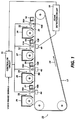
- Figure 1 shows a printing system having four exposure stations 10, 12, 14, 16, each station including an LED print bar 10A, 12A, 14A, 16A.
- Figure 2 shows a top view of the system of Figure 1, absent some of the xerographic stations, for ease of description.
- each print bar is selectively addressed by video image signals processed through controller circuit 15, to produce a modulated output which is coupled through a gradient index lens array 10B, 12B, 14B, 16B, onto the surface of previously charged semi-transparent photoreceptor belt 17.
- Photoreceptor belt 17 is formed by a process resulting in a seam 98 extending across the width thereof.
- Belt 10 is semi-transparent and, preferably, is made from a photoconductive material coated on a ground layer, which, in turn, is coated on anti-curl backing layer.
- the photoconductive material is made from a transport layer coated on a generator layer.
- the interface layer is coated on the ground layer.
- the transport layer contains small molecules of di-m-tolydiphenyldiphenylbithenyldiamine dispersed in a polycarbonate.
- the generation layer is made from trigonal selenium.
- the grounding layer is made from a titanium coated mylar.
- the ground layer is very thin and allows a portion of the incident light to pass therethrough.
- Other suitable photoconductive materials, ground layers, and anti-curl backing layers may also be employed.
- Belt 17 moves in the direction of arrow 24 to advance successive portions of the photoconductive surface sequentially through the various processing stations (not shown)
- the video image signals to the print bar may be computer generated color images or digital signals representing a document which has been scanned with a conventional RIS scanner.
- Exposure stations 12A, 14A, 16A also include sensor circuits 40, 42, 44, for purposes described below.
- the length of belt 17 is designed to accept an integral number of full page image frames; e.g. I1-I4, represented by dashed lines. Upstream of each exposure station are charge devices 18, 19, 20, 21, ( Figure 1) which place a predetermined electrical charge on the surface of belt 17. As the belt moves in the direction of arrow 24, each image frame moves past each of the print bars, with each bar providing its own exposure pattern, in response to the video image signal input.
- the exposure pattern begins when the leading edge of an image frame reaches a transverse start-of-exposure line, represented in image frame I1 by a line 23.
- the exposure pattern is formed of a plurality of closely spaced transverse scan lines. Downstream from each exposure station, a development system 26, 27, 28, 29, develops a latent image of the last exposure without disturbing previously developed images. A fully developed color image is then transferred at transfer station 33, by means not shown, to an output sheet. Further details of the operation of xerographic stations in a multiple exposure single pass system are disclosed in US-A-4,660,059 and 4,833,503, whose contents are hereby incorporated by reference.
- a target 30 is formed by adding a bit map data input to print bar 10A, via controller circuit 15, to expose a line image which is subsequently developed as target line 30 shown in Figure 2.
- This line is formed in a non-image, interdocument area which precedes the leading edge (line of exposure 23) of image frame I1 by several scan lines.
- a portion of belt 17 passes the charging station 18 which places the required charge on the surface of belt 10.
- the uniformly charged, photoconductive surface is exposed by print bar 10A which causes the charged portion of the belt to be discharged, first to form a latent image of the line mark and then a first black image, the image formed by creating a series of horizontal lines, each line having a certain number of pixels per inch at development station 26.
- a magnetic brush system advances the appropriate color development material, here black, into contact with the latent electrostatic image.
- the black developed latent image and the developed target line 30 continue to advance in the direction of arrow 24.
- Charge station 19 recharges the photoconductive surface of belt 17, including the black developed frame.
- a portion of print bar 12A is energized to provide a light output used to detect the passage of mark 30.
- Sensor 40 is located in a fixed position, relative to the underside of belt 17. The lighted portion of bar 12A faces sensor 40.
- Sensor 40 in a preferred embodiment, is a small PIN photodiode, which is sensitive to the wavelength of print bar 12A.
- the arrival of mark 30 is detected by turning on the print bar 12A to a level such that light can be detected by sensor 40 through the semi-transparent belt 17 for a window of time when the timing mark line is expected.
- the output of sensor 40 is sent to control circuit 15 which controls the operation of the print bar so as to initiate the start of scan exposure line for each image frame.
- the seam 98 is formed as part of the process of making the belt 17. With installation of each individual belt, an initial calibration is performed which identifies the seam location and sets the image frames to be outside of the seam. While the initial location of the seam vis a vis the exposure frames I1-I4 is known, over operation changes in the belt speed may move the images formed to a location which could intrude upon the seam, resulting in a defect to output copies.
- one of the sensors 40, 42, 44 could also be used to detect the passage in position of seam 98.
- sensor 40 besides detecting mark 30, can also serve a second function and can detect passage of the belt seam as the belt, once each revolution, moves the seam therepast.
- FIG. 1 An output signal distinct from the signal generated when the target is sensed will be generated.
- the sensor 40 detects the passage of seam 98 and the output waveform, which contains information on seam width and density, is sent to circuit 50.
- Figure 3 shows three representative output waveforms of sensor 40, waveform A being the output when neither a mark nor seam is detected; waveform B being the signal when a mark is detected and waveform C being the waveform signal output when the seam is detected.
- the seam output is sufficiently different in magnitude and shape from the other outputs so as to be easily identified in a discrimination circuit 50, which sends an appropriate signal to controller circuit 15.
- Circuit 15 uses the signal to control the operation of the imagers to ensure that an image is not formed across the seam.
- Seam detection circuit 50 can sense both signal magnitude and signal duration.
- the magnitude of the toner mark signal for this example, is approximately 10%, or less, of the full transmission magnitude.
- the seam signal is shown as about 50% of the full transmission magnitude and with a greater width than the toner signal.
- the signal duration of the toner mark will be less than 1 milli sec (based on, for example, a process velocity of 300 mm/sec, and width of the toner mark of 0.2 mm) while the seam signal duration can be greater than 10 milli sec. It is understood that the seam density and width may have other characteristics relative to the toner mark, for example, greater density and a shorter width.
- Circuit 50 compares the input signal and identifies it as the previously stored seam signal. Circuit 50 then digitizes the input signal from the sensor and produces an output signal pulse which is at the center of the detected seam signal.
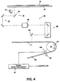
- FIG. 4 shows a light lens scanning system 70 wherein a document 72 placed on platen 74 is scanned by a scan assembly 76.
- Scan assembly 76 comprises a lamp 77, full rate mirror 78 and a one half rate mirror 79.
- the reflected line images are projected by lens 80 and folded by mirror assembly 82 and belt mirror 84 to form the latent image of the document on belt 17.
- the latent image is developed, transferred and fused by conventional xerographic techniques.
- Seam 98 on belt 17 is detected when it passes between a dedicated lamp source 60 and sensor 140.
- Output signals from sensor 140 are sent to seam detection circuit 50 where belt signals are identified as such and sent to the controller.
Abstract
Description
- The invention relates generally to an electrophotographic printing machine having a seamed, web-type photoreceptor suitable for the exposure of one or more document latent images on the surface thereof, and, more particularly, to a method and apparatus for detecting the belt seam and for generating a signal useful for process control and machine timing.
- The features of the present invention may be used in the printing arts, and, more particularly, in electrophotographic printing. In the process of electrophotographic printing, a photoconductive surface is charged to a substantially uniform potential. The photoconductive surface is then image-wise exposed to record an electrostatic latent image corresponding to the informational areas of an original document being reproduced. Thereafter, a developer material is transported into contact with the electrostatic latent image. Toner particles are attracted from the carrier granules of the developer material onto the latent image. The resultant toner powder image is then transferred from the photoconductive surface to a copy sheet and permanently affixed thereto. The foregoing description generally describes a typical single color electrophotographic copying machine.
- For many high speed copier applications a photoreceptor belt is preferred for the photosensitive member. Belts have the capacity to form a plurality of images in a plurality of image frames available on the photoreceptor surface during a single pass or revolution of the belt. As is known in the art, belts are formed by a process which leaves a seam extending across the belt width. The seam presents a discontinuity in the photoreceptor surface. In operation, the photoreceptor belt is moved at a predefined velocity, and the rate of travel of the advancing copy sheet is controlled so as to regulate the exposure and transfer operations in accordance with the position of the advancing sheet. Minor variations in the speed of the belt drive motor, due, for example, to variations in the power line voltage, result in a variation of the position of latent images on the photoreceptor. These variations are cumulative in nature and must be corrected to assure that the latent images are exposed at generally the same positions on the photoreceptor each time. If not corrected, the cumulative variation would eventually cause one or more of the exposed latent image areas to encroach on the photoreceptor seam, subsequently resulting in an unacceptable copy.
- A number of techniques have been developed to overcome this problem. A typical solution is to cut a hole into the belt at a predetermined displacement from the belt seam and detect the passage of the hole with a photosensor whose output is then used to control the various xerographic stations and/or the photoreceptor speed so that the latent image is not projected across the belt seam. This type of scan seam hole sensing is disclosed, for example, in US-A-5,101,232 and 4,922,305.
- Alternatively, notches formed in the belt edge at known distances from the belt seam are detected by sensors which generate outputs used for timing and control purposes. See, for example, US-A-4,847,660.
- The two prior art techniques require an additional process step in the belt manufacture to form the hole or notch. Further, holes created in the belt produce a stress concentration which weakens the structural integrity of the belt leading to cracking or tearing failures near the hole or aperture.
- One object of the present invention is to provide a method of detecting the belt seam, which method obviates the need to punch holes in the belt thereby improving belt reliability.
- Accordingly, the present invention provides a method of detecting a seam in a belt, a reproduction machine and an imaging system as claimed in the appended claims.
- According to one embodiment of the present invention, and in a preferred embodiment of a color copier, light from the ends of a linear light array which is selectively controlled to expose a photoreceptor surface, is used to illuminate the belt seam of the photoreceptor belt passing therebeneath. For systems having light transmissive belts, a detector is located on the opposite side of the belt in optical alignment with the linear array ends. The light detected by the sensor when the seam is illuminated is at a different level from the light sensed through the belt in non-seamed areas. The signal that is generated when a seam is detected is used for the conventional purposes of calibrating machine operation to ensure that images will not be exposed over the seam.
- According to another embodiment of the present invention, and in a color system wherein a plurality of color images are sequentially formed on the belt surface, developed and transferred to a copy sheet, a sensor associated with detecting registration holes or marks on the belt is used for the additional purpose of detecting passage of the belt seam.
- In a further embodiment, the present invention relates to an improved reproduction machine of the type having a light transmissive photoreceptor belt mounted for movement substantially in a predetermined reference direction, said belt having a seam extending across the width thereof, wherein the improvement comprises:
an imager opposed from one surface of the belt for sequentially exposing portions of the belt surface to form an image thereof, and
at least one light sensitive sensor opposed from the other surface of the belt for sensing passage of the seam between the imager and the sensor, and for generating an output signal representative of said seam detection. - The present invention will be described further by way of examples with reference to, and as illustrated in, the accompanying drawings:-
- Figure 1 is a side view of a single pass LED image bar printer incorporating the improved seamed detection circuitry of the present invention,
- Figure 2 is a top view of the printer of Figure 1 omitting the xerographic stations excepting the exposure station,
- Figure 3 shows outputs from a sensor which can be differentiated to indicate detection of the belt seam, and
- Figure 4 is a side view of a light lens scanning system incorporating the seam detection circuitry of the present invention.
- Figure 1 shows a printing system having four
exposure stations LED print bar controller circuit 15, to produce a modulated output which is coupled through a gradientindex lens array semi-transparent photoreceptor belt 17. -
Photoreceptor belt 17 is formed by a process resulting in aseam 98 extending across the width thereof.Belt 10 is semi-transparent and, preferably, is made from a photoconductive material coated on a ground layer, which, in turn, is coated on anti-curl backing layer. The photoconductive material is made from a transport layer coated on a generator layer. The interface layer is coated on the ground layer. The transport layer contains small molecules of di-m-tolydiphenyldiphenylbithenyldiamine dispersed in a polycarbonate. The generation layer is made from trigonal selenium. The grounding layer is made from a titanium coated mylar. The ground layer is very thin and allows a portion of the incident light to pass therethrough. Other suitable photoconductive materials, ground layers, and anti-curl backing layers may also be employed.Belt 17 moves in the direction ofarrow 24 to advance successive portions of the photoconductive surface sequentially through the various processing stations (not shown) disposed about the path of movement thereof. - The video image signals to the print bar may be computer generated color images or digital signals representing a document which has been scanned with a conventional RIS scanner.
Exposure stations sensor circuits belt 17 is designed to accept an integral number of full page image frames; e.g. I₁-I₄, represented by dashed lines. Upstream of each exposure station arecharge devices belt 17. As the belt moves in the direction ofarrow 24, each image frame moves past each of the print bars, with each bar providing its own exposure pattern, in response to the video image signal input. The exposure pattern begins when the leading edge of an image frame reaches a transverse start-of-exposure line, represented in image frame I₁ by aline 23. The exposure pattern is formed of a plurality of closely spaced transverse scan lines. Downstream from each exposure station, adevelopment system transfer station 33, by means not shown, to an output sheet. Further details of the operation of xerographic stations in a multiple exposure single pass system are disclosed in US-A-4,660,059 and 4,833,503, whose contents are hereby incorporated by reference. - With such a system as that disclosed in Figures 1 and 2, following the first image exposure, successive color images are precisely aligned (registered) in the process and cross-process directions so that the start of exposure line for each frame is registered with previous start of exposure lines.
- There are a number of prior art techniques for correcting the registration. For the system shown, a
target 30 is formed by adding a bit map data input toprint bar 10A, viacontroller circuit 15, to expose a line image which is subsequently developed astarget line 30 shown in Figure 2. This line is formed in a non-image, interdocument area which precedes the leading edge (line of exposure 23) of image frame I₁ by several scan lines. - In a description of formation of a full color image;initially, a portion of
belt 17 passes the chargingstation 18 which places the required charge on the surface ofbelt 10. As the belt advances intoimaging station 10, the uniformly charged, photoconductive surface is exposed byprint bar 10A which causes the charged portion of the belt to be discharged, first to form a latent image of the line mark and then a first black image, the image formed by creating a series of horizontal lines, each line having a certain number of pixels per inch atdevelopment station 26. Atdevelopment station 26, a magnetic brush system, for example, advances the appropriate color development material, here black, into contact with the latent electrostatic image. The black developed latent image and thedeveloped target line 30 continue to advance in the direction ofarrow 24. -
Charge station 19 recharges the photoconductive surface ofbelt 17, including the black developed frame. Atsecond imaging station 12, a portion ofprint bar 12A is energized to provide a light output used to detect the passage ofmark 30.Sensor 40 is located in a fixed position, relative to the underside ofbelt 17. The lighted portion ofbar 12A facessensor 40.Sensor 40, in a preferred embodiment, is a small PIN photodiode, which is sensitive to the wavelength ofprint bar 12A. The arrival ofmark 30 is detected by turning on theprint bar 12A to a level such that light can be detected bysensor 40 through thesemi-transparent belt 17 for a window of time when the timing mark line is expected. The output ofsensor 40 is sent to controlcircuit 15 which controls the operation of the print bar so as to initiate the start of scan exposure line for each image frame. - As referenced above, the
seam 98 is formed as part of the process of making thebelt 17. With installation of each individual belt, an initial calibration is performed which identifies the seam location and sets the image frames to be outside of the seam. While the initial location of the seam vis a vis the exposure frames I₁-I₄ is known, over operation changes in the belt speed may move the images formed to a location which could intrude upon the seam, resulting in a defect to output copies. According to an embodiment of the invention, one of thesensors seam 98. For example,sensor 40, besides detectingmark 30, can also serve a second function and can detect passage of the belt seam as the belt, once each revolution, moves the seam therepast. An output signal distinct from the signal generated when the target is sensed will be generated. During initial calibration, thesensor 40 detects the passage ofseam 98 and the output waveform, which contains information on seam width and density, is sent tocircuit 50. Figure 3 shows three representative output waveforms ofsensor 40, waveform A being the output when neither a mark nor seam is detected; waveform B being the signal when a mark is detected and waveform C being the waveform signal output when the seam is detected. As is evident, the seam output is sufficiently different in magnitude and shape from the other outputs so as to be easily identified in adiscrimination circuit 50, which sends an appropriate signal tocontroller circuit 15.Circuit 15 uses the signal to control the operation of the imagers to ensure that an image is not formed across the seam.Seam detection circuit 50 can sense both signal magnitude and signal duration. The magnitude of the toner mark signal, for this example, is approximately 10%, or less, of the full transmission magnitude. The seam signal is shown as about 50% of the full transmission magnitude and with a greater width than the toner signal. The signal duration of the toner mark will be less than 1 milli sec (based on, for example, a process velocity of 300 mm/sec, and width of the toner mark of 0.2 mm) while the seam signal duration can be greater than 10 milli sec. It is understood that the seam density and width may have other characteristics relative to the toner mark, for example, greater density and a shorter width.Circuit 50 compares the input signal and identifies it as the previously stored seam signal.Circuit 50 then digitizes the input signal from the sensor and produces an output signal pulse which is at the center of the detected seam signal. - Although the invention has been described in the context of an LED print bar imager as the light source, it is understood that other imagers may be used such as, for example, a gas discharge or LCD shutter image bar, or a Raster Output Scanner (ROS). Further, for some systems, a dedicated light source may be used in conjunction with a sensor dedicated solely to viewing the seam passing one per revolution and generating a single pulse. The light source would be energized for a time interval during which seam passage is assured. Figure 4 shows a light
lens scanning system 70 wherein adocument 72 placed onplaten 74 is scanned by ascan assembly 76.Scan assembly 76 comprises alamp 77,full rate mirror 78 and a onehalf rate mirror 79. The reflected line images are projected bylens 80 and folded bymirror assembly 82 andbelt mirror 84 to form the latent image of the document onbelt 17. The latent image is developed, transferred and fused by conventional xerographic techniques.Seam 98 onbelt 17 is detected when it passes between adedicated lamp source 60 andsensor 140. Output signals fromsensor 140 are sent toseam detection circuit 50 where belt signals are identified as such and sent to the controller.
Claims (7)
- A reproduction machine of the type having a light transmissive photoreceptor belt (17) mounted for movement substantially in a predetermined reference direction (24), said belt (17) having a seam (98) extending across the width thereof, characterised by
an imager (12A) opposed from one surface of the belt (17) for sequentially exposing portions of the belt surface to form an image thereof, and
at least one light sensitive sensor (40) opposed from the other surface of the belt (17) for sensing passage of the seam (98) between the imager (12A) and the sensor (40), and for generating an output signal representative of said seam (98) detection. - A machine as claimed in claim 1, further characterised by control means (50) responsive to said sensor output signal for adjusting said imager (12A) to expose said belt surface only in non-seam areas.
- A method of detecting a seam (98) on a light transmissive photoreceptor belt (17) including
positioning a light source (60) opposed from one surface of the belt for illuminating a portion of the belt (17) outside of an image-forming area,
positioning a light sensitive sensor (140) opposed from the other surface of the belt (17) for sensing the passing of the seam (98) between the light source and the sensor,
moving the belt so as to periodically move said seam between said light source (60) and said sensor (140), and
generating a signal upon detection of the belt seam (98). - A method as claimed in claim 3, wherein said light source (60) is stationary.
- An imaging system for forming multiple image exposure frames on a light transmissive photoreceptor belt (17) having a seam (98) extending across the width thereof, said system including:
a photoreceptor belt (17) adapted to accommodate the formation of an integral number of image exposure frames (I₁-I₄), said belt (17) having at least one registration mark (30) associated with at least one image frame (I₁), said mark (30) located outside of the exposure frame (I₁),
at least one imager (12A) associated with the formation of one of said image exposure frames (I₁-I₄), each imager (12A) having a first portion of light emitting pixels which are selectively activated to form said image exposure frames and a second portion of light emitting pixels outside of said exposure area which are activated for imager registration and seam detection purposes,
detecting means (40) associated with said second portion and on the opposite side of the belt, said detecting means (40) generating a first set of output signals when said registration marks (30) pass between said second portion and the detecting means (40) and a second set of output signals when said belt seam passes between the second portion and the detecting means (40), and
control means (15) for comparing said output signals and generating at least a seam identification signal upon detecting a second output signal associated with passage of the belt seam (98). - An imaging station as claimed in claim 5, wherein said first portion of the imager (12A) is a central portion of light emitting pixels and said second portion of the imager (12A) is an end portion of light emitting pixels.
- An imaging station as claimed in claim 5 or claim 6, wherein the imager is a LED print bar.
Applications Claiming Priority (2)
| Application Number | Priority Date | Filing Date | Title |
|---|---|---|---|
| US35869 | 1993-03-23 | ||
| US08/035,869 US5291245A (en) | 1993-03-23 | 1993-03-23 | Photoreceptor belt seam detection and process control |
Publications (3)
| Publication Number | Publication Date |
|---|---|
| EP0617342A2 true EP0617342A2 (en) | 1994-09-28 |
| EP0617342A3 EP0617342A3 (en) | 1995-04-05 |
| EP0617342B1 EP0617342B1 (en) | 1998-07-08 |
Family
ID=21885273
Family Applications (1)
| Application Number | Title | Priority Date | Filing Date |
|---|---|---|---|
| EP94302026A Expired - Lifetime EP0617342B1 (en) | 1993-03-23 | 1994-03-22 | Photoreceptor belt seam detection |
Country Status (4)
| Country | Link |
|---|---|
| US (1) | US5291245A (en) |
| EP (1) | EP0617342B1 (en) |
| JP (1) | JP3440127B2 (en) |
| DE (1) | DE69411425T2 (en) |
Families Citing this family (26)
| Publication number | Priority date | Publication date | Assignee | Title |
|---|---|---|---|---|
| JP3186255B2 (en) * | 1992-09-28 | 2001-07-11 | 富士ゼロックス株式会社 | Color image forming equipment |
| US5847729A (en) * | 1993-06-14 | 1998-12-08 | Canon Kabushiki Kaisha | Ink-jet printing apparatus and method, and printed matter obtained thereby and processed article obtained from printed matter |
| US5519230A (en) | 1994-08-25 | 1996-05-21 | Xerox Corporation | Belt edge steering sensor |
| US5506660A (en) * | 1994-09-06 | 1996-04-09 | Xerox Corporation | Multi-pitch paper and image handling on seamed belt |
| JP3513975B2 (en) * | 1995-04-15 | 2004-03-31 | 富士ゼロックス株式会社 | Image forming device |
| US5574527A (en) * | 1995-09-25 | 1996-11-12 | Xerox Corporation | Multiple use of a sensor in a printing machine |
| JP3359210B2 (en) * | 1995-11-22 | 2002-12-24 | キヤノン株式会社 | Image forming device |
| US6191801B1 (en) * | 1996-07-09 | 2001-02-20 | Aetas Peripheral Corporation | Color electrophotographic apparauts having image registration |
| US5839016A (en) * | 1997-11-24 | 1998-11-17 | Xerox Corporation | Fused image sensing |
| US5864730A (en) * | 1998-04-06 | 1999-01-26 | Xerox Corporation | Photoreceptor seam signature |
| US6195108B1 (en) * | 1998-07-17 | 2001-02-27 | Nec Corporation | Image formation method for forming electrostatic latent image on photosensitive belt with laser beam and image formation apparatus of the same |
| US5966572A (en) * | 1998-09-28 | 1999-10-12 | Xerox Corporation | Photoconductor belt seam detection |
| US5966573A (en) * | 1998-10-08 | 1999-10-12 | Xerox Corporation | Seamed flexible electrostatographic imaging belt having a permanent localized solid attribute |
| US6198890B1 (en) | 1999-10-06 | 2001-03-06 | Aetas Technology Corporation | Electrophotographic color printing arrangement with inclined photoreceptor path |
| US6223006B1 (en) * | 1999-12-01 | 2001-04-24 | Xerox Corporation | Photoreceptor charge control |
| US6181887B1 (en) * | 1999-12-23 | 2001-01-30 | Xerox Corporation | Control system utilizing virtual belt holes |
| US6377347B1 (en) * | 2000-01-20 | 2002-04-23 | Xerox Corporation | Belt edge sensor |
| JP3969981B2 (en) * | 2000-09-22 | 2007-09-05 | キヤノン株式会社 | Electron source driving method, driving circuit, electron source, and image forming apparatus |
| JP3969985B2 (en) | 2000-10-04 | 2007-09-05 | キヤノン株式会社 | Electron source, image forming apparatus driving method, and image forming apparatus |
| JP4045898B2 (en) * | 2002-08-29 | 2008-02-13 | コニカミノルタホールディングス株式会社 | Sensor positioning method, image forming apparatus, and image forming method |
| US6889021B2 (en) * | 2002-09-26 | 2005-05-03 | Aetes Technology Inc. | Electrophotograpic printing apparatus including a photoreceptor belt having a defined shape |
| DE102007040588B4 (en) * | 2006-09-13 | 2011-05-12 | Eastman Kodak Co. | Method for operating a printing machine with a transparent conveyor belt |
| US20080170883A1 (en) * | 2007-01-15 | 2008-07-17 | Aetas Technology, Incorporated | Image-Forming Device and Developing Method Thereof |
| US8180266B2 (en) * | 2009-06-03 | 2012-05-15 | Xerox Corporation | Method, apparatus and systems for registering the transfer of an image associated with a printing device |
| US8335457B2 (en) * | 2010-04-01 | 2012-12-18 | Xerox Corporation | Methods, systems and apparatus for synchronizing two photoreceptors without effecting image on image quality |
| KR101838671B1 (en) * | 2010-12-20 | 2018-03-15 | 에스프린팅솔루션 주식회사 | Image forming apparatus and auto color registration method of the same |
Citations (7)
| Publication number | Priority date | Publication date | Assignee | Title |
|---|---|---|---|---|
| JPS5915966A (en) * | 1982-07-19 | 1984-01-27 | Canon Inc | Image display device |
| JPS59111168A (en) * | 1982-12-17 | 1984-06-27 | Ricoh Co Ltd | Copying machine |
| US4847660A (en) * | 1985-10-25 | 1989-07-11 | Colorocs Corporation | Method and apparatus for registration control in an electrophotographic print engine |
| US5175570A (en) * | 1989-12-26 | 1992-12-29 | Konica Corporation | Color image forming apparatus having an adjustor which corrects the position of a latent image according to registration marks |
| US5255055A (en) * | 1991-12-23 | 1993-10-19 | Eastman Kodak Company | Reproduction apparatus having a plurality of non-imaging portion detectors |
| US5260725A (en) * | 1992-09-18 | 1993-11-09 | Xerox Corporation | Method and apparatus for registration of sequential images in a single pass, color xerographic printer |
| EP0617547A2 (en) * | 1993-03-23 | 1994-09-28 | Xerox Corporation | Improved mark detection circuit for an electrographic printing machine |
Family Cites Families (10)
| Publication number | Priority date | Publication date | Assignee | Title |
|---|---|---|---|---|
| US4657369A (en) * | 1985-04-02 | 1987-04-14 | Kentek Information Systems, Inc. | Disposable photoconductive belt assembly for a printer or a copier |
| JPS6259973A (en) * | 1985-09-10 | 1987-03-16 | Fujitsu Ltd | Printing device |
| US4660059A (en) * | 1985-11-25 | 1987-04-21 | Xerox Corporation | Color printing machine |
| JPS62124570A (en) * | 1985-11-26 | 1987-06-05 | Ricoh Co Ltd | Image forming device |
| US4833503A (en) * | 1987-12-28 | 1989-05-23 | Xerox Corporation | Electronic color printing system with sonic toner release development |
| US4884106A (en) * | 1988-09-02 | 1989-11-28 | Eastman Kodak Company | Multi-image reproduction apparatus |
| US4922305A (en) * | 1989-09-14 | 1990-05-01 | Xerox Corporation | Apparatus for release of debris trapped between a blade and charge retentive surface |
| GB9026770D0 (en) * | 1990-12-10 | 1991-01-30 | Xerox Corp | Electrophotographic apparatus and method |
| US5101232A (en) * | 1991-08-19 | 1992-03-31 | Xerox Corporation | Phase control of a seamed photoreceptor belt |
| US5252991A (en) * | 1991-12-17 | 1993-10-12 | Hewlett-Packard Company | Media edge sensor utilizing a laser beam scanner |
-
1993
- 1993-03-23 US US08/035,869 patent/US5291245A/en not_active Expired - Fee Related
-
1994
- 1994-03-10 JP JP04016594A patent/JP3440127B2/en not_active Expired - Fee Related
- 1994-03-22 EP EP94302026A patent/EP0617342B1/en not_active Expired - Lifetime
- 1994-03-22 DE DE69411425T patent/DE69411425T2/en not_active Expired - Fee Related
Patent Citations (7)
| Publication number | Priority date | Publication date | Assignee | Title |
|---|---|---|---|---|
| JPS5915966A (en) * | 1982-07-19 | 1984-01-27 | Canon Inc | Image display device |
| JPS59111168A (en) * | 1982-12-17 | 1984-06-27 | Ricoh Co Ltd | Copying machine |
| US4847660A (en) * | 1985-10-25 | 1989-07-11 | Colorocs Corporation | Method and apparatus for registration control in an electrophotographic print engine |
| US5175570A (en) * | 1989-12-26 | 1992-12-29 | Konica Corporation | Color image forming apparatus having an adjustor which corrects the position of a latent image according to registration marks |
| US5255055A (en) * | 1991-12-23 | 1993-10-19 | Eastman Kodak Company | Reproduction apparatus having a plurality of non-imaging portion detectors |
| US5260725A (en) * | 1992-09-18 | 1993-11-09 | Xerox Corporation | Method and apparatus for registration of sequential images in a single pass, color xerographic printer |
| EP0617547A2 (en) * | 1993-03-23 | 1994-09-28 | Xerox Corporation | Improved mark detection circuit for an electrographic printing machine |
Non-Patent Citations (2)
| Title |
|---|
| PATENT ABSTRACTS OF JAPAN vol. 8, no. 105 (P-274) (1542) 17 May 1984 & JP-A-59 015 966 (CANON) 27 January 1984 * |
| PATENT ABSTRACTS OF JAPAN vol. 8, no. 233 (P-309) (1670) 26 October 1984 & JP-A-59 111 168 (RICOH) 27 June 1984 * |
Also Published As
| Publication number | Publication date |
|---|---|
| JPH06301320A (en) | 1994-10-28 |
| EP0617342B1 (en) | 1998-07-08 |
| DE69411425T2 (en) | 1999-02-04 |
| DE69411425D1 (en) | 1998-08-13 |
| JP3440127B2 (en) | 2003-08-25 |
| US5291245A (en) | 1994-03-01 |
| EP0617342A3 (en) | 1995-04-05 |
Similar Documents
| Publication | Publication Date | Title |
|---|---|---|
| EP0617342B1 (en) | Photoreceptor belt seam detection | |
| US5339150A (en) | Mark detection circuit for an electrographic printing machine | |
| US6282396B1 (en) | Color image forming apparatus and method of obtaining color images with decreased image positional deviation | |
| US4963899A (en) | Method and apparatus for image frame registration | |
| US5574527A (en) | Multiple use of a sensor in a printing machine | |
| US5160946A (en) | Image registration system | |
| EP0717323B1 (en) | Method and apparatus to improve registration between colors in a black first printing machine | |
| US5278625A (en) | Method and apparatus for lateral registration of sequential images in a singles pass, multi-LED print bar printer | |
| US5839016A (en) | Fused image sensing | |
| EP0422602B1 (en) | Method of and apparatus for recording color image | |
| JPH03113469A (en) | Multifunctional detector for document copying machine | |
| US5404202A (en) | Apparatus for registering images in a xerographic system | |
| US5272492A (en) | Compensation of magnification mismatch in single pass color printers | |
| US5313252A (en) | Apparatus and method for measuring and correcting image transfer smear | |
| US5342715A (en) | Color printer having reduced first copy out time and extended photoreceptor life | |
| EP1103862B1 (en) | Position measurement for photoreceptor belt | |
| US4970562A (en) | Color image processing apparatus | |
| JPH0736230A (en) | Image density control method | |
| US5089847A (en) | Highlight color copier | |
| EP0117533B1 (en) | Automatic developing bias control device | |
| US4922298A (en) | Automatic color separation system | |
| US5497221A (en) | Method of adjusting image density parameters by repetitively adjusting image density parameter values based upon reference pattern density at standby time intervals | |
| JP2000075594A (en) | Device forming plural toner images mutually registered on base material | |
| JPS6057868A (en) | Image density controlling method | |
| US5258812A (en) | Method and mechanism for document size determination using an advanceable document background member |
Legal Events
| Date | Code | Title | Description |
|---|---|---|---|
| PUAI | Public reference made under article 153(3) epc to a published international application that has entered the european phase |
Free format text: ORIGINAL CODE: 0009012 |
|
| AK | Designated contracting states |
Kind code of ref document: A2 Designated state(s): DE FR GB |
|
| PUAL | Search report despatched |
Free format text: ORIGINAL CODE: 0009013 |
|
| AK | Designated contracting states |
Kind code of ref document: A3 Designated state(s): DE FR GB |
|
| 17P | Request for examination filed |
Effective date: 19951005 |
|
| 17Q | First examination report despatched |
Effective date: 19970123 |
|
| GRAG | Despatch of communication of intention to grant |
Free format text: ORIGINAL CODE: EPIDOS AGRA |
|
| GRAG | Despatch of communication of intention to grant |
Free format text: ORIGINAL CODE: EPIDOS AGRA |
|
| GRAH | Despatch of communication of intention to grant a patent |
Free format text: ORIGINAL CODE: EPIDOS IGRA |
|
| GRAH | Despatch of communication of intention to grant a patent |
Free format text: ORIGINAL CODE: EPIDOS IGRA |
|
| GRAA | (expected) grant |
Free format text: ORIGINAL CODE: 0009210 |
|
| AK | Designated contracting states |
Kind code of ref document: B1 Designated state(s): DE FR GB |
|
| REF | Corresponds to: |
Ref document number: 69411425 Country of ref document: DE Date of ref document: 19980813 |
|
| ET | Fr: translation filed | ||
| PLBE | No opposition filed within time limit |
Free format text: ORIGINAL CODE: 0009261 |
|
| STAA | Information on the status of an ep patent application or granted ep patent |
Free format text: STATUS: NO OPPOSITION FILED WITHIN TIME LIMIT |
|
| 26N | No opposition filed | ||
| REG | Reference to a national code |
Ref country code: GB Ref legal event code: IF02 |
|
| REG | Reference to a national code |
Ref country code: GB Ref legal event code: 746 Effective date: 20041130 |
|
| PGFP | Annual fee paid to national office [announced via postgrant information from national office to epo] |
Ref country code: FR Payment date: 20050308 Year of fee payment: 12 |
|
| PGFP | Annual fee paid to national office [announced via postgrant information from national office to epo] |
Ref country code: GB Payment date: 20050316 Year of fee payment: 12 |
|
| PGFP | Annual fee paid to national office [announced via postgrant information from national office to epo] |
Ref country code: DE Payment date: 20050317 Year of fee payment: 12 |
|
| REG | Reference to a national code |
Ref country code: FR Ref legal event code: D6 |
|
| PG25 | Lapsed in a contracting state [announced via postgrant information from national office to epo] |
Ref country code: GB Free format text: LAPSE BECAUSE OF NON-PAYMENT OF DUE FEES Effective date: 20060322 |
|
| PG25 | Lapsed in a contracting state [announced via postgrant information from national office to epo] |
Ref country code: DE Free format text: LAPSE BECAUSE OF NON-PAYMENT OF DUE FEES Effective date: 20061003 |
|
| GBPC | Gb: european patent ceased through non-payment of renewal fee |
Effective date: 20060322 |
|
| REG | Reference to a national code |
Ref country code: FR Ref legal event code: ST Effective date: 20061130 |
|
| PG25 | Lapsed in a contracting state [announced via postgrant information from national office to epo] |
Ref country code: FR Free format text: LAPSE BECAUSE OF NON-PAYMENT OF DUE FEES Effective date: 20060331 |