EP0612538A2 - Metallized, implantable cardiac electrode - Google Patents
Metallized, implantable cardiac electrode Download PDFInfo
- Publication number
- EP0612538A2 EP0612538A2 EP94100736A EP94100736A EP0612538A2 EP 0612538 A2 EP0612538 A2 EP 0612538A2 EP 94100736 A EP94100736 A EP 94100736A EP 94100736 A EP94100736 A EP 94100736A EP 0612538 A2 EP0612538 A2 EP 0612538A2
- Authority
- EP
- European Patent Office
- Prior art keywords
- electrode
- conductor
- conducting surface
- polymeric substrate
- electrical conducting
- Prior art date
- Legal status (The legal status is an assumption and is not a legal conclusion. Google has not performed a legal analysis and makes no representation as to the accuracy of the status listed.)
- Withdrawn
Links
- 230000000747 cardiac effect Effects 0.000 title claims abstract description 10
- 239000004020 conductor Substances 0.000 claims abstract description 57
- 239000000758 substrate Substances 0.000 claims abstract description 30
- 239000002184 metal Substances 0.000 claims abstract description 23
- 229910052751 metal Inorganic materials 0.000 claims abstract description 23
- 239000002344 surface layer Substances 0.000 claims abstract description 21
- 238000012544 monitoring process Methods 0.000 claims abstract description 5
- 238000005470 impregnation Methods 0.000 claims description 16
- 238000000034 method Methods 0.000 claims description 16
- 229920002379 silicone rubber Polymers 0.000 claims description 14
- 239000004945 silicone rubber Substances 0.000 claims description 14
- BASFCYQUMIYNBI-UHFFFAOYSA-N platinum Chemical compound [Pt] BASFCYQUMIYNBI-UHFFFAOYSA-N 0.000 claims description 11
- 238000000151 deposition Methods 0.000 claims description 7
- 238000000576 coating method Methods 0.000 claims description 5
- 238000001465 metallisation Methods 0.000 claims description 5
- 229910052697 platinum Inorganic materials 0.000 claims description 5
- 230000004936 stimulating effect Effects 0.000 claims description 5
- 239000000853 adhesive Substances 0.000 claims description 4
- 230000001070 adhesive effect Effects 0.000 claims description 4
- 239000011248 coating agent Substances 0.000 claims description 4
- 230000000694 effects Effects 0.000 claims description 3
- 238000002513 implantation Methods 0.000 claims description 2
- 239000011104 metalized film Substances 0.000 claims 9
- 230000008569 process Effects 0.000 description 9
- 229920000642 polymer Polymers 0.000 description 7
- 230000008901 benefit Effects 0.000 description 6
- 229920000307 polymer substrate Polymers 0.000 description 5
- 239000004593 Epoxy Substances 0.000 description 4
- 230000008021 deposition Effects 0.000 description 4
- 239000010410 layer Substances 0.000 description 4
- 239000000463 material Substances 0.000 description 4
- 238000001125 extrusion Methods 0.000 description 3
- 208000027418 Wounds and injury Diseases 0.000 description 2
- 230000001684 chronic effect Effects 0.000 description 2
- 238000013461 design Methods 0.000 description 2
- 230000008030 elimination Effects 0.000 description 2
- 238000003379 elimination reaction Methods 0.000 description 2
- 208000014674 injury Diseases 0.000 description 2
- 230000003746 surface roughness Effects 0.000 description 2
- 230000008733 trauma Effects 0.000 description 2
- 102100026827 Protein associated with UVRAG as autophagy enhancer Human genes 0.000 description 1
- 101710102978 Protein associated with UVRAG as autophagy enhancer Proteins 0.000 description 1
- 239000004809 Teflon Substances 0.000 description 1
- 229920006362 Teflon® Polymers 0.000 description 1
- 238000005299 abrasion Methods 0.000 description 1
- 238000013459 approach Methods 0.000 description 1
- 230000006793 arrhythmia Effects 0.000 description 1
- 206010003119 arrhythmia Diseases 0.000 description 1
- 238000013194 cardioversion Methods 0.000 description 1
- 230000006835 compression Effects 0.000 description 1
- 238000007906 compression Methods 0.000 description 1
- 230000008602 contraction Effects 0.000 description 1
- 238000007796 conventional method Methods 0.000 description 1
- 238000002788 crimping Methods 0.000 description 1
- 238000011161 development Methods 0.000 description 1
- 230000018109 developmental process Effects 0.000 description 1
- 238000009826 distribution Methods 0.000 description 1
- 229920001971 elastomer Polymers 0.000 description 1
- 238000013195 electrical cardioversion Methods 0.000 description 1
- 230000012447 hatching Effects 0.000 description 1
- 230000006872 improvement Effects 0.000 description 1
- 230000002401 inhibitory effect Effects 0.000 description 1
- 238000009413 insulation Methods 0.000 description 1
- 238000005468 ion implantation Methods 0.000 description 1
- 238000002955 isolation Methods 0.000 description 1
- 238000004519 manufacturing process Methods 0.000 description 1
- 239000007769 metal material Substances 0.000 description 1
- 239000002923 metal particle Substances 0.000 description 1
- 238000012986 modification Methods 0.000 description 1
- 230000004048 modification Effects 0.000 description 1
- 238000000465 moulding Methods 0.000 description 1
- 230000007935 neutral effect Effects 0.000 description 1
- 230000000661 pacemaking effect Effects 0.000 description 1
- 230000005855 radiation Effects 0.000 description 1
- 230000002441 reversible effect Effects 0.000 description 1
- 230000033764 rhythmic process Effects 0.000 description 1
- 230000000638 stimulation Effects 0.000 description 1
- 238000007920 subcutaneous administration Methods 0.000 description 1
- 230000000472 traumatic effect Effects 0.000 description 1
- 230000002792 vascular Effects 0.000 description 1
Images


Classifications
-
- A—HUMAN NECESSITIES
- A61—MEDICAL OR VETERINARY SCIENCE; HYGIENE
- A61N—ELECTROTHERAPY; MAGNETOTHERAPY; RADIATION THERAPY; ULTRASOUND THERAPY
- A61N1/00—Electrotherapy; Circuits therefor
- A61N1/02—Details
- A61N1/04—Electrodes
- A61N1/05—Electrodes for implantation or insertion into the body, e.g. heart electrode
Definitions
- This invention relates generally to an electrode, and more particularly to a biologically compatible implantable electrode for applications such as a cardiac pacemaking or cardioversion, including heart stimulation and monitoring.
- Electrodes implanted in the body for electrical cardioversion or pacing of the heart are well known. More specifically, electrodes implanted in or about the heart have been used to reverse (i.e., defibril- late or cardiovert) certain life threatening arrhythmias, or to stimulate contraction (pacing) of the heart, where electrical energy is applied to the heart via the electrodes to return the heart to normal rhythm. See, for example, commonly assigned U.S. Patents No. 5,063,932 to Dahl et al., relating to defibrillation discharge electrode configurations and particularly to fixed planar discharged configurations, and No. 4,559,951 to Dahl et al., relating to intravascular tubular electrodes, both of which are incorporated herein by reference.
- U.S. Patent No. 5,063,932 specifically discloses an implantable cardiac electrode comprised of a planar conductive material, typically imbedded in an insulated material.
- Various geometric configurations of the conductive material are disclosed, taking advantage of the "edge effect" to more efficiently discharge energy.
- U.S. Patent No. 4,559,951 discloses a flexible tubular catheter assembly in which conductive coils are imbedded in the walls of the tube and connected to conductive surfaces (i.e., surface electrodes) on the tip of the catheter assembly or on the tubular surface.
- conductive surfaces i.e., surface electrodes
- a catheter assembly is thus provided which allows for the use of a plurality of separate electrode surfaces without necessitating the increase in overall diameter of the catheter as additional groups of conductor coils are added.
- implantable electrodes have been constructed using discrete metal parts such as rings, helically wound coils, or screens. As pacer and cardioverting devices have become more sophisticated, the electrodes therewith have also increased in complexity, and often in overall size. With each sensor system requiring a dedicated electrode, a set of electrically isolated conductors is necessary to insure sensor isolation. Where these electrodes and leads are threaded through the body's vascular system, it is important that the overall diameter of the lead and its stiffness be minimized. Also, in order to minimize trauma to the tissue adjacent to the electrode, it is desirable to reduce the surface roughness and motion at the electrode-tissue interface.
- a more recent system as disclosed in U.S. Patent No. 4,972,846 to W.L. Gore, utilizes a laminated structure where a plated metal coating is located between two porous polymeric materials to form a patch or planar electrode.
- a metal plated coating leaves the metal discharge layer subject to high localized stresses when the electrode is flexed, which in turn can cause polymeric and metallic fatigue problems.
- the overall resistance, as well as changes in resistance level during flexing, disclosed in the Gore patent are undesirably high for a chronically implantable electrode.
- an implantable electrode which includes a flexible polymeric substrate which has a metallized surface layer.
- This metallized surface layer forms one or more, depending upon the shape or configuration desired, electrically conductive regions on the surface of the polymeric substrate.
- the electrically conductive regions are connected via insulated conductors to the cardiac pulse generating system.
- the flexible polymeric substrate is a silicone rubber tube
- the metallized surface layer is a preselected region on the outer surface of the tube which has been impregnated by a metal such as platinum, effectively minimizing the boundary layer between the dissimilar silicone rubber and metallic materials.
- a metal such as platinum
- additional depositions of metallic surface coatings can be made on the electrically conductive region.
- a conductor connected to the proximate terminal is electrically connected to this metallised surface layer, using any conventional technique including, but not limited to, conductive epoxy, interference fitting between metal rings, swaging the conductors to a termination collar in contact with the metallized surface area, design of the conductor and tubing such that the conductor terminates in the metallised surface layer, and the like.
- the polymeric substrate forms a planar discharge surface.
- a predetermined portion of this surface is impregnated with a metal, such as platinum.
- the impregnated surface layer forms a desired configuration (pattern) on the planar surface, such as a concentric ring, a mesh grid, or a spiral configuration.
- the metallized surface layer is conductively connected to the leads of the electrode.
- an object of the present invention to provide an electrode having a metallized outer surface layer formed on an underlying polymeric substrate, whereby electrical signals may be conducted to and from the heart via the metallized surface layer.
- a still further object of the invention is to provide an electrode having a low profile, flexible, biocompatible, and less abrasive exterior surface.
- Electrode 2 is shown as a tubular element having two discharge regions, metallized surface 6 and pacing tip 10.
- the inner tubing 4 of electrode 2 is formed from a polymer biocompatible for implantation, and preferably is a silicone rubber polymer.
- Tines 12 are conventional, aiding with the fixation of electrode 2 in the desired location proximate the heart.
- Inner tubing 4 and outer tubing 18 form a coaxial lead, with outer conductor 14 coiling around inner tubing 4 and inner conductor 15 coiling within the interior of inner tubing 4.
- Metallized surface 6 forms a band around the exterior of inner tubing 4.
- Outer conductor 14 terminates in conductive contact with metallized surface 6, being secured to metallized surface 6 via conductive epoxy 16.
- a high durometer (stiff) strain relief 8 is formed surrounding this connection and the end of outer tubing 18.
- the metallized surface 6 is formed by impregnating the desired location(s) on the outer surface of inner tubing 4 with a metal.
- This impregnation preferably occurs by ion impregnation or ion enhanced metallization (high energy metal impregnation and deposition).
- inner tubing 4 is formed from a polymer such as silicone rubber and the metal atoms used to impregnate inner tubing 4 are platinum.
- a high energy vapor or ion impregnation process impregnates the silicone rubber with platinum atoms, making the metallized surface 6 of the silicone rubber tubing 4 conductive. This metallization "sticking" process also effectively eliminates the boundary conditions that would otherwise exist between these dissimilar materials.
- the metallized surface 6 typically includes one or more additional layers of metal deposited as a metallic film on the previously impregnated surface of the polymer.
- the previously impregnated metal in the polymer substrate provides an effective adhesion surface for the subsequent metallic coating, and effectively eliminates any discrete boundary or layering between the polymer substrate and the metallized surface.
- this elimination of discrete boundaries or layers provides for neutral stresses at the boundary and greatly improves the flex life of the metallic surface of the electrode 2.
- the depth of the conductivity of metallized surface 6 can be determined as function of the energy applied during the impregnation, the ion mask of the metal impregnating the polymer, the focus, and the deposition time of the impregnation process.
- One skilled in the art may vary these parameters to obtain the desired thickness and conductivity of the metallised surface 6.
- different configurations of the metallized surface 6 can be formed on the surface of the polymer substrate.
- any one of a number of configurations, including bands, concentric circles, spirals, and cross hatching can be formed on the electrode surface. This important feature of the invention allows one skilled into the art to selectively tailor conductive configurations on the surface of an electrode to the desired application by varying the design, depth and conductivity of metallized surface 6 during the impregnation process.
- the need for a discrete metallic electrode is obviated and the required surface electrode diameter reduced. This in turn allows the overall diameter of the lead to be reduced.
- the elimination of discrete metallic surface electrodes also eliminates the surface roughness associated with these discrete elements and reduces the stiffness of the lead at the location of the electrode.
- the use of metallized surface 6 in place of earlier types of discrete metallic electrodes allows for a thinner, smoother, and more flexible lead that will be less traumatic to the patient, easier to manipulate, and easier to remove chronically.
- Mold 8 is preferably a high durometer (stiff) molded strain relief, made of a higher durometer rubber with feathered cross-section.
- Outer tubing 24 is formed from a polymeric substrate, preferably a silicone rubber, with two metallized surfaces 26, 28 formed on the outer surface of outer tubing 24 via impregnation of a metal in the polymeric substrate, the metal preferably being platinum.
- Conductors 30-33 are embedded in the outer tubing 24, with conductor 30 being conductively connected to metallized surface 26 and conductor 31 being conductively connected to metallized surface 28.
- Conductors 32, 33 may be used to connect other conductive surfaces on the distal end of the electrode assembly.
- Conductors 30-33 are in turn connected to the desired pulse generator system (not shown).
- Conductors 30, 31 are conductively connected to metallized surfaces 26, 28, and are preferably connected by the proximal placement of the termination of conductors 30, 31 to the outer surface to tubing 24 such that during the metallic impregnation process forming metallised surfaces 26, 28 the impregnating metal penetrates sufficiently to form the desired conductive connection between metallised surfaces 26, 28 and conductors 30, 31.
- Conductors 30-33 are embedded in tubing 24 such that the polymeric substrate of tubing 24 insulatively surrounds conductors 30-33. However, in a preferred embodiment further insulation 34-37 surround conductors 30-33, and is embedded in tubing 24 along with conductors 30-33.
- Inner tubing 38 surrounds inner conductor 39, and in a preferred embodiment is used to connect the pulse of the generating system to a pacing tip electrode.
- a lead 22 may incorporate a variety of different electrode configurations, such as one including a pacing tip, a bipolar ring, and two defibrillation electrodes while still allowing for a thin, smooth, and flexible electrode.
- metallized surfaces 26, 28 have been illustrated as rings on the surface of outer tubing 24, one skilled in the art will appreciate that many different configurations of these metallized surfaces may be formed, and many different combinations of electrode surfaces may be placed on a given electrode. It is a particular advantage of the present invention that a variety of electrode surface configurations and combinations of electrode surfaces may be placed on a unitary electrode while still allowing the lead to be constructed as a thin, flexible, and smooth surface electrode.
- metallized surfaces 26, 28 are formed following the manufacture of outer tubing 24.
- metallized surfaces 26, 28 may be formed by high energy metal deposition of the polymer substrate immediately following the extrusion of the substrate into the form of outer tubing 24.
- An uncured silicone rubber may thus be used, and further, the heat, radiation or the like from the ion implantation process may be used to cure the unpolymerized material, allowing for a unique way in which to bond, affix and fabricate various subassemblies within the catheter or patch.
- electrode 40 illustrates an alternate approach towards connecting the metallized surface 44 to an outer conductor 46.
- outer tubing 42, outer conductor coil 46, inner tubing 56, and inner conductor coil 58 together form a coaxial tubing, similar to the lead 2 illustrated in FIG. 1, such as may be used by for a simple bipolar lead.
- conductor coil 46 in lead 40 is connected to metallized surface 44 by a termination ring 50 in this embodiment.
- outer conductor coil 46 is connected to the termination ring 50 via a swage termination 52.
- Termination ring 50 is connected on its surface to metallized surface 44 via a conductive epoxy 48.
- FIG. 4b further illustrates a top view of such a termination ring assembly.
- FIG. 5 illustrates an electrode 60 according to a fourth embodiment of the present invention.
- a plurality of electrical conductors 66 are helically wound at a pre-determined pitch within tubing 62.
- a metallised surface 64 is formed by impregnation in tubing 62.
- Selected conductors 74 are lifted from the tubing structure and connected to termination collar 70, using a method similar to that disclosed in Dahl et al. U.S. Pat. No. 4,559,951.
- the selected conductors 74 are lifted into slot 72 and swaged or crimped to the termination collar 50 by means of swaging or crimp groove 76.
- Slot 72 and groove 76 are then back-filled with a medical adhesive 78.
- Termination collar 70 is conductively connected to metallized surface 64, preferably by means of a conductive epoxy joint 68. After the connections have been made, the termination collar 50 and a portion of metallized surface 64 are then preferably encapsulated in a strain relief mold 79.
- FIG. 6 illustrates a fifth embodiment of the present invention for use with a SQA termination for subcutaneous or epicardial electrodes.
- Polymer tubing 90 and conductor 92 are joined via cylindrical terminal block 88 to tubing 82 and conductor 93.
- Conductors 92 and 93 are preferably teflon coated DBS, and are conductively connected to terminal block 88, preferably by crimping via an access hole or slot 94.
- Metallized surface 84 on tubing 82 is connectively connected to termination collar 88 via a fully impregnated metallized tubing 86 that is pressure fitted between metallized surface 84 and terminal block 88.
- molded strain relief 96 encapsulates terminal block 88 and impregnated tubing 86 while leaving a pre-determined portion of metallized surface 84 exposed.
- a metallized surface 84 in a SQA termination minimizes the permanent deformation that is associated with crushed coils used in previous SQA electrodes. Instead, the SQA termination of electrode 80 relies on the compression of a fully impregnated conductive tubing 86 between the SQA terminal block and metallized surface 84 for making the electrical connection. Thus, the chronic durability (fatigue resistance) of these electrodes is improved. Further, the use of strain relief molding 96 has the added benefit of providing a smoother connection and minimizing the potential for loss of electrical continuity due to abrasion on the termination connection.
- FIG. 7 illustrates yet another embodiment of the present invention, as applied to a planar discharge region such as found on patch electrodes.
- Electrode 100 consists of a polymeric substrate 102 formed into a planar surface configuration.
- a metallized surface 104 is formed in a desired configuration as a discharge surface in the planar region of polymeric substrate 102.
- Conductor 108 connects metallized surface 104 to lead 110, which is connected via plug 112 to pulse generating system 114.
- an electrical conducting surface of a desired configuration can be formed on a smooth planar surface by metallic impregnation.
- This is an improvement over prior patch electrode configurations using straight or undulating wires which have poor fatigue resistance; by eliminating such structures the screen fractures associated with such are similarly eliminated, improving electrode fatigue resistance.
- the smoother surface associated with a metallized surface 104 minimizes localized tissue trauma from the electrode.
- the use of metallized surfaces facilitates chronic patch removal, by inhibiting tissue ingrowth, as well as the development of deployable electrodes using pre-stressed members, without the permanent deformation normally associated with metal parts.
- both complex and conventional electrode patterns may be readily formed, depending on the desired application.
- undesirable current distributions can be smoothed in the electrode configuration by altering the conductivity throughout the electrode surface through variations in the impregnation parameters such as energy, ion mask, focus and deposition time.
Abstract
An implantable cardiac electrode includes a flexible polymeric substrate, a metallized surface layer of the polymeric substrate forming one or more electrically conductive regions on the surface of the polymeric substrate, and one or more insulated conductors connecting the electrically conductive regions to leads, the leads being connected to a cardiac monitoring and pulse generating system. In one embodiment, the electrically conductive region forms a band on the outer surface of a polymeric tube and is electrically connected to a conductor embedded in the tube. In another embodiment, the electrically conductive region forms a desired configuration on a planar surface of the polymeric substrate, such as a concentric ring or spiral patch configuration. In these and other embodiments, the metallized surface layer includes a surface layer of the polymeric substrate that is impregnated with a metal such that a conductive region is formed in the surface of the otherwise insulative polymeric substrate.
Description
- This invention relates generally to an electrode, and more particularly to a biologically compatible implantable electrode for applications such as a cardiac pacemaking or cardioversion, including heart stimulation and monitoring.
- Electrodes implanted in the body for electrical cardioversion or pacing of the heart are well known. More specifically, electrodes implanted in or about the heart have been used to reverse (i.e., defibril- late or cardiovert) certain life threatening arrhythmias, or to stimulate contraction (pacing) of the heart, where electrical energy is applied to the heart via the electrodes to return the heart to normal rhythm. See, for example, commonly assigned U.S. Patents No. 5,063,932 to Dahl et al., relating to defibrillation discharge electrode configurations and particularly to fixed planar discharged configurations, and No. 4,559,951 to Dahl et al., relating to intravascular tubular electrodes, both of which are incorporated herein by reference.
- U.S. Patent No. 5,063,932 specifically discloses an implantable cardiac electrode comprised of a planar conductive material, typically imbedded in an insulated material. Various geometric configurations of the conductive material are disclosed, taking advantage of the "edge effect" to more efficiently discharge energy.
- U.S. Patent No. 4,559,951 discloses a flexible tubular catheter assembly in which conductive coils are imbedded in the walls of the tube and connected to conductive surfaces (i.e., surface electrodes) on the tip of the catheter assembly or on the tubular surface. A catheter assembly is thus provided which allows for the use of a plurality of separate electrode surfaces without necessitating the increase in overall diameter of the catheter as additional groups of conductor coils are added.
- Historically, implantable electrodes have been constructed using discrete metal parts such as rings, helically wound coils, or screens. As pacer and cardioverting devices have become more sophisticated, the electrodes therewith have also increased in complexity, and often in overall size. With each sensor system requiring a dedicated electrode, a set of electrically isolated conductors is necessary to insure sensor isolation. Where these electrodes and leads are threaded through the body's vascular system, it is important that the overall diameter of the lead and its stiffness be minimized. Also, in order to minimize trauma to the tissue adjacent to the electrode, it is desirable to reduce the surface roughness and motion at the electrode-tissue interface.
- A more recent system, as disclosed in U.S. Patent No. 4,972,846 to W.L. Gore, utilizes a laminated structure where a plated metal coating is located between two porous polymeric materials to form a patch or planar electrode. However, the use of a metal plated coating leaves the metal discharge layer subject to high localized stresses when the electrode is flexed, which in turn can cause polymeric and metallic fatigue problems. Further, the overall resistance, as well as changes in resistance level during flexing, disclosed in the Gore patent are undesirably high for a chronically implantable electrode.
- In accordance with the teachings of the present invention, an implantable electrode is provided which includes a flexible polymeric substrate which has a metallized surface layer. This metallized surface layer forms one or more, depending upon the shape or configuration desired, electrically conductive regions on the surface of the polymeric substrate. The electrically conductive regions are connected via insulated conductors to the cardiac pulse generating system.
- In accordance with one preferred embodiment, the flexible polymeric substrate is a silicone rubber tube, and the metallized surface layer is a preselected region on the outer surface of the tube which has been impregnated by a metal such as platinum, effectively minimizing the boundary layer between the dissimilar silicone rubber and metallic materials. If desired, additional depositions of metallic surface coatings can be made on the electrically conductive region. A conductor connected to the proximate terminal is electrically connected to this metallised surface layer, using any conventional technique including, but not limited to, conductive epoxy, interference fitting between metal rings, swaging the conductors to a termination collar in contact with the metallized surface area, design of the conductor and tubing such that the conductor terminates in the metallised surface layer, and the like.
- In accordance with another preferred form of the invention, the polymeric substrate forms a planar discharge surface. A predetermined portion of this surface is impregnated with a metal, such as platinum. The impregnated surface layer forms a desired configuration (pattern) on the planar surface, such as a concentric ring, a mesh grid, or a spiral configuration. The metallized surface layer is conductively connected to the leads of the electrode.
- Accordingly, it is an object of the present invention to provide an electrode having a metallized outer surface layer formed on an underlying polymeric substrate, whereby electrical signals may be conducted to and from the heart via the metallized surface layer.
- It is a further object of the present invention to provide an electrode of the type described above whereby the polymeric substrate together with the metallized outer surface layer form a predetermined shape, including tubular or planar electrode shapes.
- It is a yet further object of the present invention to provide an electrode having a predetermined conducting surface layer configuration for conducting electrical signals to and from the heart, which surface layer is formed by the impregnation of metal in a predetermined pattern in a polymeric substrate.
- A still further object of the invention is to provide an electrode having a low profile, flexible, biocompatible, and less abrasive exterior surface. The above and further objects and advantages of this invention will better be understood by referring to the following description of illustrative embodiments of the invention, taken in connection with the accompanying drawings.
-
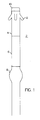
- FIG. 1 is a side view of an electrode illustrating a first embodiment of the invention.
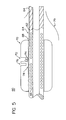
- FIG. 2 is a cross sectional view of the electrode of FIG. 1.
- FIG. 3 is a cross sectional view illustrating an electrode in accordance with a second embodiment of the invention.
- FIG. 4a is a cross sectional view of an electrode illustrating a third embodiment of the invention.
- FIG. 4b is a top view of the electrode of FIG. 4a.
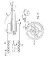
- FIG. 5 is a cross sectional view of an electrode in accordance with a fourth embodiment of the invention.
- FIG. 6 is a cross sectional view of an electrode illustrating a fifth embodiment of the invention.
- FIG. 7 is a perspective view of an electrode of yet another embodiment of the invention.
- Referring first to FIG. 1, an implantable electrode of the first embodiment of the present invention is shown. Electrode 2 is shown as a tubular element having two discharge regions,
metallized surface 6 andpacing tip 10. Theinner tubing 4 ofelectrode 2 is formed from a polymer biocompatible for implantation, and preferably is a silicone rubber polymer.Tines 12 are conventional, aiding with the fixation ofelectrode 2 in the desired location proximate the heart. - Referring to FIG. 2, a cross section of
electrode 2 is illustrated.Inner tubing 4 and outer tubing 18 form a coaxial lead, withouter conductor 14 coiling aroundinner tubing 4 andinner conductor 15 coiling within the interior ofinner tubing 4. Metallizedsurface 6 forms a band around the exterior ofinner tubing 4.Outer conductor 14 terminates in conductive contact withmetallized surface 6, being secured to metallizedsurface 6 viaconductive epoxy 16. To further secure the connection betweenouter conductor 14 and metallized surface 6 a high durometer (stiff)strain relief 8 is formed surrounding this connection and the end of outer tubing 18. - The
metallized surface 6 is formed by impregnating the desired location(s) on the outer surface ofinner tubing 4 with a metal. This impregnation preferably occurs by ion impregnation or ion enhanced metallization (high energy metal impregnation and deposition). Preferablyinner tubing 4 is formed from a polymer such as silicone rubber and the metal atoms used to impregnateinner tubing 4 are platinum. A high energy vapor or ion impregnation process impregnates the silicone rubber with platinum atoms, making themetallized surface 6 of thesilicone rubber tubing 4 conductive. This metallization "sticking" process also effectively eliminates the boundary conditions that would otherwise exist between these dissimilar materials. By eliminating the boundary conditions, this process also eliminates the high stress areas otherwise found around metal particles that could cause fatigue in high-flexed applications. Further, themetallized surface 6 typically includes one or more additional layers of metal deposited as a metallic film on the previously impregnated surface of the polymer. The previously impregnated metal in the polymer substrate provides an effective adhesion surface for the subsequent metallic coating, and effectively eliminates any discrete boundary or layering between the polymer substrate and the metallized surface. As can be appreciated, this elimination of discrete boundaries or layers provides for neutral stresses at the boundary and greatly improves the flex life of the metallic surface of theelectrode 2. - The depth of the conductivity of metallized
surface 6 can be determined as function of the energy applied during the impregnation, the ion mask of the metal impregnating the polymer, the focus, and the deposition time of the impregnation process. One skilled in the art may vary these parameters to obtain the desired thickness and conductivity of themetallised surface 6. Further, by altering the impregnation pattern and focus, different configurations of the metallizedsurface 6 can be formed on the surface of the polymer substrate. By using masks or other fixtures, any one of a number of configurations, including bands, concentric circles, spirals, and cross hatching, can be formed on the electrode surface. This important feature of the invention allows one skilled into the art to selectively tailor conductive configurations on the surface of an electrode to the desired application by varying the design, depth and conductivity of metallizedsurface 6 during the impregnation process. - Further, by metallizing the outer surface of
inner tubing 4, the need for a discrete metallic electrode is obviated and the required surface electrode diameter reduced. This in turn allows the overall diameter of the lead to be reduced. Further, the elimination of discrete metallic surface electrodes also eliminates the surface roughness associated with these discrete elements and reduces the stiffness of the lead at the location of the electrode. Thus, the use of metallizedsurface 6 in place of earlier types of discrete metallic electrodes allows for a thinner, smoother, and more flexible lead that will be less traumatic to the patient, easier to manipulate, and easier to remove chronically. - In order to maintain a smooth surface on the electrode at the point of connection between
outer conductor 14 and metallizedsurface 6, a moldedstrain relief 8 is formed over this connection.Mold 8 is preferably a high durometer (stiff) molded strain relief, made of a higher durometer rubber with feathered cross-section. - Turning to FIG. 3, an
electrode 22 of a second embodiment of the invention is illustrated.Outer tubing 24 is formed from a polymeric substrate, preferably a silicone rubber, with two metallizedsurfaces 26, 28 formed on the outer surface ofouter tubing 24 via impregnation of a metal in the polymeric substrate, the metal preferably being platinum. Conductors 30-33 are embedded in theouter tubing 24, withconductor 30 being conductively connected to metallizedsurface 26 andconductor 31 being conductively connected to metallized surface 28.Conductors Conductors surfaces 26, 28, and are preferably connected by the proximal placement of the termination ofconductors tubing 24 such that during the metallic impregnation process formingmetallised surfaces 26, 28 the impregnating metal penetrates sufficiently to form the desired conductive connection betweenmetallised surfaces 26, 28 andconductors - Conductors 30-33 are embedded in
tubing 24 such that the polymeric substrate oftubing 24 insulatively surrounds conductors 30-33. However, in a preferred embodiment further insulation 34-37 surround conductors 30-33, and is embedded intubing 24 along with conductors 30-33. -
Inner tubing 38 surroundsinner conductor 39, and in a preferred embodiment is used to connect the pulse of the generating system to a pacing tip electrode. Thus, in one embodiment of the present invention a lead 22 may incorporate a variety of different electrode configurations, such as one including a pacing tip, a bipolar ring, and two defibrillation electrodes while still allowing for a thin, smooth, and flexible electrode. - While metallized surfaces 26, 28 have been illustrated as rings on the surface of
outer tubing 24, one skilled in the art will appreciate that many different configurations of these metallized surfaces may be formed, and many different combinations of electrode surfaces may be placed on a given electrode. It is a particular advantage of the present invention that a variety of electrode surface configurations and combinations of electrode surfaces may be placed on a unitary electrode while still allowing the lead to be constructed as a thin, flexible, and smooth surface electrode. - In one embodiment, metallized surfaces 26, 28 are formed following the manufacture of
outer tubing 24. One skilled in the art will appreciate, however, that whenouter tubing 24 is formed by an extrusion process metallized surfaces 26, 28 may be formed by high energy metal deposition of the polymer substrate immediately following the extrusion of the substrate into the form ofouter tubing 24. An uncured silicone rubber may thus be used, and further, the heat, radiation or the like from the ion implantation process may be used to cure the unpolymerized material, allowing for a unique way in which to bond, affix and fabricate various subassemblies within the catheter or patch. - Turning now to FIG. 4a,
electrode 40 illustrates an alternate approach towards connecting the metallizedsurface 44 to anouter conductor 46. In this embodimentouter tubing 42,outer conductor coil 46,inner tubing 56, andinner conductor coil 58 together form a coaxial tubing, similar to thelead 2 illustrated in FIG. 1, such as may be used by for a simple bipolar lead. Unlikelead 2 in FIG. 2, however,conductor coil 46 inlead 40 is connected to metallizedsurface 44 by atermination ring 50 in this embodiment. Thus,outer conductor coil 46 is connected to thetermination ring 50 via aswage termination 52.Termination ring 50 is connected on its surface to metallizedsurface 44 via aconductive epoxy 48. FIG. 4b further illustrates a top view of such a termination ring assembly. - FIG. 5 illustrates an
electrode 60 according to a fourth embodiment of the present invention. In this embodiment a plurality of electrical conductors 66 are helically wound at a pre-determined pitch withintubing 62. At the desired location ametallised surface 64 is formed by impregnation intubing 62.Selected conductors 74 are lifted from the tubing structure and connected totermination collar 70, using a method similar to that disclosed in Dahl et al. U.S. Pat. No. 4,559,951. The selectedconductors 74 are lifted into slot 72 and swaged or crimped to thetermination collar 50 by means of swaging or crimpgroove 76. Slot 72 andgroove 76 are then back-filled with amedical adhesive 78. -
Termination collar 70 is conductively connected to metallizedsurface 64, preferably by means of a conductive epoxy joint 68. After the connections have been made, thetermination collar 50 and a portion of metallizedsurface 64 are then preferably encapsulated in astrain relief mold 79. - FIG. 6 illustrates a fifth embodiment of the present invention for use with a SQA termination for subcutaneous or epicardial electrodes.
Polymer tubing 90 andconductor 92 are joined viacylindrical terminal block 88 totubing 82 andconductor 93.Conductors terminal block 88, preferably by crimping via an access hole orslot 94.Metallized surface 84 ontubing 82 is connectively connected totermination collar 88 via a fully impregnated metallizedtubing 86 that is pressure fitted between metallizedsurface 84 andterminal block 88. Finally, moldedstrain relief 96 encapsulatesterminal block 88 and impregnatedtubing 86 while leaving a pre-determined portion of metallizedsurface 84 exposed. - The use of a metallized
surface 84 in a SQA termination, as illustrated in figure 6, minimizes the permanent deformation that is associated with crushed coils used in previous SQA electrodes. Instead, the SQA termination ofelectrode 80 relies on the compression of a fully impregnatedconductive tubing 86 between the SQA terminal block and metallizedsurface 84 for making the electrical connection. Thus, the chronic durability (fatigue resistance) of these electrodes is improved. Further, the use ofstrain relief molding 96 has the added benefit of providing a smoother connection and minimizing the potential for loss of electrical continuity due to abrasion on the termination connection. - FIG. 7 illustrates yet another embodiment of the present invention, as applied to a planar discharge region such as found on patch electrodes.
Electrode 100 consists of apolymeric substrate 102 formed into a planar surface configuration. A metallizedsurface 104 is formed in a desired configuration as a discharge surface in the planar region ofpolymeric substrate 102.Conductor 108 connects metallizedsurface 104 to lead 110, which is connected viaplug 112 topulse generating system 114. - As this figure illustrates, it is an advantage of the present invention that an electrical conducting surface of a desired configuration can be formed on a smooth planar surface by metallic impregnation. This is an improvement over prior patch electrode configurations using straight or undulating wires which have poor fatigue resistance; by eliminating such structures the screen fractures associated with such are similarly eliminated, improving electrode fatigue resistance. Further, the smoother surface associated with a metallized
surface 104 minimizes localized tissue trauma from the electrode. Moreover, the use of metallized surfaces facilitates chronic patch removal, by inhibiting tissue ingrowth, as well as the development of deployable electrodes using pre-stressed members, without the permanent deformation normally associated with metal parts. - Further, it is a particular advantage of the present invention that both complex and conventional electrode patterns may be readily formed, depending on the desired application. Further, undesirable current distributions can be smoothed in the electrode configuration by altering the conductivity throughout the electrode surface through variations in the impregnation parameters such as energy, ion mask, focus and deposition time. Further, in addition to forming a metallized surface region, it is also possible to form embedded conductors within the polymer substrate by means of a continuous feed extrusion system, where the depth and region of metallization are determined by feeding the extruded polymer between a stimulating electrode on one side and a conductor connecting the stimulating electrode to a terminal pin on the other side while varying the parameters of metal impregnation forming the stimulating electrode.
- The invention has been described here in considerable detail in order to provide those skilled in the art with information needed to apply the novel principals disclosed. However, one skilled in the art will appreciate that many different configurations and shapes of the electrode as described herein are possible. Further, it should be understood that the invention can be carried out by other different equipment and processes, and that various modifications, both as to physical details and operating functions, can be effected without departing from the scope of the invention itself. The description herein is intended by way of example only, and is not intended to limit the invention except as set forth in the following claims.
Claims (21)
1. An electrode adapted for implantation on or about a heart and for connection to a system for monitoring or stimulating cardiac activity, the electrode comprising:
a flexible polymeric substrate having an exposed surface layer;
a metal impregnated predetermined region of the exposed surface layer such that the impregnated region forms an electrical conducting surface;
an electrical conductor adapted for being electrically connected to the system; and
a connector conductively joining the conducting surface to the electrical conductor.
2. The electrode of claim 1 further comprising a strain relief encapsulating the connector and partially encapsulating the electrical conducting surface.
3. The electrode of claim 1 wherein the metal impregnated predetermined region comprises a silicone rubber substrate impregnated with platinum.
4. The electrode of claim 1 wherein the flexible polymeric substrate is a silicone rubber tube.
5. The electrode of claim 4 wherein the connector is a conductive adhesive adapted for joining the conductor to the conducting surface.
6. The electrode of claim 5 further comprising a strain relief surrounding the connector and conductive adhesive and partially surrounding the conductive surface, and an outer tubing coaxially disposed around the silicone rubber tube having a distal end terminating within the strain relief, and wherein the conductor is insulatively disposed between the silicone rubber tube and the outer tubing.
7. The electrode of claim 5 further comprising a second conducting surface at a distal end of the tube, and a second electrical conductor conductively connected to the second conducting surface at one end and the system at another end.
8. The electrode of claim 1 wherein a part of the impregnated region is the connector, such that the impregnated region conductively adjoins the electrical conductor.
9. The electrode of claim 8 wherein the flexible polymeric substrate is a silicone rubber tube, and the conductor is insulatively surrounded by the tube.
10. The electrode of claim 9 further comprising an inner tubing surrounded by the silicone rubber tube, a second conductor insulatively surrounded by the inner tubing and connected to the system, and an electrically conducting tip disposed at the distal end of the electrode and conductively connected to the second conductor.
11. The electrode of claim 1 wherein the electrical conducting surface is a substantially planar surface configuration.
12. The electrode of claim 1 wherein the connector comprises a termination ring conductively connected to the conductor, and a conductive adhesive joining the termination ring and the electrical conducting surface.
13. The electrode of claim 1 wherein the connector comprises a terminal block and a second polymeric substrate having a metal impregnated region across the width thereof, which region of the second polymeric substrate conductively connects the terminal block to the electrical conducting surface.
14. A biocompatible implantable electrode adapted for connection to a system for monitoring or stimulating electric activity, the electrode comprising:
a flexible polymeric substrate having an outer surface;
a metallized film impregnating a predetermined region of the outer surface such that the impregnated region forms an electrical conducting surface; and
an electrical conductor electrically connecting the electrical conducting surface to the system.
15. An implantable cardiac electrode adapted for connection to a cardiac monitoring and pulse generating system, the electrode comprising:
an elongated cardiac catheter having a distal active portion and a proximal lead portion, such proximal lead portion adapted for being electrically connected to the system;
a discharge surface region having a pre- determined surface configuration on the distal active portion;
a metallized film impregnating the discharge surface region such that the impregnated region forms an electrical conducting surface; and
a conductor electrically connecting the electrical conducting surface to the proximal lead portion.
16. A method for making an implantable electrode comprising:
forming a flexible polymeric electrode substrate having an outer surface layer;
depositing a metallized film on a predetermined region of the outer surface layer such that the metallized film impregnates the outer surface layer and forms an electrical conducting surface; and
connecting a conductor lead to the electrical conducting surface.
17. The method of claim 16 wherein the metallized film is deposited by ion impregnation.
18. The method of claim 16 wherein the metallized film is deposited by ion-enhanced metallization.
19. The method of claim 16 further comprising depositing an additional metallized film such that a metallic surface coating is formed on the impregnated outer surface layer.
20. The method of claim 16 wherein the steps of depositing the metallized film to form the electrical conducting surface and of connecting the conductive lead to the electrical conducting surface are the same step.
21. The method of claim 20 further comprising the step of impregnating the flexible polymeric substrate with the metallized film such that a conductive path is formed in the substrate that is insulatively surrounded by the substrate, the conductive path being a distal portion of the conductor lead and having a distal end capable of being connected to the electrical conducting surface.
Applications Claiming Priority (2)
| Application Number | Priority Date | Filing Date | Title |
|---|---|---|---|
| US2417693A | 1993-02-22 | 1993-02-22 | |
| US24176 | 1998-02-17 |
Publications (2)
| Publication Number | Publication Date |
|---|---|
| EP0612538A2 true EP0612538A2 (en) | 1994-08-31 |
| EP0612538A3 EP0612538A3 (en) | 1995-04-05 |
Family
ID=21819252
Family Applications (1)
| Application Number | Title | Priority Date | Filing Date |
|---|---|---|---|
| EP94100736A Withdrawn EP0612538A3 (en) | 1993-02-22 | 1994-01-19 | Metallized, implantable cardiac electrode. |
Country Status (5)
| Country | Link |
|---|---|
| US (1) | US5554178A (en) |
| EP (1) | EP0612538A3 (en) |
| JP (1) | JP2505371B2 (en) |
| AU (1) | AU5487494A (en) |
| CA (1) | CA2116188C (en) |
Cited By (20)
| Publication number | Priority date | Publication date | Assignee | Title |
|---|---|---|---|---|
| WO1997028668A1 (en) * | 1996-01-31 | 1997-08-07 | Cochlear Limited | Thin film fabrication technique for implantable electrodes |
| US5871529A (en) * | 1997-01-16 | 1999-02-16 | Cardiac Pacemakers, Inc. | Electrode for high impedance heart stimulation |
| US5913887A (en) | 1996-03-01 | 1999-06-22 | Cardiac Pacemakers, Inc. | Device for the transvenous cardioversion of atrial fibrillation or atrial flutter including three coil electrodes |
| US5916243A (en) | 1992-11-24 | 1999-06-29 | Cardiac Pacemakers, Inc. | Implantable conformal coil patch electrode with multiple conductive elements for cardioversion and defibrillation |
| US6085119A (en) | 1998-07-22 | 2000-07-04 | Cardiac Pacemakers, Inc. | Single pass endocardial lead for multi-site atrial pacing |
| US6152954A (en) | 1998-07-22 | 2000-11-28 | Cardiac Pacemakers, Inc. | Single pass lead having retractable, actively attached electrode for pacing and sensing |
| US6212434B1 (en) | 1998-07-22 | 2001-04-03 | Cardiac Pacemakers, Inc. | Single pass lead system |
| US6321122B1 (en) | 1998-07-22 | 2001-11-20 | Cardiac Pacemakers, Inc. | Single pass defibrillation/pacing lead with passively attached electrode for pacing and sensing |
| US6501994B1 (en) | 1997-12-24 | 2002-12-31 | Cardiac Pacemakers, Inc. | High impedance electrode tip |
| US6889092B2 (en) | 1999-09-24 | 2005-05-03 | Cardiac Pacemakers, Inc. | High impedance electrode assembly |
| US8285376B2 (en) | 2004-12-20 | 2012-10-09 | Cardiac Pacemakers, Inc. | Ventricular pacing |
| US8290586B2 (en) | 2004-12-20 | 2012-10-16 | Cardiac Pacemakers, Inc. | Methods, devices and systems for single-chamber pacing using a dual-chamber pacing device |
| US8326423B2 (en) | 2004-12-20 | 2012-12-04 | Cardiac Pacemakers, Inc. | Devices and methods for steering electrical stimulation in cardiac rhythm management |
| US8423139B2 (en) | 2004-12-20 | 2013-04-16 | Cardiac Pacemakers, Inc. | Methods, devices and systems for cardiac rhythm management using an electrode arrangement |
| US8538521B2 (en) | 2004-12-20 | 2013-09-17 | Cardiac Pacemakers, Inc. | Systems, devices and methods for monitoring efficiency of pacing |
| US8543203B2 (en) | 2004-12-20 | 2013-09-24 | Cardiac Pacemakers, Inc. | Endocardial pacing devices and methods useful for resynchronization and defibrillation |
| US8565880B2 (en) | 2010-04-27 | 2013-10-22 | Cardiac Pacemakers, Inc. | His-bundle capture verification and monitoring |
| US8688234B2 (en) | 2008-12-19 | 2014-04-01 | Cardiac Pacemakers, Inc. | Devices, methods, and systems including cardiac pacing |
| US8880169B2 (en) | 2004-12-20 | 2014-11-04 | Cardiac Pacemakers, Inc. | Endocardial pacing relating to conduction abnormalities |
| DE102019006709A1 (en) * | 2019-09-25 | 2021-03-25 | Heraeus Deutschland GmbH & Co. KG | Contacting flexible electrodes |
Families Citing this family (52)
| Publication number | Priority date | Publication date | Assignee | Title |
|---|---|---|---|---|
| US5876427A (en) * | 1997-01-29 | 1999-03-02 | Light Sciences Limited Partnership | Compact flexible circuit configuration |
| US6249708B1 (en) | 1997-08-26 | 2001-06-19 | Angeion Corporation | Fluted channel construction for a multi-conductor catheter lead |
| US6501990B1 (en) | 1999-12-23 | 2002-12-31 | Cardiac Pacemakers, Inc. | Extendable and retractable lead having a snap-fit terminal connector |
| US6463334B1 (en) | 1998-11-02 | 2002-10-08 | Cardiac Pacemakers, Inc. | Extendable and retractable lead |
| US6208881B1 (en) | 1998-10-20 | 2001-03-27 | Micropure Medical, Inc. | Catheter with thin film electrodes and method for making same |
| US6240322B1 (en) | 1998-11-04 | 2001-05-29 | Cardiac Pacemakers, Inc. | System and apparatus having low profile collapsible tines |
| US6477404B1 (en) | 2000-03-01 | 2002-11-05 | Cardiac Pacemakers, Inc. | System and method for detection of pacing pulses within ECG signals |
| US7013182B1 (en) * | 2000-05-04 | 2006-03-14 | Cardiac Pacemakers, Inc. | Conductive polymer sheath on defibrillator shocking coils |
| AUPR090300A0 (en) * | 2000-10-20 | 2000-11-16 | AMC Technologies Pty Limited | An electrical lead |
| US6509588B1 (en) | 2000-11-03 | 2003-01-21 | Cardiac Pacemakers, Inc. | Method for interconnecting anodes and cathodes in a flat capacitor |
| US6687118B1 (en) * | 2000-11-03 | 2004-02-03 | Cardiac Pacemakers, Inc. | Flat capacitor having staked foils and edge-connected connection members |
| US7456077B2 (en) | 2000-11-03 | 2008-11-25 | Cardiac Pacemakers, Inc. | Method for interconnecting anodes and cathodes in a flat capacitor |
| US6684102B1 (en) | 2000-11-03 | 2004-01-27 | Cardiac Pacemakers, Inc. | Implantable heart monitors having capacitors with endcap headers |
| US6699265B1 (en) | 2000-11-03 | 2004-03-02 | Cardiac Pacemakers, Inc. | Flat capacitor for an implantable medical device |
| US7355841B1 (en) | 2000-11-03 | 2008-04-08 | Cardiac Pacemakers, Inc. | Configurations and methods for making capacitor connections |
| US6833987B1 (en) | 2000-11-03 | 2004-12-21 | Cardiac Pacemakers, Inc. | Flat capacitor having an active case |
| US7107099B1 (en) | 2000-11-03 | 2006-09-12 | Cardiac Pacemakers, Inc. | Capacitor having a feedthrough assembly with a coupling member |
| US6522525B1 (en) | 2000-11-03 | 2003-02-18 | Cardiac Pacemakers, Inc. | Implantable heart monitors having flat capacitors with curved profiles |
| US20020128700A1 (en) * | 2001-03-08 | 2002-09-12 | Cross Thomas E. | Lead with adjustable angular and spatial relationships between electrodes |
| US7257449B2 (en) * | 2001-05-30 | 2007-08-14 | Cardiac Pacemakers, Inc. | Extendable/retractable lead having downsized lead body |
| US6701191B2 (en) * | 2001-05-30 | 2004-03-02 | Cardiac Pacemakers, Inc. | Lead having composite tubing |
| US6961621B2 (en) | 2001-12-04 | 2005-11-01 | Cardiac Pacemakers, Inc. | Apparatus and method for stabilizing an implantable lead |
| US6783645B2 (en) | 2001-12-18 | 2004-08-31 | Dionex Corporation | Disposable working electrode for an electrochemical cell |
| US6999821B2 (en) * | 2002-01-18 | 2006-02-14 | Pacesetter, Inc. | Body implantable lead including one or more conductive polymer electrodes and methods for fabricating same |
| US6866958B2 (en) * | 2002-06-05 | 2005-03-15 | General Motors Corporation | Ultra-low loadings of Au for stainless steel bipolar plates |
| US7231259B2 (en) | 2002-10-04 | 2007-06-12 | Pacesetter, Inc. | Body implantable lead comprising electrically conductive polymer conductors |
| US20040082986A1 (en) * | 2002-10-23 | 2004-04-29 | Randy Westlund | Unitary medical electrical lead and methods for making and using same |
| US7034441B2 (en) * | 2002-11-13 | 2006-04-25 | Nihon Dempa Kogyo Co., Ltd | Surface mount crystal unit and surface mount crystal oscillator |
| US7479349B2 (en) | 2002-12-31 | 2009-01-20 | Cardiac Pacemakers, Inc. | Batteries including a flat plate design |
| US7951479B2 (en) | 2005-05-11 | 2011-05-31 | Cardiac Pacemakers, Inc. | Method and apparatus for porous insulative film for insulating energy source layers |
| US7155293B2 (en) * | 2003-01-29 | 2006-12-26 | Cardiac Pacemakers, Inc. | Medical electrical lead employing load bearing sleeve |
| US7336998B2 (en) * | 2003-06-24 | 2008-02-26 | Cardiac Pacemakers, Inc. | External discrimination between pace pulses at different heart locations |
| US20050100774A1 (en) * | 2003-11-07 | 2005-05-12 | Abd Elhamid Mahmoud H. | Novel electrical contact element for a fuel cell |
| US7245973B2 (en) | 2003-12-23 | 2007-07-17 | Cardiac Pacemakers, Inc. | His bundle mapping, pacing, and injection lead |
| SE528688C2 (en) * | 2004-05-17 | 2007-01-23 | Anders Carlsson | Device for measuring temperature and heat content over a surface |
| US8101319B2 (en) * | 2004-05-20 | 2012-01-24 | GM Global Technology Operations LLC | Approach to make a high performance membrane electrode assembly (MEA) for a PEM fuel cell |
| US7224575B2 (en) | 2004-07-16 | 2007-05-29 | Cardiac Pacemakers, Inc. | Method and apparatus for high voltage aluminum capacitor design |
| CN101879347A (en) * | 2004-08-05 | 2010-11-10 | 导管治疗有限公司 | Be used to make the method for electric lead |
| US7401948B2 (en) * | 2005-10-17 | 2008-07-22 | Visteon Global Technologies, Inc. | Near field lens having reduced size |
| US7881808B2 (en) * | 2006-03-29 | 2011-02-01 | Cardiac Pacemakers, Inc. | Conductive polymeric coating with optional biobeneficial topcoat for a medical lead |
| US8761875B2 (en) | 2006-08-03 | 2014-06-24 | Cardiac Pacemakers, Inc. | Method and apparatus for selectable energy storage partitioned capacitor |
| US8455155B2 (en) * | 2006-11-22 | 2013-06-04 | GM Global Technology Operations LLC | Inexpensive approach for coating bipolar plates for PEM fuel cells |
| AU2010203373B2 (en) | 2009-01-12 | 2013-08-01 | University Of Massachusetts Lowell | Polyisobutylene-based polyurethanes |
| WO2011022583A1 (en) | 2009-08-21 | 2011-02-24 | Cardiac Pacemakers, Inc. | Crosslinkable polyisobutylene-based polymers and medical devices containing the same |
| US8644952B2 (en) | 2009-09-02 | 2014-02-04 | Cardiac Pacemakers, Inc. | Medical devices including polyisobutylene based polymers and derivatives thereof |
| US8374704B2 (en) | 2009-09-02 | 2013-02-12 | Cardiac Pacemakers, Inc. | Polyisobutylene urethane, urea and urethane/urea copolymers and medical leads containing the same |
| EP2709524A4 (en) * | 2011-05-20 | 2015-01-14 | Univ Central Florida Res Found | Surface modified materials for tailoring responses to electromagnetic fields |
| CN102824689B (en) * | 2012-09-07 | 2014-12-24 | 清华大学 | Implanted electrode and preparation method thereof and medical assembly comprising implanted electrode |
| JP2015535538A (en) | 2012-11-21 | 2015-12-14 | ユニバーシティー オブ マサチューセッツUniversity of Massachusetts | High strength polyisobutylene polyurethane |
| EP3592786B1 (en) | 2017-03-07 | 2023-05-10 | Cardiac Pacemakers, Inc. | Hydroboration/oxidation of allyl-terminated polyisobutylene |
| CN110997746B (en) | 2017-08-17 | 2021-12-28 | 心脏起搏器股份公司 | Photocrosslinked polymers for enhanced durability |
| EP3740253B1 (en) | 2018-01-17 | 2023-08-16 | Cardiac Pacemakers, Inc. | End-capped polyisobutylene polyurethane |
Citations (2)
| Publication number | Priority date | Publication date | Assignee | Title |
|---|---|---|---|---|
| FR2180907A1 (en) * | 1972-04-17 | 1973-11-30 | Medtronic Inc | |
| US4559951A (en) * | 1982-11-29 | 1985-12-24 | Cardiac Pacemakers, Inc. | Catheter assembly |
Family Cites Families (10)
| Publication number | Priority date | Publication date | Assignee | Title |
|---|---|---|---|---|
| US4224949A (en) * | 1977-11-17 | 1980-09-30 | Cornell Research Foundation, Inc. | Method and electrical resistance probe for detection of estrus in bovine |
| DE2822829A1 (en) * | 1978-05-24 | 1979-11-29 | Michael S Dipl Ing Lampadius | Bipolar electrode catheter for heart pacer - comprises cardial insertable tip and jacket electrode of vulcanised silicone rubber contg. conductive metal filler |
| JPH02107229A (en) * | 1988-10-15 | 1990-04-19 | Inax Corp | Electrode |
| US5016646A (en) * | 1988-11-29 | 1991-05-21 | Telectronics, N.V. | Thin electrode lead and connections |
| US5199433A (en) * | 1989-02-06 | 1993-04-06 | Arzco Medical Systems, Inc. | Esophageal recording/pacing catheter with thermistor and cardiac imaging transceiver |
| US5095905A (en) * | 1990-06-07 | 1992-03-17 | Medtronic, Inc. | Implantable neural electrode |
| JPH0714421B2 (en) * | 1990-06-12 | 1995-02-22 | オリンパス光学工業株式会社 | Thermotherapy device |
| US5109842A (en) * | 1990-09-24 | 1992-05-05 | Siemens Pacesetter, Inc. | Implantable tachyarrhythmia control system having a patch electrode with an integrated cardiac activity system |
| US5238006A (en) * | 1991-06-24 | 1993-08-24 | Medtronic, Inc. | Apnea stimulation lead |
| US5269810A (en) * | 1992-06-19 | 1993-12-14 | W. L. Gore & Associates, Inc. | Patch electrode |
-
1994
- 1994-01-19 EP EP94100736A patent/EP0612538A3/en not_active Withdrawn
- 1994-02-03 AU AU54874/94A patent/AU5487494A/en not_active Abandoned
- 1994-02-21 JP JP6022730A patent/JP2505371B2/en not_active Expired - Fee Related
- 1994-02-22 CA CA002116188A patent/CA2116188C/en not_active Expired - Fee Related
-
1995
- 1995-04-26 US US08/427,942 patent/US5554178A/en not_active Expired - Lifetime
Patent Citations (2)
| Publication number | Priority date | Publication date | Assignee | Title |
|---|---|---|---|---|
| FR2180907A1 (en) * | 1972-04-17 | 1973-11-30 | Medtronic Inc | |
| US4559951A (en) * | 1982-11-29 | 1985-12-24 | Cardiac Pacemakers, Inc. | Catheter assembly |
Non-Patent Citations (1)
| Title |
|---|
| IEEE TRANSACTIONS ON BIO-MEDICAL ENGINEERING, vol.BME-26, no.4, 1 April 1979, NEW YORK US pages 199 - 206 POCHAY,WISE,ALLARD,RUTLEDGE 'a multichannel depth probe fabricated using electron-beam lithography' * |
Cited By (40)
| Publication number | Priority date | Publication date | Assignee | Title |
|---|---|---|---|---|
| US6038483A (en) | 1992-11-24 | 2000-03-14 | Cardiac Pacemakers, Inc. | Implantable conformal coil patch electrode with multiple conductive elements for cardioversion and defibrillation |
| US5916243A (en) | 1992-11-24 | 1999-06-29 | Cardiac Pacemakers, Inc. | Implantable conformal coil patch electrode with multiple conductive elements for cardioversion and defibrillation |
| US6026332A (en) | 1992-11-24 | 2000-02-15 | Cardiac Pacemakers, Inc. | Implantable conformal coil patch electrode with multiple conductive elements for cardioversion and defibrillation |
| US6032079A (en) | 1992-11-24 | 2000-02-29 | Cardiac Pacemakers, Inc. | Implantable conformal coil electrode with multiple conductive elements for cardioversion and defibrillation |
| US6152955A (en) | 1992-11-24 | 2000-11-28 | Cardiac Pacemakers, Inc. | Implantable conformal coil patch electrode with multiple conductive elements for cardioversion and defibrillation |
| US5720099A (en) * | 1996-01-31 | 1998-02-24 | Cochlear Limited | Thin film fabrication technique for implantable electrodes |
| WO1997028668A1 (en) * | 1996-01-31 | 1997-08-07 | Cochlear Limited | Thin film fabrication technique for implantable electrodes |
| AU714520B2 (en) * | 1996-01-31 | 2000-01-06 | Cochlear Limited | Thin film fabrication technique for implantable electrodes |
| US5913887A (en) | 1996-03-01 | 1999-06-22 | Cardiac Pacemakers, Inc. | Device for the transvenous cardioversion of atrial fibrillation or atrial flutter including three coil electrodes |
| US6041256A (en) | 1996-03-01 | 2000-03-21 | Cardiac Pacemakers, Inc. | Device for the transvenous cardioversion of atrial fibrillation or atrial flutter |
| US6741894B2 (en) | 1996-03-01 | 2004-05-25 | Cardiac Pacemakers, Inc. | Device for the transvenous cardioversion of atrial fibrillation or atrial flutter |
| US5871529A (en) * | 1997-01-16 | 1999-02-16 | Cardiac Pacemakers, Inc. | Electrode for high impedance heart stimulation |
| US6501994B1 (en) | 1997-12-24 | 2002-12-31 | Cardiac Pacemakers, Inc. | High impedance electrode tip |
| US6212434B1 (en) | 1998-07-22 | 2001-04-03 | Cardiac Pacemakers, Inc. | Single pass lead system |
| US6321122B1 (en) | 1998-07-22 | 2001-11-20 | Cardiac Pacemakers, Inc. | Single pass defibrillation/pacing lead with passively attached electrode for pacing and sensing |
| US6345204B1 (en) | 1998-07-22 | 2002-02-05 | Cardiac Pacemakers, Inc. | Single pass lead having retractable, actively attached electrode for pacing and sensing |
| US6152954A (en) | 1998-07-22 | 2000-11-28 | Cardiac Pacemakers, Inc. | Single pass lead having retractable, actively attached electrode for pacing and sensing |
| US6085119A (en) | 1998-07-22 | 2000-07-04 | Cardiac Pacemakers, Inc. | Single pass endocardial lead for multi-site atrial pacing |
| US6889092B2 (en) | 1999-09-24 | 2005-05-03 | Cardiac Pacemakers, Inc. | High impedance electrode assembly |
| US8290586B2 (en) | 2004-12-20 | 2012-10-16 | Cardiac Pacemakers, Inc. | Methods, devices and systems for single-chamber pacing using a dual-chamber pacing device |
| US8812106B2 (en) | 2004-12-20 | 2014-08-19 | Cardiac Pacemakers, Inc. | Apparatus for treating the physiological electric conduction of the heart |
| US8326423B2 (en) | 2004-12-20 | 2012-12-04 | Cardiac Pacemakers, Inc. | Devices and methods for steering electrical stimulation in cardiac rhythm management |
| US8346358B2 (en) | 2004-12-20 | 2013-01-01 | Cardiac Pacemakers, Inc. | Pacemaker which reestablishes or keeps the physiological electric conduction of the heart and a method of application |
| US8423139B2 (en) | 2004-12-20 | 2013-04-16 | Cardiac Pacemakers, Inc. | Methods, devices and systems for cardiac rhythm management using an electrode arrangement |
| US8428715B2 (en) | 2004-12-20 | 2013-04-23 | Cardiac Pacemakers, Inc. | Methods for treating the physiological electric conduction of the heart |
| US8437848B2 (en) | 2004-12-20 | 2013-05-07 | Cardiac Pacemakers, Inc. | Apparatus for treating the physiological electric conduction of the heart |
| US8538521B2 (en) | 2004-12-20 | 2013-09-17 | Cardiac Pacemakers, Inc. | Systems, devices and methods for monitoring efficiency of pacing |
| US8543203B2 (en) | 2004-12-20 | 2013-09-24 | Cardiac Pacemakers, Inc. | Endocardial pacing devices and methods useful for resynchronization and defibrillation |
| US9031648B2 (en) | 2004-12-20 | 2015-05-12 | Cardiac Pacemakers, Inc. | Endocardial pacing devices and methods useful for resynchronization and defibrillation |
| US9008768B2 (en) | 2004-12-20 | 2015-04-14 | Cardiac Pacemakers, Inc. | Methods, devices and systems for cardiac rhythm management using an electrode arrangement |
| US8285376B2 (en) | 2004-12-20 | 2012-10-09 | Cardiac Pacemakers, Inc. | Ventricular pacing |
| US8825159B2 (en) | 2004-12-20 | 2014-09-02 | Cardiac Pacemakers, Inc. | Devices and methods for steering electrical stimulation in cardiac rhythm management |
| US8838238B2 (en) | 2004-12-20 | 2014-09-16 | Cardiac Pacemakers, Inc. | Ventricular pacing |
| US8880169B2 (en) | 2004-12-20 | 2014-11-04 | Cardiac Pacemakers, Inc. | Endocardial pacing relating to conduction abnormalities |
| US8903489B2 (en) | 2004-12-20 | 2014-12-02 | Cardiac Pacemakers, Inc. | Methods, devices and systems for single-chamber pacing using a dual-chamber pacing device |
| US8934969B2 (en) | 2004-12-20 | 2015-01-13 | Cardiac Pacemakers, Inc. | Systems, devices and methods for monitoring efficiency of pacing |
| US8688234B2 (en) | 2008-12-19 | 2014-04-01 | Cardiac Pacemakers, Inc. | Devices, methods, and systems including cardiac pacing |
| US8565880B2 (en) | 2010-04-27 | 2013-10-22 | Cardiac Pacemakers, Inc. | His-bundle capture verification and monitoring |
| DE102019006709A1 (en) * | 2019-09-25 | 2021-03-25 | Heraeus Deutschland GmbH & Co. KG | Contacting flexible electrodes |
| EP3799082A1 (en) | 2019-09-25 | 2021-03-31 | Heraeus Deutschland GmbH & Co KG | Method for contacting flexible electrodes |
Also Published As
| Publication number | Publication date |
|---|---|
| AU5487494A (en) | 1994-08-25 |
| JP2505371B2 (en) | 1996-06-05 |
| CA2116188A1 (en) | 1994-08-23 |
| CA2116188C (en) | 1999-06-08 |
| EP0612538A3 (en) | 1995-04-05 |
| JPH0739588A (en) | 1995-02-10 |
| US5554178A (en) | 1996-09-10 |
Similar Documents
| Publication | Publication Date | Title |
|---|---|---|
| US5554178A (en) | Metalized implantable cardiac electrode | |
| US5330520A (en) | Implantable electrode and sensor lead apparatus | |
| US4972846A (en) | Patch electrodes for use with defibrillators | |
| US5016808A (en) | Implantable tapered spiral endocardial lead for use in internal defibrillation | |
| US6564107B1 (en) | Coil-less lead system | |
| US5554176A (en) | Implantable electrode and sensor lead apparatus | |
| US5133365A (en) | Implantable tapered spiral endocardial lead for use in internal defibrillation | |
| US5411544A (en) | Defibrillation lead with improved mechanical and electrical characteristics | |
| EP1651305B1 (en) | Implantable electrical cable and method of making | |
| EP1888163B1 (en) | Methods of fabricating medical electrical electrodes with conductive polymer | |
| US4573481A (en) | Implantable electrode array | |
| US6516232B2 (en) | Ring electrode with porous member | |
| US5336254A (en) | Defibrillation lead employing electrodes fabricated from woven carbon fibers | |
| US5458629A (en) | Implantable lead ring electrode and method of making | |
| US5871529A (en) | Electrode for high impedance heart stimulation | |
| US6925334B1 (en) | Implantable medical lead having multiple, jointly insulated electrical conductors | |
| WO1980002231A1 (en) | Long-life flexible electrode lead | |
| US6606522B2 (en) | Torque mechanism and method for endocardial leads | |
| US7239923B1 (en) | Lead having varying stiffness and method of manufacturing thereof | |
| US8442650B2 (en) | Medical electrical lead with backfilled electrode sub-assembly | |
| US7558632B1 (en) | Method of manufacturing an implantable J-shaped lead |
Legal Events
| Date | Code | Title | Description |
|---|---|---|---|
| PUAI | Public reference made under article 153(3) epc to a published international application that has entered the european phase |
Free format text: ORIGINAL CODE: 0009012 |
|
| AK | Designated contracting states |
Kind code of ref document: A2 Designated state(s): AT BE CH DE DK ES FR GB GR IE IT LI LU MC NL PT SE |
|
| PUAL | Search report despatched |
Free format text: ORIGINAL CODE: 0009013 |
|
| AK | Designated contracting states |
Kind code of ref document: A3 Designated state(s): AT BE CH DE DK ES FR GB GR IE IT LI LU MC NL PT SE |
|
| STAA | Information on the status of an ep patent application or granted ep patent |
Free format text: STATUS: THE APPLICATION IS DEEMED TO BE WITHDRAWN |
|
| 18D | Application deemed to be withdrawn |
Effective date: 19951006 |