EP0608899A2 - Portable telephone and additional device for the same - Google Patents
Portable telephone and additional device for the same Download PDFInfo
- Publication number
- EP0608899A2 EP0608899A2 EP94101304A EP94101304A EP0608899A2 EP 0608899 A2 EP0608899 A2 EP 0608899A2 EP 94101304 A EP94101304 A EP 94101304A EP 94101304 A EP94101304 A EP 94101304A EP 0608899 A2 EP0608899 A2 EP 0608899A2
- Authority
- EP
- European Patent Office
- Prior art keywords
- portable telephone
- main body
- additional device
- power source
- connector
- Prior art date
- Legal status (The legal status is an assumption and is not a legal conclusion. Google has not performed a legal analysis and makes no representation as to the accuracy of the status listed.)
- Granted
Links
Images


Classifications
-
- H—ELECTRICITY
- H04—ELECTRIC COMMUNICATION TECHNIQUE
- H04M—TELEPHONIC COMMUNICATION
- H04M1/00—Substation equipment, e.g. for use by subscribers
- H04M1/02—Constructional features of telephone sets
- H04M1/0202—Portable telephone sets, e.g. cordless phones, mobile phones or bar type handsets
- H04M1/026—Details of the structure or mounting of specific components
- H04M1/0262—Details of the structure or mounting of specific components for a battery compartment
-
- H—ELECTRICITY
- H04—ELECTRIC COMMUNICATION TECHNIQUE
- H04B—TRANSMISSION
- H04B1/00—Details of transmission systems, not covered by a single one of groups H04B3/00 - H04B13/00; Details of transmission systems not characterised by the medium used for transmission
- H04B1/38—Transceivers, i.e. devices in which transmitter and receiver form a structural unit and in which at least one part is used for functions of transmitting and receiving
- H04B1/3827—Portable transceivers
- H04B1/3883—Arrangements for mounting batteries or battery chargers
-
- H—ELECTRICITY
- H04—ELECTRIC COMMUNICATION TECHNIQUE
- H04M—TELEPHONIC COMMUNICATION
- H04M1/00—Substation equipment, e.g. for use by subscribers
- H04M1/02—Constructional features of telephone sets
- H04M1/0202—Portable telephone sets, e.g. cordless phones, mobile phones or bar type handsets
- H04M1/0254—Portable telephone sets, e.g. cordless phones, mobile phones or bar type handsets comprising one or a plurality of mechanically detachable modules
-
- H—ELECTRICITY
- H04—ELECTRIC COMMUNICATION TECHNIQUE
- H04M—TELEPHONIC COMMUNICATION
- H04M1/00—Substation equipment, e.g. for use by subscribers
- H04M1/72—Mobile telephones; Cordless telephones, i.e. devices for establishing wireless links to base stations without route selection
- H04M1/724—User interfaces specially adapted for cordless or mobile telephones
- H04M1/72403—User interfaces specially adapted for cordless or mobile telephones with means for local support of applications that increase the functionality
- H04M1/72409—User interfaces specially adapted for cordless or mobile telephones with means for local support of applications that increase the functionality by interfacing with external accessories
-
- H—ELECTRICITY
- H04—ELECTRIC COMMUNICATION TECHNIQUE
- H04M—TELEPHONIC COMMUNICATION
- H04M2250/00—Details of telephonic subscriber devices
- H04M2250/14—Details of telephonic subscriber devices including a card reading device
Definitions
- the present invention relates to a portable telephone and an additional device detachably connected to the portable telephone.
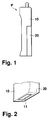
- a conventional portable telephone P has a portable telephone main body 10 and a battery 20 detachably attached to the portable telephone main body 10.
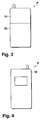
- the portable telephone main body 10 has, on its bottom, a connector 11 for connecting to external equipment, as shown in Figs. 1 to 4.
- the portable telephone main body 10 operates on power fed from the battery 20.
- a repeater 60 is required between the portable telephone main body 10 and the external equipment 40.
- the repeater 60 is a modem in order to provide a signal format converted into a digital signal and then fed to the external equipment 40.
- the power source or an additional device such as the repeater for increasing the functionality must be connected to the connector 11 of the portable telephone main body 10.
- the additional device is not integral with the portable telephone main body 10, so that the portability of the portable telephone P deteriorates.
- the Japanese Patent Application No. 99093/1992 discloses radio equipment which is detachably equipped with a battery pack.
- a lug is formed in the vicinity of the lower end of the radio main body.
- a locking piece and a knob are disposed on the upper side thereof, and a recess for engaging with the lug of the radio equipment main body is formed in the battery pack to facilitate the detachment of the battery.
- An object of the present invention is to provide a portable telephone of improved portability when a power source is additionally provided, external equipment is connected, or the functionality of the portable telephone is to be increased.
- an additional device for the portable telephone having a connecting member for detachably and integrally attaching to a portable telephone main body.
- a connecting member is also provided for detachably attaching to a power source.
- a power terminal portion of the additional device is capable of being detachably attached to a power terminal of the power source.
- the additional device can be detachably attached to the portable telephone main body having a connection function with a telephone line or network.
- the additional device can be detachably attached to a power source and has a power terminal capable of being detachably attached to a power terminal of the power source.
- various functions are provided for the portable telephone, whereby a device connected as an external device can be integrally mounted on the portable telephone main body to improve the portability.
- the additional device itself has a power source section whereby the stand-by time and conversation time can be prolonged.
- the additional equipment for the portable telephone has a modem function
- computer communication can be established by connecting to a communication terminal or the like by the use of a connector set.
- the additional device for the portable telephone can have an extension function for extending the functionality of the portable telephone, memory capacity and the like can be extended by attaching the additional device to the portable telephone main body.
- a chip type IC card can be received in the additional device, where the function of the portable telephone can be extended in accordance with the information stored in this chip type IC card.
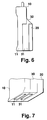
- a portable telephone in this embodiment comprises a portable telephone main body 10, an additional device 30 connected to and detachably attached to the portable telephone main body 10, and a battery 20 connected to and detachably attached to the additional device 30.
- the portable telephone main body 10 has a connector 11 for external connection.
- the additional device 30 for the portable telephone also has a connector 31 for external connection.
- Each of the connectors 11 and 31 is constituted of multipolar pins and provides connection for a power source and for input/output of signals.
- the connector 31 provides different functions to the device 30 for the portable telephone. As mentioned above, various types of devices having different functions can be prepared, and the user can select the desirable type, as needed.
- the additional device 30 for the portable telephone is detachable from the portable telephone main body 10.
- the power source or battery 20 is also detachable from the additional device 30.
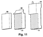
- the battery 20 is also detachable from the portable telephone main body 10. That is, as shown in Fig. 10, the hatched surface of the additional device 30 which faces the portable telephone main body 10 is formed so as to have the same shape and the same size as the hatched surface of the battery 20 facing the additional device 30. Furthermore, as shown in Fig. 11, the hatched surface of the portable telephone main body 10 which faces the additional device 30 is formed so as to have the same shape and the same size as the hatched surface of the additional device 30 facing the battery 20.
- the functionality of the portable telephone can be extended by simply providing the additional intermediate device 30 in the portable telephone arrangement.
- the conventional portable telephone comprising the portable telephone main body 10 and the battery 20 can still be utilized as it is or extended with the additional device.
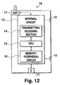
- the portable telephone main body 10 has the function of the portable telephone. As shown in Fig. 12, this portable telephone main body 10 has a connector 11, a battery terminal 12, an internal circuit 13 and an antenna 17. This internal circuit 13 has a transmitting/receiving section 14, a CPU 15 and a memory/peripheral circuit 16.
- additional devices 30 for the portable telephone can be prepared, and they can be optionally exchanged by the user of the portable telephone. Next, some embodiments of the additional devices for the portable telephone will be described.
- an additional device 30a for the portable telephone having a battery function will be described.
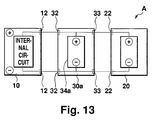
- the additional device 30a as shown in Fig. 13, has a power source section 34a, a battery terminal 32 for connection to the portable telephone main body 10, and a battery terminal 33 for connection to the battery 20. Not only the power source section 34a of this additional device 30a but also the battery 20 are electrically chargeable.
- the battery terminal 32 for connecting to the portable telephone main body 10 is formed so as to have the same shape as a battery terminal 22 disposed on the normal power source or battery 20.
- the battery terminal 33 for connecting to the battery 20 is formed so as to have the same shape as the battery terminal 12 provided in the portable telephone main body 10.
- the mutually facing terminals are symmetrically formed.
- An electric current is provided to an internal circuit showed in Fig. 13 through the battery terminals 12, 32, 33, 22.
- the portable telephone main body 10 and the additional device 30a can be detachably attached to each other by the battery terminal 12 and the battery terminal 32.
- the additional device 30a and the battery 20 can be detachably attached to each other by the battery terminal 33 and the battery terminal 22. It is possible to connect the respective parts to each other by connecting members other than the battery terminals 12, 32, 33, 22.
- the shape and the constitution of the additional device 30a are the same as shown in Figs. 6 to 11.
- the installation of the additional device 30a for the portable telephone permits prolonging the stand-by time and the conversation time which have been short when using the battery 20 alone.
- This principle is the same as the parallel connection of dry cells, whereby the telephone use time can be prolonged.
- the additional device 30a having the battery function has been described.
- the additional device 30b for the portable telephone is equipped with a modem function which is required for computer communication or the like.
- a portable telephone B as shown in Fig 14, comprises the portable telephone main body 10, the additional device 30b for the portable telephone, the power source or battery 20 and a connector set 50.
- the shape of the portable telephone main body 10, the additional device 30b and the battery 20 is the same as shown in Figs. 6 to 11.
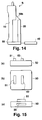
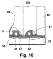
- the connector set 50 has a connector 51 for connection to the portable telephone main body 10, a connector 53 for connection to the additional device 30b for the portable telephone, and a connector 55 for connection to external equipment 40, as shown in Fig. 16.
- the connectors 51, 53 are arranged on a substrate 57 disposed in the connector set 50. Each of these connectors 51, 53, 55 comprises multipolar pins.
- the connector 51 is detachably engaged with the connector 11 of the portable telephone main body 10.
- the connector 53 is detachably engaged with the connector 31 of the additional device 30b for the portable telephone.
- the portable telephone main body 10 and the additional device 30b for the portable telephone are connected to the connector set 50, and therefore fixation therebetween can be strengthened.
- the external equipment 40 is, for example, a communication terminal for computer communication.
- the portable telephone main body 10 is electrically connected to the additional device 30b for the portable telephone having a modem function via the connector set 50.
- a signal from the external equipment 40 as the communication terminal connected to the connector set 50 is transmitted to an internal circuit 32b via the connector 55, the connector 53 and the connector 31 of the additional device 30b for the portable telephone.
- the signal from the external equipment 40 is processed. That is, the digital signal from the external equipment 40 is converted into an analog signal.
- This analog signal is transmitted to the portable telephone main body 10 via the connector 31, the connector 53 of the connector set 50, the connector 51 and the connector 11 of the portable telephone main body 10.
- the portable telephone main body 10 connects the input signal to a telephone network, thereby carrying out computer communication. That is, the CPU 15 in the internal circuit 13 processes the signal so as to be suitable for the portable telephone, for example, converts the signal into a digital signal.
- the transmitting/receiving section 14 then transmits the signal via the antenna 17. Incidentally, the reception of the signal can be carried out by reversing the procedure of the signal transmission.
- power is fed from the battery 20 connected to the additional device 30b, but the external equipment 40 as well as an external power source 45 may be connected to the connector 55 of the connector set 50.
- the portable telephone main body 10 is connected to the additional device 30a and the battery 20 as shown in Fig. 12.
- the power of the battery 20 can be fed to the portable telephone main body 10 via the additional device 30a, as shown by an arrow in Fig. 18 (a).
- the power supply from the battery 20 to the additional device 30b is carried out via the battery terminals 22, 33, as shown in Fig. 18 (b).
- the power supply to the portable telephone main body 10 is carried out via the connector set 50. That is, the power is fed from the additional device 30b to the portable telephone main body 10 via the connectors 53, 51.
- the connector set 50 is connected to the additional device 30b.
- a switch 38b disconnects the power feed line extending to the battery 20 by the operation of the internal circuit and connects a line extending to the external power source 45, so that the power supply to the additional device 30b can be achieved by power supply to the internal circuit 32b via the connectors 55, 53 and the switch 38b.
- Power supply to the portable telephone main body 10 is achieved by feeding the power to the internal circuit 13 via the connectors 53, 51.
- the external equipment 40 is also connected to the connector set 50 via the connector 55, and the signal from the external equipment 40 is processed in the internal circuit 32b, as in the case of Fig. 17. Afterward, the processed signal is transmitted to the internal circuit 13 of the portable telephone main body 10.
- the additional device 30b for the portable telephone has the modem function
- data can be transferred between distantly separated computers.
- the external power source 45 is provided, the data transfer is possible for a long period of time.
- a portable telephone C of the third embodiment has a similar constitution as in the second embodiment except that the communication terminal, which is the external equipment 40 in the second embodiment, is replaced with a device having a facsimile function.
- the additional device 30b has a function for sending/receiving data between the external equipment 40 as the facsimile and the portable telephone main body 10.
- the usual facsimile has a modem therein, and therefore FAX communication is carried out by directly connecting the facsimile to the connector 11 of the portable telephone main body 10.
- the additional devices 30a or 30b for the portable telephone had the battery function, the analog/digital terminal, or the multimedia function.
- this fourth embodiment has an extension function for extending the function of the portable telephone main body.
- a portable telephone D of the fourth embodiment the constitution of the portable telephone main body 10 and the battery 20 is the same as shown in Figs. 6 to 11.
- the constitution of the connector set 50 is the same as in the second embodiment.
- the additional device 30d for the portable telephone has a CPU 33d and a memory/peripheral circuit 34c, as shown in Fig. 20.
- the CPU 15 in the internal circuit 13 in the portable telephone main body 10 is connected to the CPU 33d by serial communication, and sending/receiving of data can be carried out between both the CPUs.
- the additional installation of the CPU 33d and the memory/peripheral circuit 34d permits extending the function of the portable telephone main body 10. That is, according to the fourth embodiment, a memory capacity can be increased, the function of conversation recording and absence-during-recording can be extended, and such various functions as in a portable telephone can be provided.
- a portable telephone E according to this fifth embodiment also has a mechanism for extending the functionality of the portable telephone, as in the above-mentioned fourth embodiment.
- the additional device 30e for the portable telephone functions as a chip type IC card receiving device.
- the additional device 30e for the portable telephone has a card gate 35e into which a chip type IC card 37e is inserted.
- the chip type IC card 37e can be completely arranged in the additional device 30e through this card gate 35e.
- the additional device 30e has a card ejection switch 36e. When this card ejection switch 36e is pushed, the chip type IC card 37e can be ejected by a soft-based or a hard-based drive.
- the additional device 30e for the portable telephone has the connector 31, battery terminal 33, a CPU 33e, a peripheral circuit 34e and a card interface circuit 38e therein, as in the above-mentioned embodiment.
- the constitution of the portable telephone main body 10 and the battery 20 is the same as in the case of the embodiments shown in Figs. 6 to 11.
- the usage of the additional device 30e for the portable telephone in this embodiment will be described.
- the reading of the information in the chip type IC card 37e and the predetermined processing of a signal are carried out by the card interface circuit 38e, the peripheral circuit 34e and the CPU 33e.
- An information signal is sent to the internal circuit 13 in the portable telephone main body 10, as shown in Fig. 25.
- the function of the portable telephone main body 10 can be extended in accordance with the information on the chip type IC card 37e.
- a function such as the increase of memory capacity for telephone numbers by abbreviated dialling can be extended. That is, the function of the portable telephone main body 10 can be extended or changed by simply preparing specific IC cards 37e and selecting a desirable one from the prepared cards.
Abstract
Description
- The present invention relates to a portable telephone and an additional device detachably connected to the portable telephone.
- A conventional portable telephone P has a portable telephone
main body 10 and abattery 20 detachably attached to the portable telephonemain body 10. The portable telephonemain body 10 has, on its bottom, aconnector 11 for connecting to external equipment, as shown in Figs. 1 to 4. - In the portable telephone P having the above-mentioned constitution, the portable telephone
main body 10 operates on power fed from thebattery 20. - However, when a power source is additionally provided in order to prolong the conversation time of the portable telephone
main body 10, it is necessary to connect an external power source to theconnector 11 for external equipment connection disposed in the portable telephonemain body 10. - As shown in Fig. 5, in order to connect
external equipment 40 to the portable telephone P having the above-mentioned constitution, arepeater 60 is required between the portable telephonemain body 10 and theexternal equipment 40. For example, when the portable telephonemain body 10 is connected to theexternal equipment 40 as a terminal for computer communication, an analog or digital signal is fed from the portable telephonemain body 10. In case of an analog signal, therepeater 60 is a modem in order to provide a signal format converted into a digital signal and then fed to theexternal equipment 40. - That is, when the conventional portable telephone with a power source is connected to the external equipment or modified to increase functions, the power source or an additional device such as the repeater for increasing the functionality must be connected to the
connector 11 of the portable telephonemain body 10. As a consequence, the additional device is not integral with the portable telephonemain body 10, so that the portability of the portable telephone P deteriorates. - The Japanese Patent Application No. 99093/1992 discloses radio equipment which is detachably equipped with a battery pack. In this radio equipment, a lug is formed in the vicinity of the lower end of the radio main body. A locking piece and a knob are disposed on the upper side thereof, and a recess for engaging with the lug of the radio equipment main body is formed in the battery pack to facilitate the detachment of the battery.
- An object of the present invention is to provide a portable telephone of improved portability when a power source is additionally provided, external equipment is connected, or the functionality of the portable telephone is to be increased.
- According to the invention an additional device for the portable telephone is provided having a connecting member for detachably and integrally attaching to a portable telephone main body. A connecting member is also provided for detachably attaching to a power source. A power terminal portion of the additional device is capable of being detachably attached to a power terminal of the power source. In the portable telephone of the present invention, the additional device can be detachably attached to the portable telephone main body having a connection function with a telephone line or network. The additional device can be detachably attached to a power source and has a power terminal capable of being detachably attached to a power terminal of the power source. According to the additional device of the present invention, various functions are provided for the portable telephone, whereby a device connected as an external device can be integrally mounted on the portable telephone main body to improve the portability.
- In one embodiment the additional device itself has a power source section whereby the stand-by time and conversation time can be prolonged. When the above-mentioned additional equipment for the portable telephone has a modem function, computer communication can be established by connecting to a communication terminal or the like by the use of a connector set. Furthermore, the additional device for the portable telephone can have an extension function for extending the functionality of the portable telephone, memory capacity and the like can be extended by attaching the additional device to the portable telephone main body. In a further embodiment a chip type IC card can be received in the additional device, where the function of the portable telephone can be extended in accordance with the information stored in this chip type IC card.
- Fig. 1
- is a front view illustrating a conventional portable telephone.
- Fig. 2
- is an enlarged perspective view of the bottom of the portable telephone shown in Fig. 1.
- Fig. 3
- is a right side view of the portable telephone shown in Fig. 1.
- Fig. 4
- is a left side view of the portable telephone shown in Fig. 1.
- Fig. 5
- is an explanatory view illustrating a use state of the conventional portable telephone.
- Fig. 6
- is a front view of a portable telephone in an embodiment of the present invention.
- Fig. 7
- is an enlarged perspective view of the bottom of the portable telephone shown in Fig. 6.
- Fig. 8
- is a right side view of the portable telephone shown in Fig. 6.
- Fig. 9
- is a left side view of the portable telephone shown in Fig. 6.
- Fig. 10
- is an exploded perspective view of the portable telephone.
- Fig. 11
- is an exploded perspective view of the portable telephone.
- Fig. 12
- is a constitutional view illustrating the constitution of the portable telephone main body.
- Fig. 13
- is a constitutional view illustrating the constitution of an additional device for the portable telephone in the first embodiment.
- Fig. 14
- is a front view illustrating a use state of the portable telephone utilizing an additional device for the portable telephone in the second embodiment.
- Fig. 15a
- is a front view of a connector set.
- Fig. 15b
- is a plan view of the connector set.
- Fig. 15c
- is a right side view of the connector set.
- Fig. 16
- is a partially broken sectional view illustrating a connection state between the connector set and other members.
- Fig. 17
- is a constitutional view illustrating the constitution of the portable telephone in the second embodiment.
- Fig. 18a
- is an explanatory view illustrating a power source feed direction in the case of the first embodiment.
- Fig. 18b
- is an explanatory view illustrating a power source feed direction in the case that a power source is fed from a battery in the second embodiment.
- Fig. 18c
- is an explanatory view illustrating a power source feed direction in the case that a power source is fed from an external power source in the second embodiment.
- Fig. 19
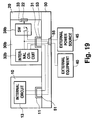
- is a constitutional view illustrating the constitution in which the external power source is connected in the second embodiment.
- Fig. 20
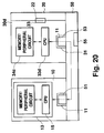
- is a constitutional view illustrating the constitution of the fourth embodiment.
- Fig. 21a
- is a plan view of an additional device for the portable telephone in the fifth embodiment.
- Fig. 21b
- is its front view.
- Fig. 21c
- is its base view.
- Fig. 21d
- is its rear view.
- Fig. 21e
- is its right side view.
- Fig. 22
- is a perspective view illustrating the additional device for the portable telephone and a chip type IC card in the fifth embodiment.
- Fig. 23
- is a plan view of the additional device for the portable telephone in the fifth embodiment.
- Fig. 24
- is a partially enlarged view of the additional device in Fig. 22.
- Fig. 25
- is a constitutional view illustrating the constitution of the portable telephone in the fifth embodiment.
- Embodiments of the present invention will be described with reference to drawings. In the drawings, the same members as the conventional members and corresponding portions are represented by the same numerals, and their description will be omitted.
- As shown in Fig. 6, a portable telephone in this embodiment comprises a portable telephone
main body 10, anadditional device 30 connected to and detachably attached to the portable telephonemain body 10, and abattery 20 connected to and detachably attached to theadditional device 30. Furthermore, as shown in Figs. 6, 7, 10 and 11, the portable telephonemain body 10 has aconnector 11 for external connection. Theadditional device 30 for the portable telephone also has aconnector 31 for external connection. Each of theconnectors connector 31 provides different functions to thedevice 30 for the portable telephone. As mentioned above, various types of devices having different functions can be prepared, and the user can select the desirable type, as needed. - As described above, the
additional device 30 for the portable telephone is detachable from the portable telephonemain body 10. The power source orbattery 20 is also detachable from theadditional device 30. In addition, thebattery 20 is also detachable from the portable telephonemain body 10. That is, as shown in Fig. 10, the hatched surface of theadditional device 30 which faces the portable telephonemain body 10 is formed so as to have the same shape and the same size as the hatched surface of thebattery 20 facing theadditional device 30. Furthermore, as shown in Fig. 11, the hatched surface of the portable telephonemain body 10 which faces theadditional device 30 is formed so as to have the same shape and the same size as the hatched surface of theadditional device 30 facing thebattery 20. Thus, the functionality of the portable telephone can be extended by simply providing the additionalintermediate device 30 in the portable telephone arrangement. The conventional portable telephone comprising the portable telephonemain body 10 and thebattery 20 can still be utilized as it is or extended with the additional device. - The portable telephone
main body 10 has the function of the portable telephone. As shown in Fig. 12, this portable telephonemain body 10 has aconnector 11, abattery terminal 12, aninternal circuit 13 and anantenna 17. Thisinternal circuit 13 has a transmitting/receivingsection 14, aCPU 15 and a memory/peripheral circuit 16. - Various types of
additional devices 30 for the portable telephone can be prepared, and they can be optionally exchanged by the user of the portable telephone. Next, some embodiments of the additional devices for the portable telephone will be described. - In the first embodiment, an
additional device 30a for the portable telephone having a battery function will be described. Theadditional device 30a, as shown in Fig. 13, has apower source section 34a, abattery terminal 32 for connection to the portable telephonemain body 10, and abattery terminal 33 for connection to thebattery 20. Not only thepower source section 34a of thisadditional device 30a but also thebattery 20 are electrically chargeable. Thebattery terminal 32 for connecting to the portable telephonemain body 10 is formed so as to have the same shape as abattery terminal 22 disposed on the normal power source orbattery 20. Thebattery terminal 33 for connecting to thebattery 20 is formed so as to have the same shape as thebattery terminal 12 provided in the portable telephonemain body 10. In addition, the mutually facing terminals are symmetrically formed. An electric current is provided to an internal circuit showed in Fig. 13 through thebattery terminals main body 10 and theadditional device 30a can be detachably attached to each other by thebattery terminal 12 and thebattery terminal 32. Theadditional device 30a and thebattery 20 can be detachably attached to each other by thebattery terminal 33 and thebattery terminal 22. It is possible to connect the respective parts to each other by connecting members other than thebattery terminals additional device 30a are the same as shown in Figs. 6 to 11. - The installation of the
additional device 30a for the portable telephone permits prolonging the stand-by time and the conversation time which have been short when using thebattery 20 alone. This principle is the same as the parallel connection of dry cells, whereby the telephone use time can be prolonged. - Next, the second embodiment will be described. In the above-mentioned first embodiment, the
additional device 30a having the battery function has been described. In the second embodiment, theadditional device 30b for the portable telephone is equipped with a modem function which is required for computer communication or the like. - A portable telephone B, as shown in Fig 14, comprises the portable telephone
main body 10, theadditional device 30b for the portable telephone, the power source orbattery 20 and aconnector set 50. The shape of the portable telephonemain body 10, theadditional device 30b and thebattery 20 is the same as shown in Figs. 6 to 11. The connector set 50 has aconnector 51 for connection to the portable telephonemain body 10, aconnector 53 for connection to theadditional device 30b for the portable telephone, and aconnector 55 for connection toexternal equipment 40, as shown in Fig. 16. Theconnectors substrate 57 disposed in the connector set 50. Each of theseconnectors connector 51 is detachably engaged with theconnector 11 of the portable telephonemain body 10. Theconnector 53 is detachably engaged with theconnector 31 of theadditional device 30b for the portable telephone. As described above, the portable telephonemain body 10 and theadditional device 30b for the portable telephone are connected to the connector set 50, and therefore fixation therebetween can be strengthened. In this case, theexternal equipment 40 is, for example, a communication terminal for computer communication. - Next, the usage of the portable telephone B regarding the second embodiment will be described. As shown in Fig. 17, the portable telephone
main body 10 is electrically connected to theadditional device 30b for the portable telephone having a modem function via the connector set 50. A signal from theexternal equipment 40 as the communication terminal connected to the connector set 50 is transmitted to aninternal circuit 32b via theconnector 55, theconnector 53 and theconnector 31 of theadditional device 30b for the portable telephone. In thisinternal circuit 32b, the signal from theexternal equipment 40 is processed. That is, the digital signal from theexternal equipment 40 is converted into an analog signal. This analog signal is transmitted to the portable telephonemain body 10 via theconnector 31, theconnector 53 of the connector set 50, theconnector 51 and theconnector 11 of the portable telephonemain body 10. The portable telephonemain body 10 connects the input signal to a telephone network, thereby carrying out computer communication. That is, theCPU 15 in theinternal circuit 13 processes the signal so as to be suitable for the portable telephone, for example, converts the signal into a digital signal. The transmitting/receivingsection 14 then transmits the signal via theantenna 17. Incidentally, the reception of the signal can be carried out by reversing the procedure of the signal transmission. - In the above-mentioned second embodiment, power is fed from the
battery 20 connected to theadditional device 30b, but theexternal equipment 40 as well as anexternal power source 45 may be connected to theconnector 55 of the connector set 50. - Now, the connection of the
battery 20 to other equipment will be described. In the portable telephone A of the first embodiment, the portable telephonemain body 10 is connected to theadditional device 30a and thebattery 20 as shown in Fig. 12. Thus the power of thebattery 20 can be fed to the portable telephonemain body 10 via theadditional device 30a, as shown by an arrow in Fig. 18 (a). - Furthermore, in the above-mentioned second embodiment, the power supply from the
battery 20 to theadditional device 30b is carried out via thebattery terminals main body 10 is carried out via the connector set 50. That is, the power is fed from theadditional device 30b to the portable telephonemain body 10 via theconnectors - In the case that the power is fed from the
external power source 45, power is supplied to the portable telephonemain body 10 and theadditional device 30b via theconnector 55 of the connector set 50 and theconnectors external power source 45 will be described in more detail. As shown in Fig. 19, the connector set 50 is connected to theadditional device 30b. Aswitch 38b disconnects the power feed line extending to thebattery 20 by the operation of the internal circuit and connects a line extending to theexternal power source 45, so that the power supply to theadditional device 30b can be achieved by power supply to theinternal circuit 32b via theconnectors main body 10 is achieved by feeding the power to theinternal circuit 13 via theconnectors external power source 45 is connected, theexternal equipment 40 is also connected to the connector set 50 via theconnector 55, and the signal from theexternal equipment 40 is processed in theinternal circuit 32b, as in the case of Fig. 17. Afterward, the processed signal is transmitted to theinternal circuit 13 of the portable telephonemain body 10. - As described above, when the
additional device 30b for the portable telephone has the modem function, data can be transferred between distantly separated computers. When theexternal power source 45 is provided, the data transfer is possible for a long period of time. - A portable telephone C of the third embodiment has a similar constitution as in the second embodiment except that the communication terminal, which is the
external equipment 40 in the second embodiment, is replaced with a device having a facsimile function. In this case, theadditional device 30b has a function for sending/receiving data between theexternal equipment 40 as the facsimile and the portable telephonemain body 10. The usual facsimile has a modem therein, and therefore FAX communication is carried out by directly connecting the facsimile to theconnector 11 of the portable telephonemain body 10. - Next, the fourth embodiment will be described. In the above-mentioned first to third embodiments, the
additional devices - In a portable telephone D of the fourth embodiment, the constitution of the portable telephone
main body 10 and thebattery 20 is the same as shown in Figs. 6 to 11. The constitution of the connector set 50 is the same as in the second embodiment. However, theadditional device 30d for the portable telephone has aCPU 33d and a memory/peripheral circuit 34c, as shown in Fig. 20. TheCPU 15 in theinternal circuit 13 in the portable telephonemain body 10 is connected to theCPU 33d by serial communication, and sending/receiving of data can be carried out between both the CPUs. As described above, the additional installation of theCPU 33d and the memory/peripheral circuit 34d permits extending the function of the portable telephonemain body 10. That is, according to the fourth embodiment, a memory capacity can be increased, the function of conversation recording and absence-during-recording can be extended, and such various functions as in a portable telephone can be provided. - Next, the fifth embodiment of the present invention will be described. A portable telephone E according to this fifth embodiment also has a mechanism for extending the functionality of the portable telephone, as in the above-mentioned fourth embodiment.
- That is, the
additional device 30e for the portable telephone functions as a chip type IC card receiving device. As shown in Figs. 21 to 24, theadditional device 30e for the portable telephone has acard gate 35e into which a chiptype IC card 37e is inserted. The chiptype IC card 37e can be completely arranged in theadditional device 30e through thiscard gate 35e. Furthermore, theadditional device 30e has acard ejection switch 36e. When thiscard ejection switch 36e is pushed, the chiptype IC card 37e can be ejected by a soft-based or a hard-based drive. - Moreover, the
additional device 30e for the portable telephone has theconnector 31,battery terminal 33, aCPU 33e, aperipheral circuit 34e and acard interface circuit 38e therein, as in the above-mentioned embodiment. In this respect, the constitution of the portable telephonemain body 10 and thebattery 20 is the same as in the case of the embodiments shown in Figs. 6 to 11. - The usage of the
additional device 30e for the portable telephone in this embodiment will be described. The reading of the information in the chiptype IC card 37e and the predetermined processing of a signal are carried out by thecard interface circuit 38e, theperipheral circuit 34e and theCPU 33e. An information signal is sent to theinternal circuit 13 in the portable telephonemain body 10, as shown in Fig. 25. In this way, the function of the portable telephonemain body 10 can be extended in accordance with the information on the chiptype IC card 37e. For example, a function such as the increase of memory capacity for telephone numbers by abbreviated dialling can be extended. That is, the function of the portable telephonemain body 10 can be extended or changed by simply preparingspecific IC cards 37e and selecting a desirable one from the prepared cards.
Claims (15)
- An additional device suitable for use in a portable telephone arrangement comprising a portable telephone main body and a power source, said additional device comprising:
a connecting member for detachably and integrally attaching the additional device (30a, b) to said portable telephone main body (10);
a connecting member for detachably attaching the additional device (30a, b) to said power source (20); and
a power terminal portion (33) detachably attachable to a power terminal portion (22) of said power source (20). - The additional device for a portable telephone according to claim 1 further comprising a power source section (34a) for supplying power to the portable telephone main body (10), and a power terminal portion (32) detachably attachable to a power terminal portion (12) of the portable telephone main body (10).
- The additional device for a portable telephone according to claim 1 or 2 further comprising a connector (31, 53) for connection to external equipment (40), providing a modem function for modulating/demodulating an input signal.
- The additional device for a portable telephone according to claim 1, 2 or 3 further comprising a connector (55) for connection to an external power source (45).
- The additional device for a portable telephone according to claim 1 further comprising at least a CPU (33d) and a memory (34c), for extending the function of the connected portable telephone main body (10).
- The additional device for a portable telephone according to claim 1 further comprising receiving means (35c) for a chip type IC card for extending the function of the portable telephone main body (10) in accordance with the information stored on the chip type IC card.
- A portable telephone, comprising:
a portable telephone main body (10) having a function for connection to a telephone network;
a power source (20) having a power terminal portion (22) for supplying power to the portable telephone main body (10); and
an additional device (30a, b) detachably and integrally attached to the portable telephone main body (10), and detachably attached to said power source (20), said additional device (30a, b) having a power terminal portion (33) capable of being detachably attached to said power terminal portion (22) of the power source (20). - The portable telephone according to claim 7 wherein said portable telephone main body (10) has a power terminal portion (12), and said additional device has a power source section (34a) for feeding power to the portable telephone main body (10), and a power terminal portion (32) capable of being detachably attached to said power terminal portion (12) of the portable telephone main body (10).
- The portable telephone according to claim 7 wherein said portable telephone main body (10) can be detachably attached to the power source section (34a).
- A portable telephone, comprising:
a portable telephone main body (10) having a function for connection to a telephone network and a connector (11) for connection to an external equipment (40);
a power source (20) having a power terminal portion (22) for supplying power to the portable telephone main body (10):
an additional device (30a, b) detachably and integrally attached to the portable telephone main body (10) and detachably attached to said power source (20), said additional device (30a, b) having a power terminal portion (33) capable of being detachably attached to said power terminal portion (22) of the power source (20), and having a connector (31) for connecting to said external equipment (40); and
a connector set (50) having a connector (51) detachably attachable to said connector (11) provided on the portable telephone main body (10), a connector (53) detachably attachable to said connector (31) provided on said additional device (30a, b) and a connector (55) capable of being connected to said external equipment (40). - The portable telephone according to claim 10 wherein said additional device (30a, b) further has a modem function for modulating/demodulating an input signal.
- The portable telephone according to claim 11 wherein said additional device (30a, b) further has a connector (55) for connection to an external power source (45).
- The portable telephone according to claim 10, wherein said additional device (30d) further has at least a CPU (33d) and a memory (34c), for extending the function of the connected portable telephone main body.
- The portable telephone according to claim 10 wherein said additional device (30e) is provided with receiving means (35c) for a chip type IC card (37e) for extending the functionality of the portable telephone main body (10) in accordance with the information stored on the chip type IC card (37e).
- The portable telephone according to claim 10 wherein said portable telephone main body (10) can be detachably attached to the power source section (34a).
Applications Claiming Priority (3)
| Application Number | Priority Date | Filing Date | Title |
|---|---|---|---|
| JP1311593 | 1993-01-29 | ||
| JP13115/93 | 1993-01-29 | ||
| JP5013115A JP2833397B2 (en) | 1993-01-29 | 1993-01-29 | Portable machine |
Publications (3)
| Publication Number | Publication Date |
|---|---|
| EP0608899A2 true EP0608899A2 (en) | 1994-08-03 |
| EP0608899A3 EP0608899A3 (en) | 1994-08-10 |
| EP0608899B1 EP0608899B1 (en) | 2001-10-17 |
Family
ID=11824160
Family Applications (1)
| Application Number | Title | Priority Date | Filing Date |
|---|---|---|---|
| EP94101304A Expired - Lifetime EP0608899B1 (en) | 1993-01-29 | 1994-01-28 | Portable telephone and additional device for the same |
Country Status (4)
| Country | Link |
|---|---|
| US (2) | US5487099A (en) |
| EP (1) | EP0608899B1 (en) |
| JP (1) | JP2833397B2 (en) |
| DE (1) | DE69428613T2 (en) |
Cited By (24)
| Publication number | Priority date | Publication date | Assignee | Title |
|---|---|---|---|---|
| EP0682458A2 (en) * | 1994-05-13 | 1995-11-15 | Nec Corporation | Radio communication device |
| GB2302232A (en) * | 1995-06-13 | 1997-01-08 | Motorola Inc | Portable electronic device and method for coupling power thereto |
| FR2748173A1 (en) * | 1996-04-24 | 1997-10-31 | Parrot Sa | Integrated automatic dialling circuit attachment for radiotelephone |
| NL1003693C2 (en) * | 1996-07-26 | 1998-01-28 | Nederland Ptt | Connector formed as a chip card, device for cooperation therewith and device provided thereof. |
| GB2325591A (en) * | 1997-04-01 | 1998-11-25 | Motorola Inc | Multi-mode radio telephone having a multiple battery arrangement |
| WO1999007079A1 (en) * | 1997-08-01 | 1999-02-11 | Ericsson Inc. | Auxiliary battery holder with multicharger functionality |
| FR2767250A1 (en) * | 1997-08-07 | 1999-02-12 | Sate Sarl | Extension module adaptor |
| WO1999014864A1 (en) * | 1997-09-17 | 1999-03-25 | Maxon Systems Inc. (London) Ltd. | Mobile telephone battery |
| EP0933912A1 (en) * | 1998-02-02 | 1999-08-04 | Alcatel | Communication terminal comprising a mobile cellular terminal, a mobile satellite module and at least an accessory |
| WO1999051007A1 (en) * | 1998-03-27 | 1999-10-07 | Atm-Dental-Labor Gmbh | Portable multifunctional telephone |
| GB2337398A (en) * | 1998-05-14 | 1999-11-17 | Motorola Inc | Portable radiotelephone arrangement with external battery mounted to at least partially cover internal battery |
| FR2786960A1 (en) * | 1998-12-07 | 2000-06-09 | Sagem | Multiple function mobile telephone construction having main telephone body unit with drop in monoblock/battery and external extra function module external cable main body connected. |
| WO2000035108A1 (en) * | 1998-12-07 | 2000-06-15 | Sagem S.A. | Universal mobile telephone |
| WO2001018981A1 (en) * | 1999-09-08 | 2001-03-15 | Siemens Aktiengesellschaft | Battery unit and communication terminal |
| WO2001022696A1 (en) * | 1999-09-21 | 2001-03-29 | Sony Electronics, Inc. | Method and apparatus for battery quick release and clip for portable device |
| FR2800485A1 (en) * | 1999-10-27 | 2001-05-04 | Sagem | Doctor/pharmacist electronic medical patient sheet editor having mobile phone with readers with inserted medical professional /patient integrated circuits and processing unit editing patient electronic medical sheet. |
| DE10056524A1 (en) * | 2000-11-15 | 2002-05-29 | Siemens Ag | Auxiliary module for communications terminal has communications device for coupling to terminal via data interface with a transmitter/receiver for exchanging data with a further terminal |
| EP1211870A1 (en) * | 2000-11-30 | 2002-06-05 | TELEFONAKTIEBOLAGET LM ERICSSON (publ) | Device and method for attaching an accessory device to a portable communications apparatus |
| EP1237287A2 (en) * | 2001-02-22 | 2002-09-04 | Kabushiki Kaisha Toshiba | Electronic device having power saving function and extension unit |
| EP1381206A1 (en) * | 2002-07-12 | 2004-01-14 | Sony Ericsson Mobile Communications AB | Radio communication terminal with a detachable active housing and related connector |
| WO2004008721A1 (en) * | 2002-07-12 | 2004-01-22 | Sony Ericsson Mobile Communications Ab | Radio communication terminal with a detachable active housing and related connector |
| WO2004008723A2 (en) * | 2002-07-12 | 2004-01-22 | Sony Ericsson Mobile Communications Ab | Connector arrangement for a communication terminal |
| EP1819135A2 (en) * | 2006-02-10 | 2007-08-15 | Samsung Electronics Co., Ltd. | Keypad for sliding-type portable terminal |
| EP2182643A2 (en) | 2008-10-31 | 2010-05-05 | Smart Gears Limited | Modular modem |
Families Citing this family (45)
| Publication number | Priority date | Publication date | Assignee | Title |
|---|---|---|---|---|
| US5923735A (en) * | 1996-05-29 | 1999-07-13 | Symbol Technologies, Inc. | Self-service checkout system utilizing portable self-checkout communications terminal |
| US6687345B1 (en) | 1993-08-25 | 2004-02-03 | Symbol Technologies, Inc. | Wireless telephone for acquiring data encoded in bar code indicia |
| US6243447B1 (en) | 1993-08-25 | 2001-06-05 | Symbol Technologies, Inc. | Self-service checkout system utilizing portable communications terminal |
| FI98178C (en) * | 1994-04-19 | 1997-04-25 | Nokia Mobile Phones Ltd | Card reading device for mobile phone |
| US20020082043A1 (en) * | 1994-05-19 | 2002-06-27 | Kari-Pekka Wilska | Device for personal communications, data collection and data processing, and a circuit card |
| US5724663A (en) * | 1994-08-16 | 1998-03-03 | Hyundai Motor Company, Ltd. | Car phone connected to a vehicle audio unit having visual indication |
| JP2842514B2 (en) * | 1994-11-29 | 1999-01-06 | 日本電気株式会社 | Battery pack |
| US5517683A (en) * | 1995-01-18 | 1996-05-14 | Cycomm Corporation | Conformant compact portable cellular phone case system and connector |
| IL112927A (en) * | 1995-03-07 | 1998-07-15 | Powerspectrum Technology Ltd | Subscriber unit for use in a multiple access communication system |
| US6597924B1 (en) * | 1996-02-20 | 2003-07-22 | Texas Instruments Incorporated | Coupled portable telephone/interface module |
| US5835862A (en) * | 1996-03-06 | 1998-11-10 | Nokia Mobile Phones Ltd. | Data adapter unit for infrared communications |
| US5867008A (en) * | 1996-06-05 | 1999-02-02 | Double-Time Battery Corporation | Overcharge protection circuitry for rechargeable battery pack |
| JPH10124182A (en) * | 1996-10-24 | 1998-05-15 | Fujitsu Ltd | Portable computer device to which extension battery can be attached |
| US6038457A (en) * | 1997-12-05 | 2000-03-14 | Motorola, Inc. | Apparatus and method for detecting and powering an accessory |
| US6275714B1 (en) * | 1998-02-26 | 2001-08-14 | Inviso, Inc. | Phone with ergonomic virtual image display |
| GB2336507B (en) * | 1998-04-16 | 2003-02-12 | Motorola Ltd | Data carrier system |
| US6684084B1 (en) * | 1998-06-30 | 2004-01-27 | Ericsson Inc. | Apparatus for providing operational power to a radiotelephone card connected to a PCMCIA interface |
| US6424842B1 (en) * | 1998-07-07 | 2002-07-23 | Ericsson Inc. | Dual function connector for cellular phones |
| US6408068B1 (en) * | 1998-10-30 | 2002-06-18 | Kool! Technologies, Inc. | Modular telephone |
| US7292858B2 (en) * | 1999-06-14 | 2007-11-06 | Ascendent Telecommunications, Inc. | Method and apparatus for communicating with one of plural devices associated with a single telephone number during a disaster and disaster recovery |
| AU5610800A (en) | 1999-06-14 | 2001-01-02 | Wilshire Cellular, Inc. | Method and apparatus for communicating with one of plural devices associated with a single telephone number |
| US7162020B1 (en) * | 1999-06-14 | 2007-01-09 | Ascendent Telecommunications, Inc. | Method and apparatus for selectively establishing communication with one of plural devices associated with a single telephone number |
| US6236181B1 (en) * | 1999-06-22 | 2001-05-22 | William Shelton Baan | Supplemental power cell |
| WO2001035613A1 (en) * | 1999-11-09 | 2001-05-17 | Siemens Aktiengesellschaft | Mobile telephone accessory module, mobile telephone device and mobile telephone system |
| US6498821B2 (en) | 2000-01-26 | 2002-12-24 | Vyyo, Ltd. | Space diversity method and system for broadband wireless access |
| US6941119B2 (en) * | 2000-01-26 | 2005-09-06 | Vyyo Ltd. | Redundancy scheme for the radio frequency front end of a broadband wireless hub |
| WO2001056231A1 (en) * | 2000-01-26 | 2001-08-02 | Vyyo, Ltd. | Quality of service scheduling scheme for a broadband wireless access system |
| AU2001231176A1 (en) * | 2000-01-26 | 2001-08-07 | Vyyo, Ltd. | Offset carrier frequency correction in a two-way broadband wireless access system |
| AU2001237988A1 (en) * | 2000-01-26 | 2001-08-07 | Vyyo, Ltd. | Transverter control mechanism for a wireless modem in a broadband wireless access system |
| US7359434B2 (en) * | 2000-01-26 | 2008-04-15 | Vyyo Ltd. | Programmable PHY for broadband wireless access systems |
| WO2001056181A1 (en) * | 2000-01-26 | 2001-08-02 | Vyyo, Ltd. | Power inserter configuration for wireless modems |
| US7149188B2 (en) * | 2000-01-26 | 2006-12-12 | Vyyo, Inc. | Distributed processing for optimal QOS in a broadband access system |
| US6987754B2 (en) | 2000-03-07 | 2006-01-17 | Menashe Shahar | Adaptive downstream modulation scheme for broadband wireless access systems |
| US7298715B2 (en) * | 2000-03-14 | 2007-11-20 | Vyyo Ltd | Communication receiver with signal processing for beam forming and antenna diversity |
| JP2001285439A (en) * | 2000-03-29 | 2001-10-12 | Rohm Co Ltd | Portable telephone and battery charger |
| WO2001080437A1 (en) * | 2000-04-19 | 2001-10-25 | Polti S.P.A. | Mobile telephone accessory |
| FR2809906B1 (en) * | 2000-06-02 | 2003-01-31 | Sagem | CONNECTOR FOR PORTABLE TELEPHONE MODULE |
| US7680511B2 (en) | 2000-06-14 | 2010-03-16 | Ascendent Telecommunications Inc. | Method and apparatus for communicating via virtual office telephone extensions |
| SE523692C2 (en) * | 2001-02-28 | 2004-05-11 | Followit Ab C O Elander Invest | Procedure for dynamic control of functions of a modular transponder for positioning objects, as well as modular transponder for the purpose |
| KR100708109B1 (en) * | 2001-03-07 | 2007-04-16 | 삼성전자주식회사 | A battery and an electronic device which adopt the battery |
| KR100739665B1 (en) * | 2001-03-27 | 2007-07-13 | 삼성전자주식회사 | A battery and an electronic device which adopt the battery |
| DE10146982C1 (en) * | 2001-09-24 | 2003-06-18 | Siemens Ag | Charging device for mobile communication devices with integrated Powerline modem |
| JP2004266407A (en) * | 2003-02-28 | 2004-09-24 | Hitachi Ltd | Portable terminal adapter, selectively mounting method therefor and portable terminal |
| US7349719B2 (en) * | 2004-03-02 | 2008-03-25 | Spartak Buniatyan | Portable universal data storage device |
| KR100668677B1 (en) * | 2005-12-10 | 2007-01-12 | 한국전자통신연구원 | Portable mobile communication terminal |
Citations (7)
| Publication number | Priority date | Publication date | Assignee | Title |
|---|---|---|---|---|
| GB2184308A (en) * | 1985-12-11 | 1987-06-17 | Gen Electric | Portable radio system |
| JPH01138928A (en) * | 1987-11-26 | 1989-05-31 | Nitsuko Corp | Charging equipment with transmission function |
| US5136229A (en) * | 1991-07-15 | 1992-08-04 | Galvin Jay M | Power pack device |
| JPH04233853A (en) * | 1990-12-28 | 1992-08-21 | Kyocera Corp | Mobile radio telephone system provided with multi-functional charger |
| JPH04239248A (en) * | 1991-01-11 | 1992-08-27 | Toshiba Corp | Radio telephony equipment adaptor |
| US5155860A (en) * | 1988-12-27 | 1992-10-13 | Cellular Communications Corporation | Cellular portable telephone battery pack and programmer interface |
| EP0545088A2 (en) * | 1991-11-05 | 1993-06-09 | Nec Corporation | Radio telephone system with data communication capability and radio communication method |
Family Cites Families (11)
| Publication number | Priority date | Publication date | Assignee | Title |
|---|---|---|---|---|
| US5170494A (en) * | 1988-12-08 | 1992-12-08 | Nokia Mobile Phones Ltd. | Two piece radio telephone |
| US5247566A (en) * | 1990-03-15 | 1993-09-21 | Aisin Seiki Kabushiki Kaisha | Apparatus for the transmission and reception of data |
| JP2513916B2 (en) * | 1990-08-07 | 1996-07-10 | 富士通株式会社 | transceiver |
| US5257414A (en) * | 1990-11-26 | 1993-10-26 | Motorola, Inc. | Apparatus for accepting and retaining a memory card |
| JPH0485937U (en) * | 1990-11-30 | 1992-07-27 | ||
| JPH04239251A (en) * | 1991-01-11 | 1992-08-27 | Toshiba Corp | Radio telephony equipment adaptor |
| JP2707854B2 (en) * | 1991-02-06 | 1998-02-04 | 日本電気株式会社 | Mobile phone |
| US5155659A (en) * | 1991-03-15 | 1992-10-13 | Kunert Steven R | Hand-held data collection terminal with battery compartment sealing lid and lid-tethering hand strap |
| JP2571162B2 (en) * | 1991-03-15 | 1997-01-16 | 松下電器産業株式会社 | Mobile phone equipment |
| US5249218A (en) * | 1992-04-06 | 1993-09-28 | Spectrum Information Technologies, Inc. | Programmable universal interface system |
| JPH0621868A (en) * | 1992-06-30 | 1994-01-28 | Matsushita Electric Ind Co Ltd | External storage device for portable radio telephone set |
-
1993
- 1993-01-29 JP JP5013115A patent/JP2833397B2/en not_active Expired - Fee Related
-
1994
- 1994-01-28 DE DE69428613T patent/DE69428613T2/en not_active Expired - Fee Related
- 1994-01-28 EP EP94101304A patent/EP0608899B1/en not_active Expired - Lifetime
- 1994-09-22 US US08/310,056 patent/US5487099A/en not_active Expired - Fee Related
-
1995
- 1995-06-07 US US08/481,829 patent/US5490202A/en not_active Expired - Fee Related
Patent Citations (7)
| Publication number | Priority date | Publication date | Assignee | Title |
|---|---|---|---|---|
| GB2184308A (en) * | 1985-12-11 | 1987-06-17 | Gen Electric | Portable radio system |
| JPH01138928A (en) * | 1987-11-26 | 1989-05-31 | Nitsuko Corp | Charging equipment with transmission function |
| US5155860A (en) * | 1988-12-27 | 1992-10-13 | Cellular Communications Corporation | Cellular portable telephone battery pack and programmer interface |
| JPH04233853A (en) * | 1990-12-28 | 1992-08-21 | Kyocera Corp | Mobile radio telephone system provided with multi-functional charger |
| JPH04239248A (en) * | 1991-01-11 | 1992-08-27 | Toshiba Corp | Radio telephony equipment adaptor |
| US5136229A (en) * | 1991-07-15 | 1992-08-04 | Galvin Jay M | Power pack device |
| EP0545088A2 (en) * | 1991-11-05 | 1993-06-09 | Nec Corporation | Radio telephone system with data communication capability and radio communication method |
Non-Patent Citations (3)
| Title |
|---|
| PATENT ABSTRACTS OF JAPAN vol. 13, no. 393 (E-814) 31 August 1989 & JP-A-01 138 928 (NITSUKO CORP.) * |
| PATENT ABSTRACTS OF JAPAN vol. 16, no. 582 (E-1300) 22 December 1992 & JP-A-04 233 853 (KYOCERA CORP.) * |
| PATENT ABSTRACTS OF JAPAN vol. 17, no. 6 (E-1302) 7 January 1993 & JP-A-04 239 248 (TOSHIBA CORP.) * |
Cited By (48)
| Publication number | Priority date | Publication date | Assignee | Title |
|---|---|---|---|---|
| EP0682458A2 (en) * | 1994-05-13 | 1995-11-15 | Nec Corporation | Radio communication device |
| EP0682458A3 (en) * | 1994-05-13 | 1995-12-20 | Nec Corp | |
| US5640686A (en) * | 1994-05-13 | 1997-06-17 | Nec Corporation | Radio communication device capable of communication in a plurality of communication systems |
| US6141569A (en) * | 1995-06-13 | 2000-10-31 | Motorola, Inc. | Portable electronic device and method of coupling power thereto |
| GB2302232A (en) * | 1995-06-13 | 1997-01-08 | Motorola Inc | Portable electronic device and method for coupling power thereto |
| FR2736794A1 (en) * | 1995-06-13 | 1997-01-17 | Motorola Inc | PORTABLE ELECTRONIC DEVICE AND METHOD FOR COUPLING AN ELECTRIC CURRENT SUPPLY TO THE SAME |
| GB2302232B (en) * | 1995-06-13 | 1999-06-30 | Motorola Inc | Portable electronic device and method for coupling power thereto |
| DE19623643C2 (en) * | 1995-06-13 | 2001-11-22 | Motorola Inc | Portable communication device |
| US5857148A (en) * | 1995-06-13 | 1999-01-05 | Motorola, Inc. | Portable electronic device and method for coupling power thereto |
| AU717483B2 (en) * | 1995-06-13 | 2000-03-30 | Motorola, Inc. | Portable electronic device and method for coupling power thereto |
| FR2748173A1 (en) * | 1996-04-24 | 1997-10-31 | Parrot Sa | Integrated automatic dialling circuit attachment for radiotelephone |
| US6027028A (en) * | 1996-07-26 | 2000-02-22 | Koninklijke Kpn N.V. | Connector formed as a sleeve pushed over a standard chip card |
| NL1003693C2 (en) * | 1996-07-26 | 1998-01-28 | Nederland Ptt | Connector formed as a chip card, device for cooperation therewith and device provided thereof. |
| AU705203B2 (en) * | 1996-07-26 | 1999-05-20 | Koninklijke Kpn N.V. | Connector formed as chip card, device for interacting therewith and device provided therewith |
| EP0821316A1 (en) * | 1996-07-26 | 1998-01-28 | Koninklijke KPN N.V. | Connector formed as chip card, device for interacting therewith and device provided therewith |
| US6043626A (en) * | 1996-10-29 | 2000-03-28 | Ericsson Inc. | Auxiliary battery holder with multicharger functionality |
| GB2325591B (en) * | 1997-04-01 | 2002-01-09 | Motorola Inc | Multi-mode radiotelephone having a multiple battery arrangement |
| GB2325591A (en) * | 1997-04-01 | 1998-11-25 | Motorola Inc | Multi-mode radio telephone having a multiple battery arrangement |
| WO1999007079A1 (en) * | 1997-08-01 | 1999-02-11 | Ericsson Inc. | Auxiliary battery holder with multicharger functionality |
| FR2767250A1 (en) * | 1997-08-07 | 1999-02-12 | Sate Sarl | Extension module adaptor |
| WO1999014864A1 (en) * | 1997-09-17 | 1999-03-25 | Maxon Systems Inc. (London) Ltd. | Mobile telephone battery |
| FR2774533A1 (en) * | 1998-02-02 | 1999-08-06 | Alsthom Cge Alcatel | RADIOCOMMUNICATION KIT, OF THE TYPE INCLUDING A MOBILE CELL TERMINAL, A MOBILE SATELLITE MODULE AND AT LEAST ONE ACCESSORY |
| EP0933912A1 (en) * | 1998-02-02 | 1999-08-04 | Alcatel | Communication terminal comprising a mobile cellular terminal, a mobile satellite module and at least an accessory |
| WO1999051007A1 (en) * | 1998-03-27 | 1999-10-07 | Atm-Dental-Labor Gmbh | Portable multifunctional telephone |
| GB2337398A (en) * | 1998-05-14 | 1999-11-17 | Motorola Inc | Portable radiotelephone arrangement with external battery mounted to at least partially cover internal battery |
| DE19922071C2 (en) * | 1998-05-14 | 2003-03-27 | Motorola Inc | Structure of a portable radio telephone |
| GB2337398B (en) * | 1998-05-14 | 2002-08-21 | Motorola Inc | Portable radiotelephone arrangement |
| FR2786960A1 (en) * | 1998-12-07 | 2000-06-09 | Sagem | Multiple function mobile telephone construction having main telephone body unit with drop in monoblock/battery and external extra function module external cable main body connected. |
| WO2000035108A1 (en) * | 1998-12-07 | 2000-06-15 | Sagem S.A. | Universal mobile telephone |
| WO2001018981A1 (en) * | 1999-09-08 | 2001-03-15 | Siemens Aktiengesellschaft | Battery unit and communication terminal |
| US6411062B1 (en) | 1999-09-21 | 2002-06-25 | Sony Corporation | Quick release battery and clip for portable device and method of implementing same |
| WO2001022696A1 (en) * | 1999-09-21 | 2001-03-29 | Sony Electronics, Inc. | Method and apparatus for battery quick release and clip for portable device |
| FR2800485A1 (en) * | 1999-10-27 | 2001-05-04 | Sagem | Doctor/pharmacist electronic medical patient sheet editor having mobile phone with readers with inserted medical professional /patient integrated circuits and processing unit editing patient electronic medical sheet. |
| EP1154361A1 (en) * | 1999-10-27 | 2001-11-14 | Sagem SA | Method and apparatus for editing an electronic treatment record |
| DE10056524A1 (en) * | 2000-11-15 | 2002-05-29 | Siemens Ag | Auxiliary module for communications terminal has communications device for coupling to terminal via data interface with a transmitter/receiver for exchanging data with a further terminal |
| EP1211870A1 (en) * | 2000-11-30 | 2002-06-05 | TELEFONAKTIEBOLAGET LM ERICSSON (publ) | Device and method for attaching an accessory device to a portable communications apparatus |
| EP1237287A3 (en) * | 2001-02-22 | 2005-05-04 | Kabushiki Kaisha Toshiba | Electronic device having power saving function and extension unit |
| EP1237287A2 (en) * | 2001-02-22 | 2002-09-04 | Kabushiki Kaisha Toshiba | Electronic device having power saving function and extension unit |
| US6957082B2 (en) | 2001-02-22 | 2005-10-18 | Kabushiki Kaisha Toshiba | Electronic device having power saving function and extension unit |
| EP1381206A1 (en) * | 2002-07-12 | 2004-01-14 | Sony Ericsson Mobile Communications AB | Radio communication terminal with a detachable active housing and related connector |
| WO2004008721A1 (en) * | 2002-07-12 | 2004-01-22 | Sony Ericsson Mobile Communications Ab | Radio communication terminal with a detachable active housing and related connector |
| WO2004008723A2 (en) * | 2002-07-12 | 2004-01-22 | Sony Ericsson Mobile Communications Ab | Connector arrangement for a communication terminal |
| EP1381204A3 (en) * | 2002-07-12 | 2004-03-03 | Sony Ericsson Mobile Communications AB | Connector arrangement for a communication terminal |
| WO2004008723A3 (en) * | 2002-07-12 | 2004-03-04 | Sony Ericsson Mobile Comm Ab | Connector arrangement for a communication terminal |
| US7555320B2 (en) | 2002-07-12 | 2009-06-30 | Sony Ericsson Mobile Communications Ab | Radio communication terminal with a detachable active housing and related connector |
| EP1819135A2 (en) * | 2006-02-10 | 2007-08-15 | Samsung Electronics Co., Ltd. | Keypad for sliding-type portable terminal |
| EP1819135A3 (en) * | 2006-02-10 | 2007-11-14 | Samsung Electronics Co., Ltd. | Keypad for sliding-type portable terminal |
| EP2182643A2 (en) | 2008-10-31 | 2010-05-05 | Smart Gears Limited | Modular modem |
Also Published As
| Publication number | Publication date |
|---|---|
| EP0608899A3 (en) | 1994-08-10 |
| US5487099A (en) | 1996-01-23 |
| JP2833397B2 (en) | 1998-12-09 |
| JPH06232779A (en) | 1994-08-19 |
| US5490202A (en) | 1996-02-06 |
| DE69428613T2 (en) | 2002-07-18 |
| DE69428613D1 (en) | 2001-11-22 |
| EP0608899B1 (en) | 2001-10-17 |
Similar Documents
| Publication | Publication Date | Title |
|---|---|---|
| US5487099A (en) | Portable telephone having an additional device for making external connections | |
| EP1006703A2 (en) | Portable electronic device | |
| KR100230553B1 (en) | A wireless modem with a supplemental power source | |
| US5573425A (en) | Communication cable used in a computer system | |
| US6663420B1 (en) | Adapter for exchanging data and transmitting power between PC and portable device | |
| US6244894B1 (en) | Cellular phone battery equipped with IC card | |
| US7841903B2 (en) | Adaptor and wireless communication module | |
| JPH09179802A (en) | Multi function type pc card | |
| KR20010078030A (en) | Electrical connector for removable components | |
| JPH11143600A (en) | Docking bay system | |
| JP2002540517A (en) | PC card with communication I / O socket | |
| US5832391A (en) | Portable telephone apparatus having built-in option circuit | |
| US20140375136A1 (en) | Contactless Electronic Communication Device with Optional Auxiliary Power Source | |
| US6424842B1 (en) | Dual function connector for cellular phones | |
| JP3919273B2 (en) | Composite connector structure for mobile phones | |
| US7231236B2 (en) | Integrated antenna and input/output port for a wireless communication device | |
| FI104920B (en) | Electronic device, card interface and expansion card | |
| EP1125368B1 (en) | Battery case for pcmcia card modem with antenna | |
| US7890141B2 (en) | Wireless terminal adapted for detachably connecting with a radio | |
| US20050239515A1 (en) | Universal asynchronous receiver/transmitter circuit for mobile telecommunication terminal | |
| US5336984A (en) | Electronic device powering system | |
| US20020119683A1 (en) | Pc card configuration | |
| WO1996010229A9 (en) | Methods and apparatus for modular communications device | |
| JPH10243442A (en) | Portable telephone set | |
| WO1996003810A1 (en) | Data transmission apparatus for a cordless communication network |
Legal Events
| Date | Code | Title | Description |
|---|---|---|---|
| PUAI | Public reference made under article 153(3) epc to a published international application that has entered the european phase |
Free format text: ORIGINAL CODE: 0009012 |
|
| PUAL | Search report despatched |
Free format text: ORIGINAL CODE: 0009013 |
|
| AK | Designated contracting states |
Kind code of ref document: A2 Designated state(s): DE FR GB IT |
|
| AK | Designated contracting states |
Kind code of ref document: A3 Designated state(s): DE FR GB IT |
|
| 17P | Request for examination filed |
Effective date: 19940831 |
|
| 17Q | First examination report despatched |
Effective date: 19970421 |
|
| GRAG | Despatch of communication of intention to grant |
Free format text: ORIGINAL CODE: EPIDOS AGRA |
|
| GRAG | Despatch of communication of intention to grant |
Free format text: ORIGINAL CODE: EPIDOS AGRA |
|
| GRAH | Despatch of communication of intention to grant a patent |
Free format text: ORIGINAL CODE: EPIDOS IGRA |
|
| GRAH | Despatch of communication of intention to grant a patent |
Free format text: ORIGINAL CODE: EPIDOS IGRA |
|
| GRAA | (expected) grant |
Free format text: ORIGINAL CODE: 0009210 |
|
| AK | Designated contracting states |
Kind code of ref document: B1 Designated state(s): DE FR GB IT |
|
| PG25 | Lapsed in a contracting state [announced via postgrant information from national office to epo] |
Ref country code: IT Free format text: LAPSE BECAUSE OF FAILURE TO SUBMIT A TRANSLATION OF THE DESCRIPTION OR TO PAY THE FEE WITHIN THE PRE;WARNING: LAPSES OF ITALIAN PATENTS WITH EFFECTIVE DATE BEFORE 2007 MAY HAVE OCCURRED AT ANY TIME BEFORE 2007. THE CORRECT EFFECTIVE DATE MAY BE DIFFERENT FROM THE ONE RECORDED.SCRIBED TIME-LIMIT Effective date: 20011017 |
|
| REF | Corresponds to: |
Ref document number: 69428613 Country of ref document: DE Date of ref document: 20011122 |
|
| REG | Reference to a national code |
Ref country code: GB Ref legal event code: 727 |
|
| PGFP | Annual fee paid to national office [announced via postgrant information from national office to epo] |
Ref country code: DE Payment date: 20011228 Year of fee payment: 9 |
|
| REG | Reference to a national code |
Ref country code: GB Ref legal event code: IF02 |
|
| REG | Reference to a national code |
Ref country code: GB Ref legal event code: 727A |
|
| PGFP | Annual fee paid to national office [announced via postgrant information from national office to epo] |
Ref country code: GB Payment date: 20020104 Year of fee payment: 9 |
|
| PGFP | Annual fee paid to national office [announced via postgrant information from national office to epo] |
Ref country code: FR Payment date: 20020129 Year of fee payment: 9 |
|
| ET | Fr: translation filed | ||
| REG | Reference to a national code |
Ref country code: GB Ref legal event code: 727B |
|
| PLBE | No opposition filed within time limit |
Free format text: ORIGINAL CODE: 0009261 |
|
| STAA | Information on the status of an ep patent application or granted ep patent |
Free format text: STATUS: NO OPPOSITION FILED WITHIN TIME LIMIT |
|
| 26N | No opposition filed | ||
| PG25 | Lapsed in a contracting state [announced via postgrant information from national office to epo] |
Ref country code: GB Free format text: LAPSE BECAUSE OF NON-PAYMENT OF DUE FEES Effective date: 20030128 |
|
| PG25 | Lapsed in a contracting state [announced via postgrant information from national office to epo] |
Ref country code: DE Free format text: LAPSE BECAUSE OF NON-PAYMENT OF DUE FEES Effective date: 20030801 |
|
| GBPC | Gb: european patent ceased through non-payment of renewal fee | ||
| PG25 | Lapsed in a contracting state [announced via postgrant information from national office to epo] |
Ref country code: FR Free format text: LAPSE BECAUSE OF NON-PAYMENT OF DUE FEES Effective date: 20030930 |
|
| REG | Reference to a national code |
Ref country code: FR Ref legal event code: ST |