EP0608092A2 - Apparatus for scalable encoding and decoding of a digital video signal - Google Patents
Apparatus for scalable encoding and decoding of a digital video signal Download PDFInfo
- Publication number
- EP0608092A2 EP0608092A2 EP19940300306 EP94300306A EP0608092A2 EP 0608092 A2 EP0608092 A2 EP 0608092A2 EP 19940300306 EP19940300306 EP 19940300306 EP 94300306 A EP94300306 A EP 94300306A EP 0608092 A2 EP0608092 A2 EP 0608092A2
- Authority
- EP
- European Patent Office
- Prior art keywords
- field
- adjacent lines
- weighted average
- interpolated line
- frame
- Prior art date
- Legal status (The legal status is an assumption and is not a legal conclusion. Google has not performed a legal analysis and makes no representation as to the accuracy of the status listed.)
- Granted
Links
Images


Classifications
-
- H—ELECTRICITY
- H04—ELECTRIC COMMUNICATION TECHNIQUE
- H04N—PICTORIAL COMMUNICATION, e.g. TELEVISION
- H04N19/00—Methods or arrangements for coding, decoding, compressing or decompressing digital video signals
- H04N19/50—Methods or arrangements for coding, decoding, compressing or decompressing digital video signals using predictive coding
- H04N19/587—Methods or arrangements for coding, decoding, compressing or decompressing digital video signals using predictive coding involving temporal sub-sampling or interpolation, e.g. decimation or subsequent interpolation of pictures in a video sequence
-
- H—ELECTRICITY
- H04—ELECTRIC COMMUNICATION TECHNIQUE
- H04N—PICTORIAL COMMUNICATION, e.g. TELEVISION
- H04N19/00—Methods or arrangements for coding, decoding, compressing or decompressing digital video signals
- H04N19/30—Methods or arrangements for coding, decoding, compressing or decompressing digital video signals using hierarchical techniques, e.g. scalability
- H04N19/37—Methods or arrangements for coding, decoding, compressing or decompressing digital video signals using hierarchical techniques, e.g. scalability with arrangements for assigning different transmission priorities to video input data or to video coded data
-
- H—ELECTRICITY
- H04—ELECTRIC COMMUNICATION TECHNIQUE
- H04N—PICTORIAL COMMUNICATION, e.g. TELEVISION
- H04N19/00—Methods or arrangements for coding, decoding, compressing or decompressing digital video signals
- H04N19/60—Methods or arrangements for coding, decoding, compressing or decompressing digital video signals using transform coding
- H04N19/63—Methods or arrangements for coding, decoding, compressing or decompressing digital video signals using transform coding using sub-band based transform, e.g. wavelets
-
- H—ELECTRICITY
- H04—ELECTRIC COMMUNICATION TECHNIQUE
- H04N—PICTORIAL COMMUNICATION, e.g. TELEVISION
- H04N19/00—Methods or arrangements for coding, decoding, compressing or decompressing digital video signals
- H04N19/30—Methods or arrangements for coding, decoding, compressing or decompressing digital video signals using hierarchical techniques, e.g. scalability
Definitions
- the present invention relates to apparatuses for encoding and decoding of scalable digital video signals, and more particularly to a method of scaling of interlaced images for compatible encoding and decoding of video signals of multiple scanning standards.
- New coding schemes are required to maintain compatibility with existing ones while including some degree of scalability where the reconstructed video signals can have a multiplicity of spatial resolutions.
- the scheme is known to be forward compatible.
- an existing standard decoder is able to decode pictures from signal of a new standard encoder
- the new scheme is known to be backward compatible. The demand to satisfy both the forward and backward compatibility can be achieved by the layered coding.
- An encoding system for layered coding essentially consists of multiple layers of encoders coupled with each other.
- the description here- after will be concentrated on, but not limited to, a two-layer system where the low layer processes the standard TV video signals (SDTV) while the high layer processes the high definition video signals (HDTV).
- the low and high layers may be assigned to process low definition video signals (LDTV) and SDTV signals, respectively.
- the encoding system receives a sequence of HDTV images which are down-converted to SDTV resolution.
- the low layer encoder compresses and encodes the down-converted images to produce a low layer data stream.
- the compressed SDTV signals are locally decoded for use as predictors for the high layer encoder and subsequent encoding process at the same layer.
- the high layer encoder compresses and encodes the original HDTV images to produce a high layer data stream.
- the compressed HDTV signals are locally decoded for use as predictors for subsequent encoding process at the same layer.
- the predictor from the same (high) layer hereafter referred to as “temporal predictor” is a past or future decompressed picture in the display order.
- the predictor from the low layer hereafter referred to as “compatible predictor” is spatially up-converted to HDTV resolution and used for compatible prediction. Both the temporal and compatible predictors may be used separately or together in a weighted average form.
- the low and high layer data streams are multiplexed for transmission and/or storage.
- a corresponding decoding system of a two-layer encoding system essentially consists of a low layer decoder and a high layer decoder.
- the transmitted signal is first demultiplexed to the low and high layer data streams.
- the low layer data stream is decompressed and decoded by the low layer decoder to produce reconstructed SDTV images.
- These reconstructed SDTV images are up-converted to HDTV resolution and used as compatible predictors for the high layer decoder.
- the high layer data stream is decompressed and decoded by the high layer decoder, based on the temporal and compatible predictors, to reconstruct the HDTV images.
- the decoding system can, therefore, produce images at SDTV and HDTV resolutions, allowing some degree of scalability.
- Efficient up- and down-conversions are crucial to the layered coding described above, especially when both the SDTV and HDTV images are interlaced.
- Early technologies adopted intrafield conversion methods where all lines in an output field were derived from the lines in only one field of the input. For down-conversion, each field of the input interlaced frames is filtered and down-sampled independently, and for up-conversion, each field of the input interlaced frames is interpolated vertically from two or more lines in the same field. It is well recognized that intra- field down-conversion is inadequate for deriving interlaced lower resolution images from higher resolution interlaced source. The problem becomes even worse when the down-converted images are coded and up-converted, based on an intra-field method, and used as compatible prediction for layered coding.
- temporal interpolation in addition to vertical interpolation, i.e., by using lines from more than one input field in deriving the lines in an output field.
- Temporal interpolation improves vertical definition on stationary images, but causes very noticeable impairment for scenes with fast movements.
- One way for solving the problem is to use adaptive system in which the temporal interpolation is used for stationary and very slowly moving scenes and the vertical interpolation is used for scenes with faster movements.
- An example of the adaptive method could be found in UK Patent GB 2184628.
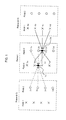
- a pel at line 1e is derived by filtering the pels at lines 1 b, 1c, 2a, 2b, 2c, 3a, 3b, 3c.
- a pel at line 2e is derived by filtering the pels at lines 2b, 2c, 1 b, 1c, 1d, 4b, 4c, 4d.
- the weights for filtering the lines in the adjacent fields are always summed to zero. It is important to note that this method involves a three-field aperture filtering which extends until the neighboring frames in the display order.
- a bidirectionally predicted picture is coded by referring to both past and future pictures in the display order.
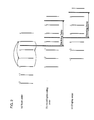
- the encoding/decoding order of a single layer system is illustrated in FIG. 2 in which the position of the frames, each consists of two fields, is plotted against time.
- frames #1 and #2 are predicted from frames #0 and #3. Therefore, frame #3 has to be coded first before coding frames #1 and #2, as depicted in case (b) in FIG. 2.
- the re-ordering of the input images demands four frame memories for storing the input images and incurs a three-frame delay between the input and output of the encoder.
- the reconstructed images have to be re-ordered back to the original order for display, which incurs another three-frame delay. This is shown in case (c) in FIG. 2.
- this bidirectional prediction scheme is applied to the two-layer encoding/decoding system which adopts the three-field aperture interpolation method for up-and down-conversion, the frame memories and delay will at least become double. The reason comes from the fact that compatible predictors from the low layer have to be re-ordered back to the display order before the three-field aperture interpolation is applied to up- convert the predictors to HDTV resolution.
- the number of frame memories and delay involved wi II further grow as the number of layers increases.
- An object of the present invention is to provide an efficient method for up- and down-conversion of interlaced images which is suitable for layered coding in the sense that the number of frame memories and delay involved are minimized to the level of a single layer system.
- the method is also capable of producing pictures with quality not worse than the three-field aperture method.
- a spatio-temporal interpolation is restricted within a frame where the interpolation of one field in a frame is derived from the opposite field in the same frame.
- an interlaced image which consists of a first and a second field is scaled according to the following steps.
- the first field is converted to a first progressive image in such a manner that an interpolated line in the first field is formed by an weighted average of two or more adjacent lines in the first field plus an weighted average of two or more adjacent lines in the second field where one of the lines in the second field is co-sited with the interpolated line in the first field.
- the second field is converted to a second progressive image in such a manner that an interpolated line in the second field is formed by an weighted average of two or more adjacent lines in the second field plus an weighted average of two or more adjacent lines in the first field where one of the lines in the first field is co-sited with the interpolated line in the second field.
- the first and second progressive images are then resampled vertically according to a predetermined resampling ratio m/n, where m and n are integers with n indicating the number of output samples out of m input samples.
- the weights for averaging the lines in the second field are summed to zero and when interpolating the second field, the weights for averaging the lines in the first field are also summed to zero.
- the first and second progressive images are filtered to a predetermined bandwidth prior to resampling.
- FIG. 3 illustrates a diagram showing a method of deriving a progressive image from an interlaced video signal in accordance with the present invention.
- the vertical position of each line is plotted vertically against time horizontally.
- fields 1 and 2 constitute the same frame.
- a pel in field 1 can be interpolated in the following manner: where w1, w2, ... , w5 are weights of a desired filter characteristic.
- the weights for field 2 satisfy the following condition:
- An example set of the weights may be as follows:
- a pel in field 2e can be interpolated in the similar manner as follows: where weights w1', w2', ... , w5' may have the same values as w1, w2, ... , w5, respectively, or other values characterizing a different filter response. Complex filters with more weights can be adopted for better performance.
- the two fields can be interpolated by spatio-temporal filtering without referring to fields from other frames.
- FIG. 4 A block diagram of a preferred embodi ment of an interpolator in accordance with the present invention is shown in FIG. 4.
- This interpolator 12 is constituted by a transversal fitter with switches 18 and 19 at the output ends, enabling alternative interpolation of fields 1 and 2.
- the example shows a five-tap filter constituted by buffers 15a-15d for delay, multiplying circuits 16a-16e for weighting and adders 17a-17d, but may be extended at needs.
- the input pels are fed through an input terminal 10. For consistency with FIG. 3, let the input pels be 2a, 1 b, 2b, 1 c, 2c, 1d and are fed into the interpolator in the given order at 0 second.
- Pel 1 b is outputted to an output terminal 22 which is connected to a frame memory #1 (FM#1) 220.
- the interpolated pel 2e is stored in the buffer 15e and delayed by 2 ⁇ seconds.
- the switch 18 is connected to the terminal 21a and the switch 19 is connected to the terminal 20b.
- pel 2b is outputted to through the output terminal 23 to the frame memory#2 and pel 1e is outputted through the output terminal 22 to the frame memory #1.
- pel lc is outputted to the frame memory #1 and pel 2e is outputted to the frame memory #2, and so on.
- an interpolated image of field 1 is stored in the frame memory #1 while an interpolated image of field 2 is stored in the frame memory #2.
- Fields 1 and 2 therefore, can be interpolated alternatively by using only one transversal filter.
- the interpolator can also be used for interpolating images horizontally as well as performing low/high pass filtering by fixing the switches 18 and 19 to appropriate output terminals and setting the weights to appropriate values.
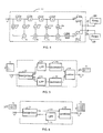
- FIG. 5 A block diagram of a preferred embodiment of a vertical down-converter in accordance with the present invention is shown in FIG. 5.
- An interlaced image, or a portion of the image, of size x times y is fed through an input terminal 10.
- Each field of the input image is interpolated in an interpolator 12 which may be the same as the interpolator described above.
- the interpolated images are then fed into low pass filters (LPF) 13a and 13b respectively for limiting the bandwidth of the signals.
- LPF low pass filters
- the fi Itered images are subsampled in decimators 14a and 14b, respectively, according to a predetermined resampling ratio m/n, where m and n are integers with n indicating the number of output samples out of m input samples.
- m/n may be 2/1, which implies that every other lines of the input image be outputted.
- the lines of the resampled images are then merged alternately by a combiner 24 to produce a vertically down-converted interlaced image of size x times y/2 at an outputterminal11.
- the vertically down-converted image may be subsequently fed into a horizontal down-converter.
- the original image may be horizontally down-converted before down-converting vertically.
- FIG. 6 is a block diagram of a preferred embodiment of a vertical up-converter in accordance with the present invention.
- An interlaced image, or a portion of the image, of sizextimes y/2 is fed through an input terminal 30.
- Each field of the input image is interpolated in an interpolator 32 which may be the same as the interpolator depicted in FIG. 4.
- Outputs of the interpolator 32 are progressive images of fields 1 and 2.
- One of the progressive images, usually field 1 is fed directly via a line 33 to a combiner 36.
- the other progressive image, usually field 2 is filtered by a low pass filter (LPF) 35 for shifting the lines of field 2 to the correct phase.
- LPF low pass filter
- the combiner 36 merges the lines of the two progressive images to produce an interlaced image of size x times y at an output terminal 31.
- the example in FIG. 6 assumed an input image which has been horizontally interpolated. Alternatively, the horizontal interpolation may be carried out after the vertical interpolation.
- FIG. 7 A block diagram of a preferred embodiment of a two-layer encoding apparatus utilizing the down-converter and up-converter in accordance with the present invention is shown in FIG. 7.
- the description will be concentrated on, but not limited to, HDTV and SDTV signals. Video signals of other resolution are equally applicable.
- An original interlaced HDTV picture inputted through an input terminal 40 is fed through a line 1000 into a down-converter 43 where it is down-converted in both horizontal and vertical directions.
- the vertical down-converter shown in FIG. 5 may be used in the down-converter 43.
- the down-converted interlaced picture is fed through a line 1001 into a first encoder 45 where it is divided into a plurality of blocks each containing a matrix of pixel data.
- each block is of size 8 x 8 pixels.
- a subtractor 57 receives a current block at one input thereof and a predicted block derived from one or more previously coded pictures at the other input thereof and produces a difference signal between the current block and the predicted block.
- An output of the subtractor 57 i.e., the difference signal, is then transformed in a transformation circuit (T) 58 and quantized by a quantizer (Q) 59.
- the transformation circuit 58 may perform one of the discrete cosine transform (DCT), the HADAMARD transform and the HAAR transform, which are most widely used.
- the quantized data and other side information are combined to produce a low layer data stream which is outputted through a line 1004 and an output terminal 42.
- the quantized data is fed to a first local decoder 46.
- the quantized data is dequantized by a dequantizer (IQ) 60 and inverse transformed by an inverse transformation circuit (IT) 61.
- IQ dequantizer
- IT inverse transformation circuit
- the predicted block is added back to the decompressed data from the inverse transformation circuit 61 to produce a reconstructed block.
- the reconstructed block is sent to an up-converter 44 via a line 1003.
- the up-converter 44 the reconstructed block is up-converted both horizontally and vertically.
- the up-converter 44 may be used in the up-converter 44.
- the up-converted block is used as a spatial predictorfor encoding the original block at HDTV resolution.
- Reconstructed blocks from the adder 62 are stored in a set of frame memories (P) 63.
- a reconstructed block is retrieved responsive to some motion signals as a predictor for subsequent encoding, which is fed to the subtractor 57 via a line 1002 and to the adder 62.
- the original interlaced HDTV picture is fed also into a second encoder 47 via a line 1005 and divided into a plurality of blocks.
- a difference signal is created by a subtractor49 from the current block and a predicted block, transformed by a transformation circuit (T) 50, and quantized by a quantizer (Q) 51 similarly to the processing in the first encoder 46.
- the quantized data and other side information are combined to produce a high layer data stream which is outputted through a line 1007 and an output terminal 41.
- the quantized data from the second encoder 47 are dequantized by a dequantizer (IQ) 52 and inverse transformed by an inverse transformation circuit (IT) 53.
- IQ dequantizer
- IT inverse transformation circuit
- the predicted block is added back to the decompressed data from the inverse transformation circuit 53 to produce a reconstructed block.
- Reconstructed blocks from the adder 54 are stored in a set of frame memories (P) 55.
- a reconstructed block is retrieved responsive to some motion signals as a temporal predictor for the subsequent encoding.
- a temporal predictor block retrieved from the set of frame memories 55 and a spatial predictor from the up-converter 44 are averaged at an averaging circuit (TS) 56 to produce a spatio-temporal predictor.
- the spatio-temporal predictor is sent via a line 1006 to the subtractor 49 to be subtracted from the current block and to the adder 54 to be added to the decompressed data from the inverse transformation circuit 53.
- An optimum set may be selected adaptively according to a predetermined criterion such as least mean square. The optimum weights are transmitted in the high layer data stream
- FIG. 8 A preferred embodiment of a corresponding decoding apparatus according to the present invention is shown in FIG. 8.
- the low layer data stream is fed into a first decoder 74 through an input terminal 70.
- the low layer data stream is dequantized by a dequantizer (IQ) 77 and inverse transformed by an inverse transformation circuit (IT) 78.
- IQ dequantizer
- IT inverse transformation circuit
- a predicted block retrieved from a set of frame memories (P) 80 as specified in the low layer data stream is added to the inverse transformed block to form a reconstructed block which is outputted from an output terminal 72.
- Reconstructed blocks from the adder 79 are stored in the set of frame memories (P) 80.
- the reconstructed block is also sent to an up-converter 76 where it is up-converted both horizontally and vertically.
- the vertical up-converter shown in FIG. 6 may be used in the up-converter 76.
- the up-converted block is used as a spatial predictor for decoding the high layer data stream.
- a reconstructed block is retrieved as indicated in the low layer data stream as a predictor for subsequent decoding.
- the high layer data stream is fed into a second decoder 75 through an input terminal 71.
- the high layer data stream is dequantized by a dequantizer (IQ) 81 and inverse transformed by an inverse transformation circuit (IT) 82.
- IQ dequantizer
- IT inverse transformation circuit
- a spatio-temporal predictor is derived from a temporal predictor retrieved from a set of frame memories (P) 84 and a spatial predictor from the up-converter 76, as specified in the high layer data stream.
- the spatio-temporal predictor is added to the inverse transformed block at an adder 83 to form a reconstructed block which is outputted from an output terminal 73. Reconstructed blocks from the adder 83 are stored in the set of frame memories (P) 84.
Abstract
Description
- The present invention relates to apparatuses for encoding and decoding of scalable digital video signals, and more particularly to a method of scaling of interlaced images for compatible encoding and decoding of video signals of multiple scanning standards.
- Numerous picture bit rate reduction coding schemes are known for compressing digitized video signals for transmission and storage at a reduced bit rate. Activities for developing these techniques are widely under progress. International standards have been created, while some are still under development, by organizations like CCITT and ISO.
- New coding schemes are required to maintain compatibility with existing ones while including some degree of scalability where the reconstructed video signals can have a multiplicity of spatial resolutions. When a new standard decoder is able to decode pictures from the signal of an existing standard encoder, the scheme is known to be forward compatible. On the other hand, when an existing standard decoder is able to decode pictures from signal of a new standard encoder, the new scheme is known to be backward compatible. The demand to satisfy both the forward and backward compatibility can be achieved by the layered coding.
- An encoding system for layered coding essentially consists of multiple layers of encoders coupled with each other. For simplicity, the description here- afterwill be concentrated on, but not limited to, a two-layer system where the low layer processes the standard TV video signals (SDTV) while the high layer processes the high definition video signals (HDTV). In an alternative system, the low and high layers may be assigned to process low definition video signals (LDTV) and SDTV signals, respectively. The encoding system receives a sequence of HDTV images which are down-converted to SDTV resolution. The low layer encoder compresses and encodes the down-converted images to produce a low layer data stream. The compressed SDTV signals are locally decoded for use as predictors for the high layer encoder and subsequent encoding process at the same layer. At the same time, the high layer encoder compresses and encodes the original HDTV images to produce a high layer data stream. Similarly, the compressed HDTV signals are locally decoded for use as predictors for subsequent encoding process at the same layer. Hence, there are two predictors for the high layer encoder: one comes from the same (high) layer while the other comes from the low layer. The predictor from the same (high) layer, hereafter referred to as "temporal predictor", is a past or future decompressed picture in the display order. The predictor from the low layer, hereafter referred to as "compatible predictor", is spatially up-converted to HDTV resolution and used for compatible prediction. Both the temporal and compatible predictors may be used separately or together in a weighted average form. Finally, the low and high layer data streams are multiplexed for transmission and/or storage.
- A corresponding decoding system of a two-layer encoding system essentially consists of a low layer decoder and a high layer decoder. The transmitted signal is first demultiplexed to the low and high layer data streams. The low layer data stream is decompressed and decoded by the low layer decoder to produce reconstructed SDTV images. These reconstructed SDTV images are up-converted to HDTV resolution and used as compatible predictors for the high layer decoder. At the same time, the high layer data stream is decompressed and decoded by the high layer decoder, based on the temporal and compatible predictors, to reconstruct the HDTV images. The decoding system can, therefore, produce images at SDTV and HDTV resolutions, allowing some degree of scalability.
- Efficient up- and down-conversions are crucial to the layered coding described above, especially when both the SDTV and HDTV images are interlaced. Early technologies adopted intrafield conversion methods where all lines in an output field were derived from the lines in only one field of the input. For down-conversion, each field of the input interlaced frames is filtered and down-sampled independently, and for up-conversion, each field of the input interlaced frames is interpolated vertically from two or more lines in the same field. It is well recognized that intra- field down-conversion is inadequate for deriving interlaced lower resolution images from higher resolution interlaced source. The problem becomes even worse when the down-converted images are coded and up-converted, based on an intra-field method, and used as compatible prediction for layered coding.
- Further improvements could be achieved by employing temporal interpolation in addition to vertical interpolation, i.e., by using lines from more than one input field in deriving the lines in an output field. Temporal interpolation improves vertical definition on stationary images, but causes very noticeable impairment for scenes with fast movements. One way for solving the problem is to use adaptive system in which the temporal interpolation is used for stationary and very slowly moving scenes and the vertical interpolation is used for scenes with faster movements. An example of the adaptive method could be found in UK Patent GB 2184628.
- It was later realized that a non-adaptive spatio- temporal interpolation could give the similar performance as the adaptive system but with less complexity because any movement detector circuitry is not needed. The details of the non-adaptive spatiotemporal interpolation is found in Devereux, V.G, "Standards conversion between 1250/50 and 625/50 TV systems", IBC 92 paper. According to this method, interpolation of one field is derived from a plurality of lines in the same field and those in the adjacent fields which come immediately before and after the target field. This is illustrated in FIG. 1 in which the vertical position of lines is plotted vertically against time horizontally. In the diagram, a pel at line 1e is derived by filtering the pels at
lines line 2e is derived by filtering the pels atlines - A coding scheme which adopts "bi-directional prediction", however, does not process the images according to the display order. A bidirectionally predicted picture is coded by referring to both past and future pictures in the display order. The encoding/decoding order of a single layer system is illustrated in FIG. 2 in which the position of the frames, each consists of two fields, is plotted against time. In case (a) in FIG. 2,
frames # 1 and #2 are predicted from frames #0 and #3. Therefore,frame # 3 has to be coded first beforecoding frames # 1 and #2, as depicted in case (b) in FIG. 2. The re-ordering of the input images demands four frame memories for storing the input images and incurs a three-frame delay between the input and output of the encoder. At the decoder, the reconstructed images have to be re-ordered back to the original order for display, which incurs another three-frame delay. This is shown in case (c) in FIG. 2. When this bidirectional prediction scheme is applied to the two-layer encoding/decoding system which adopts the three-field aperture interpolation method for up-and down-conversion, the frame memories and delay will at least become double. The reason comes from the fact that compatible predictors from the low layer have to be re-ordered back to the display order before the three-field aperture interpolation is applied to up- convert the predictors to HDTV resolution. The number of frame memories and delay involved wi II further grow as the number of layers increases. - An object of the present invention is to provide an efficient method for up- and down-conversion of interlaced images which is suitable for layered coding in the sense that the number of frame memories and delay involved are minimized to the level of a single layer system. The method is also capable of producing pictures with quality not worse than the three-field aperture method.
- According to the present invention, a spatio-temporal interpolation is restricted within a frame where the interpolation of one field in a frame is derived from the opposite field in the same frame. This eliminates the necessity of re-ordering the compatible predictors from the low layer back to the display order when up-converting the predictors to higher resolution. The number of frame memories and delay involved, thus, can be reduced drastically. At minimum, the system only needs the same number of frame memories and incurs the same delay time as a single layer system. When applied to normal pictures, the quality of the converted pictures was discovered to be not worse than that of the three-field aperture method.
- More specifically, an interlaced image which consists of a first and a second field is scaled according to the following steps. The first field is converted to a first progressive image in such a manner that an interpolated line in the first field is formed by an weighted average of two or more adjacent lines in the first field plus an weighted average of two or more adjacent lines in the second field where one of the lines in the second field is co-sited with the interpolated line in the first field. Similarly, the second field is converted to a second progressive image in such a manner that an interpolated line in the second field is formed by an weighted average of two or more adjacent lines in the second field plus an weighted average of two or more adjacent lines in the first field where one of the lines in the first field is co-sited with the interpolated line in the second field. The first and second progressive images are then resampled vertically according to a predetermined resampling ratio m/n, where m and n are integers with n indicating the number of output samples out of m input samples.
- In a preferred manner, when interpolating the first field, the weights for averaging the lines in the second field are summed to zero and when interpolating the second field, the weights for averaging the lines in the first field are also summed to zero. In another preferred manner, the first and second progressive images are filtered to a predetermined bandwidth prior to resampling.
- The features and advantages of the invention would be gathered from the following non-limitative, illustrative description made with reference to the attached drawings.
-
- FIG. 1 illustrates a prior art for deriving a progressive image from an interlaced video signal by means of a diagram showing vertical positions plotted against time.
- FIG. 2 illustrates input order, encoding/decoding order and display order of a reconstructed image.
- FIG. 3 illustrates a method of deriving a progressive image from an interlaced video signal in accordance with the present invention.
- FIG. 4 is a block diagram of an embodiment for deriving a progressive image from an interlaced video signal in accordance with the present invention.
- FIG. 5 is a block diagram of an embodiment of a vertical down-converter in accordance with the present invention.
- FIG. 6 is a block diagram of an embodiment of a vertical up-converter in accordance with the present invention.
- FIG. 7 is a block diagram of an embodiment of an encoding apparatus utilizing the down-converter and up-converter in accordance with the present invention.
- FIG. 8 is a block diagram of an embodiment of a decoding apparatus utilizing the up-converter in accordance with the present invention.
- FIG. 3 illustrates a diagram showing a method of deriving a progressive image from an interlaced video signal in accordance with the present invention. In the diagram, the vertical position of each line is plotted vertically against time horizontally. It is important to note that
fields field 1, for example 1e, can be interpolated in the following manner:
field 2 satisfy the following condition:
- An example set of the weights may be as follows:


- Next, a pel in
field 2, for example 2e, can be interpolated in the similar manner as follows:
- A block diagram of a preferred embodi ment of an interpolator in accordance with the present invention is shown in FIG. 4. This
interpolator 12 is constituted by a transversal fitter withswitches 18 and 19 at the output ends, enabling alternative interpolation offields buffers 15a-15d for delay, multiplying circuits 16a-16e for weighting andadders 17a-17d, but may be extended at needs. The input pels are fed through an input terminal 10. For consistency with FIG. 3, let the input pels be 2a, 1 b, 2b, 1 c, 2c, 1d and are fed into the interpolator in the given order at 0 second. Each pel moves across the filter every τ seconds, is multiplied by a corresponding weight (w1, w2, ... , w5) and summed by a corresponding adder (17a, 17b, ... , 17d). At 4τ second, let the switch 18 be connected to its terminal 21 a and theswitch 19 be connected to its terminal 20b. At this instant,pels 2a and le (interpolated pel in FIG. 3) emerge from the filter.Pel 2a is outputted to anoutput terminal 23 which is connected to a frame memory #2 (FM#2) 230. The interpolated pel le is stored in abuffer 15e and delayed by 2τ seconds. At 5i second, the switch 18 is connected to its terminal 20a and theswitch 19 is connected to its terminal 21 b. At this instant, pels 1 b and 2e (interpolated pel in FIG. 3) emerge from the fi I-ter. Pel 1 b is outputted to anoutput terminal 22 which is connected to a frame memory #1 (FM#1) 220. The interpolatedpel 2e is stored in thebuffer 15e and delayed by 2τ seconds. At 6τ second, the switch 18 is connected to the terminal 21a and theswitch 19 is connected to the terminal 20b. At this instant, pel 2b is outputted to through theoutput terminal 23 to theframe memory# 2 and pel 1e is outputted through theoutput terminal 22 to theframe memory # 1. At the next instant, pel lc is outputted to theframe memory # 1 and pel 2e is outputted to theframe memory # 2, and so on. In this manner, an interpolated image offield 1 is stored in theframe memory # 1 while an interpolated image offield 2 is stored in theframe memory # 2.Fields switches 18 and 19 to appropriate output terminals and setting the weights to appropriate values. - A block diagram of a preferred embodiment of a vertical down-converter in accordance with the present invention is shown in FIG. 5. An interlaced image, or a portion of the image, of size x times y is fed through an input terminal 10. Each field of the input image is interpolated in an
interpolator 12 which may be the same as the interpolator described above. The interpolated images are then fed into low pass filters (LPF) 13a and 13b respectively for limiting the bandwidth of the signals. Next, the fi Itered images are subsampled indecimators combiner 24 to produce a vertically down-converted interlaced image of size x times y/2 at an outputterminal11. The vertically down-converted image may be subsequently fed into a horizontal down-converter. Alternatively, the original image may be horizontally down-converted before down-converting vertically. - FIG. 6 is a block diagram of a preferred embodiment of a vertical up-converter in accordance with the present invention. An interlaced image, or a portion of the image, of sizextimes y/2 is fed through an input terminal 30. Each field of the input image is interpolated in an
interpolator 32 which may be the same as the interpolator depicted in FIG. 4. Outputs of theinterpolator 32 are progressive images offields field 1, is fed directly via aline 33 to acombiner 36. The other progressive image, usuallyfield 2, is filtered by a low pass filter (LPF) 35 for shifting the lines offield 2 to the correct phase. Finally, thecombiner 36 merges the lines of the two progressive images to produce an interlaced image of size x times y at anoutput terminal 31. The example in FIG. 6 assumed an input image which has been horizontally interpolated. Alternatively, the horizontal interpolation may be carried out after the vertical interpolation. - A block diagram of a preferred embodiment of a two-layer encoding apparatus utilizing the down-converter and up-converter in accordance with the present invention is shown in FIG. 7. The description will be concentrated on, but not limited to, HDTV and SDTV signals. Video signals of other resolution are equally applicable. An original interlaced HDTV picture inputted through an
input terminal 40 is fed through aline 1000 into a down-converter 43 where it is down-converted in both horizontal and vertical directions. The vertical down-converter shown in FIG. 5 may be used in the down-converter 43. The down-converted interlaced picture is fed through aline 1001 into afirst encoder 45 where it is divided into a plurality of blocks each containing a matrix of pixel data. In the present embodiment, each block is of size 8 x 8 pixels. In thefirst encoder 45, asubtractor 57 receives a current block at one input thereof and a predicted block derived from one or more previously coded pictures at the other input thereof and produces a difference signal between the current block and the predicted block. An output of thesubtractor 57, i.e., the difference signal, is then transformed in a transformation circuit (T) 58 and quantized by a quantizer (Q) 59. Thetransformation circuit 58 may perform one of the discrete cosine transform (DCT), the HADAMARD transform and the HAAR transform, which are most widely used. The quantized data and other side information are combined to produce a low layer data stream which is outputted through aline 1004 and anoutput terminal 42. At the same time, the quantized data is fed to a first local decoder 46. In the first local decoder 46, the quantized data is dequantized by a dequantizer (IQ) 60 and inverse transformed by an inverse transformation circuit (IT) 61. At anadder 62, the predicted block is added back to the decompressed data from the inverse transformation circuit 61 to produce a reconstructed block. The reconstructed block is sent to an up-converter 44 via aline 1003. In the up-converter 44, the reconstructed block is up-converted both horizontally and vertically. The vertical up-converter shown in FIG. 6 may be used in the up-converter 44. The up-converted block is used as a spatial predictorfor encoding the original block at HDTV resolution. Reconstructed blocks from theadder 62 are stored in a set of frame memories (P) 63. A reconstructed block is retrieved responsive to some motion signals as a predictor for subsequent encoding, which is fed to thesubtractor 57 via aline 1002 and to theadder 62. - At the same time, the original interlaced HDTV picture is fed also into a second encoder 47 via a
line 1005 and divided into a plurality of blocks. A difference signal is created by a subtractor49 from the current block and a predicted block, transformed by a transformation circuit (T) 50, and quantized by a quantizer (Q) 51 similarly to the processing in the first encoder 46. The quantized data and other side information are combined to produce a high layer data stream which is outputted through a line 1007 and anoutput terminal 41. In a secondlocal decoder 48, the quantized data from the second encoder 47 are dequantized by a dequantizer (IQ) 52 and inverse transformed by an inverse transformation circuit (IT) 53. At anadder 54, the predicted block is added back to the decompressed data from theinverse transformation circuit 53 to produce a reconstructed block. Reconstructed blocks from theadder 54 are stored in a set of frame memories (P) 55. A reconstructed block is retrieved responsive to some motion signals as a temporal predictor for the subsequent encoding. A temporal predictor block retrieved from the set offrame memories 55 and a spatial predictor from the up-converter 44 are averaged at an averaging circuit (TS) 56 to produce a spatio-temporal predictor. The spatio-temporal predictor is sent via aline 1006 to thesubtractor 49 to be subtracted from the current block and to theadder 54 to be added to the decompressed data from theinverse transformation circuit 53. There may exist several candidate sets of weights for averaging the spatio-temporal predictor. An optimum set may be selected adaptively according to a predetermined criterion such as least mean square. The optimum weights are transmitted in the high layer data stream. - A preferred embodiment of a corresponding decoding apparatus according to the present invention is shown in FIG. 8. The low layer data stream is fed into a
first decoder 74 through aninput terminal 70. The low layer data stream is dequantized by a dequantizer (IQ) 77 and inverse transformed by an inverse transformation circuit (IT) 78. At anadder 79, a predicted block retrieved from a set of frame memories (P) 80 as specified in the low layer data stream is added to the inverse transformed block to form a reconstructed block which is outputted from anoutput terminal 72. Reconstructed blocks from theadder 79 are stored in the set of frame memories (P) 80. The reconstructed block is also sent to an up-converter 76 where it is up-converted both horizontally and vertically. The vertical up-converter shown in FIG. 6 may be used in the up-converter 76. The up-converted block is used as a spatial predictor for decoding the high layer data stream. A reconstructed block is retrieved as indicated in the low layer data stream as a predictor for subsequent decoding. - At the same time, the high layer data stream is fed into a
second decoder 75 through an input terminal 71. The high layer data stream is dequantized by a dequantizer (IQ) 81 and inverse transformed by an inverse transformation circuit (IT) 82. At an averagingcircuit 85, a spatio-temporal predictor is derived from a temporal predictor retrieved from a set of frame memories (P) 84 and a spatial predictor from the up-converter 76, as specified in the high layer data stream. The spatio-temporal predictor is added to the inverse transformed block at anadder 83 to form a reconstructed block which is outputted from anoutput terminal 73. Reconstructed blocks from theadder 83 are stored in the set of frame memories (P) 84. - Although the invention has been described in connection with preferred embodiments thereof, those skilled in the art would appreciate that numerous modifications and adaptations may be made thereto without departing from the spirit and scope of the invention as set forth in the appended claims.
Claims (8)
Applications Claiming Priority (3)
| Application Number | Priority Date | Filing Date | Title |
|---|---|---|---|
| JP8969/93 | 1993-01-22 | ||
| JP896993 | 1993-01-22 | ||
| JP896993A JP2962083B2 (en) | 1993-01-22 | 1993-01-22 | Resolution conversion method, resolution conversion device, image encoding device, image decoding device |
Publications (3)
| Publication Number | Publication Date |
|---|---|
| EP0608092A2 true EP0608092A2 (en) | 1994-07-27 |
| EP0608092A3 EP0608092A3 (en) | 1996-05-15 |
| EP0608092B1 EP0608092B1 (en) | 2000-04-05 |
Family
ID=11707517
Family Applications (1)
| Application Number | Title | Priority Date | Filing Date |
|---|---|---|---|
| EP19940300306 Expired - Lifetime EP0608092B1 (en) | 1993-01-22 | 1994-01-17 | Apparatuses and methods for scalable encoding and decoding of video signalss |
Country Status (4)
| Country | Link |
|---|---|
| US (1) | US5446498A (en) |
| EP (1) | EP0608092B1 (en) |
| JP (1) | JP2962083B2 (en) |
| DE (1) | DE69423798T2 (en) |
Cited By (9)
| Publication number | Priority date | Publication date | Assignee | Title |
|---|---|---|---|---|
| EP0836327A2 (en) * | 1996-10-11 | 1998-04-15 | Victor Company Of Japan, Ltd. | Video coding/decoding apparatus and method |
| EP0921677A2 (en) * | 1997-12-04 | 1999-06-09 | Victor Company Of Japan, Limited | Image pickup apparatus equipped with contour compensation circuit, image output circuit and electronic zoom circuit |
| GB2348067A (en) * | 1999-03-19 | 2000-09-20 | Mitsubishi Electric Inf Tech | Encoding an interlaced video signal into a progressive signal using an apparatus which also provides for reverse decoding |
| EP1163797A1 (en) * | 1998-12-18 | 2001-12-19 | Oplus Technologies Ltd. | Method of de-interlacing video signals using a mixed mode spatial and temporal approximation technique |
| US6538694B1 (en) | 1997-12-04 | 2003-03-25 | Victor Company Of Japan, Limited | Image pickup apparatus equipped with compatible-with-zooming type contour compensation circuit, compatible-with-image-pickup-conditions type image output circuit, and compatible-with-all-pixel-readout-system-solid-image-pickup-element type electronic zoom circuit |
| WO2006125052A2 (en) * | 2005-05-18 | 2006-11-23 | Scientific-Atlanta, Inc. | Higher picture rate hd encoding and transmission with legacy hd backward compatibility |
| EP1955549A1 (en) * | 2005-11-18 | 2008-08-13 | Sharp Kabushiki Kaisha | Methods and systems for picture resampling |
| US8457214B2 (en) | 2007-09-10 | 2013-06-04 | Cisco Technology, Inc. | Video compositing of an arbitrary number of source streams using flexible macroblock ordering |
| US10567703B2 (en) | 2017-06-05 | 2020-02-18 | Cisco Technology, Inc. | High frame rate video compatible with existing receivers and amenable to video decoder implementation |
Families Citing this family (26)
| Publication number | Priority date | Publication date | Assignee | Title |
|---|---|---|---|---|
| DE69535228T2 (en) * | 1994-06-08 | 2007-09-13 | Matsushita Electric Industrial Co., Ltd., Kadoma | Image conversion device |
| JP3634410B2 (en) * | 1994-10-18 | 2005-03-30 | キヤノン株式会社 | Image processing system, image processing apparatus and method |
| KR100420744B1 (en) * | 1995-05-12 | 2004-09-04 | 코닌클리케 필립스 일렉트로닉스 엔.브이. | Image display apparatus with line number conversion |
| US5850207A (en) * | 1995-11-22 | 1998-12-15 | Cirrus Logic, Inc. | Method and apparatus for minimizing effects of slope overload condition when using differential pulse code modulation scheme |
| US5825927A (en) * | 1996-01-16 | 1998-10-20 | Hitachi America, Ltd. | Methods and apparatus for encoding video data in a manner that is well suited for decoding by regular or downconverting decoders |
| US6957350B1 (en) | 1996-01-30 | 2005-10-18 | Dolby Laboratories Licensing Corporation | Encrypted and watermarked temporal and resolution layering in advanced television |
| US5768537A (en) * | 1996-02-22 | 1998-06-16 | International Business Machines Corporation | Scalable MPEG2 compliant video encoder |
| US6166772A (en) * | 1997-04-01 | 2000-12-26 | Compaq Computer Corporation | Method and apparatus for display of interlaced images on non-interlaced display |
| US6275616B1 (en) * | 1997-09-12 | 2001-08-14 | Samsung Electronics Co., Ltd. | Method and apparatus for converting a high definition image to a relatively lower definition image using wavelet transforms |
| US6873368B1 (en) | 1997-12-23 | 2005-03-29 | Thomson Licensing Sa. | Low noise encoding and decoding method |
| EP0926899A3 (en) | 1997-12-25 | 1999-12-15 | SANYO ELECTRIC Co., Ltd. | An apparatus and process for decoding motion pictures |
| JP3820026B2 (en) * | 1998-03-09 | 2006-09-13 | パイオニア株式会社 | Scan line interpolation method |
| US6266092B1 (en) * | 1998-05-12 | 2001-07-24 | Genesis Microchip Inc. | Method and apparatus for video line multiplication with enhanced sharpness |
| US6704463B1 (en) * | 1998-11-10 | 2004-03-09 | Sony Corporation | Interpolation/decimation apparatus, interpolation/decimation method and image display apparatus |
| US6765966B2 (en) * | 2000-12-19 | 2004-07-20 | General Instrument Corporation | Methods and apparatus for re-encoding a high definition television signal to create a standard definition television signal |
| US8374237B2 (en) | 2001-03-02 | 2013-02-12 | Dolby Laboratories Licensing Corporation | High precision encoding and decoding of video images |
| US6870543B1 (en) * | 2001-06-06 | 2005-03-22 | Microsoft Corporation | Reducing fill and improving quality of interlaced displays using multi-sampling |
| US7266150B2 (en) | 2001-07-11 | 2007-09-04 | Dolby Laboratories, Inc. | Interpolation of video compression frames |
| US8111754B1 (en) | 2001-07-11 | 2012-02-07 | Dolby Laboratories Licensing Corporation | Interpolation of video compression frames |
| US20030112863A1 (en) | 2001-07-12 | 2003-06-19 | Demos Gary A. | Method and system for improving compressed image chroma information |
| US6784942B2 (en) * | 2001-10-05 | 2004-08-31 | Genesis Microchip, Inc. | Motion adaptive de-interlacing method and apparatus |
| DE102004016350A1 (en) * | 2004-04-02 | 2005-10-27 | Micronas Gmbh | Method and device for interpolating a pixel of an intermediate line of a field |
| JP2006129069A (en) * | 2004-10-28 | 2006-05-18 | Canon Inc | Image pickup device and image pickup method |
| JP2007096604A (en) * | 2005-09-28 | 2007-04-12 | Toshiba Corp | Electronic equipment, video receiving device, and control method thereof |
| CN102113326A (en) | 2008-08-04 | 2011-06-29 | 杜比实验室特许公司 | Overlapped block disparity estimation and compensation architecture |
| JP6580831B2 (en) | 2015-01-22 | 2019-09-25 | 三星ディスプレイ株式會社Samsung Display Co.,Ltd. | Image processing apparatus, image processing method, and program |
Citations (4)
| Publication number | Priority date | Publication date | Assignee | Title |
|---|---|---|---|---|
| GB2184628A (en) * | 1983-12-13 | 1987-06-24 | British Broadcasting Corp | Video signal processing |
| EP0266079A2 (en) * | 1986-10-31 | 1988-05-04 | British Broadcasting Corporation | Interpolating lines of video signals |
| EP0484844A2 (en) * | 1990-11-05 | 1992-05-13 | THOMSON multimedia | Compatibility improvement apparatus |
| EP0502693A2 (en) * | 1991-03-04 | 1992-09-09 | Sony Corporation | Television receiver for EDTV |
Family Cites Families (3)
| Publication number | Priority date | Publication date | Assignee | Title |
|---|---|---|---|---|
| US5067016A (en) * | 1990-03-07 | 1991-11-19 | Industrial Technology Research Institute | Progressive scan system with field-offset sampling |
| JPH0693773B2 (en) * | 1992-04-27 | 1994-11-16 | 株式会社ハイコム | How to increase the number of scanning lines |
| JPH0693774B2 (en) * | 1992-04-27 | 1994-11-16 | 株式会社ハイコム | How to reduce the number of scanning lines |
-
1993
- 1993-01-22 JP JP896993A patent/JP2962083B2/en not_active Expired - Fee Related
-
1994
- 1994-01-17 DE DE1994623798 patent/DE69423798T2/en not_active Expired - Fee Related
- 1994-01-17 EP EP19940300306 patent/EP0608092B1/en not_active Expired - Lifetime
- 1994-01-24 US US08/185,244 patent/US5446498A/en not_active Expired - Fee Related
Patent Citations (4)
| Publication number | Priority date | Publication date | Assignee | Title |
|---|---|---|---|---|
| GB2184628A (en) * | 1983-12-13 | 1987-06-24 | British Broadcasting Corp | Video signal processing |
| EP0266079A2 (en) * | 1986-10-31 | 1988-05-04 | British Broadcasting Corporation | Interpolating lines of video signals |
| EP0484844A2 (en) * | 1990-11-05 | 1992-05-13 | THOMSON multimedia | Compatibility improvement apparatus |
| EP0502693A2 (en) * | 1991-03-04 | 1992-09-09 | Sony Corporation | Television receiver for EDTV |
Non-Patent Citations (2)
| Title |
|---|
| IEEE JOURNAL ON SELECTED AREAS IN COMMUNICATION, vol. 11, no. 1, January 1993, NEW YORK US, pages 146-151, XP000378006 DELOGNE ET AL.: "Compatible Coding of Digital Interlaced HDTV" * |
| SIGNAL PROCESSING IMAGE COMMUNICATION., vol. 5, no. 5/6, December 1993, AMSTERDAM NL, pages 445-462, XP000426716 MORRISON ET AL.: "A spatially layered hierarchical approach to video coding" * |
Cited By (18)
| Publication number | Priority date | Publication date | Assignee | Title |
|---|---|---|---|---|
| US6327306B1 (en) | 1996-10-11 | 2001-12-04 | Victor Company Of Japan, Ltd. | Interlaced moving image signal coding/decoding apparatus and method, and storage medium for storing coded interlaced moving image signal |
| EP0836327A2 (en) * | 1996-10-11 | 1998-04-15 | Victor Company Of Japan, Ltd. | Video coding/decoding apparatus and method |
| EP0836327A3 (en) * | 1996-10-11 | 2000-08-23 | Victor Company Of Japan, Ltd. | Video coding/decoding apparatus and method |
| US6538694B1 (en) | 1997-12-04 | 2003-03-25 | Victor Company Of Japan, Limited | Image pickup apparatus equipped with compatible-with-zooming type contour compensation circuit, compatible-with-image-pickup-conditions type image output circuit, and compatible-with-all-pixel-readout-system-solid-image-pickup-element type electronic zoom circuit |
| EP0921677A3 (en) * | 1997-12-04 | 2001-07-11 | Victor Company Of Japan, Limited | Image pickup apparatus equipped with contour compensation circuit, image output circuit and electronic zoom circuit |
| EP0921677A2 (en) * | 1997-12-04 | 1999-06-09 | Victor Company Of Japan, Limited | Image pickup apparatus equipped with contour compensation circuit, image output circuit and electronic zoom circuit |
| EP1163797A1 (en) * | 1998-12-18 | 2001-12-19 | Oplus Technologies Ltd. | Method of de-interlacing video signals using a mixed mode spatial and temporal approximation technique |
| EP1163797A4 (en) * | 1998-12-18 | 2005-08-17 | Oplus Technologies Ltd | Method of de-interlacing video signals using a mixed mode spatial and temporal approximation technique |
| GB2348067A (en) * | 1999-03-19 | 2000-09-20 | Mitsubishi Electric Inf Tech | Encoding an interlaced video signal into a progressive signal using an apparatus which also provides for reverse decoding |
| GB2348067B (en) * | 1999-03-19 | 2003-03-12 | Mitsubishi Electric Inf Tech | A method and a device for encoding and decoding of interlaced video signals by a codec for progressive video signals |
| WO2006125052A2 (en) * | 2005-05-18 | 2006-11-23 | Scientific-Atlanta, Inc. | Higher picture rate hd encoding and transmission with legacy hd backward compatibility |
| WO2006125052A3 (en) * | 2005-05-18 | 2007-01-04 | Scientific Atlanta | Higher picture rate hd encoding and transmission with legacy hd backward compatibility |
| US9729906B2 (en) | 2005-05-18 | 2017-08-08 | Cisco Technology, Inc. | Providing representations of a video program with multiple video streams having different stream types |
| EP1955549A1 (en) * | 2005-11-18 | 2008-08-13 | Sharp Kabushiki Kaisha | Methods and systems for picture resampling |
| EP1955549A4 (en) * | 2005-11-18 | 2011-02-16 | Sharp Kk | Methods and systems for picture resampling |
| US8457214B2 (en) | 2007-09-10 | 2013-06-04 | Cisco Technology, Inc. | Video compositing of an arbitrary number of source streams using flexible macroblock ordering |
| US8934553B2 (en) | 2007-09-10 | 2015-01-13 | Cisco Technology, Inc. | Creation of composite images from a plurality of source streams |
| US10567703B2 (en) | 2017-06-05 | 2020-02-18 | Cisco Technology, Inc. | High frame rate video compatible with existing receivers and amenable to video decoder implementation |
Also Published As
| Publication number | Publication date |
|---|---|
| JPH06225268A (en) | 1994-08-12 |
| EP0608092B1 (en) | 2000-04-05 |
| US5446498A (en) | 1995-08-29 |
| JP2962083B2 (en) | 1999-10-12 |
| DE69423798T2 (en) | 2000-08-03 |
| DE69423798D1 (en) | 2000-05-11 |
| EP0608092A3 (en) | 1996-05-15 |
Similar Documents
| Publication | Publication Date | Title |
|---|---|---|
| US5446498A (en) | Scaling interlaced images for encoding and decoding of digital video signals of multiple scanning standards | |
| US6990241B2 (en) | Circuit and method for decoding an encoded version of an image having a first resolution directly into a decoded version of the image having a second resolution | |
| US5742343A (en) | Scalable encoding and decoding of high-resolution progressive video | |
| US6584154B1 (en) | Moving-picture coding and decoding method and apparatus with reduced computational cost | |
| KR100289587B1 (en) | An image signal encoding method and an image signal encoding apparatus, an image signal decoding method and an image signal decoding apparatus, and an image signal recording medium | |
| EP0644695A2 (en) | Spatially scalable video encoding and decoding | |
| EP0396360A2 (en) | Apparatus for inter-frame predictive encoding of video signal | |
| EP0618729B1 (en) | Video-signal transmitting and receiving apparatus and method thereof | |
| US20010016010A1 (en) | Apparatus for receiving digital moving picture | |
| US5801777A (en) | Device and method for decoding digital video data | |
| JPH07212761A (en) | Hierarchical coder and hierarchical decoder | |
| KR100282307B1 (en) | Digital TV Receive Decoder Device | |
| US5422672A (en) | System comprisisng at least one encoder for coding a digital signal and at least one decoder for decoding a coded digital signal, and encoder and decoder for use in the system | |
| JP2000036963A (en) | Image coder, image coding method and image decoder | |
| US5457497A (en) | Method and apparatus for video signal bandwidth reduction with high quality compatible signal | |
| JPH06205397A (en) | Dynamic image coding device | |
| EP0944264B1 (en) | Apparatus and method of encoding/decoding moving picture and storage medium storing encoded moving picture | |
| JPH07107488A (en) | Moving picture encoding device | |
| KR0147777B1 (en) | Video-signal transmitting and receiving apparatus and method thereof | |
| KR100255777B1 (en) | Digital tv receiver decoder device | |
| JPH05236456A (en) | Method and device for encoding moving image | |
| Dubois et al. | Impact of scan conversion methods on the performance of scalable video coding | |
| JP3963184B2 (en) | Signal processing apparatus and signal processing method | |
| JPH04358485A (en) | Coder and picture coder | |
| JP2000023156A (en) | Image encoder, encoding method and image decoder |
Legal Events
| Date | Code | Title | Description |
|---|---|---|---|
| PUAI | Public reference made under article 153(3) epc to a published international application that has entered the european phase |
Free format text: ORIGINAL CODE: 0009012 |
|
| AK | Designated contracting states |
Kind code of ref document: A2 Designated state(s): DE FR GB IT |
|
| PUAL | Search report despatched |
Free format text: ORIGINAL CODE: 0009013 |
|
| AK | Designated contracting states |
Kind code of ref document: A3 Designated state(s): DE FR GB IT |
|
| 17P | Request for examination filed |
Effective date: 19961108 |
|
| 17Q | First examination report despatched |
Effective date: 19980707 |
|
| GRAG | Despatch of communication of intention to grant |
Free format text: ORIGINAL CODE: EPIDOS AGRA |
|
| GRAG | Despatch of communication of intention to grant |
Free format text: ORIGINAL CODE: EPIDOS AGRA |
|
| GRAH | Despatch of communication of intention to grant a patent |
Free format text: ORIGINAL CODE: EPIDOS IGRA |
|
| GRAH | Despatch of communication of intention to grant a patent |
Free format text: ORIGINAL CODE: EPIDOS IGRA |
|
| GRAA | (expected) grant |
Free format text: ORIGINAL CODE: 0009210 |
|
| AK | Designated contracting states |
Kind code of ref document: B1 Designated state(s): DE FR GB IT |
|
| ITF | It: translation for a ep patent filed |
Owner name: JACOBACCI & PERANI S.P.A. |
|
| REF | Corresponds to: |
Ref document number: 69423798 Country of ref document: DE Date of ref document: 20000511 |
|
| ET | Fr: translation filed | ||
| PLBE | No opposition filed within time limit |
Free format text: ORIGINAL CODE: 0009261 |
|
| STAA | Information on the status of an ep patent application or granted ep patent |
Free format text: STATUS: NO OPPOSITION FILED WITHIN TIME LIMIT |
|
| 26N | No opposition filed | ||
| REG | Reference to a national code |
Ref country code: GB Ref legal event code: IF02 |
|
| PGFP | Annual fee paid to national office [announced via postgrant information from national office to epo] |
Ref country code: DE Payment date: 20070111 Year of fee payment: 14 |
|
| PGFP | Annual fee paid to national office [announced via postgrant information from national office to epo] |
Ref country code: GB Payment date: 20070117 Year of fee payment: 14 |
|
| PGFP | Annual fee paid to national office [announced via postgrant information from national office to epo] |
Ref country code: IT Payment date: 20070608 Year of fee payment: 14 |
|
| PGFP | Annual fee paid to national office [announced via postgrant information from national office to epo] |
Ref country code: FR Payment date: 20070109 Year of fee payment: 14 |
|
| GBPC | Gb: european patent ceased through non-payment of renewal fee |
Effective date: 20080117 |
|
| PG25 | Lapsed in a contracting state [announced via postgrant information from national office to epo] |
Ref country code: DE Free format text: LAPSE BECAUSE OF NON-PAYMENT OF DUE FEES Effective date: 20080801 |
|
| REG | Reference to a national code |
Ref country code: FR Ref legal event code: ST Effective date: 20081029 |
|
| PG25 | Lapsed in a contracting state [announced via postgrant information from national office to epo] |
Ref country code: GB Free format text: LAPSE BECAUSE OF NON-PAYMENT OF DUE FEES Effective date: 20080117 |
|
| PG25 | Lapsed in a contracting state [announced via postgrant information from national office to epo] |
Ref country code: FR Free format text: LAPSE BECAUSE OF NON-PAYMENT OF DUE FEES Effective date: 20080131 |
|
| PG25 | Lapsed in a contracting state [announced via postgrant information from national office to epo] |
Ref country code: IT Free format text: LAPSE BECAUSE OF NON-PAYMENT OF DUE FEES Effective date: 20080117 |