EP0603365B1 - A hypodermic needle with protection device - Google Patents
A hypodermic needle with protection device Download PDFInfo
- Publication number
- EP0603365B1 EP0603365B1 EP93914719A EP93914719A EP0603365B1 EP 0603365 B1 EP0603365 B1 EP 0603365B1 EP 93914719 A EP93914719 A EP 93914719A EP 93914719 A EP93914719 A EP 93914719A EP 0603365 B1 EP0603365 B1 EP 0603365B1
- Authority
- EP
- European Patent Office
- Prior art keywords
- cap
- needle
- base
- skin
- hypodermic
- Prior art date
- Legal status (The legal status is an assumption and is not a legal conclusion. Google has not performed a legal analysis and makes no representation as to the accuracy of the status listed.)
- Expired - Lifetime
Links
- 208000015181 infectious disease Diseases 0.000 claims abstract description 5
- 230000001788 irregular Effects 0.000 claims abstract description 4
- 239000000463 material Substances 0.000 claims description 10
- 239000000853 adhesive Substances 0.000 claims description 8
- 230000001070 adhesive effect Effects 0.000 claims description 8
- 238000006073 displacement reaction Methods 0.000 claims description 6
- 230000013011 mating Effects 0.000 claims description 6
- 230000000717 retained effect Effects 0.000 claims description 4
- 239000012530 fluid Substances 0.000 claims description 3
- 239000011888 foil Substances 0.000 claims description 3
- 239000002184 metal Substances 0.000 claims description 3
- 230000001141 propulsive effect Effects 0.000 claims 1
- 230000001747 exhibiting effect Effects 0.000 abstract description 2
- 238000010586 diagram Methods 0.000 description 2
- 239000000126 substance Substances 0.000 description 2
- 230000037431 insertion Effects 0.000 description 1
- 238000003780 insertion Methods 0.000 description 1
- 239000007788 liquid Substances 0.000 description 1
- 238000004806 packaging method and process Methods 0.000 description 1
Images


Classifications
-
- A—HUMAN NECESSITIES
- A61—MEDICAL OR VETERINARY SCIENCE; HYGIENE
- A61M—DEVICES FOR INTRODUCING MEDIA INTO, OR ONTO, THE BODY; DEVICES FOR TRANSDUCING BODY MEDIA OR FOR TAKING MEDIA FROM THE BODY; DEVICES FOR PRODUCING OR ENDING SLEEP OR STUPOR
- A61M5/00—Devices for bringing media into the body in a subcutaneous, intra-vascular or intramuscular way; Accessories therefor, e.g. filling or cleaning devices, arm-rests
- A61M5/178—Syringes
- A61M5/31—Details
- A61M5/32—Needles; Details of needles pertaining to their connection with syringe or hub; Accessories for bringing the needle into, or holding the needle on, the body; Devices for protection of needles
- A61M5/3205—Apparatus for removing or disposing of used needles or syringes, e.g. containers; Means for protection against accidental injuries from used needles
- A61M5/321—Means for protection against accidental injuries by used needles
- A61M5/3243—Means for protection against accidental injuries by used needles being axially-extensible, e.g. protective sleeves coaxially slidable on the syringe barrel
- A61M5/3257—Semi-automatic sleeve extension, i.e. in which triggering of the sleeve extension requires a deliberate action by the user, e.g. manual release of spring-biased extension means
-
- A—HUMAN NECESSITIES
- A61—MEDICAL OR VETERINARY SCIENCE; HYGIENE
- A61M—DEVICES FOR INTRODUCING MEDIA INTO, OR ONTO, THE BODY; DEVICES FOR TRANSDUCING BODY MEDIA OR FOR TAKING MEDIA FROM THE BODY; DEVICES FOR PRODUCING OR ENDING SLEEP OR STUPOR
- A61M5/00—Devices for bringing media into the body in a subcutaneous, intra-vascular or intramuscular way; Accessories therefor, e.g. filling or cleaning devices, arm-rests
- A61M5/178—Syringes
- A61M5/31—Details
- A61M2005/3103—Leak prevention means for distal end of syringes, i.e. syringe end for mounting a needle
- A61M2005/3107—Leak prevention means for distal end of syringes, i.e. syringe end for mounting a needle for needles
- A61M2005/3109—Caps sealing the needle bore by use of, e.g. air-hardening adhesive, elastomer or epoxy resin
-
- A—HUMAN NECESSITIES
- A61—MEDICAL OR VETERINARY SCIENCE; HYGIENE
- A61M—DEVICES FOR INTRODUCING MEDIA INTO, OR ONTO, THE BODY; DEVICES FOR TRANSDUCING BODY MEDIA OR FOR TAKING MEDIA FROM THE BODY; DEVICES FOR PRODUCING OR ENDING SLEEP OR STUPOR
- A61M5/00—Devices for bringing media into the body in a subcutaneous, intra-vascular or intramuscular way; Accessories therefor, e.g. filling or cleaning devices, arm-rests
- A61M5/178—Syringes
- A61M5/31—Details
- A61M5/32—Needles; Details of needles pertaining to their connection with syringe or hub; Accessories for bringing the needle into, or holding the needle on, the body; Devices for protection of needles
- A61M5/3205—Apparatus for removing or disposing of used needles or syringes, e.g. containers; Means for protection against accidental injuries from used needles
- A61M5/321—Means for protection against accidental injuries by used needles
- A61M5/3243—Means for protection against accidental injuries by used needles being axially-extensible, e.g. protective sleeves coaxially slidable on the syringe barrel
- A61M5/3245—Constructional features thereof, e.g. to improve manipulation or functioning
- A61M2005/3247—Means to impede repositioning of protection sleeve from needle covering to needle uncovering position
- A61M2005/325—Means obstructing the needle passage at distal end of a needle protection sleeve
-
- A—HUMAN NECESSITIES
- A61—MEDICAL OR VETERINARY SCIENCE; HYGIENE
- A61M—DEVICES FOR INTRODUCING MEDIA INTO, OR ONTO, THE BODY; DEVICES FOR TRANSDUCING BODY MEDIA OR FOR TAKING MEDIA FROM THE BODY; DEVICES FOR PRODUCING OR ENDING SLEEP OR STUPOR
- A61M5/00—Devices for bringing media into the body in a subcutaneous, intra-vascular or intramuscular way; Accessories therefor, e.g. filling or cleaning devices, arm-rests
- A61M5/178—Syringes
- A61M5/31—Details
- A61M5/32—Needles; Details of needles pertaining to their connection with syringe or hub; Accessories for bringing the needle into, or holding the needle on, the body; Devices for protection of needles
- A61M5/3205—Apparatus for removing or disposing of used needles or syringes, e.g. containers; Means for protection against accidental injuries from used needles
- A61M5/321—Means for protection against accidental injuries by used needles
- A61M5/3243—Means for protection against accidental injuries by used needles being axially-extensible, e.g. protective sleeves coaxially slidable on the syringe barrel
- A61M5/326—Fully automatic sleeve extension, i.e. in which triggering of the sleeve does not require a deliberate action by the user
-
- A—HUMAN NECESSITIES
- A61—MEDICAL OR VETERINARY SCIENCE; HYGIENE
- A61M—DEVICES FOR INTRODUCING MEDIA INTO, OR ONTO, THE BODY; DEVICES FOR TRANSDUCING BODY MEDIA OR FOR TAKING MEDIA FROM THE BODY; DEVICES FOR PRODUCING OR ENDING SLEEP OR STUPOR
- A61M5/00—Devices for bringing media into the body in a subcutaneous, intra-vascular or intramuscular way; Accessories therefor, e.g. filling or cleaning devices, arm-rests
- A61M5/178—Syringes
- A61M5/31—Details
- A61M5/32—Needles; Details of needles pertaining to their connection with syringe or hub; Accessories for bringing the needle into, or holding the needle on, the body; Devices for protection of needles
- A61M5/3205—Apparatus for removing or disposing of used needles or syringes, e.g. containers; Means for protection against accidental injuries from used needles
- A61M5/321—Means for protection against accidental injuries by used needles
- A61M5/3243—Means for protection against accidental injuries by used needles being axially-extensible, e.g. protective sleeves coaxially slidable on the syringe barrel
- A61M5/3271—Means for protection against accidental injuries by used needles being axially-extensible, e.g. protective sleeves coaxially slidable on the syringe barrel with guiding tracks for controlled sliding of needle protective sleeve from needle exposing to needle covering position
- A61M5/3272—Means for protection against accidental injuries by used needles being axially-extensible, e.g. protective sleeves coaxially slidable on the syringe barrel with guiding tracks for controlled sliding of needle protective sleeve from needle exposing to needle covering position having projections following labyrinth paths
Definitions
- the present invention relates to a hypodermic needle with a device for protecting against the risks of infection.
- hypodermic needles for sanitary use have not substantially changed compared with the commonly known type.
- Document WO-A-891 ⁇ 767 which is used as a basis for the preamble of claim 1, refers to a needle assembly for a syringe, said needle assembly being provided with a protecting cap retained by a spring which is maintained compressed until a clamp is removed, thereby biasing the cap into a position where it covers the end of the needle.
- Document US-A-4728321 refers to a syringe cap provided with an adhesive holding plug slideably mounted on the cap for cementing the needle after use by applying an impact force on the plug in a direction against the needle.
- An object of the present invention is to overcome this drawback by providing a hypodermic needle which is easy and practical to be used and nevertheless equipped with an effective device for the protection against infection.
- the protection device substantially comprises a cap or a hollow member having a cylindrical or truncated cone shape, with piercing-resistant walls having an inner irregular profile snap-secured to a base supporting the needle, and provided at its base with a resilient element formed like a coil or sheat with a marked propelling capability, and at the other end with a preferably eccentric hole.
- a pocket outwardly defined by the cap walls and inwardly by a pierceable metal foil, with such pocket containing an adhesive and air-hardening material, in case supported by a resilient spongy material.
- Said adhesive and hardening material is to be understood as comprising a physical-chemical composition adapted to envelop the portion of the needle sticked thereinto after use, which occludes the hole and sets very quickly, so as to render the hypodermic needle no longer separable from the protection cap.
- Said snap engagement of the cap to the needle supporting base provides three main different embodiments of the invention: a first manually operated one; a second which is semi-automatic; and a third one which is a fully automatic and actually preferred embodiment.
- the cap is locked onto the needle base by a series of cooperating snap retainers located on the inner wall of the cap and on the outer wall of the needle base mating the cap: a short manually imparted displacement of the cap causes the cap to be released from the base, and allows it to spring upward to wholly shelter the needle. It is to be understood that said displacement can even be imparted with the needle still inserted in the skin, so that the cap is released and springs forward to shelter the exposed portion of the needle, and remains ready to wholly cover it, as soon as it will be extracted from the skin.
- the cap is retained by the needle base through a series of retainers provided with an inclined surface: the pressure applied by the skin to the needle cap while pricking lowers said cap with respect to its mating base, causing said locks to slide along said inclined surfaces, so that the cap is rotated with respect to the base and it is disengaged from said base.
- the sheltering of the needle by the cap is ensured after the prick has been executed.
- the cap is linked to the base of the needle by a lever device, pivotally secured to the wall of the base and cooperating with a recess in the wall of the cap; as soon as the needle is inserted into the skin, the fluid displaced by the syringe piston acts upon said lever element and causes it to rotate enough to disengage it from the recess provided in the cap, thus allowing the action of the cap propelling means.
- the subject protection device of hypodermic needles for preventing infections substantially comprises a cap or hollow member shaped like a truncated cone, with piercing-resistant walls 3, having an inner irregular profile 5, which member can be snap-secured to a base 7 supporting the needle 9, and provided at its base 7 with a resilient element 13 formed like a coil or sheat, and exhibiting a marked propelling capability, and with a preferably eccentric hole 17 at the tip 15 thereof.
- This adhesive and air-hardening material 25 is to be understood as comprising a physical-chemical composition adapted to envelop the portion of the needle 9 sticked thereinto after use, which occludes the hole and sets very quickly, so as to render the hypodermic needle 9 no longer separable from the protection cap 1.
- Said snap engagement of the cap 1 to the base 7 supporting the needle 9 provides three substantial different embodiments of the invention: the first is a manually operated one; the second is a semi-automatic one; and the third is a fully automatic and actually preferred embodiment.
- the cap 1 is locked onto the needle base 7 by a series of cooperating snap retainers 27 (see Fig. 7) shaped like an upturned L, located on the inner wall of the cap 1 and on the outer wall of the needle base 7 mating the cap 1; a short manually imparted displacement of the cap 1 causes the cap to be released from the base 7, and allows it to spring upward to wholly shelter the needle 9.
- Fig. 7 illustrates a sequence of the different retainer positions, respectively in a locked cap condition, in an unlocked cap condition and then in a completely released condition.
- the displacement can be imparted with the needle 9 still inserted in the skin, so that the cap 1 is released and springs forward to shelter the exposed portion of the needle 9, and remains ready to wholly cover it, as soon as it will be extracted from the skin.
- the cap 1 is retained by the needle base 7 through a series of retainers 29 (see Fig. 8), provided with an inclined surface: the pressure applied by the skin to the needle cap 1 while pricking lowers said cap 1 with respect to its mating base 7, causing said locks to slide along said inclined surfaces, so that the cap 1 is rotated with respect to the base 7 and it is disengaged from said base.
- the sheltering of the needle by the cap 1 is ensured after the prick has been executed.
- Fig. 8 illustrates a sequence of the different retainer positions, respectively in a locked cap condition, in an unlocked cap condition and then in a completely released condition.
- the cap 1 is linked to the base 7 of the needle 9 by a lever device 31 or 33, pivotally secured to the wall of the base 7 and cooperating with a housing recess 35 in the wall 3 of the cap 1; as soon as the needle 9 is inserted into the skin, the fluid displaced by the syringe piston acts upon said lever element 31 or 33 and causes it to rotate enough to disengage it from the recess 35 provided in the cap, thus allowing the action of the cap propelling means 13.
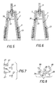
- FIGs 9, 10 and 11 there are schematically illustrated the steps of a pricking carried out with a needle 9 equipped with the protection device shown by Figures 5 and 6.
- Fig. 9 clearly shows the needle 9 and the associated protection device 1 locked together with the spring 13 compressed.
- the lever device 31 or 33 becomes disengaged thanks to the flow of the liquid inside the syringe, so that the device 31 or 33 snaps and releases the spring 13 which in turn causes the cap 1 to shift forward until it abuts against the patient's skin.
- the needle 9 is extracted from the skin and the spring 13 urges the cap 1 to completely shelter the piercing tip of the needle 9.
Abstract
Description
Claims (7)
- A hypodermic needle with an after-use protection device against infection risks,
comprisinga base (7) supporting the needle (9);a cap (1) slideably mounted along said needle having piercing-resistant walls (3) with an inner irregular profile (5), said cap (1) being provided at its closed end (15) with a hole (17) for the passage of the needle (9) and being snap secured to said base (7);cap propelling means (13) with a marked propulsive capability between said cap (1) and said base (7), said propelling means (13) being secured to said base (7), surrounding said needle (9) and retaining said cap (1) to shelter the needle (9) when released;
characterized in that inside the cap (1) there is provided a pocket (21), outwardly defined by the cap walls (3) and inwardly by a pierceable metal foil (23), said pocket containing an adhesive and air-hardening material (25),
whereby the needle is rendered no longer separable from the cap when said propelling means (13) is released and said needle (9) is sticked into said adhesive and air-hardening material (25) . - A hypodermic needle as claimed in claim 1, characterized in that said cap propelling means are provided by a coil spring or sheath.
- A hypodermic needle as claimed in claim 1, characterized in that said hole (17) is eccentric with respect to the tip (15) of the cap (1).
- A hypodermic needle as claimed in claim 1, characterized in that said adhesive and air-hardening material (25) are supported inside said pocket (21) by a resilient spongy material.
- A hypodermic needle as claimed in claims 1 to 4, characterized in that the cap (1) is locked to the base (7) of the needle, by a series of cooperating snap retainers (27) located on the inner wall of the cap (1) and on the outer wall of the needle base (7) mating the cap (1) whereby a short manually imparted displacement of the cap (1) causes the cap to be released from the base (7), and allows it to spring upward to wholly shelter the needle (9), with said displacement that can be imparted even with the needle (9) still inserted in the skin, so that the cap (1) is released and springs forward to shelter the exposed portion of the needle (9), and remains ready to wholly cover it, as soon as it will be extracted from the skin.
- A hypodermic needle as claimed in claims 1 to 4, characterized in that the cap (1) is retained by the base (7) of the needle (9) through a series of snap retainers (29) provided with an inclined surface whereby the pressure applied by the skin to the needle cap (1) while pricking lowers said cap (1) with respect to its mating base (7), causing said locks (29) to slide along said inclined surfaces, so that the cap (1) is rotated with respect to the base (7) and it is disengaged from said base (7), with the sheltering of the needle by the cap (1) being ensured after the prick has been executed.
- A hypodermic needle as claimed in claims 1 to 4, characterized in that the cap (1) is linked to the base (7) of the needle (9) by a lever device (31 or 33), pivotally secured to the wall of the base (7) and cooperating with a recess (35) in the wall (3) of the cap (1) whereby as soon as the needle (9) is inserted into the skin, the fluid displaced by the syringe piston acts upon said lever element (31, 33) and causes it to rotate enough to disengage it from the recess (35) provided in the cap (1), thus allowing the action of the cap propulsion means (13).
Applications Claiming Priority (3)
| Application Number | Priority Date | Filing Date | Title |
|---|---|---|---|
| ITTO920597 | 1992-07-13 | ||
| ITTO920597A IT1257913B (en) | 1992-07-13 | 1992-07-13 | HYPODERMIC NEEDLE WITH PROTECTION DEVICE. |
| PCT/EP1993/001619 WO1994001152A1 (en) | 1992-07-13 | 1993-06-22 | A hypodermic needle with protection device |
Publications (2)
| Publication Number | Publication Date |
|---|---|
| EP0603365A1 EP0603365A1 (en) | 1994-06-29 |
| EP0603365B1 true EP0603365B1 (en) | 1998-09-02 |
Family
ID=11410604
Family Applications (1)
| Application Number | Title | Priority Date | Filing Date |
|---|---|---|---|
| EP93914719A Expired - Lifetime EP0603365B1 (en) | 1992-07-13 | 1993-06-22 | A hypodermic needle with protection device |
Country Status (9)
| Country | Link |
|---|---|
| US (1) | US5554131A (en) |
| EP (1) | EP0603365B1 (en) |
| AT (1) | ATE170407T1 (en) |
| CA (1) | CA2118909A1 (en) |
| DE (1) | DE69320773T2 (en) |
| DK (1) | DK0603365T3 (en) |
| ES (1) | ES2122029T3 (en) |
| IT (1) | IT1257913B (en) |
| WO (1) | WO1994001152A1 (en) |
Cited By (6)
| Publication number | Priority date | Publication date | Assignee | Title |
|---|---|---|---|---|
| US6254575B1 (en) | 1999-11-04 | 2001-07-03 | Specialized Health Products | Reaccessible medical needle safety devices and methods |
| US6280420B1 (en) | 1999-11-04 | 2001-08-28 | Specialized Health Products | Reaccessible medical needle safety devices and methods |
| US6592556B1 (en) | 2000-07-19 | 2003-07-15 | Tyco Healthcare Group Lp | Medical needle safety apparatus and methods |
| US7862547B2 (en) | 1999-11-04 | 2011-01-04 | Tyco Healthcare Group Lp | Safety shield for medical needles |
| US8172809B2 (en) | 1999-11-04 | 2012-05-08 | Tyco Healthcare Group Lp | Safety shield apparatus and mounting structure for use with medical needle devices |
| US8496627B2 (en) | 2006-03-21 | 2013-07-30 | Covidien Lp | Passive latch ring safety shield for injection devices |
Families Citing this family (38)
| Publication number | Priority date | Publication date | Assignee | Title |
|---|---|---|---|---|
| IT1257913B (en) * | 1992-07-13 | 1996-02-16 | HYPODERMIC NEEDLE WITH PROTECTION DEVICE. | |
| GB2283429B (en) * | 1993-11-04 | 1998-04-01 | David Howell Jenkins | A needle point protector |
| FR2733156A1 (en) * | 1995-04-20 | 1996-10-25 | Lafarge Paul | Disposable injection or sampling needle |
| SE9502285D0 (en) * | 1995-06-22 | 1995-06-22 | Pharmacia Ab | Improvements related to injections |
| US7111767B2 (en) * | 1997-04-24 | 2006-09-26 | Simpson Strong-Tie Company, Inc. | Power actuated fastener system |
| US5897082A (en) * | 1997-07-08 | 1999-04-27 | Losada; Al | Power actuated fastener for pipe |
| FR2767469B1 (en) * | 1997-08-25 | 2000-06-16 | Raphael Mosseri | PROTECTION DEVICE FOR A CUTTING AND / OR PERFORATING TOOL |
| US6080135A (en) * | 1998-08-26 | 2000-06-27 | Van Stokkum; Petrus J. M. | Automatically activated protection system for hypodermic needles |
| US6261264B1 (en) * | 1999-07-23 | 2001-07-17 | Frank A. Tamaro | Safety cap assembly for needles |
| US6217559B1 (en) | 2000-06-13 | 2001-04-17 | Livingston Foster | Automatic safety syringe construction |
| US6623458B2 (en) * | 2001-09-26 | 2003-09-23 | B. Braun Melsungen, Ag | Spring launched needle safety clip |
| US7354422B2 (en) * | 2001-09-26 | 2008-04-08 | B. Braun Melsungen Ag | Spring launched needle safety clip |
| US20030133768A1 (en) * | 2002-01-11 | 2003-07-17 | Alfonso Losada | Fastener assembly having grooves for use with a power actuated gun |
| CA2480072A1 (en) | 2002-03-26 | 2003-10-09 | Becton, Dickinson And Company | Multi-stage fluid delivery device and method |
| CA2493728C (en) * | 2002-07-22 | 2013-10-29 | Becton, Dickinson And Company | Patch-like infusion device |
| US7249701B2 (en) | 2002-11-05 | 2007-07-31 | Simpson Strong-Tie Co., Inc. | Power actuated gun with fastener feeding track and automatic firing |
| US6884224B2 (en) * | 2003-04-04 | 2005-04-26 | Norfolk Medical | Needle protection device |
| WO2005018705A2 (en) * | 2003-08-12 | 2005-03-03 | Becton, Dickinson And Company | Patch-like infusion device |
| ES2906559T3 (en) | 2004-09-10 | 2022-04-19 | Becton Dickinson Co | Patch type infusion device |
| US9283314B2 (en) * | 2005-09-21 | 2016-03-15 | Abiomed, Inc. | Cannula systems |
| JP4994775B2 (en) | 2006-10-12 | 2012-08-08 | 日本コヴィディエン株式会社 | Needle point protector |
| US8057431B2 (en) | 2006-12-21 | 2011-11-15 | B. Braun Melsungen Ag | Hinged cap for needle device |
| US9924898B2 (en) * | 2008-04-15 | 2018-03-27 | Becton, Dickinson And Company | Flash activated passive shielding needle assembly |
| JP5894082B2 (en) | 2009-12-16 | 2016-03-23 | ベクトン・ディキンソン・アンド・カンパニーBecton, Dickinson And Company | Self-injection device |
| JP5650242B2 (en) | 2009-12-16 | 2015-01-07 | ベクトン・ディキンソン・アンド・カンパニーBecton, Dickinson And Company | Self injection device |
| EP2512551B1 (en) | 2009-12-16 | 2019-03-20 | Becton, Dickinson and Company | Self-injection device |
| ES2565405T3 (en) | 2009-12-16 | 2016-04-04 | Becton Dickinson And Company | Auto injection device |
| DK2512559T3 (en) | 2009-12-16 | 2019-03-25 | Becton Dickinson Co | SELF-INJECTIVE DEVICE |
| ES2617145T3 (en) | 2009-12-16 | 2017-06-15 | Becton, Dickinson And Company | Automatic injection device |
| US8858509B2 (en) | 2010-05-05 | 2014-10-14 | Safety Syringes, Inc. | Needle based helical coil safety device |
| CN103153360B (en) | 2010-09-02 | 2016-04-06 | 贝克顿·迪金森公司 | Have band activate interceptor pin lid from injection device |
| US8486024B2 (en) | 2011-04-27 | 2013-07-16 | Covidien Lp | Safety IV catheter assemblies |
| US8591467B2 (en) | 2011-07-25 | 2013-11-26 | Covidien Lp | Vascular access assembly and safety device |
| WO2013048975A1 (en) | 2011-09-26 | 2013-04-04 | Covidien Lp | Safety catheter |
| EP2760521B1 (en) | 2011-09-26 | 2016-01-06 | Covidien LP | Safety iv catheter and needle assembly |
| US8834422B2 (en) | 2011-10-14 | 2014-09-16 | Covidien Lp | Vascular access assembly and safety device |
| US8926489B2 (en) * | 2012-07-17 | 2015-01-06 | Robert W. Brunson | Hypodermic needle containment system |
| JP6010220B2 (en) | 2013-08-14 | 2016-10-19 | テルモ株式会社 | Syringe |
Family Cites Families (9)
| Publication number | Priority date | Publication date | Assignee | Title |
|---|---|---|---|---|
| US4728321A (en) * | 1987-04-16 | 1988-03-01 | Ming-Chiu Wu | Syringe cap with adhesive holding plug |
| US4725267A (en) * | 1987-05-06 | 1988-02-16 | Vaillancourt Vincent L | Post-injection needle sheath |
| JPH03504205A (en) * | 1988-05-06 | 1991-09-19 | ディークス,デビッド,ジョン | Needle |
| CA1315166C (en) * | 1988-10-05 | 1993-03-30 | John S. Parry | Injection devices |
| ES2015427A6 (en) * | 1989-07-21 | 1990-08-16 | Sempere Escudero Philippe | A safety protective device for injection needles. |
| GB8919131D0 (en) * | 1989-08-23 | 1989-10-04 | Riker Laboratories Inc | Inhaler |
| US5232454A (en) * | 1990-08-01 | 1993-08-03 | Smiths Industries Medical Systems, Inc. | Safety needle container |
| US5232455A (en) * | 1991-01-07 | 1993-08-03 | Smiths Industries Medical Systems, Inc. | Syringe with protective housing |
| IT1257913B (en) * | 1992-07-13 | 1996-02-16 | HYPODERMIC NEEDLE WITH PROTECTION DEVICE. |
-
1992
- 1992-07-13 IT ITTO920597A patent/IT1257913B/en active IP Right Grant
-
1993
- 1993-06-22 DK DK93914719T patent/DK0603365T3/en active
- 1993-06-22 ES ES93914719T patent/ES2122029T3/en not_active Expired - Lifetime
- 1993-06-22 CA CA002118909A patent/CA2118909A1/en not_active Abandoned
- 1993-06-22 AT AT93914719T patent/ATE170407T1/en not_active IP Right Cessation
- 1993-06-22 EP EP93914719A patent/EP0603365B1/en not_active Expired - Lifetime
- 1993-06-22 US US08/199,162 patent/US5554131A/en not_active Expired - Fee Related
- 1993-06-22 DE DE69320773T patent/DE69320773T2/en not_active Expired - Fee Related
- 1993-06-22 WO PCT/EP1993/001619 patent/WO1994001152A1/en active IP Right Grant
Cited By (8)
| Publication number | Priority date | Publication date | Assignee | Title |
|---|---|---|---|---|
| US6254575B1 (en) | 1999-11-04 | 2001-07-03 | Specialized Health Products | Reaccessible medical needle safety devices and methods |
| US6280420B1 (en) | 1999-11-04 | 2001-08-28 | Specialized Health Products | Reaccessible medical needle safety devices and methods |
| US6796968B2 (en) | 1999-11-04 | 2004-09-28 | Tyco Healthcare Group Lp | Reaccessible medical needle safety devices and methods |
| US7862547B2 (en) | 1999-11-04 | 2011-01-04 | Tyco Healthcare Group Lp | Safety shield for medical needles |
| US8172809B2 (en) | 1999-11-04 | 2012-05-08 | Tyco Healthcare Group Lp | Safety shield apparatus and mounting structure for use with medical needle devices |
| US8226617B2 (en) | 1999-11-04 | 2012-07-24 | Tyco Healthcare Group Lp | Safety shield apparatus and mounting structure for use with medical needle devices |
| US6592556B1 (en) | 2000-07-19 | 2003-07-15 | Tyco Healthcare Group Lp | Medical needle safety apparatus and methods |
| US8496627B2 (en) | 2006-03-21 | 2013-07-30 | Covidien Lp | Passive latch ring safety shield for injection devices |
Also Published As
| Publication number | Publication date |
|---|---|
| IT1257913B (en) | 1996-02-16 |
| DE69320773D1 (en) | 1998-10-08 |
| CA2118909A1 (en) | 1994-01-20 |
| WO1994001152A1 (en) | 1994-01-20 |
| DE69320773T2 (en) | 1999-04-29 |
| ES2122029T3 (en) | 1998-12-16 |
| ITTO920597A0 (en) | 1992-07-13 |
| EP0603365A1 (en) | 1994-06-29 |
| US5554131A (en) | 1996-09-10 |
| DK0603365T3 (en) | 1999-05-31 |
| ITTO920597A1 (en) | 1994-01-13 |
| ATE170407T1 (en) | 1998-09-15 |
Similar Documents
| Publication | Publication Date | Title |
|---|---|---|
| EP0603365B1 (en) | A hypodermic needle with protection device | |
| US10960143B2 (en) | Auto-injector with active agent container latching | |
| US5295965A (en) | Automatic injectors | |
| US5226882A (en) | Single-use syringe with non-retractable piston | |
| JP4339260B2 (en) | Injection device with needle protection device | |
| CA1337167C (en) | Needle housing with retractable needle | |
| US5562626A (en) | Safety syringe | |
| US5183468A (en) | Snap ring needle guard | |
| EP1762259B1 (en) | Inserter for an infusion set with a first and second spring units | |
| CA2216448C (en) | Safety stylet for intravenous catheter insertion | |
| JP2840867B2 (en) | Safety syringe | |
| JP3217780B2 (en) | Safety syringe with retractable needle | |
| CA2127359C (en) | Automatic injectors | |
| CN204219535U (en) | Pen needle assemblies | |
| EP0747085A2 (en) | I.V. catheter assembly with automatic cannula tip guard | |
| US20040039336A1 (en) | Auto-injector | |
| NZ224396A (en) | Cannula insertion set comprising a retractable needle and a hollow handle | |
| JPH06500706A (en) | syringe for hypodermic injection | |
| EP1252907A1 (en) | Protective device for a fillable injection syringe | |
| EP1075850B1 (en) | Apparatus for intravenous catheter insertion | |
| JP2007509658A (en) | Automatic injection device | |
| CA2264532A1 (en) | Pre-filled retractable needle injection devices | |
| US5709667A (en) | Hypodermic needle protection system | |
| AU2003101038A4 (en) | Safety Fluid Injecting/Sampling Apparatus | |
| JPH09299483A (en) | Injection needle with sliding cover |
Legal Events
| Date | Code | Title | Description |
|---|---|---|---|
| PUAI | Public reference made under article 153(3) epc to a published international application that has entered the european phase |
Free format text: ORIGINAL CODE: 0009012 |
|
| 17P | Request for examination filed |
Effective date: 19940223 |
|
| AK | Designated contracting states |
Kind code of ref document: A1 Designated state(s): AT BE CH DE DK ES FR GB LI NL |
|
| 17Q | First examination report despatched |
Effective date: 19960619 |
|
| GRAG | Despatch of communication of intention to grant |
Free format text: ORIGINAL CODE: EPIDOS AGRA |
|
| GRAG | Despatch of communication of intention to grant |
Free format text: ORIGINAL CODE: EPIDOS AGRA |
|
| GRAH | Despatch of communication of intention to grant a patent |
Free format text: ORIGINAL CODE: EPIDOS IGRA |
|
| GRAH | Despatch of communication of intention to grant a patent |
Free format text: ORIGINAL CODE: EPIDOS IGRA |
|
| GRAA | (expected) grant |
Free format text: ORIGINAL CODE: 0009210 |
|
| AK | Designated contracting states |
Kind code of ref document: B1 Designated state(s): AT BE CH DE DK ES FR GB LI NL |
|
| REF | Corresponds to: |
Ref document number: 170407 Country of ref document: AT Date of ref document: 19980915 Kind code of ref document: T |
|
| REG | Reference to a national code |
Ref country code: CH Ref legal event code: EP |
|
| REF | Corresponds to: |
Ref document number: 69320773 Country of ref document: DE Date of ref document: 19981008 |
|
| REG | Reference to a national code |
Ref country code: CH Ref legal event code: NV Representative=s name: KEMIA S.A. |
|
| REG | Reference to a national code |
Ref country code: ES Ref legal event code: FG2A Ref document number: 2122029 Country of ref document: ES Kind code of ref document: T3 |
|
| ET | Fr: translation filed | ||
| REG | Reference to a national code |
Ref country code: DK Ref legal event code: T3 |
|
| PGFP | Annual fee paid to national office [announced via postgrant information from national office to epo] |
Ref country code: FR Payment date: 19990610 Year of fee payment: 7 |
|
| PGFP | Annual fee paid to national office [announced via postgrant information from national office to epo] |
Ref country code: ES Payment date: 19990618 Year of fee payment: 7 |
|
| PGFP | Annual fee paid to national office [announced via postgrant information from national office to epo] |
Ref country code: DK Payment date: 19990621 Year of fee payment: 7 |
|
| PGFP | Annual fee paid to national office [announced via postgrant information from national office to epo] |
Ref country code: GB Payment date: 19990622 Year of fee payment: 7 |
|
| PGFP | Annual fee paid to national office [announced via postgrant information from national office to epo] |
Ref country code: CH Payment date: 19990623 Year of fee payment: 7 |
|
| PGFP | Annual fee paid to national office [announced via postgrant information from national office to epo] |
Ref country code: NL Payment date: 19990630 Year of fee payment: 7 Ref country code: AT Payment date: 19990630 Year of fee payment: 7 |
|
| PLBE | No opposition filed within time limit |
Free format text: ORIGINAL CODE: 0009261 |
|
| STAA | Information on the status of an ep patent application or granted ep patent |
Free format text: STATUS: NO OPPOSITION FILED WITHIN TIME LIMIT |
|
| PGFP | Annual fee paid to national office [announced via postgrant information from national office to epo] |
Ref country code: BE Payment date: 19990728 Year of fee payment: 7 |
|
| PGFP | Annual fee paid to national office [announced via postgrant information from national office to epo] |
Ref country code: DE Payment date: 19990729 Year of fee payment: 7 |
|
| 26N | No opposition filed | ||
| PG25 | Lapsed in a contracting state [announced via postgrant information from national office to epo] |
Ref country code: GB Free format text: LAPSE BECAUSE OF NON-PAYMENT OF DUE FEES Effective date: 20000622 Ref country code: DK Free format text: LAPSE BECAUSE OF NON-PAYMENT OF DUE FEES Effective date: 20000622 Ref country code: AT Free format text: LAPSE BECAUSE OF NON-PAYMENT OF DUE FEES Effective date: 20000622 |
|
| PG25 | Lapsed in a contracting state [announced via postgrant information from national office to epo] |
Ref country code: ES Free format text: THE PATENT HAS BEEN ANNULLED BY A DECISION OF A NATIONAL AUTHORITY Effective date: 20000623 |
|
| PG25 | Lapsed in a contracting state [announced via postgrant information from national office to epo] |
Ref country code: LI Free format text: LAPSE BECAUSE OF NON-PAYMENT OF DUE FEES Effective date: 20000630 Ref country code: CH Free format text: LAPSE BECAUSE OF NON-PAYMENT OF DUE FEES Effective date: 20000630 Ref country code: BE Free format text: LAPSE BECAUSE OF NON-PAYMENT OF DUE FEES Effective date: 20000630 |
|
| BERE | Be: lapsed |
Owner name: LACIVITA ANTONIO Effective date: 20000630 Owner name: CARPINELLI PIA Effective date: 20000630 |
|
| PG25 | Lapsed in a contracting state [announced via postgrant information from national office to epo] |
Ref country code: NL Free format text: LAPSE BECAUSE OF NON-PAYMENT OF DUE FEES Effective date: 20010101 |
|
| GBPC | Gb: european patent ceased through non-payment of renewal fee |
Effective date: 20000622 |
|
| REG | Reference to a national code |
Ref country code: CH Ref legal event code: PL |
|
| REG | Reference to a national code |
Ref country code: DK Ref legal event code: EBP |
|
| PG25 | Lapsed in a contracting state [announced via postgrant information from national office to epo] |
Ref country code: FR Free format text: LAPSE BECAUSE OF NON-PAYMENT OF DUE FEES Effective date: 20010228 |
|
| NLV4 | Nl: lapsed or anulled due to non-payment of the annual fee |
Effective date: 20010101 |
|
| REG | Reference to a national code |
Ref country code: FR Ref legal event code: ST |
|
| PG25 | Lapsed in a contracting state [announced via postgrant information from national office to epo] |
Ref country code: DE Free format text: LAPSE BECAUSE OF NON-PAYMENT OF DUE FEES Effective date: 20010403 |
|
| REG | Reference to a national code |
Ref country code: ES Ref legal event code: FD2A Effective date: 20020204 |